A9K 0.8 C300 Installation Guide
2015-07-30
: Logic C300 Installation Guide C300_Installation_Guide s c300hd content
Open the PDF directly: View PDF ![]() .
.
Page Count: 76

Installation Guide

C300HD Installation Guide
Master Studio System
Installation Guide
Version 2.0.1
82S6PC3010B
Solid State Logic
SVISINOO UND

C300HD Installation Guide
Begbroke, Oxford, England, OX5 1RU • +44 (0)1865 842300
320 West 46th Street, 2nd Floor, New York, NY 10036, USA • +1 (1) 212 315 1111
Suite 401, 5757 Wilshire Blvd, Los Angeles, CA 90036, USA • +1 (1) 323 549 9090
3-55-14 Sendagaya, Shibuya-Ku,Tokyo 151-0051, Japan • +81 (0)3 5474 1144
7 bis, rue de la Victoire, le Blanc Mesnil, Paris 93150, France • +33 (0)1 48 67 84 85
Via Timavo 34, 20124 Milano, Italy • +39 (0)39 2328 094
Visit SSL at URL: http://www.solid-state-logic.com
© Solid State Logic
All Rights reserved under International and Pan-American Copyright Conventions
C100HD, C100HD-S, C200, C300HD, Centuri, C-SB StageBox, NetBridge,
Solid State Logic and SSL are trademarks of Solid State Logic
All other product names and trademarks are the property of their respective owners
No part of this publication may be reproduced in any form or
by any means, whether mechanical or electronic, without the
written permission of Solid State Logic, Oxford, England
Solid State Logic
SVISINOO UND
As research and development is a continual process, Solid State Logic reserves the right
to change the features and specifications described herein without notice or obligation
E&OE

Contents
Section 1 Introduction ----2
Section 2 Safety Considerations ---3
Safety Warnings ----4
CE/FCC/WEEE Certification and Directives 5
Section 3 Pre-Installation Information -6
Services Provided by SSL ---6
Physical/Structural ----7
Console Footprint and Side Profile -8
Centuri and Stagebox Side View --10
Technical ----11
Section 4 System Components --13
Console Frame ----13
The Centuri Processor ---15
The Centuri Processor Cards --16
C-SB Stagebox (option) ---21
NetBridge (option) ----23
KVM Switching ----25
Script Tray (option) ----25
Loudspeaker Shelf (option) ---25
TFT external input (option) ---25
Section 5 Installation ----27
Power Connections ----27
Console Control ----29
Sync ----29
I/O – MicAmp Card ---31
I/O – Analogue Card ---31
I/O – Digital Card ----33
I/O – MADI Card ----33
GPI/O Card ----35
C-SB Stagebox Wiring ---37
Netbridge ----39
Talkback and Oscillator ---41
Phasescope and Meter Wiring --43
DAW Midi interface ----45
Appendices A Equipment Specifications ---47
B Connector Details ----51
C Connector Pinouts: Console --53
Processor Crate - 55
NetBridge --61
D Audio Interfacing ----63
E Environmental Specification --65
F Stagebox Installation Requirements - 67
G Machine Control ----68
H SSL Part Numbers by Description - 71
Page 1

Section 1 – Introduction
The object of this manual is to provide purchasers of the C300HD™ Console and Centuri™ Processor with information
in the following areas:
• Safety considerations
• Installation requirements
• Items supplied: – Main components and optional items
• Installation: – Physical assembly
– Electrical connections and cabling
– System options
• Specifications and Physical dimensions
• Pinouts of standard connectors
The information provided by this manual is relevant to all of the versions of the C300HD.
The aspects of the C300HD which can be customised – frame size, channel layout, meter panel as examples – will be fully
documented in the Custom Specification information for a specific console.
The Custom Specification information, which details the actual console as built, will be found in Section 10 of the console’s
Service Manual.
Page 2
C300HD Installation Guide

Section2 – Safety Considerations
This section contains definitions and warnings, and practical information to ensure a safe working environment. Please take
time to read this section before undertaking any installation work.
Definitions
‘Maintenance’
All maintenance must be carried out by fully trained personnel.
Note: it is advisable to observe suitable ESD precautions when maintaining electronic assemblies.
‘Non-User Adjustments’
Adjustments or alterations to the equipment may affect the performance such that safety and/or international
compliance standards may no longer be met.Any such adjustments must therefore only be carried out by fully trained
personnel.
‘Users’
This equipment is designed for use solely by engineers and competent operators skilled in the use of professional
audio equipment.
‘Environment’
This product is a class A product intended to form an integrated component part of a professional audio recording,
mixing, TV, radio broadcast or similar studio wherein it will perform to specification providing that it is installed
according to professional practice.
Installation Instructions
Voltage Selection and Fusing
Although the majority of SSL equipment uses auto-ranging power supplies, some sub-systems have user-selectable voltage
inlets. Always confirm that the input mains voltage range is set correctly before applying power. Always isolate the mains
supply before changing the input range setting.
If it is ever necessary to replace a blown mains-fuse, then always use the correct rating and type of replacement. If a
correctly rated fuse continues to blow, then a fault exists and the cause should be investigated or the unit returned to SSL
for repair/replacement as appropriate.
Details of mains settings and correct fuse ratings can be found in Appendix A of this manual.
Electrical Safety Warning
When installing or servicing any item of SSL equipment with power applied, when cover panels are
removed, HAZARDOUS CONDITIONS CAN EXIST.
These hazards include: High voltages
High energy stored in capacitors
High currents available from DC power busses
Hot component surfaces.
Any metal jewellery (watches, bracelets, neck-chains and rings) that could inadvertently come into contact
with uninsulated parts should always be removed before reaching inside powered equipment.
Safety Considerations
Section 2
Page 3

Safety Earth Connection
Any mains powered item of SSL equipment that is supplied with a 3-core mains lead (whether connectorised or not) should
always have the earth wire connected to the mains supply ground.This is the safety earth and grounds the exposed metal
parts of the racks and cases and should not be removed for any reason.
Mains Supply and Phases
To ensure safe operation of this equipment, connect only to an ac. power source that contains a protective earthing (PE)
conductor.This equipment is designed for connection to single phase supplies with the neutral conductor at earth potential
– category TN or TT – and is fitted with a protective fuse in the live conductor only. This equipment is not designed for
use with live and neutral connections reversed or where the neutral conductor is not at earth potential (IT supplies).This
equipment should not be connected to a power system that switches open the return (neutral) lead when the return lead
also functions as the protective earth (PE).
All mains powered assemblies must be connected to the same mains phase.
Mains cables will be coded with either of the following colour schemes:
1or 2
LIVE: Brown Black
NEUTRAL: Blue White
EARTH: Yellow/Green Green
Mains Isolation and Over-Current Protection
An external disconnect device (switch) is required for this equipment which must be installed according to current wiring
regulations. A detachable power cord, if fitted to this equipment, is a suitable disconnect device; otherwise an approved
disconnect switch is required – the rating of which is defined in the product specification (Appendix A) and on the
equipment itself.
An external over-current protection device is required to protect the wiring to this equipment which must be installed
according to the current wiring regulations.The fusing or breaking-current is defined in the product specification. In certain
countries this function is supplied by use of a fused plug.
Some equipment (specifically units with PSU Redundancy) utilises multiple power sources. This is clearly marked on the
equipment.The finished installation must also be clearly marked to ensure that all sources of power are removed before
servicing begins.
Physical Safety
Most subsystems are too heavy for one person to lift.Take particular care when removing the computer chassis from the
equipment rack.
If the console trim is removed for any reason then there may be sharp edges exposed on the frame metalwork.
Page 4
C300HD Installation Guide
CE Certification
The C300HD/Centuri system is CE compliant. Note that the majority of cables supplied with SSL equipment are
fitted with ferrite rings at each end.This is to comply with the current regulations and these ferrites should not
be removed.
If any of the console metalwork is modified in any way – particularly the addition of holes for custom switches etc. – this
may the adversely affect the CE certification status of the product.
FCC Certification
The equipment which forms a C300HD/Centuri system has been tested and found to comply with the limits for
a Class A digital device, pursuant to part 15 of the FCC Rules.These limits are designed to provide reasonable
protection against harmful interference when the equipment is operated in a commercial environment.
This equipment generates, uses and can radiate radio frequency energy and, if not installed and used in accordance with
the instruction manual, may cause harmful interference to radio communications. Operation of this equipment in a
residential area is likely to cause harmful interference in which case the user will be required to correct the interference
at his own expense.
Instructions for Disposal of WEEE by Users in the European Union
The symbol shown here, which is on the product or on its packaging, indicates that this product must not
be disposed of with other waste. Instead, it is the user’s responsibility to dispose of their waste equipment
by handing it over to a designated collection point for recycling of waste electrical and electronic
equipment.The separate collection and recycling of your waste equipment at the time of disposal will help
to conserve natural resources and ensure that it is recycled in a manner that protects human health and
the environment. For more information about where you can drop off your waste equipment for recycling,
please contact your local city office, your household waste disposal service or where you purchased the
product.
Safety Considerations
Section 2
Page 5

Section 3 – Pre Installation Information
Physical installation of the console is normally carried out by a specialised transportation company. In some cases this will
have been arranged by the local SSL office, in other cases by the facility.
The cables that run between console and processor can be shipped in advance of the console in a separate kit (the pre-
install kit). These cables should be installed by the facility engineers. Instructions for installing these cables are found on
pages 26 to 31 of this manual.
Refer to Appendix A for weights and power consumption information.
Before the console is installed all building work should be completed and the environment MUST be clean otherwise the
warranty will be rendered invalid.
Before commissioning can take place the following must be completed:
• Air Conditioning installed, tested, blown-through and working
• Lighting installed and tested
• Cable Trunking installed
• Wall and floor finishes completed
• Power Distribution installed and tested
• Cables installed and tested
• Monitor loudspeakers installed and working
• Other utilities (telephone, water etc.) available
Services provided by SSL
Commissioning
All C300HD systems include on-site commissioning by an SSL engineer.This is usually expected to take from 2 to 4 days
depending on system size, configuration and options. Large systems, or consoles split for shipment, may require an
additional 1–2 days of commissioning time.
You will be contacted by your local SSL office or agent shortly before delivery to arrange a commissioning date.
Training
Three days of standard operator training are provided with each C300HD system. If required, this is scheduled to take
place immediately following the commissioning period and is usually carried out by the commissioning engineer. A further
day of advanced operator training is available at additional cost.
On-site maintenance training is also available at additional cost.This can be either one day for a basic overview or two days
for more advanced training.
Training should be requested at time of order. For all training, we recommend that no more than five persons attend each
session. If the use of an interpreter is necessary the training period may need to be extended (at additional cost). Note
that travel and subsistence costs are not normally included. Please contact SSL’s training department at: support@solid-
state-logic.com.
Warranty
All systems normally include 13 months warranty from date of shipment.This does not include consumable items such as
magnetic media, disks etc. Further details may be found in SSL’s Conditions of Trading (printed on the reverse of all SSL
invoices).
Page 6
C300HD Installation Guide

Physical Requirements
Console Control Surface
The console control surface can be specified to have from 16 to 96 physical channels so the size and weight will vary
considerably. A dimensioned footprint drawing for each specific console control surface can be provided by SSL’s Project
Engineering Department. See page 46 for an example of a 32-channel footprint.
Consoles can be built with split points at any profile.The console can then be split for shipment to simplify installation into
client’s premises. Reassembly will be by SSL engineers.
Cable sets are available in 10, 16, 25, 48 and 80m standard lengths.
Cables for the connection of ancillary functions: meters, talkback or any custom switching etc. are not supplied by SSL
and will need to be provided by the facility. See pages 47–49 for wiring information.
Refer to Appendix A for weight and power consumption information.
Rack Mounting Equipment – Centuri, NetBridge and Stageboxes
The Centuri Processor is a 15U height chassis into which a range of I/O cards can be fitted.The system’s processing and
DSP resource is also housed in the Centuri rack.The Centuri is therefore fitted with cooling fans and is expected to be
housed in a separate ‘machine’ room.
A 19” equipment rack will need to be provided into which the Centuri Processor can be mounted. Note when positioning
the rack that cards are inserted into the Centuri Processor from both the front and the rear depending on function.
Clearance for access to cards must therefore be provided both in front of and behind the rack (see page 10 for service
clearance diagram).
A MIDI interface is supplied as standard on the C300HD. Access to the MIDI connectors is via a separate 1U breakout
panel which connects to the rear of the Centuri rack.A standard 800mm deep equipment rack will have sufficient room
for the panel to be located directly behind the Centuri. If shorter racks are used then an additional 1U of rack space must
be allocated for the panel. See page 45 for additional information.
NetBridge – which is an option – is a 2U high rack mounting unit.
Remotely located stageboxes (C-SBs) – which are also optional – may be specified.These are 14U rack units.
Centuri, NetBridge and stagebox units MUST be supported on shelves and not only by the rack ears.
Acoustic Isolation
Because of the noise generated by cooling fans the Centuri core should be located in a separate machine room.Adequate
noise isolation should exist between the machine room and control room/recording areas.
Noise figures for individual units are given in Appendix A.
Pre Installation Information
Section 3
Page 7
C300HD Installation Guide
Page 8
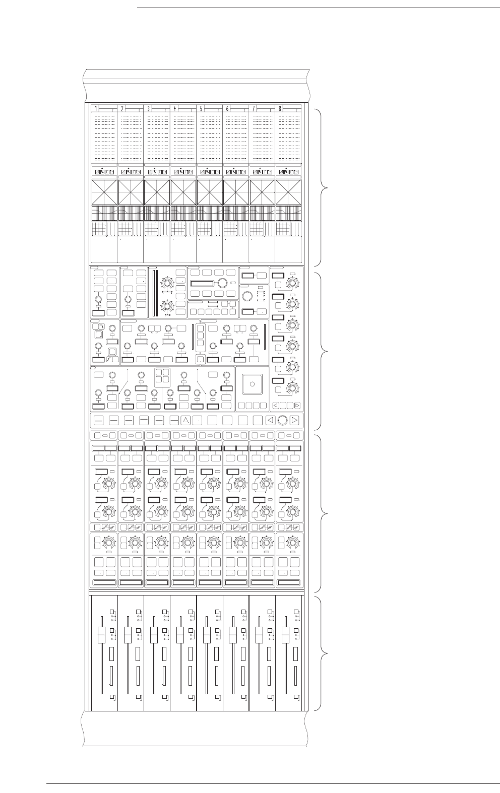
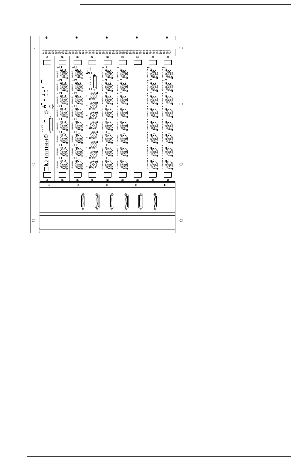
1 – 8 9 – 16 Centre Section17 – 24 25 – 32
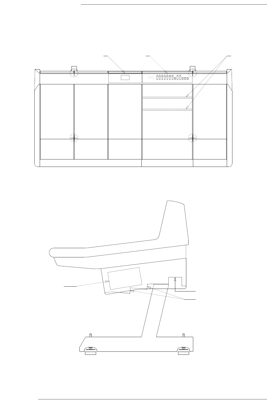
Connector Panels and Power Supplies
Mains and audio connectors
Console connectors
Power supplies
Mains panel Audio interface
panel
Console interface
panels

Air Conditioning Requirements
Air conditioning will almost certainly be required for both the Machine and Control rooms in order to maintain the
temperature and humidity to within the required levels.
Power dissipation figures for console control surface and equipment rack are listed in Appendix A.
Appendix E contains the environmental specification for SSL equipment.
Cable Ducting
Cable ducting will be required between the console and the Machine room (as well as to any outboard racks and the
recording areas).The ducting provided should be of sufficient size such that approximately 50mm x 35mm is available for
console surface connection. It is not possible to route cables down through the console legs.
The connectors for all control and interface cables are located beneath the console’s Centre Section.The connector panels
are orientated so that cables will route towards the rear of the desk.
The connectors for ancillary functions, such as talkback and metering etc., are located on a panel at the rear of the Centre
Section.
The mains input power connector will be located on a separate panel.This panel is usually positioned in a bay adjacent to
the Centre Section nearest to the centre of the console but may vary due to console layout.
Service Access
Access to all major electronic assemblies within the frame is either from the front or from beneath the console.The meter
LCD panels are retained by finger-screw fastener beneath the top trim.The top trim is designed to hinge upwards to allow
access to these screws. If the console is being built into restricted space – as in some mobile installations – then always
allow a minimum of 80mm clearance above the top trim.
Sufficient clearance must be provided in front of and behind the rack into which the Centuri processor is installed so that
cards can easily be removed. See the drawing on page 10 for minimum clearances.
Pre Installation Information
Section 3
Page 9
C300HD Installation Guide
Page 10
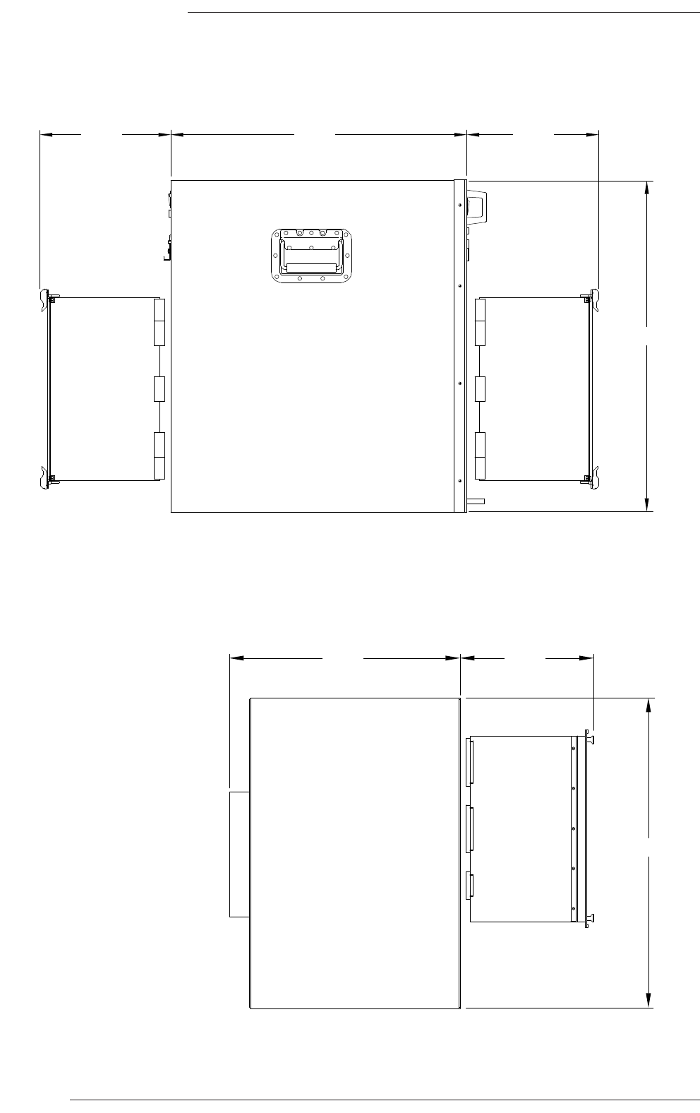
Centuri Processor Crate (side view) Showing Card Access
C-SB Crate (side view) Showing Card Access
Dimensions in mm
592 270
15U
14U
270
462 270
Front
Rear
Front
Rear

Technical Requirements
System Synchronisation
The Centuri Processor requires an external Video Reference Signal to derive various system control and digital audio
timing clocks. Both SD (Standard Definition) and HD (High Definition) sync signals are supported provided they comply
with the following requirements:
Suitable SD sync signals are a standard black-and-burst (75Ω 1 volt pk-pk) signal at either PAL (625 line 50Hz) or
NTSC (525 line, 59.94Hz) frame rates.
The following HD Tri Level sync signals can be used as a valid system reference:
1080i – 60/59.94/50 Hz
1080p – 30/29.97/25/24/23.98 Hz
1080PsF – 24/23.98 Hz
720p – 60/59.94/50 Hz
As standard, C300HD supports both the 48kHz Professional sampling frequency (Fs) and a 96kHz (2Fs) sample rate. A
Variable Sample Rate (VSR) option card adds support for 44.1KHz and 88.2kHz sample rates as well as pull-up/pull-down
multipliers to provide the various additional sampling frequencies that may be required when working with Film and TV
post production in NTSC and HD formats.
Power Connections – Mains Input Voltage & Current
Both the console control surface and the Centuri processor rack are fitted with auto-sensing power supplies and will
function at any voltage from 100 to 240 volts without adjustment.
The console is supplied with one or more detachable mains leads.These leads are 2m in length and the cable diameter is
11mm.The free end of these leads is unterminated for connection to a suitable outlet.
The inrush current present when powering the console can be significant – typically ten times the steady current – so the
use of ‘slow’ or ‘motor’ rated fuses/circuit-breakers is recommended.
Both the Centuri processor rack and the console control surface can be fitted with backup power supplies for PSU
redundancy during live transmissions work.The backup supply works independently from the main supply and the console
will be equipped with two mains input leads. For additional security it is recommended that one of the power sources
should be from an un-interruptable source.
NetBridge (which is a separate 2U unit – see page 23) is fitted with a voltage select switch for 230V or 115V operation.
Confirm that the voltage is correctly set before applying power – see page 23.
See Appendix A for equipment specifications.
Grounding
A standard system should not require any additional grounding over and above that supplied by a correctly installed mains
supply. All rack unit chassis are permanently bonded to mains earth. A permanent mains earth connection via the mains
inlet must be provided.
If, due to the quality of the mains wiring within an installation, it is deemed necessary to improve upon the mains earthing,
chassis ground connection points are provided as follows:
Centuri rack chassis ground can be accessed via a stud located on the rear panel.
Console chassis ground can be accessed via a stud located on the mains power connector panel.
All audio connectors, both analogue and digital, have their screen pins connected directly to the chassis at the point of
entry to comply with AES/EBU grounding and EMC standards.
Pre Installation Information
Section 3
Page 11
Page 12
C300HD Installation Guide
10 •
5 •
0 •
5 •
10 •
20 •
30 •
40 •
50 •
•
•
•
60 •
Protect
reset
layer
enable
o'ride
Remote
sel
10 •
5 •
0 •
5 •
10 •
20 •
30 •
40 •
50 •
•
•
•
60 •
Protect
reset
layer
enable
o'ride
Remote
sel
10 •
5 •
0 •
5 •
10 •
20 •
30 •
40 •
50 •
•
•
•
60 •
Protect
reset
layer
enable
o'ride
Remote
sel
10 •
5 •
0 •
5 •
10 •
20 •
30 •
40 •
50 •
•
•
•
60 •
Protect
reset
layer
enable
o'ride
Remote
sel
10 •
5 •
0 •
5 •
10 •
20 •
30 •
40 •
50 •
•
•
•
60 •
Protect
reset
layer
enable
o'ride
Remote
sel
10 •
5 •
0 •
5 •
10 •
20 •
30 •
40 •
50 •
•
•
•
60 •
Protect
reset
layer
enable
o'ride
Remote
sel
10 •
5 •
0 •
5 •
10 •
20 •
30 •
40 •
50 •
•
•
•
60 •
Protect
reset
layer
enable
o'ride
Remote
sel
10 •
5 •
0 •
5 •
10 •
20 •
30 •
40 •
50 •
•
•
•
60 •
Protect
reset
layer
enable
o'ride
Remote
sel
ROUTE
CH
SETTINGS
EDIT
LAYER
GROUP
ALL
MULTI
INC
SWAP
COPY
CHOP
MIC
INPUT
ROUTING
INSERT
AUX SENDS
DELAY
AUTOMATION
GATE/EXPAND
COMPRESSOR
FILTER
EQ
LLFF
LLMMFF
QQ
GGAAIINN
QQ
GGAAIINN
0
-1
-2
-3
-6
-9
-12
-15
-18
-20
0
-1
-2
-3
-6
-9
-12
-15
-18
-20
SS//CC
SS//CC
SIG
-60
-54
-48
-42
-36
-30
-24
-20
-18
-15
-12
-9
-6
-3
-2
-1
0
T
TR
RI
IM
M
AUTO
BALANCE
CONTROL
SWITCH
AAUUTTOO
millisec
frames
samples
G
GA
AI
IN
N
G
GA
AI
IN
N
L
LF
F
H
HF
F
T
TH
HR
RE
ES
SH
HO
OL
LD
D
A
AT
TT
TA
AC
CK
K
M
MA
AK
KE
EU
UP
P
R
R
A
AT
TI
IO
O
R
RE
EL
L
E
EA
AS
SE
E
R
RE
EL
L
E
EA
AS
SE
E
A
AT
T
T
TA
AC
CK
K
T
TH
HR
RE
ES
SH
HO
OL
LD
D
R
R
A
AN
NG
GE
E
GGAAIINN
GGAAIINN
HHMMFF
HHFF
AAUUTTOO
AAUUTTOO
AAUUTTOO
AAUUTTOO
AAUUTTOO
AAUUTTOO
(
(
FREE
ASSIGN
LINK
PROTECT
AUTO
MODES
EXCHANGE
MOVE
SHOW
SET
%&$#%
'"! %
#%
AAUUTTOO
AAUUTTOO
AAUUTTOO
OFF
PPAANN
ON
AAUUTTOO
AAUUTTOO
AAUUTTOO
OFF
PPAANN
ON
AAUUTTOO
AAUUTTOO
AAUUTTOO
OFF
PPAANN
ON
AAUUTTOO
AAUUTTOO
AAUUTTOO
OFF
PPAANN
ON
AAUUTTOO
AAUUTTOO
AAUUTTOO
OFF
PPAANN
ON
AAUUTTOO
AAUUTTOO
AAUUTTOO
OFF
PPAANN
ON
AAUUTTOO
AAUUTTOO
AAUUTTOO
OFF
PPAANN
ON
AAUUTTOO
AAUUTTOO
AAUUTTOO
OFF
PPAANN
ON
0
1
2
3
6
9
12
15
18
20
24
30
34
42
POST PROC
1:
Ins: Send 1
Ext: None
Grande
DAW 1
2
0
1
2
3
6
9
12
15
18
20
24
30
34
42
POST PROC
2:
Ins: Send 2
Ext: None
Grande
DAW 2
2
0
1
2
3
6
9
12
15
18
20
24
30
34
42
POST PROC
3:
Ins: Send 3
Ext: None
Grande
DAW 2
2
0
1
2
3
6
9
12
15
18
20
24
30
34
42
POST PROC
4:
Ins: Send 4
Ext: None
Grande
DAW 4
2
0
1
2
3
6
9
12
15
18
20
24
30
34
42
POST PROC
5:
Ins: Send 5
Ext: None
Grande
DAW 5
2
0
1
2
3
6
9
12
15
18
20
24
30
34
42
POST PROC
6:
Ins: Send 6
Ext: None
Grande
DAW 6
2
0
1
2
3
6
9
12
15
18
20
24
30
34
42
POST PROC
7:
Ins: Send 7
Ext: None
Grande
DAW 7
2
0
1
2
3
6
9
12
15
18
20
24
30
34
42
POST PROC
8:
Ins: Send 8
Ext: None
Grande
DAW 8
2
LCD Meter panel
Bay Control Tile
(Master Channel)
Channel Control Tile
Faders (8 individual units)
C300HD Channel Bay Layout

Section 4 – System Components
This section gives an overview of the main units in the system. See Appendix A for specifications and Appendices B and C
for connector details and pinouts.
C300HD Console
Each console control surface will consist of one, two or three Master Sections and can be specified to have from 16 to 96
channel faders in groups of 8. (Note: a group of 8 faders and controls and its frame is termed a bay). See Appendix A page
50 for frame sizes.
Each console channel-bay consists of four sections: Faders, Channel Control, Master Channel and the meters. As a
minimum, it is only necessary to have one Master Channel tile fitted to a console as this can be used to access any
processing channel within the frame, although, for convenience and additional flexibility, additional Channel Masters may be
fitted to any bay.
The number of physical faders fitted does not limit the number of processing channels available; this is determined solely
by the amount of DSP resource fitted to the processor.
Each Master Section may optionally be specified with a 6 or 8-channel LCD phase-scope and has additional space for
mechanical VU meters – a 6 off (5.1) VU meter panel is available to order as a standard option. Alternatively, a range of
custom meter configurations is possible; these should be detailed at the time of order. The standard phasescope types
available are the RTW 10830 or the DK Audio MSD600C.
The console frame may be specified to have 19” wide sections for script space (known as ‘Producer’s’ tables). These can
be fitted with either a full-depth flat table or a shorter table and 7U of equipment racking. Note that there is limited depth
in the Producer’s section for outboard units. Refer to appendix G for the available depth information.
The console is not fitted with dual redundant power supplies as standard. A backup power supply system is available to
order as an option.
SSL's Project Engineering Department are able to provide CAD footprint drawings of proposed console layouts during the
specification process.
System Components
Section 4
Page 13
Page 14
C300HD Installation Guide
I
O
I
O
MACHINE
CONTROL
TIME
CODE
CONTROL
SURFACE 1
CONTROL
SURFACE 2
CONTROL
SURFACE 3
9 - 16 1 - 8
25 - 32 17 - 24
9 - 16 1 - 8
25 - 32 17 - 24
AES/EBU IN
AES/EBU OUT
960XA
INOUT
1 - 12
13 - 24
25 - 36
37 - 48
49 - 60
1 - 12
13 - 24
25 - 36
37 - 48
49 - 60
GPI
9 - 16 1 - 8
25 - 32 17 - 24
9 - 16 1 - 8
25 - 32 17 - 24
AES/EBU IN
AES/EBU OUT
A1
A1
ANALOGUE IN
ANALOGUE OUT
A1
A1
ANALOGUE IN
ANALOGUE OUT
EXPANSION
TIME 1234 5 6 7 8 9 10 11 12
MIDI IN
MIDI OUT
MIDI IN
MIDI OUT
CODE
IN
OUT
WORD
SYNC
IN
OUT
AES
SYNC
MADI
902XD
Tx
Rx
Tx
Rx
LOCK
LOCK
A
B
+5V
+3V3
IN 1
OUT 1
IN 2
OUT 2
W/CLK
IN 3
OUT 3
IN 4
OUT 4
W/CLK
909XN
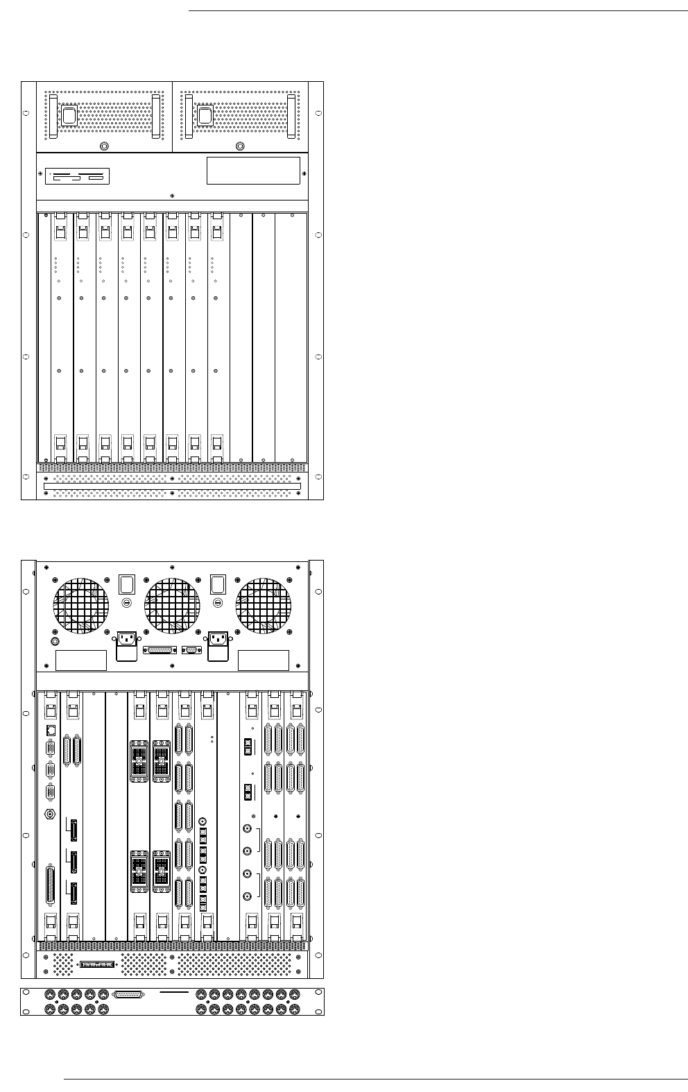
Centuri Processor Crate
(Front View)
Centuri Processor Crate
(Rear View)
Access to:
PSUs
Removable media drive
DSP cards
I/O Cards (Mic or Digital*)
Access to:
CPU card
Console interface card
GPI/O card
Routing/Link card (fitted with 2 Fibre Link ports)
I/O Cards (Analogue, Digital or Mic*)
DAW Midi interface panel
*special order only
NB. Cards shown are an example.
Configuration will vary according to
specification.
+3.3V+5V+5.5V+15V-15V
O
I
+3.3V+5V+5.5V+15V-15V
O
I
+5V
+3V3
FLAG 1
FLAG 12
RESET
Solid State Logic
O X F O R D • E N G L A N D
+5V
+3V3
FLAG 1
FLAG 12
RESET
Solid State Logic
O X F O R D • E N G L A N D
+5V
+3V3
FLAG 1
FLAG 12
RESET
Solid State Logic
O X F O R D • E N G L A N D
+5V
+3V3
FLAG 1
FLAG 12
RESET
Solid State Logic
O X F O R D • E N G L A N D
MMC + SD SmartMedia
Memory Stick
Compact Flash
+5V
+3V3
FLAG 1
FLAG 12
RESET
Solid State Logic
O X F O R D • E N G L A N D
+5V
+3V3
FLAG 1
FLAG 12
RESET
Solid State Logic
O X F O R D • E N G L A N D
+5V
+3V3
FLAG 1
FLAG 12
RESET
Solid State Logic
O X F O R D • E N G L A N D
+5V
+3V3
FLAG 1
FLAG 12
RESET
Solid State Logic
O X F O R D • E N G L A N D

The Centuri Processor
The Centuri processor is a 15U high 592mm deep rack unit. Cards are fitted to the front and rear of the chassis so space
for access is essential. See page 10 for chassis dimensions and minimum service clearance.
At the front of the processor are located the plug-in PSU units. One unit is capable of powering the system and a second
module may be ordered to provide power redundancy.
The panel below the power supplies is fitted with the Compact Flash memory card reader. This is used to transfer system
software onto the internal hard disk. Note that although a multiformat card reader is fitted, only the Compact Flash card
format is currently supported. The system’s hard-drive is located behind this panel. A second, redundant hard-drive can be
specified as an option. If this feature is ordered, a second identical drive, which also contains the system software, is fitted
and a front panel key switch is provided for disk selection.
Below the drives is the front card-cage which has space for 11 plug-in cards, numbered from left to right. The cards are
arranged as follows:
Slots 1–4 Channel DSP cards.
Slot 5 Always fitted with a master DSP card for mix processing.
Slot 6 Optional 2nd master DSP card for enhanced 2Fs bus capacity and processing.
Slots 7–10 Can be a combination of additional DSP cards and/or micamp cards (digital or MADI cards to
special order only)†.
Slot 11 Always blank.
There rear of the processor has space for 12 plug-in cards. Note that these slots are numbered from right to left.
Slots 1–4 Available for I/O cards (analogue, digital and MADI).
Slot 5 Always fitted with the console’s Routing/Link card.
Slot 6 Reserved for the optional GPI/O card.
Slots 7–10 I/O cards – analogue, digital and MADI (mic cards to special order only)†.
Slot 11 Always fitted with the Console-Interface card.
Slot 12 Always fitted with the CPU card.
Note that front and rear mounting I/O cards, although functionally identical, are physically different so it is not possible to
exchange cards between back and front.
At the rear of the rack is the connector for the DAW interface panel. When the DAW control option is specified a separate
1U Midi breakout panel and connecting lead is provided. See page 45 for additional information.
† Specifying rear mounted micamp cards or front mounted digital/MADI cards will extend the order lead time.
System Components
Section 4
Page 15
Page 16
C300HD Installation Guide
ETHERNET
VIDEO 3
VIDEO 2
SYNC
VIDEO 1
960XA
SERIAL
+5V
+3V3
FLAG 1
FLAG 12
RESET
Solid State Logic
O X F O R D • E N G L A N D
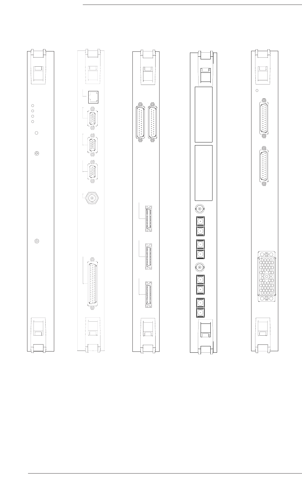
DSP CARD
901XA
MACHINE
CONTROL
TIME
CODE
CONTROL
SURFACE 1
CONTROL
SURFACE 2
CONTROL
SURFACE 3
906XA
IN 1
OUT 1
IN 2
OUT 2
W/CLK
IN 3
OUT 3
IN 4
OUT 4
W/CLK
909XN
CPU
Card
Console
Interface
Card
Routing/Link
Card
Shown equipped with
two Madi fibre ports
+5V
1-6
7-12
SPLIT OUTPUTS
MIC IN
1 - 12
908XA
A
Microphone
Input
Card
DSP
Card

Centuri – DSP Card
The DSP cards supply the signal processing function for the Centuri system. Each card provides 32 channels of processing
at 48kHz. or 16 channels of processing at 96kHz. DSP cards are all the same and do not require configuration. They can
therefore be fitted into any of the appropriate slots in the front of the Centuri rack.
Centuri – CPU Card
The Centuri Processor is always equipped with a CPU card. It can only be fitted to the left-most rear slot.
The CPU card is fitted with connectors for access to the following functions:
‘Ethernet’ 100baseT console network(1)
‘Video 1’ Display output for the Centre Section monitor (Video 2 and 3 are unused).
‘Sync ‘ Video sync input.
‘Serial’ 62-pin connector providing eight RS422/RS232 serial ports. An adaptor cable breaking out to eight
off 9-way D-type male connectors, labelled ‘TTY-A’ to ‘TTY-G’, is provided.
TTY-A, B, C, D and H: - machine control 1–5 (RS422)
TTY-E: - Console (RS232) – Connection for data terminal
TTY-F and G - Unused on C300
(1) The Ethernet connection is used for SSL control information, it is not TCP/IP protocol. Do not combine with proprietary
networks. Standard Ethernet repeaters can be used.
Centuri – Console Interface Card
The Centuri Processor is always fitted with one Interface card. It must be fitted to the rear of the card-cage next to the
CPU card.
The card provides the connection to the console’s control surface and handles all switch and lamp signals. Of the three
‘Control Surface’ connectors, only numbers 1 and 2 are used as these contain sufficient capacity for the largest C300HD
console.
This card also provides the connectors for parallel machine control and analogue timecode.
Centuri – Routing/Link Card
The Centuri is always fitted with a Routing/Link card. It must be fitted to the rear card-cage in position 5.
This card has two functions. The first is an internal function to manage the audio routing across the system’s backplane.
The second is to provide an interface for up to four optional MADI fibre ports. These ports provide access to remote SSL
Stageboxes or can be used as synchronous MADI I/O ports. Each port is equipped with a main and a redundant duplex
fibre connection. Links default to 64/32 Channel mode with 96K framing at 2Fs. Internal links on each card can be set to
force 56/28 channels or Legacy (48K) framing at 2Fs. In addition, each fibre interface provides an output of system Word
Clock on a separate BNC connector.
The audio Madi ports are available in either multimode or singlemode versions. A multimode version can be used for cable
lengths of up to 550m and the singlemode version for up to 2km. Fibre cables are not provided.
The fibre interface cards are cost options and should be specified at the time of order.
Centuri – Micamp Card
The Microphone input card (generally known as the BMA or ‘Broadcast Mic Amp’) provides 12 input channels. The input
is via a female Varicon (EDAC) connector. Mating connectors can be supplied as a cost option.
Each of the mic inputs has a buffered split output. The buffering takes place after the input pad, the RFI filter and the 25KHz
low-pass filter but before the variable gain stage. The split output has a gain of 26dB above the mic input level (or 6dB with
the pad in circuit) but is unaffected by the consoles’ mic gain setting. The split outputs are available on two female 25-way
D-type connectors.
Micamp cards are normally fitted to the front of the Centuri. If more than 48 channels are required then rear mounting
cards can be specified as a special order. Refer to section C for connector pinouts.
System Components
Section 4
Page 17
Page 18
C300HD Installation Guide
IN
OUT
1 - 12
13 - 24
25 - 36
37 - 48
49 - 60
1 - 12
13 - 24
25 - 36
37 - 48
49 - 60
GPI
907XA
IN
OUT
WORD
SYNC
IN
OUT
AES
SYNC
Tx
Rx
Tx
Rx
LOCK
A
LOCK
B
MADI
902XC
A1
A1
ANALOGUE IN
1 - 24
ANALOGUE OUT
1 - 24
904XA
9 - 16
1 - 8
25 - 32
17 - 24
AES/EBU IN
9 - 16
1 - 8
25 - 32
17 - 24
902XB
AES/EBU OUT
IN
OUT
WORD
SYNC
IN
OUT
AES
SYNC
Tx
Rx
Tx
Rx
LOCK
A
LOCK
B
MADI
902XD
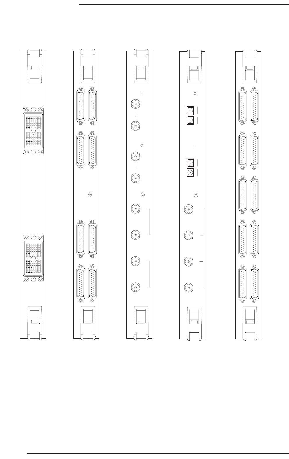
Digital I/O
Card
MADI I/O
Card
Copper version
MADI I/O
Card
Fibre version
GPI I/O
Card
Analogue I/O
Card

Centuri – Analogue I/O Card
The Analogue card provides 24 channels of balanced line-level input and output. At least one Analogue card will need to
be included to feed the monitor speakers as the post monitor-pot signals are only assignable to analogue outputs. The
connectors used are Canon DL96 types. Mating connector kits and a contact crimp tool can be supplied (as cost options).
Analogue cards are fitted at the rear of the Centuri chassis.
See page 57 for the DL pinout.
Centuri – Digital I/O Card
The Digital I/O card is available in two versions: 110Ω and 75Ω . Both types provide 64 channels (32 AES/EBU pairs) of
digital input and output. The 110Ω card is equipped with balanced input and outputs whereas the 75Ω card is unbalanced
for correct matching to coaxial cables. A breakout panel is available as an option for the 75Ω card – this converts D-25
connectors to chassis BNC plugs and comes with 1m connecting looms. These panels should be mounted behind the
Centuri rack; they cannot be remotely located because the linking cables are unbalanced.
Sample rate conversion is available on every input so the card can accept input rates from 32kHz to 96kHz. Sample Rate
Conversion is also available on all outputs, either at any of the available System sample rates (Fs or 2Fs) or locked to a
nominated AES input on the same card. If the VSR option is fitted (see page 11), any AES input can be selected as the System
sample clock. The connectors are all D-25 type females and mating connectors can be supplied.
Digital cards are fitted at the rear of the Centuri chassis.
Centuri – Madi Card (Copper version)
The MADI I/O card can be configured to operate in 56/64 channel mode at Fs or in 28/32 channel mode at 2Fs. Both
Legacy (Fs) Framing* and Standard (2Fs) framing modes are available at 2Fs sample rates. The 56/28 channel mode supports
Fs ±12.5% varispeed operation. The 64/32 Channel mode will accept ±0.1% variations in sample frequency.
*Only synchronous 2Fs MADI signals with legacy framing are supported and any Word Clock or AES sync signal must be
disconnected from the MADI card or the audio will be muted.
Both Word Clock and unbalanced AES-3id sync inputs and outputs are provided. If the incoming MADI signal is synchronous
(i.e. derived from a device locked to the same reference as the C300HD processor core), then no external sync signal is
required. If, however, a valid Word Clock or AES sync signal is connected, the card will automatically default to using the
external sync reference to decode the MADI data stream. The Sync output signal always follows the current MADI sync
reference source and can be used to clock any connected device that requires a MADI/AES sync reference.
The MADI card includes input and output sample rate conversion which offers the same functionality as the Digital I/O
card except that the Word Clock input is used as the reference for Output sample rate conversion and is also required if
sample rate conversion is to be used on the MADI input.
The card is fitted with dual connections – MADI A and MADI B. The outputs are duplicates of the MADI signal so that a
safety backup can be made without having to use external distribution. For the inputs, MADI A has priority but MADI B
will become active if the A signal is lost. Refer to page 33 for further interfacing details.
Centuri – Madi Card (Fibre version)
Operates in exactly the same way as the copper version but the MADI connectors are now singlemode or multimode SC
optical types. The fibre type must be specified at time of order.
Centuri – GPI/O Card
The optional GPI/O card provides 60 GPI inputs and outputs. Inputs (which can trigger many console functions including
channel faders and cuts) are opto-isolated. The outputs are provided by relay closure. Access is via 25-pin D-type
connectors; inputs are male and outputs are female.
Only one GPI/O card can be fitted to the Centuri rack.
System Components
Section 4
Page 19
Page 20
C300HD Installation Guide
+48V
SIG
OVER
LOAD
SELECT
+48V
SIG
OVER
LOAD
SELECT
+48V
SIG
OVER
LOAD
SELECT
+48V
SIG
OVER
LOAD
SELECT
+48V
SIG
OVER
LOAD
SELECT
+48V
SIG
OVER
LOAD
SELECT
+48V
SIG
OVER
LOAD
SELECT
+48V
SIG
OVER
LOAD
SELECT
PUSH
PUSH
PUSH
PUSH
PUSH
PUSH
PUSH
PUSH
PSU 1
AC
DC
PSU 1
AC
DC
STANDBY
ON
SELECT
TERMINAL
NETWORK
CH1
CH2
CH3
CH4
SELECT
LEVEL
MONITOR
TALKBACK
SELECT
(YES)
(NO)
MENU
Solid State Logic
O X F O R D • E N G L A N D
+48V
SIG
OVER
LOAD
SELECT
+48V
SIG
OVER
LOAD
SELECT
+48V
SIG
OVER
LOAD
SELECT
+48V
SIG
OVER
LOAD
SELECT
+48V
SIG
OVER
LOAD
SELECT
+48V
SIG
OVER
LOAD
SELECT
+48V
SIG
OVER
LOAD
SELECT
+48V
SIG
OVER
LOAD
SELECT
PUSH
PUSH
PUSH
PUSH
PUSH
PUSH
PUSH
PUSH
+48V
SIG
OVER
LOAD
SELECT
+48V
SIG
OVER
LOAD
SELECT
+48V
SIG
OVER
LOAD
SELECT
+48V
SIG
OVER
LOAD
SELECT
+48V
SIG
OVER
LOAD
SELECT
+48V
SIG
OVER
LOAD
SELECT
+48V
SIG
OVER
LOAD
SELECT
+48V
SIG
OVER
LOAD
SELECT
PUSH
PUSH
PUSH
PUSH
PUSH
PUSH
PUSH
PUSH
+48V
SIG
OVER
LOAD
SELECT
+48V
SIG
OVER
LOAD
SELECT
+48V
SIG
OVER
LOAD
SELECT
+48V
SIG
OVER
LOAD
SELECT
+48V
SIG
OVER
LOAD
SELECT
+48V
SIG
OVER
LOAD
SELECT
+48V
SIG
OVER
LOAD
SELECT
+48V
SIG
OVER
LOAD
SELECT
PUSH
PUSH
PUSH
PUSH
PUSH
PUSH
PUSH
PUSH
+48V
SIG
OVER
LOAD
SELECT
+48V
SIG
OVER
LOAD
SELECT
+48V
SIG
OVER
LOAD
SELECT
+48V
SIG
OVER
LOAD
SELECT
+48V
SIG
OVER
LOAD
SELECT
+48V
SIG
OVER
LOAD
SELECT
+48V
SIG
OVER
LOAD
SELECT
+48V
SIG
OVER
LOAD
SELECT
PUSH
PUSH
PUSH
PUSH
PUSH
PUSH
PUSH
PUSH
+48V
SIG
OVER
LOAD
SELECT
+48V
SIG
OVER
LOAD
SELECT
+48V
SIG
OVER
LOAD
SELECT
+48V
SIG
OVER
LOAD
SELECT
+48V
SIG
OVER
LOAD
SELECT
+48V
SIG
OVER
LOAD
SELECT
+48V
SIG
OVER
LOAD
SELECT
+48V
SIG
OVER
LOAD
SELECT
PUSH
PUSH
PUSH
PUSH
PUSH
PUSH
PUSH
PUSH
IN 3
OUT 3
IN 4
OUT 4
W/CLK
C-SB Stagebox
(Front View)
48 inputs
48 Split outputs
16 Line outputs
4 GPI I/O
Single or dual Fibre Link

C-SB Stagebox (option)
The C-SB is a Mic/Line input/output stagebox which can be located remotely from the Centuri chassis. The C-SB can
operate at all C300HD sample rates but is currently restricted to 32 channels when operating at 2Fs. Each CS-B is a 14U
high, 462mm deep, rack-mounted unit.
At the front of the rack are nine slots for plug-in cards: six slots for mic/line input cards; two slots for line output cards
and one for the CPU card. At the rear is an auto-ranging switch-mode power supply. This will accept input voltages from
100–240v without adjustment. The PSU units provide two unswitched mains outlets via IEC 6A shuttered sockets. A 2nd
power supply unit may be fitted to provide redundancy
Each micamp input card is equipped with 8 channels, therefore a C-SB rack may be fitted with from 8 to 48 mic inputs. The
line output card also provides 8 channels and in addition features 4 channels of GPI relay closure. The CPU card is fitted
with a headphone socket to allow local monitoring of sources and also provides four analogue outputs via a 25-way D-
type connector. These outputs are assigned from the console and may be used for additional analogue feeds such as
talkback or SLS.
Each mic input is provided with a split output. This output functions in the same way as the BMA circuit. (ie. post pad, limiter
and 26dB buffer but pre the variable gain stage). The split outputs are available on 25-way D-type male connectors.
Remote stageboxes are connected to the Centuri core by using duplex fibre-optic cable(1) for the Madi audio data (referred
to as a GLink in the software) and a separate Ethernet cable(2) for the control functions (gain, pad, filter etc.). The audio
fibre links to a stagebox can be duplicated thus creating audio redundancy for critical or on-air reliability. The number of
Madi links required for the Centuri rack should be specified at the time of order.
The standard unit is fanless and so can be located within the live production area – subject to the following note. A low-
noise fan ventilation kit is available as an option.
The stagebox racks are cooled by convection at the front of the rack. The air flow from bottom to top of the front panel
must not be obstructed in any way (cable guides are provided at each side to route cables away from the air intake). The
air temperature at the intake and at the rear PSU heatsinks MUST NOT exceed 30° Centigrade.
Special considerations need to be observed when fitting stageboxes into flight cases – refer to Appendix F.
(1) The fibre optic cable is available in two types: for distances of up to 550m (multimode fibre) and distances of up to 2Km (singlemode
fibre).
(2) The standard maximum limit for Ethernet cable is 100m. For distances of over 100m Ethernet repeaters may be needed. Alternatively,
the Ethernet cable can be converted to fibre. This can then run the same distances as the audio fibre. Please discuss specific
requirements with SSL’s Project Engineering Department.
System Components
Section 4
Page 21
Page 22
C300HD Installation Guide
Solid State Logic NetBridge
SERIAL 1 - 8
TERMINAL
SERIAL 9
230
SSL
TCP/IP
Model
Serial No.
Solid State Logic
Oxford • England
FUSE risk of fire, use same type
and rating
(IEC 127)
250V
250V
Ratings: AC ~ 50/60Hz
Volts
Amps
626755X4
90-125 1.2-0.9
195-255 0.6-0.5
10A(T)
5A(T)
DATE
INITIALS
TESTED
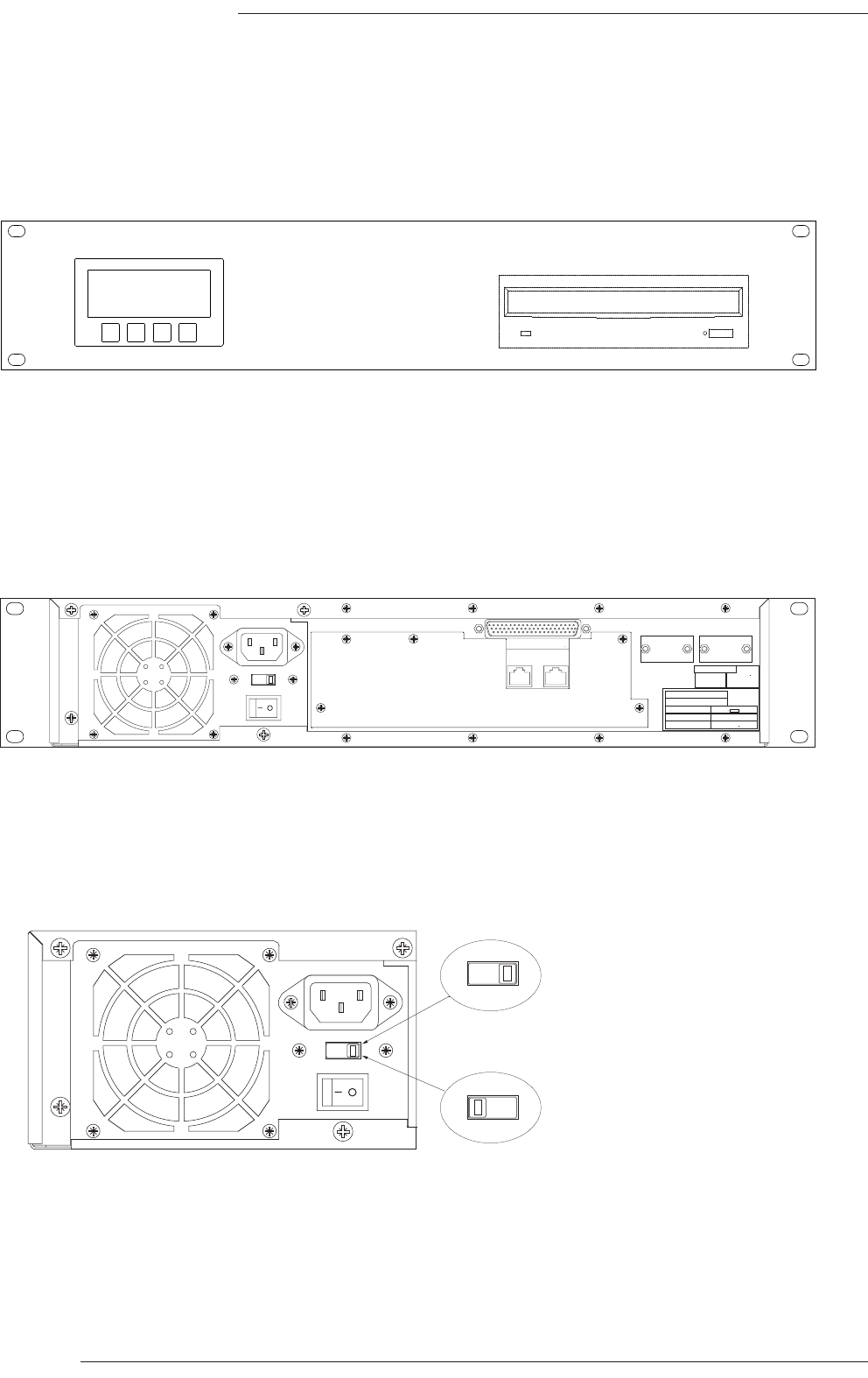
NetBridge (Front View)
NetBridge (Rear View)
NetBridge - PSU Voltage Selection
Voltage select switch shown in
the 230V position
Voltage select switch shown in
the 115V position
230
230
115

NetBridge (option)
NetBridge is a 2U rack mounting unit.
The NetBridge provides two main features. Firstly (as the name suggests) it is a bridge between the proprietary Solid State Logic
network, and the standard TCP/IP protocol, allowing remote diagnostic connection over the Internet. Up to 7 diagnostic ports
may be served by a single NetBridge unit, with secure log-in facilities enabling trained staff or SSL engineers to access
diagnostic functions remotely from any location worldwide.
Do not combine the SSL network and the facility’s TCP/IP network; they are different protocols.
Secondly it can be used to transfer data files between the C300HD console to which it is dedicated and the ‘SSL-Network’ central
file server (CFS). This allows C300HD session templates (used for offline configuration) and project archives to be moved across
the Internet without requiring access to the console’s CPU.
Using the secure login access provided by NetBridge, users may upload a console template to a secure website, edit the
configuration offline and then reload their profile prior to the production saving valuable setup time. Parameters available
for offline configuration include fader strip allocations, channel names and type, bus routing assignments, processing order,
output options and fader grouping setup.
NetBridge requires access to the facility’s internet service. To do this, an Ethernet connection will be required. The
NetBridge will also need permission to access the SSL Network secure server; this may require the configuration of any
firewall software that may be in use. (See page 39 for further information.)
NetBridge does not have dual power supplies as it is not critical to console operation.
NetBridge is not fitted with an auto-ranging power supply and the input setting must be confirmed before applying power.
The voltage select switch is located on the rear of the PSU unit, see opposite for switch location.
To change the setting:
1. Switch off and remove the IEC lead.
2. Using a small flat-bladed screwdriver, slide the select switch so that the appropriate voltage is indicated.
System Components
Section 4
Page 23
I/R
K/B
VIDEO
IN
MSD
DIAG
PHASE
SCOPE
REMOTE
POWER IN D1 D2 D3 D4 D5 D6 D7 D8
EXT T/B
MIC IN
TALKBACK
OUTPUT
PUSH
Page 24
C300HD Installation Guide
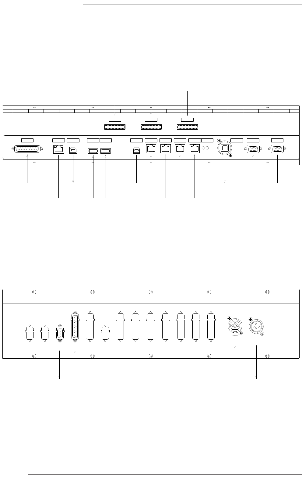
CTRL USB IN1 USB IN2 K/BOARD USB OUT
VU MTRS ETH CTRL ETHER 2 VID 1 VID 2ETHER 1 ETHER 3 ETHER 4 MIC/GN
CTRL 3
CTRL 2
CTRL 1
Location of Console Connectors
Location of Audio Connectors
Console control
Analogue meter
inputs (option)
USB soft-
key data
Softkey
data in
Phasescope
diagnostics
(option)
Phasescope
digital input
(option)
TB mic
in
TB out
USB hub
in
USB kbd
& bitpad
data Console Ethernet hub
USB hub
out
Centuri
SXGA
Alt.
SXGA
Unused

External Keyboard / KVM Switch
There is an inbuilt USB trackball and keyboard included with the C300HD system. These can be used for normal control
of the console’s mixing and naming functions.
The C300HD console also contains additional hardware that allows its trackball/keyboard to be
used to control an external workstation and the console monitor may be used to display the
workstation’s video output. The switches that control the keyboard and video selection are
located on the surround of the monitor section’s LCD screen. The switches may be operated
individually or can be electronically linked – by pressing both down together – to simplify
operation.
‘EXT VID’ selects between the two SXGA inputs on the connector panel, ‘VID 1 and ‘VID 2’. ‘VID
1’ is normally connected to the Centuri Core. ‘VID 2’ is available for connection to an external
SXGA input from a PC or Mac. Maximum supported resolution is 1280 x 1024.
‘EXT K/B’ routes the output from the USB connector mounted in the Keyboard drawer either to the console’s processor
or to the Type B USB connector on the connector panel marked ‘K/BOARD’. This enables the keyboard and any connected
pointing device (Mouse, Trackball etc.) to be routed to an external PC or MAC.
A further Type B USB connector marked ‘CRTL’ carries USB Keyboard data generated via Console Soft Keys. This can also
be routed to a MAC or PC and used to control a DAW via its supported Keyboard short commands supplementing the
existing MIDI DAW control offered on C300. The standard connector panel includes a two port USB hub to simplify
installation by allowing the simulated USB keyboard data to be merged with the commands from the physical keyboard
connected to the console with a single USB link to the PC or MAC running the DAW software.
Two USB A-B cables are supplied with the console to connect the ‘CTRL’ and ‘K/BOARD’ USB outputs to the hub inputs.
Script Tray (option)
The script tray is a movable transparent panel which fits over a channel bay. It is fitted with rollers to allow it to be moved
along straight sections of the console.
A script tray can be added at any time as it does not require modifications to the console.
Loudspeaker Shelf (option)
A flat secure shelf is available for the positioning of loudspeakers, monitors etc. Each shelf is 400mm wide by 253mm deep.
A supporting rail is fixed to the console back panel for each speaker shelf. Additional support rails can be fitted so that
shelves may be moved to different positions along the console.
TFT External Input (option)
This option allows any of the channel bay TFT screens to be switched to show an external XGA (1024x768) video signal.
The switchover may be effected either by a GPI closure triggered from a free button or by a dedicated switch which can
be mounted on a custom panel. This option must be specified at time of order. The input will be via an HD15-pin female
connector mounted into one of the blanks on the Audio connector panel.
System Components
Section 4
Page 25
EXT
K/B
EXT
VID
Page 26
C300HD Installation Guide
b a
3
2
1
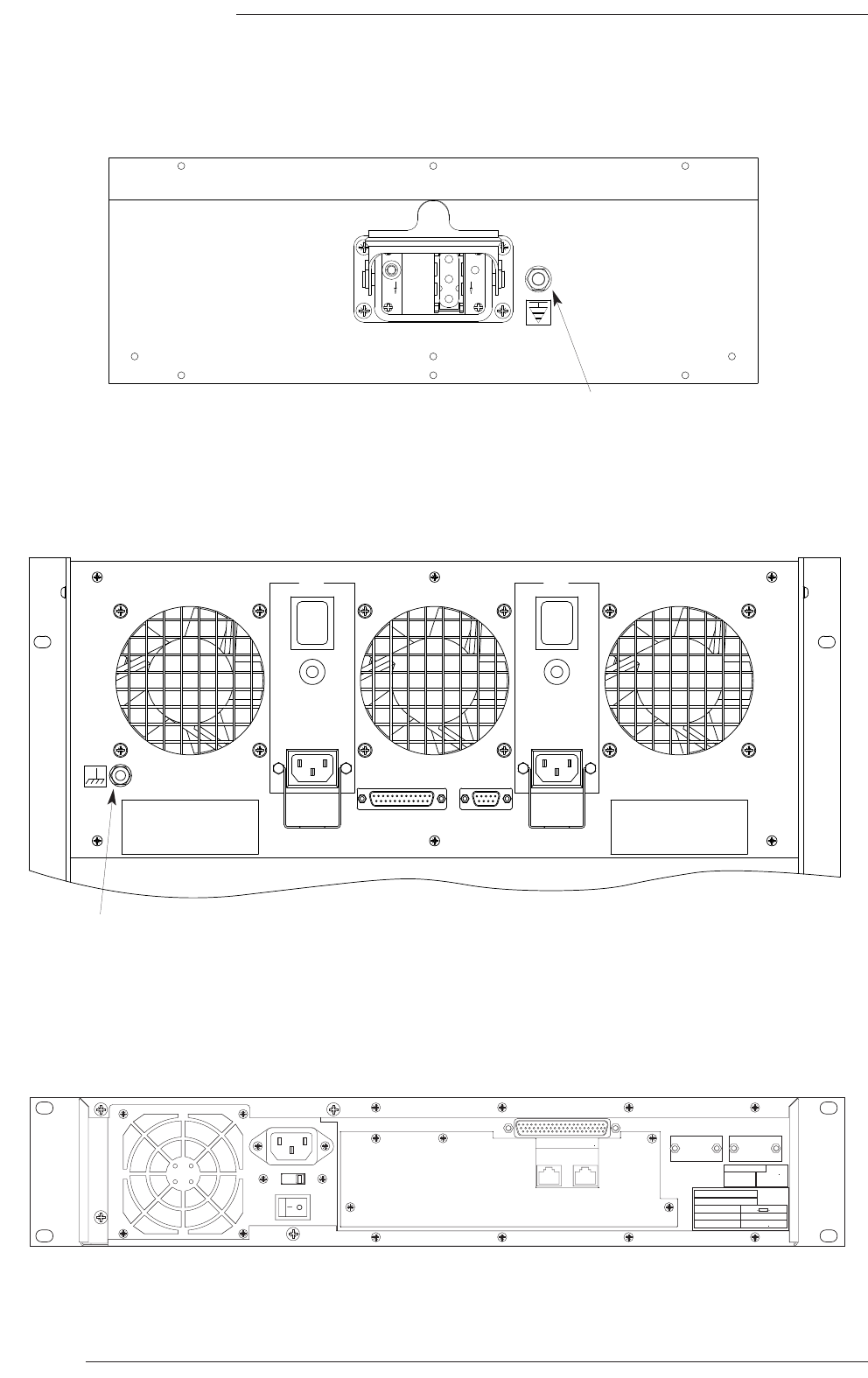
Console Mains Inlet Panel
Centuri Mains Inlet Panel
NetBridge Rear Panel
I
O
I
O
CONSOLE
POWER
INDICATORS
REMOTE
POWER
INDICATORS
PSU 1 PSU 2
SERIAL 1 - 8
TERMINAL
SERIAL 9
230
SSL
TCP/IP
Model
Serial No.
Solid State Logic
Oxford • England
FUSE risk of fire, use same type
and rating
(IEC 127)
250V
250V
Ratings: AC ~ 50/60Hz
Volts
Amps
626755X4
90-125 1.2-0.9
195-255 0.6-0.5
10A(T)
5A(T)
DATE
INITIALS
TESTED
Chassis Bolt
Chassis Bolt

Section 5 – Installation Wiring
This section provides the details for connecting the system components together.
Power Supply Connections
This section refers to the following supplied cables :
Description SSL Part No. qty Notes
Con IEC Free Socket 6A 2m 32VGL362 2 Centuri
Cable Power Digital 2m 32VALXVX 2 Main & Redundant Console power
Lead Chassis Earth 16m 66C93115 1 Console to Centuri
a) Connect the mains input lead to a suitable supply outlet.
THE MAINS SAFETY EARTH MUST BE CONNECTED
For systems where PSU redundancy is specified – Connect both the console’s Harting mains leads to
independent mains supplies. For live transmission work it is recommended that one of the power sources be from
an un-interruptable source. The console is fitted with auto-ranging power supplies which will accept mains voltages
which range from 100 to 240V without adjustment.
THE TWO POWER SOURCES MUST NOT BE FROM DIFFERENT PHASES OF A 3-PHASE SUPPLY.
b) Connect the Centuri’s IEC lead(s) to appropriate mains supply outlet(s). If a redundant PSU module is specified refer
to the notes above for suitable supply provision.
The Centuri crate is also fitted with auto-ranging power supplies which will accept mains voltages which range from
100 to 240V without adjustment.
c) If specified, do not connect a source of power to the NetBridge until the voltage select switch position has been
confirmed. The NetBridge operates at either 115V or 230V ranges and its power supply must be set to the
appropriate range for the local supply.
Refer to the diagram on page 22 for the location of the voltage select switch.
d) Earth Wiring – A chassis to chassis earth cable needs to be installed between the console and the processor.
This keeps the two earths at the same potential thus preventing currents flowing along the signal cables.
Run the green chassis earth cable from the Console’s chassis bolt to the similar earth bolt located on the Centuri
backpanel.
Installation Wiring
Section 5
Page 27
Page 28
C300HD Installation Guide
960XA
MACHINE
CONTROL
TIME
CODE
CONTROL
SURFACE 1
CONTROL
SURFACE 2
CONTROL
SURFACE 3
906XA
SYNC
VIDEO 3
VIDEO 2
VIDEO 1
ETHERNET
SERIAL
CTRL USB IN1 USB IN2 K/BOARD USB OUT
VU MTRS ETH CTRL ETHER 2 VID 1 VID 2ETHER 1 ETHER 3 ETHER 4 MIC/GN
CTRL 3CTRL 2CTRL 1
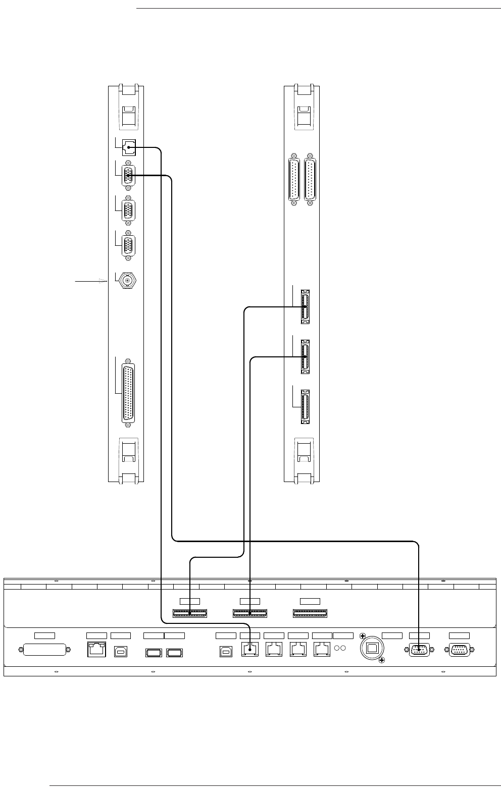
Control Surface Wiring - Block Diagram
CPU Card Control Card
Console
Connector Panel
Front Panel
cables x 2
XGA video
lead
RJ45 Ethernet
lead
Sync connector

Centuri to Console Surface Connections
This section refers to the following supplied items:
Description SSL Part No. qty Note
Lead RJ45 Shielded 15m 66C67316 1
Lead Video HD15W D-Type 16m 66DN(16)V1 1 (20)=20m, (25)=25m, (48)=48m
Loom 36-way H/D Digital 14m 66CNA0(14)2 24, 44, 64 and 98m options only
Terminator plug 75 32TKB7TC 1
BNC 75Ω TEE Adaptor 32TKU7CC 1
a) Front Panel Cables
Locate the two MDR–MDR front panel cables and connect them between the Centuri Control card and the console
interface panel as shown opposite. Although there are three connectors at both the Centuri and the console ends,
only connectors 1 and 2 are used.
These cables are symmetrical, having the same connectors at each end.
The front panel cables are only supplied in 14, 24, 44, 64 or 98m lengths. This is due to a timing requirement for the
high speed serial data. Do not attempt to shorten these cables. The connectors on these cables are not removable.
b) Network Cable
The Centuri processor uses an RJ45 Ethernet network to communicate with the C300HD console, Stageboxes and
NetBridge. The console has a built-in 4-way Ethernet repeater.
Connect the Ethernet lead between the Centuri CPU card and any of the four ‘Ether’ sockets beneath the console.
If Netbridge is specified then a second RJ45 Ethernet lead will be supplied with the system. This lead is connected
between the console and the ‘SSL Network’ connector on the NetBridge rear panel.
c) Video Cable
There are three video outputs available on the CPU card. Video 2 and Video 3 are static background displays. Video
1 is used for the Monitor section display. The video output is XGA standard – 1024 x 768 @ 60Hz. The connectors
are high-density 15-pin D-type (HD15).
Connect the video cable as shown in the diagram opposite. The cable is male-male so does not have to be run in a
particular direction.
It is not recommend that the supplied video cable be extended. Doing so may reduce the image quality as the cable is
matched to function over long runs; the cables are of a high quality individually screened type. Longer cables are available
to order.
d) Sync Cable
Connect the source of black-and-burst (or composite) or Tri-sync video to the SYNC IN connector on the processor
crate using the T-adaptor and 75Ω terminator supplied to provide cable termination.
Installation Wiring
Section 5
Page 29
Page 30
C300HD Installation Guide
+5V
1-6
7-12
SPLIT OUTPUTS
MIC IN
1 - 12
908XA
A
A1
A1
ANALOGUE IN
1 - 24
ANALOGUE OUT
1 - 24
904XA
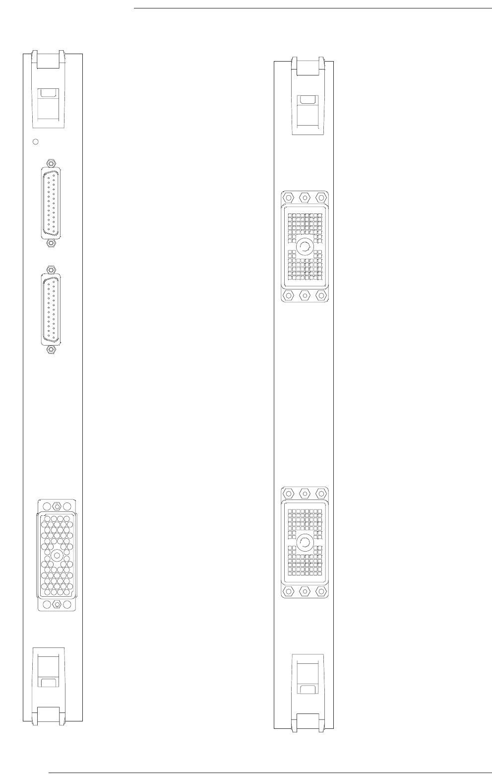
Micamp Input Card Analogue I/O Card
Split Output Connectors
25-pin D-type female
Microphone input Connector
Varicon 56-way female
Analogue Input Connector
DL96 female
Analogue Output Connector
DL96 female

I/O – MicAmp Card (SSL ref. 908)
Each MicAmp Input Card contains 12 Microphone circuits. The inputs are accessed via a Varicon (aka. EDAC or Elco) 56-
way female connector.
The split outputs are accessed via two 25-pin D-type female connectors.
Refer to Appendix C for the connector pinouts.
SSL is able to supply mating connectors if requested, (at additional cost).
If more than one micamp card is fitted then the card furthest to the right will have the lowest input number and the channel
numbers will increment by 12 as each card is added. Any cards added subsequently, should be placed to the left of any
existing cards otherwise the channel numbering will be altered.
I/O – Analogue input/output Card (SSL ref. 904)
The Analogue Card provides 24 circuits of electronically balanced input and output. These circuits are accessed via Canon
DL 96 way female connectors; mating connectors are available to order
Refer to Appendix C for the connector pinouts.
As is the case for the MicAmp, cards added subsequently should be placed to the left of existing cards.
The default line-up level for analogue I/O is 0dBFS = +18dBu. This level may be globally altered and can range from +9dBu
to +24dBu. The value can be adjusted from a setup screen to match the standard operating level for the facility.
When assigning analogue output channels as insert sends, the routing system will automatically assign the same input
channel number as the corresponding return. It is therefore necessary to physically wire outboard equipment so that
circuit allocation follows this arrangement.
Installation Wiring
Section 5
Page 31
Page 32
C300HD Installation Guide
9 - 16
1 - 8
25 - 32
17 - 24
AES/EBU IN
9 - 16
1 - 8
25 - 32
17 - 24
902XB
AES/EBU OUT
IN
OUT
WORD
SYNC
IN
OUT
AES
SYNC
Tx
Rx
Tx
Rx
LOCK
A
LOCK
B
MADI
902XC
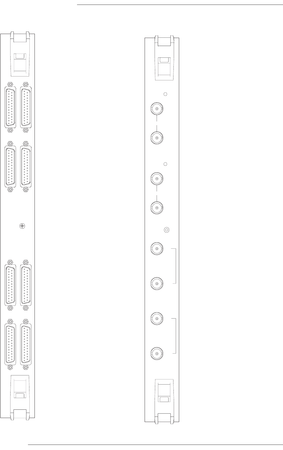
Digital I/O Card MADI I/O Card
(Copper version)
AES/EBU Output Connectors
25-pin D-type female
AES/EBU Input Connectors
25-pin D-type female
MADI Link A
BNC 75π
MADI Link B
BNC 75π
MADI Word Sync
BNC 75π
AES Sync
BNC 75π

I/O – Digital Input/Output Card 110Ω (SSL ref. 902XF)
The Digital Input Card provides 32 balanced AES/EBU signal pairs of input and output. All circuits are accessed via 25-pin
D-type female connectors.
Refer to Appendix C for the connector pinout for this card. Mating connector kits can be ordered for the card.
As in the case of the Analogue I/O, cards added subsequently should be placed to the left of existing cards.
When assigning digital output channels as insert sends, the routing system will automatically assign the same input
channel number as the corresponding return. It is therefore necessary to physically wire outboard equipment so that
circuit allocation follows this arrangement.
I/O – Digital Input/Output Card 75Ω (SSL ref. 902XJ)
This version of the Digital I/O card is externally identical to the 110Ω version (apart from its designation number). The
Impedance of each input and output circuit however, is now 75Ω and unbalanced for correct matching to installations using
co-axial cabling.
A separate BNC interface panel is available as a cost option. This is 2U high and is fitted with 64 chassis mounted BNC
plugs – 32 input and 32 output. 1metre D25–D25 interconnecting looms are provided. These looms should not be
extended beyond 1m as the signals are unbalanced and signal quality may be reduced.
As in the case of the Analogue I/O, cards added subsequently should be placed to the left of existing cards.
When assigning digital output channels as insert sends, the routing system will automatically assign the same input
channel number as the corresponding return. It is therefore necessary to physically wire outboard equipment so that
circuit allocation follows this arrangement.
I/O – MADI Card (SSL ref. 902XG copper version / 902XH/K fibre versions)
The MADI I/O Card can operate in 56 or 64 channel mode at Fs or in 28/32 channel modes at 2Fs. Both Word Clock and
AES-3id (unbalanced) sync inputs and outputs are fitted.
If the incoming MADI signal is synchronous, no additional sync reference is required. However if a valid Word Clock or AES
sync signal is connected, the card will automatically default to using the external sync reference to decode the MADI data
stream. A Sync reference is always required if the incoming MADI stream in asynchronous or if varispeed and/or sample
rate conversion is required.
The fibre optic versions of the card are available with singlemode or multimode connections. Ensure that the matching
cable type is used. The recommended maximum cable length for the singlemode version is 2km and for the multimode
version is 550m.
Installation Wiring
Section 5
Page 33

Page 34
C300HD Installation Guide
GPI I/O Card
IN
OUT
1 - 12
13 - 24
25 - 36
37 - 48
49 - 60
1 - 12
13 - 24
25 - 36
37 - 48
49 - 60
GPI
907XA
GPI input Connectors
25-way D-type Male
GPI output Connectors
25-way D-type Female
Installation Wiring
Section 5
Page 35
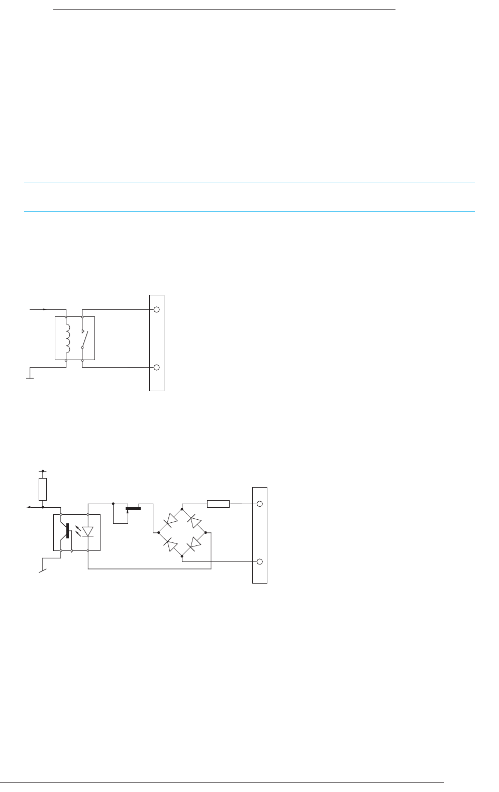
I/O – GPI I/O (SSL ref. 907XA)
The GPI I/O Card contains 60 circuits of opto-isolated input and 60 circuits of relay-closure output. Inputs are accessed
by 25-pin D-type male connectors and outputs by 25-pin D-type female connectors; mating connector kits are available to
order.
Both the input and output circuits are fully isolated from the processor electronics. On all output connectors, there is a
protected source of +15V available and a 0V reference is available on each input connector.
The input and output signals can be either latching or momentary. This setting is individually assigned in software via the
touch screen. When set to momentary the input signal duration must be greater than 50mS.
When used for track arming and tally, the tally must return to the same number input as the output signal, (ie. the tally
for GPI Out 1 will be on GPI In 1).
GPI Outputs
The switch closure is by DIL relay. Contact rating is 100Vdc, 125Vac, 100mA max. Do not use the output contacts to
directly switch capacitive or reactive loads, always use an external relay with a suitable contact rating.
GPI Inputs
The signal input requires AC or DC voltage between 4V and 30V. The current drawn is approximately 10mA.
GPI in
Input A
Input B
Contact A
Contact B
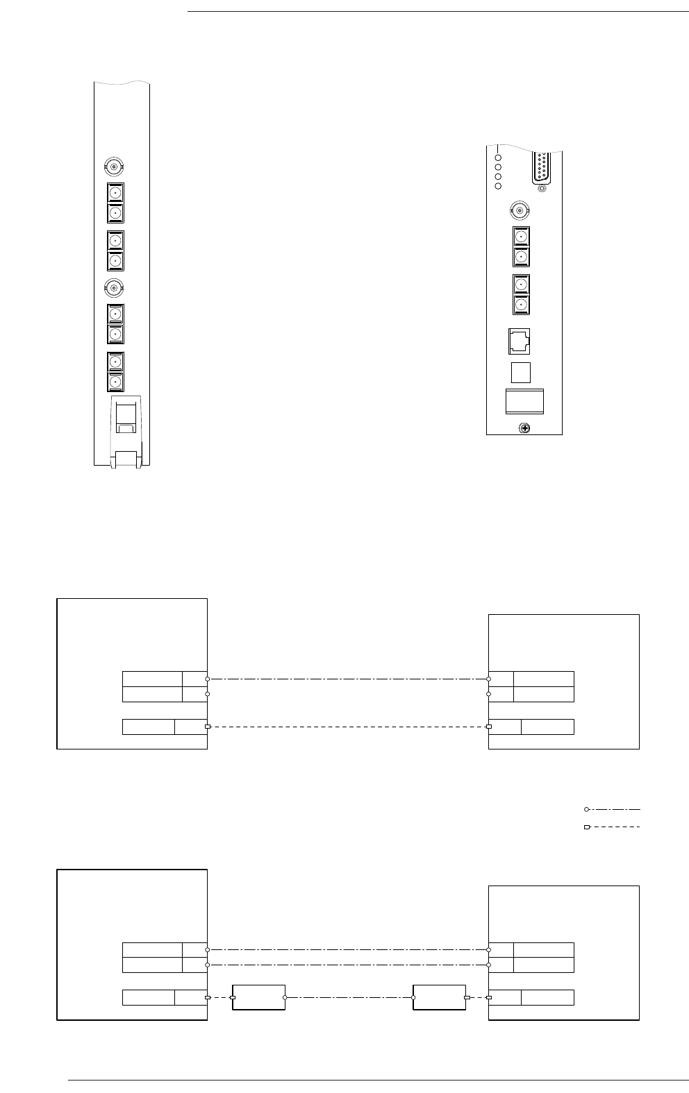
audio link (backup)
Stagebox
Centuri
Processor
audio link (main)
duplex fibre link
RJ45 ethernet
Media
converter
SC
Fibre i/f 1a
Network control link
RJ45
Stagebox
Centuri
Processor
SC
Fibre i/f 1b
Media
converter Network
RJ45
SC Fibre i/f 1a
SC Fibre i/f 1b
audio link
SC
Fibre i/f 1a
Network RJ45 Network
RJ45
SC Fibre i/f 1a
control link
SC
Fibre i/f 1b SC Fibre i/f 1b
Page 36
C300HD Installation Guide
IN 1
OUT 1
IN 2
OUT 2
W/CLK
IN 3
OUT 3
IN 4
OUT 4
W/CLK
909XN
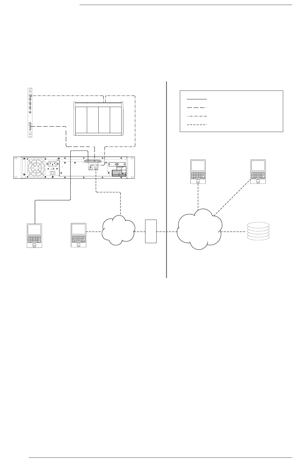
Centuri Link Card
Fitted with two redundant Madi
interfaces
Connection with UTP control link (100m max)
Duplex fibre (SC)
Ethernet (RJ45)
Redundant connection with fibre control link (>100m)
Stagebox CPU Card
TERMINAL
NETWORK
CH1
CH2
CH3
CH4
IN 3
OUT 3
IN 4
OUT 4
W/CLK
C-SB Connection Diagrams
Stagebox Madi Fibre Connectors and Panels

Stageboxes & Fibre Links
The C-SB Stagebox utilises fibre-optic Madi cable for audio connection between itself and the Centuri processor. This
provides the advantages of noise immunity, reduced weight and bulk of wiring and the elimination of earth loops. A separate
control signal (for gain, pad, filter switching etc.) is carried over the SSL Ethernet network – this control signal can be
converted into fibre for runs longer than 100m.
The cables required for audio connection are duplex fibre with SC connectors (flat not APC type). A redundant connection
will require a second cable. A 2m duplex lead is provided as standard with each stagebox. The interfaces may be specified
as multimode or singlemode fibre types. The maximum cable length for a multimode Madi connection is 550m, and for
singlemode is 2km.
Longer fibre cables and/or ruggedised OB cable using adaptor panels/patch panels may be available to order. SSL is able to
suggest a range of fibre solutions although the facility may prefer to provide its own fibre installation. Details of fibre
installation options should be discussed with SSL’s Project Engineering Department prior to the time of order.
When Stageboxes are specified, it is recommended that a 10/100 Ethernet hub/switch is installed so as to provide isolation
for the remote network connection(s). A 1U rack mounting 16-port switch is available to order.
When locating Stageboxes at distances greater than 100m from the Centuri rack the Ethernet control cable will have to
be buffered – using an Ethernet repeater/switch – or, ideally, converted to fibre by using proprietary media converters.
Up to four Madi fibre interfaces. The Centuri Routing card can be fitted with
The BNC connector associated with each Madi port provides an output of system Wordclock.
Installation Wiring
Section 5
Page 37
Page 38
C300HD Installation Guide
SERIAL 1 - 8 TERMINAL SERIAL 9
230
SSL TCP/IP
Model
Serial No.
Solid State Logic
Oxford • England
FUSE risk of fire, use same type
and rating (IEC 127)
250V
250V
Ratings: AC ~ 50/60Hz
Volts Amps
626755X4
90-125 1.2-0.9
195-255 0.6-0.5
10A(T)
5A(T)
DATE INITIA LS
TESTED
ETHERNET
VIDEO 3
VIDEO 2
SYNC
VIDEO 1
960XA
SERIAL
RS232 Diagnostics Cable
RS232 Terminal Cable
SSL Network
TCP/IP Network
Internal Network External Network
Maintenance
Access
NetBridge Installation
Operational
Access
TCP/IP
network
Firewall
SSL
Service
Freelance
Engineer
Central
File
Server
Internet
NetBridge
‘TTY-E’
C300HD Console
Centuri
CPU Card

NetBridge Installation
NetBridge has eight serial ports plus two Ethernet ports. The first Ethernet port is connected to the C300’s network. The
second port is for connection to the Internet; this can be via DHCP server (for a dynamically assigned IP address), or a
static IP address defined by the operator. The IP number (in ‘dot’ notation) will be shown on the front panel while the unit
is powered.
In facilities with a firewall to the Internet, this address is likely to be for internal use within the installation and not visible
to the outside world. For external diagnostic access, the firewall will have to be set to pass (and redirect) the appropriate
incoming traffic to the NetBridge unit, which will have to be agreed with and configured by the facility’s IT staff.
NetBridge operation is more fully described in a separate document which is supplied with the hardware.
Connection
The eight serial ports are all located on the single 62-pin connector (a breakout adaptor is provided). Serial ports 1 to 7
can be connected to the ‘Console’ port on the Centuri’s CPU card (on port TTY-E), allowing one NetBridge to have
terminal diagnostic access to up to seven C300HD processors.
Serial port 8 may be connected to a data terminal (or software terminal emulator) for permanent local diagnostic access
without requiring login. (see Appendix C for cable details)
Access
For security purposes, the NetBridge file transfer functions can only be accessed by one registered user who must be
logged into the Central File Server (CFS). This uses the secure HTTPS protocol, which must be passed through any firewall
(and redirected as required), although this is unlikely to cause any security concerns as it has 128bit Secure Socket Layer
encryption. For file transfer between the console and the CFS, the user must be logged in at the console itself. For file
transfer between the CFS and another computer (eg. authorised freelance engineer or SSL support staff), the user may
login from an Internet connection, with the same username and password security requirements.
Diagnostic access also uses ‘Secure Socket Layer’ encrypted login, and is available to multiple users simultaneously over the
TCP/IP network link. They can log-in as terminal users and each run the terminal client application on the NetBridge to
give them switched access to the seven serial ports.
File Transfer
If a console operator wishes to export a session template to the CFS so that others may create offline setups from it,
secure login from the C300HD allows that file to be uploaded to the facility’s private account on the CFS, so that registered
users can download the template and upload their own setups. Any existing setups in that account can be downloaded
from the CFS to the console’s hard disk.
Remote Diagnostics
In order to access a C300’s diagnostics through its NetBridge, first you need to know the IP address of that unit (on the
front panel, or defined by a firewall/router), which can be determined by contacting the facility’s IT staff or consulting the
security arrangements agreed with them. Once a secure connection has been made, running the terminal server application
on the NetBridge will allow you to connect from the Internet to any of the seven ‘console diagnostic’ ports on that
NetBridge.
Installation Wiring
Section 5
Page 39
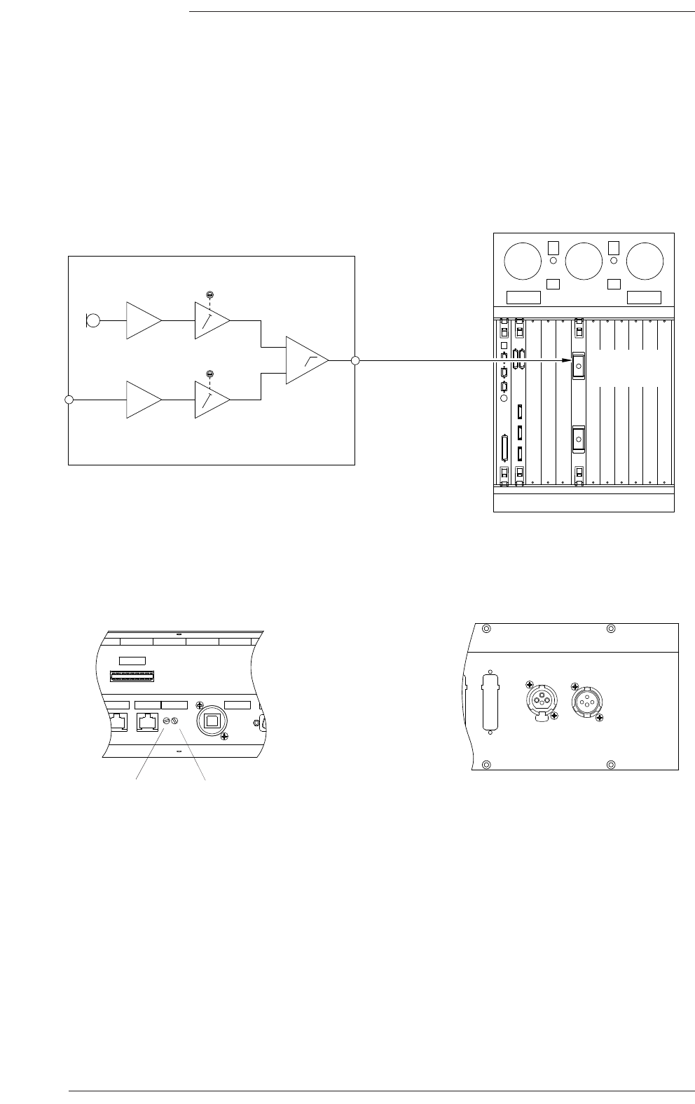
Page 40
C300HD Installation Guide
USB OUT
ETHER 3 ETHER 4 MIC/GN
CTRL 3
D8
EXT T/B
MIC IN
TALKBACK
OUTPUT
PUSH
∑
INT GAIN
EXT GAIN
Internal
Mic
External
Mic in
Analogue
I/O card
C300HD Console
Talkback Block Diagram
External Mic Input and Talkback Mix
Output connectors
Connector Panels
Talkback
Output
Centuri Chassis
External
mic gain
trim
Internal
mic gain
trim

Talkback and Oscillator
Talkback Connections
The C300HD console contains a built-in talkback microphone and amplifier. In addition, a second input is available for
connection to an external dynamic microphone. This input is mixed with the internal T/B mic and the combined signal is
available via an XLR connector on the audio interface panel beneath the console. This output signal should be connected
to an analogue input circuit in the Centuri processor. The circuit chosen can then be assigned as the talkback source via
the console’s routing.
The gain of each mic signal can be independently adjusted. Access to the trim controls is from beneath the console on the
console interface panel.
The external mic input is via a 3-pin XLR female labelled ‘Ext T/B Mic In’.
The mixed T/B output is via a 3-pin XLR Male labelled ‘Talkback Output’.
Oscillator Connections
The C300HD includes an inbuilt software oscillator capable of generating a range of sinusoidal frequencies as well as pink
noise. This signal can be assigned to any relevant output without additional cabling.
Alternatively, an external oscillator (either analogue or digital, mono or stereo) may be used. In this instance one or two
circuits should be allocated on an input card, they can then be assigned as the oscillator source.
Refer to Appendix C for connector pinouts.
Installation Wiring
Section 5
Page 41
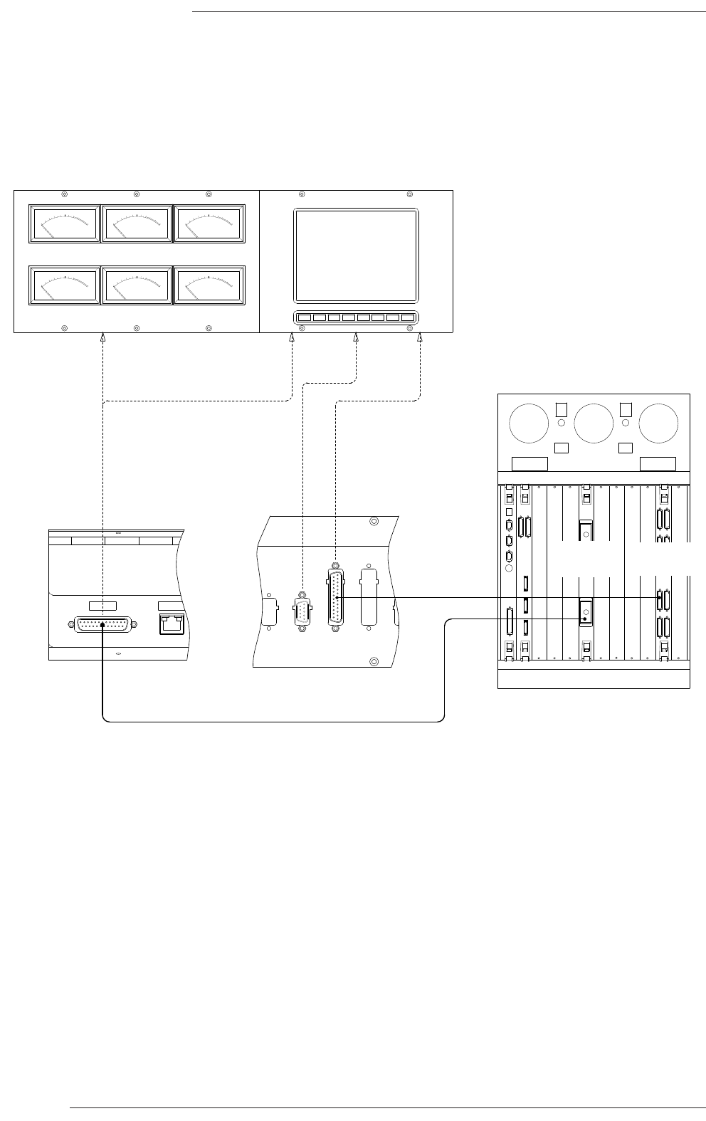
Page 42
C300HD Installation Guide
Meter and Phasescope Wiring
-2
-3
-5
-7
-10
-20
-1
0
+1
+2
+3
VU
VU
-2
-3
-5
-7
-10
-20
-1
0
+1
+2
+3
VU
VU
-2
-3
-5
-7
-10
-20
-1
0
+1
+2
+3
VU
VU
-2
-3
-5
-7
-10
-20
-1
0
+1
+2
+3
VU
VU
-2
-3
-5
-7
-10
-20
-1
0
+1
+2
+3
VU
VU
-2
-3
-5
-7
-10
-20
-1
0
+1
+2
+3
VU
VU
VU MTRS ETH CTRL
VIDEO
IN
MSD
DIAG
PHASE
SCOPE
REMOTE
POWER IN
Analogue
I/O card
Digital
I/O card
3 (or 4) off
AES/EBU ccts.
6 (or 8) off analogue ccts.

Installation Wiring
Section 5
Page 43
Meters and Phasescope
A Centre Section of the C300HD console can optionally be equipped with six off analogue VU meters with screening for
5.1 monitoring channels. In addition, each Centre Section may be fitted with an LCD phasescope. Two standard phasescope
types are available, the MSD600C or the RTW 10830. Other custom meter solutions may be possible. Note that if the
number of mechanical VU meters fitted is increased to eight, then there is no longer room for a phasescope.
Cable connections to the meters and phasescope will need to be run between the Centuri and the Console. Both balanced
analogue and 110Ω digital cables may be necessary depending on configuration. These cables are not supplied by SSL.
The MSD600C 5.1 phasescope has inputs for 6 digital signals (3 AES/EBU pairs), plus a serial diagnostic port.
The RTW 10830 has eight digital input signals, eight digital output signals, eight analogue input signals plus a remote control
port. Note that the analogue input signals would normally feed both the phasescope and the mechanical meters.
The signals for the Analogue meters could be paralleled from the console main output signals or, alternatively, independent
feeds from the analogue output card.
Refer to page 53 for the analogue meter wiring pinout and page 54 for the digital wiring.
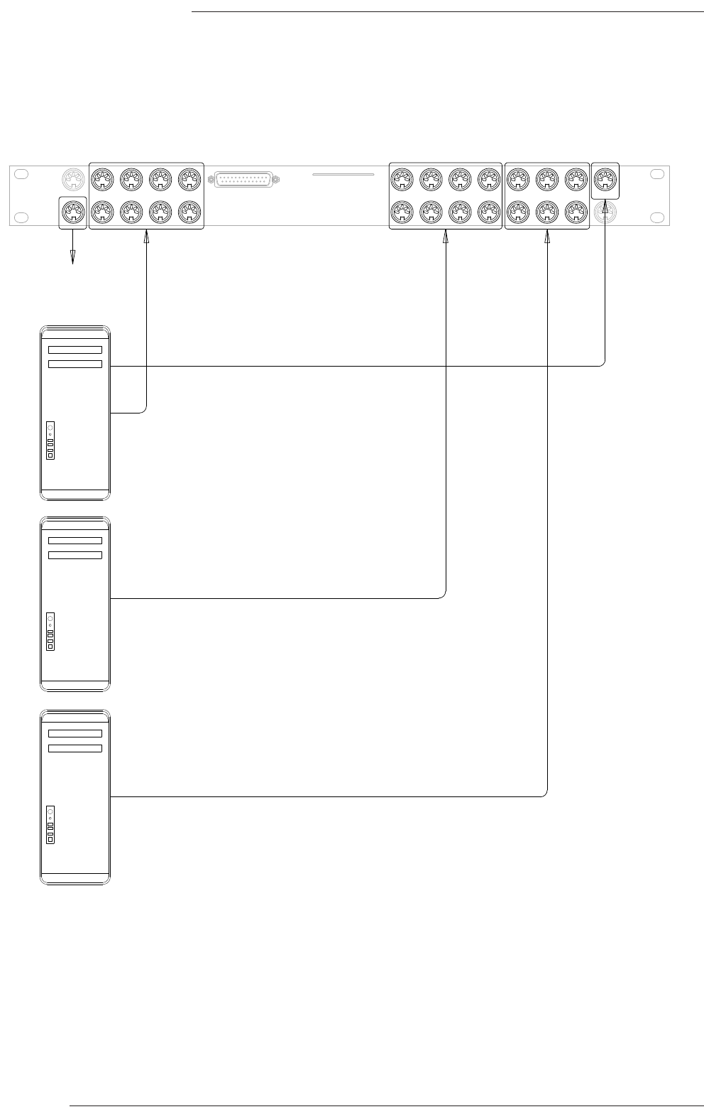
Page 44
C300HD Installation Guide
EXPANSION
TIME 1234 56789101112
MIDI IN
MIDI OUT
MIDI IN
MIDI OUT
CODE
DAW MIDI Interface Panel
Timecode
output MMC option
(input only)
Midi 9–11Midi 5–8Midi 1–4
Workstation 1
(Master)
Workstation 2
(Slave)
Workstation 3
(Slave)
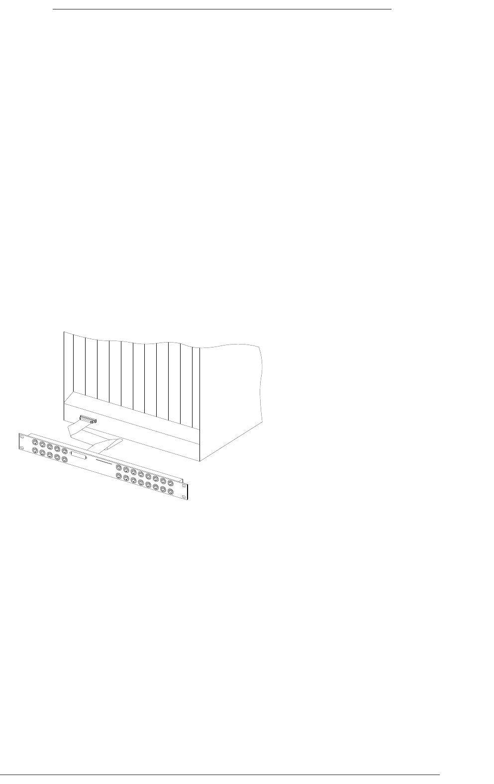
DAW MIDI Connection (Option)
The DAW interface is supplied as standard and a separate 1U breakout panel is provided for access to the system’s Midi
circuits. This panel is connected to the lower rear of the Centuri chassis and should be mounted in a suitable position in
the equipment rack. (See diagram below).
The panel provides access to 12 pairs of MIDI ports for workstation control using the ‘HUI’ protocol together with a MIDI
timecode output from the console’s internal timecode generator. The port marked ‘IN Timecode’ is currently not used.
Each pair of DAW ports supports 8 channels of workstation control. These ports can be distributed amongst four different
workstations. The maximum number of ports that can be utilised for control is workstation specific – for example, the
DigiDesign Pro Tools is limited to a maximum of 4 ports. Please consult the DAW documentation to determine how many
physical ports can be used. In most cases the DAW software supports banking so that the physical console control channels
can be paged through all the available tracks in a workstation session.
Port 12 ‘IN’ also accepts the MMC (Midi Machine Control) locate command. This is used in conjunction with timecode
from the master DAW to update the desk timeline.
Standard Midi 5-pin DIN cables should be used to connect the workstation.
The ‘Expansion’ connector has no function on C300.
Refer to Appendix G page 68 for additional information on machine control.
Installation Wiring
Section 5
Page 45
Midi breakout panel connection
at the rear of the Centuri chassis
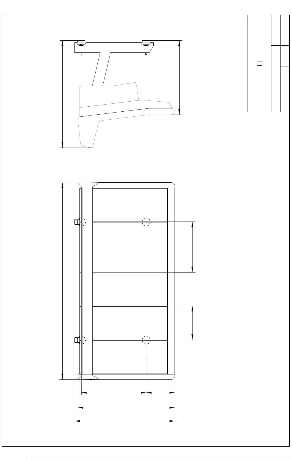
Page 46
C300HD Installation Guide
283 640
959
988
1 – 8 Centre Section9 – 16 17 – 24 25 – 32
1944
733
1059
334 498
Title:
Client:
Sheet: Revision:
Drawn by:
Date: 21/02/08
GC
Footprint C300 – 32 Channels
Standard Configuration
Proposal 0.1
Solid State Logic
S V I S I NOO U N D
32 channel footprint drawing.
Refer to table opposite when calculating frame configurations. Alternatively, contact
SSL Project Engineering at: projeng@solidstatelogic.com
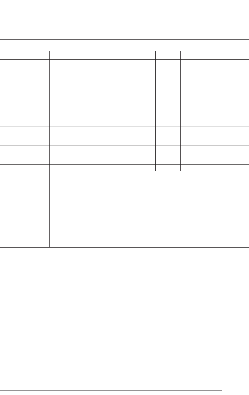
Appendix A – Specifications
Page 47
Appendix A: Specifications
C300HD Console
Parameter Condition Value Unit Notes
Height To top of meter trim 1056 U
Height adjustment -0 +45 mm
Width Centre Section plus end trims 608 mm
8 fader channel bay 334 mm
Producer’s table section
Additional Master Section
491 mm
498 mm
Depth 988 mm
Weight 24 channels with 2 legs 164 kg
8 fader bay (add/subtract) 35 kg
Additional leg 13 kg
Heat Dissipation 24 channels, single Master section 270 W approximately
8 fader bay (add/subtract) 70 W approximately
Voltage Range 100 – 240 V AC only ±10%
Current 48ch. Maximum over voltage range 10.3 – 4.3 A
Power Factor 0.95 approximately
Fusing No user-accessible fuses
Noise Fanless
Connectors Power in main/backup Harting™ Modular 3-pin
Network RJ45 100 baseT
Control Surface 3M™ MDR high-density 50-way female
Video in 1 and 2 HD15 female
Trackball out USB B female
External USB in USB A female
Phasescope input – digital 25-way D-type female (where specified)
Phasescope diagnostics/control 9-way D-type female (where specified)
Meter inputs – analogue 25-way D-type male (where specified)
Osc/Status Lock 25-way D-type female
External T/B mic input XLR 3-way female
T/B audio output XLR 3-way male
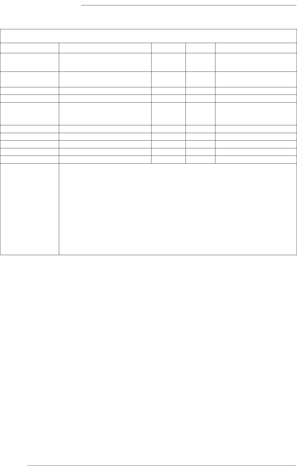
Page 48
C300HD Installation Guide
Centuri Processor Crate
Parameter Condition Value Unit Notes
Height 15 U
665 mm
Width 19in
Case only without rack ears 449 mm
Depth 592 mmexcludes connectors/cables
Weight (†) 35 – 45 kg depending on I/O fitted
Heat Dissipation 32 DSP, no I/O 300 W minimum
64 DSP, 24 mics, 48 analogue 550 W typical
128 DSP, 48 mics, 96 analogue 910 W maximum
Voltage Range 100 – 240 V AC only
Current Maximum over voltage range 12.3 – 4.9 A
Power Factor 0.95 approximately
Fusing Thermal current trip. No fuses 16 A each input
Noise 75 dB(A) approximately
Connectors Power in 1 and 2 IEC male
Network RJ45 100 baseT
Sync in BNC 75Ω analogue video
Video out 1, 2 and 3 HD15 female
Serial 62-way HD D-type female 9-way breakout lead supplied
Control Surface 3M™ MDR high-density 50-way female
Machine Control 25-way D-type male
Timecode 25-way D-type female
Control Power Indicators 25-way D-type female
Remote Power Indicators 9-way D-type male unused
Expansion 25-way D-type female unused
MIDI 5-pin 180° DIN female
† Centuri must be supported on rack shelves. Do not rely on the rack ears alone.
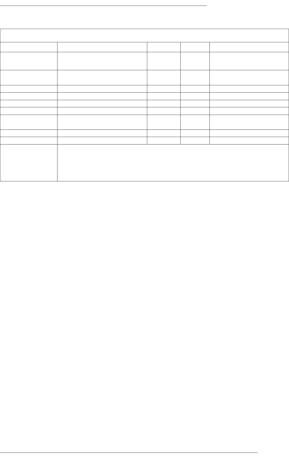
Appendix A – Specifications
Page 49
Netbridge
Parameter Condition Value Unit Notes
Height 2 U
89 mm
Width 19in
Case only without rack ears 432 mm
Depth 360 mmexcludes connectors/cables
Weight (†) 11 kg
Heat Dissipation 32 DSP, no I/O 45 W maximum
Voltage Switch selectable 115 or 230 V AC only
Current At 115V input 0.5 A
At 230V input 0.2 A
Fusing No external fuses
Noise 50 dB(A) approximately
Connectors Power in IEC male
Network – TCP/IP RJ45
Network – SSL RJ45
Terminal 9-way D-type male
Serial 62-way HD D-type female 9-way breakout lead supplied
† Netbridge must be supported on rack shelves. Do not rely on the rack ears alone.
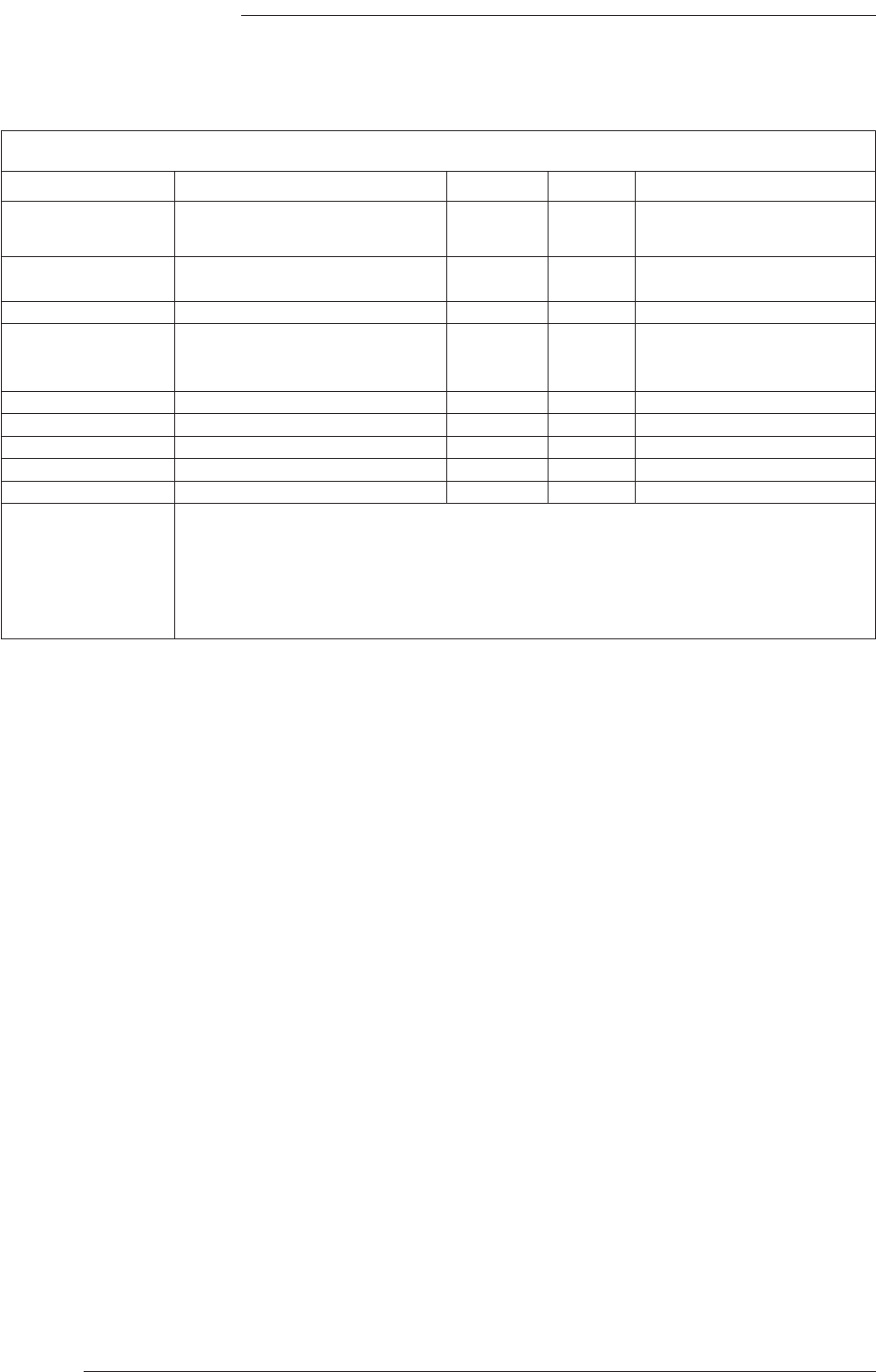
Page 50
C300HD Installation Guide
(†) Cooling is via vents at the top and bottom of the front panel. Do not obstruct these vents – refer to Appendix F
for additional information.
C-SB Stagebox
Parameter Condition Value Unit Notes
Height 14 U
620 mm
Width 19 in
Case only without rack ears 432 mm
Depth 462 mm excludes connectors/cables
Weight Rack with single PSU unit 19 kg
Each Mic input or Line output card 1.7 kg
Additional PSU module 5.8 kg
Heat Dissipation (†) 380 W maximum with 48ch fitted
Voltage Range 100 – 240 V AC only
Current At voltage range 10.0 – 3.9 A maximum with 48ch fitted
Fusing 6.3(T) A 1.25” time delay
Noise Fanless
Connectors Mains supply in IEC male
Mains supply output (x2) IEC female 6A max total
Network – SSL RJ45
Microphone input XLR 3-pin female pin 2 hot
Insert send 25-pin D-type male
Audio interface (FibreLink) Duplex SC fibre optic
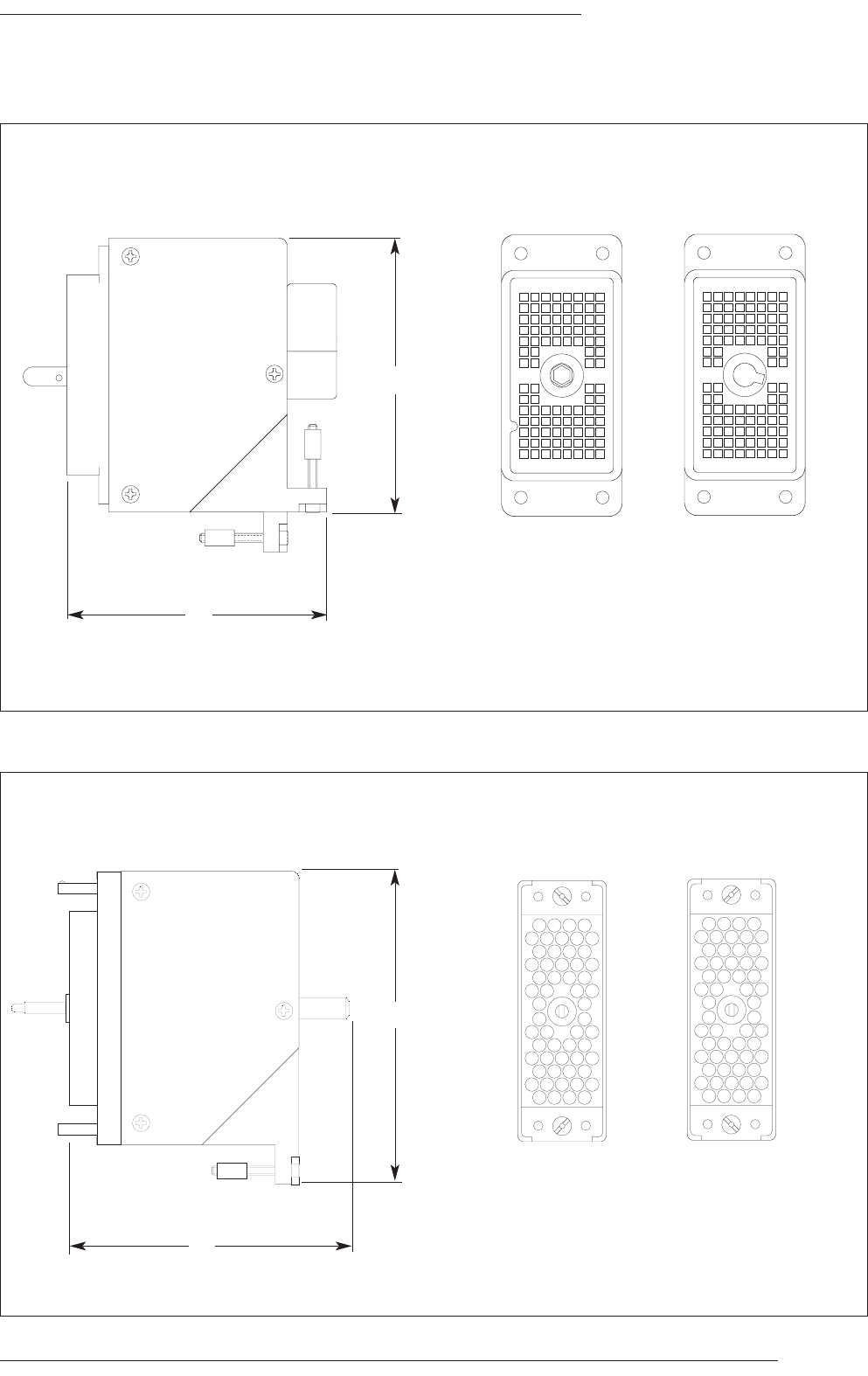
Appendix B – Connector Details
Page 51
Appendix B: Connector Details
HHoooodd
HHoooodd
PPlluugg
FFrreeee SSoocckkeettFFrreeee PPlluugg
Connectors Viewed From Wiring Side
Connectors Viewed From Wiring Side
A
B
C
D
E
F
G
H
J
K
L
M
N
P
1
2
3
4
5
6
7
8
1
2
3
4
5
6
7
8
SSoocckkeett
D
DL
L
9
96
6-
-P
Pi
in
n
VVaarriiccoonn™™ 5566--ppiinn
Dimensions: 29mm x 69mm
Dimensions: 22mm x 67mm
A
E
R
a
k
u
DD
L
W
e
h
p
z
KK
B
F
S
b
l
v
EE
M
X
r
AA
LL
C
H
T
w
FF
N
Y
s
BB
MM
D
J
U
c
m
x
HH
P
Z
f
j
t
CC
NN
K
V
d
n
y
JJ
A
E
R
a
k
u
DD
L
W
e
h
p
z
KK
B
F
S
b
l
v
EE
M
X
r
AA
LL
C
H
T
w
FF
N
Y
s
BB
MM
D
J
U
c
m
x
HH
P
Z
f
j
t
CC
NN
K
V
d
n
y
JJ
70
68
79
69
1
2
3
4
5
6
7
8
A
B
C
D
E
F
G
H
J
K
L
M
N
P
1
2
3
4
5
6
7
8
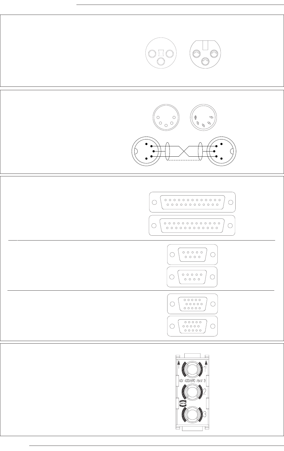
C300HD Installation Guide
Page 52
Connectors Viewed From Wiring Side
1
2
3
4
5
14
15
16
17
6
7
8
9
10
18
19
20
21
11
12
13
22
23
24
25
1
2
3
4
5
14
15
16
17
6
7
8
9
10
18
19
20
21
11
12
13
22
23
24
25
1
2
3
4
5
6
7
8
9
1
5
15
6
10
11
1
2
3
4
5
6
7
8
9
D-Type Multipin
Harting Mains Insert
2255--wwaayy
Dimensions: 55 x 15mm (approx.)
Cable Dia: 8mm (typical)
99--wwaayy
Dimensions: 35 x 15mm (approx.)
Cable Dia: 7mm (typical)
HHDD 1155--wwaayy
Dimensions: 35 x 15mm (approx.)
Cable Dia: 12mm
RGBHV (XGA) connector
Plug
Socket
Plug
Socket
Plug
Socket
1
5
15
6
10
11
Socket
Viewed from
wiring side
Pin 1 LIVE
Pin 2 n/c
Pin 3 NEUTRAL
Earth contact is via Earth pin in the housing frame
Note: The inserts utilise crimped pins which are not removable.
Part SSL Part Number
3-way socket housing 32VAK3DC
40A Contact 32VAQXEX
Plug Socket
12
3
1
2
3
XLR 3-Pin
Dimensions: 19 x 60mm (approx.)
Cable Dia: 8-12mm (typical)
Pinout for balanced audio:
Pin 1 - Screen/Ground
Pin 2 - Hot (+ve)
Pin 3 - Cold (-ve)
Connectors Viewed
From Wiring Side
Connectors Viewed
From Wiring Side
Midi lead
construction
Plug Socket
1
2
3
4
5
1
2
3
4
5
DIN 5-Pin 180°
Dimensions: 15mm dia.
Cable Dia: 4mm - 7mm (typical)
Pinout for MIDI signals:
Pin 1 - n/c
Pin 2 - Screen
Pin 3 - n/c
Pin 4 - Midi +
Pin 5 - Midi -
1
3
2
4
51
3
2
4
5
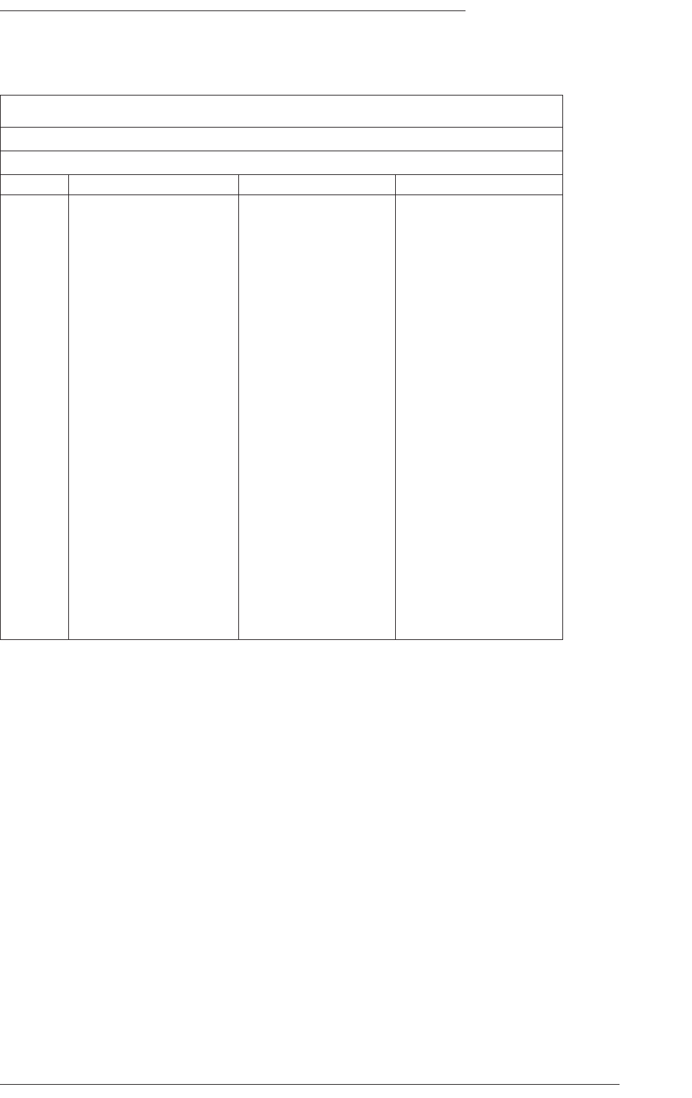
Appendix C – Connector Pinouts
Page 53
Appendix C: Connector Pinouts – C300HD Console
Note. Connector only fitted if VU meter panel or RTW phasescope specified.
Meter Inputs (Analogue Circuits)
Location: Console Connector Panel
Connector Type: 25-way D-type male
pin Description Notes: VU or PPM Notes: RTW10830
1 Meter 1 input + Left meter Input 1
14 Meter 1 input -
2 n/c
15 Meter 2 input + Centre meter Input 2
3 Meter 2 input -
16 n/c
4 Meter 3 input + Right meter Input 3
17 Meter 3 input -
5 n/c
18 Meter 4 input + LS meter Input 4
6 Meter 4 input -
19 n/c
7 Meter 5 input + SW meter Input 5
20 Meter 5 input -
8 n/c
21 Meter 6 input + RS meter Input 6
9 Meter 6 input -
22 n/c
10 Meter 7 input + unused Input 7
23 Meter 7 input -
11 n/c
24 Meter 8 input + unused Input 8
12 Meter 8 input -
25 n/c
13 n/c
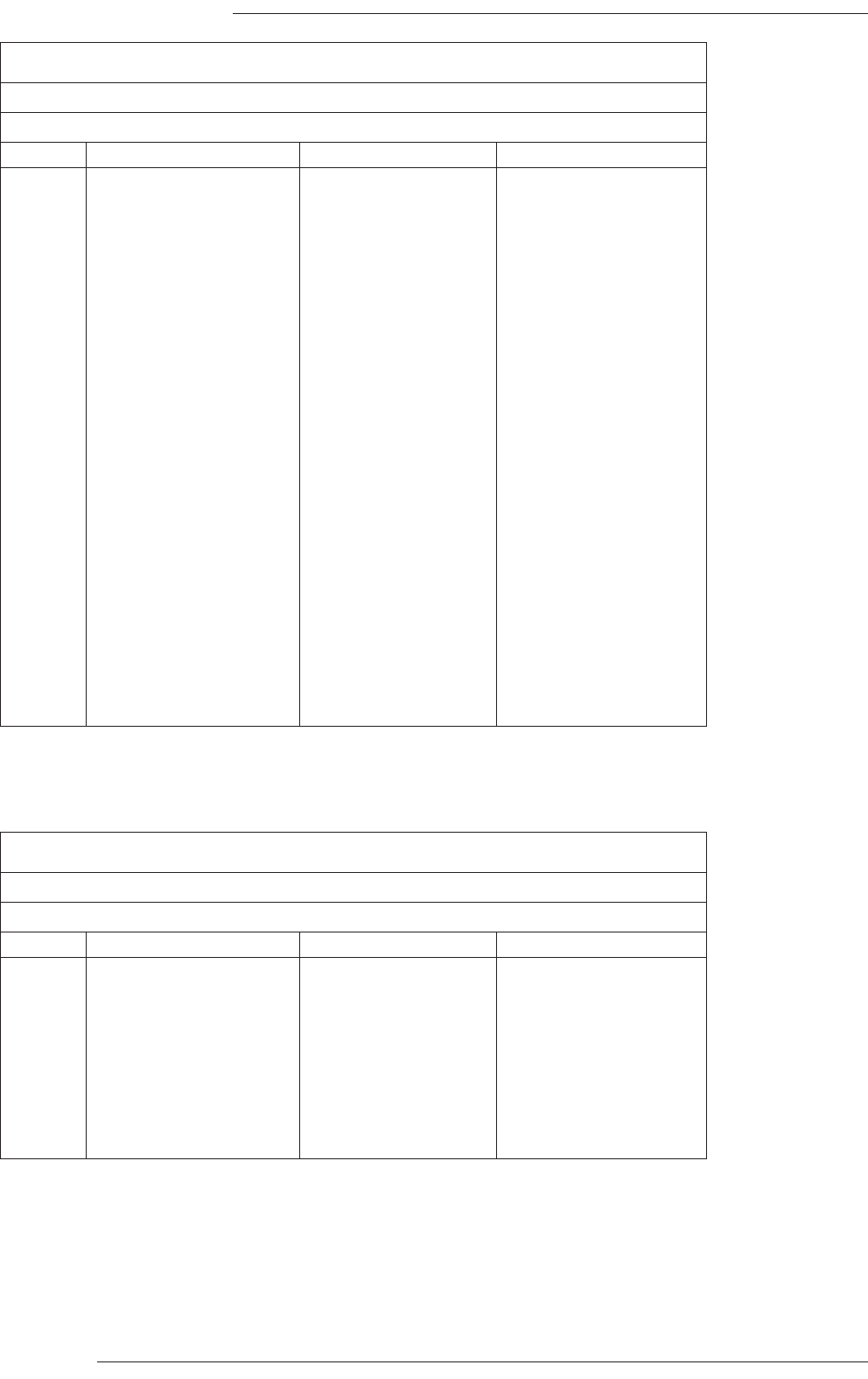
C300HD Installation Guide
Page 54
Phase Scope (Digital Circuits)
Location: Audio connector panel
Connector Type: 25-way D-type female
pin Description Notes: MSD600 Notes: RTW10830
1 Circuit 1 + AES/EBU in 1/2 AES/EBU out 7/8*
14 Circuit 1 -
2 n/c
15 Circuit 2 + AES/EBU in 3/4 AES/EBU out 5/6*
3 Circuit 2 -
16 n/c
4 Circuit 3 + AES/EBU in 5/6 AES/EBU out 3/4*
17 Circuit 3 -
5 n/c
18 Circuit 4 + unused AES/EBU out 1/2*
6 Circuit 4 -
19 n/c
7 Circuit 5 + unused AES/EBU in 7/8
20 Circuit 5 -
8 n/c
21 Circuit 6 + unused AES/EBU in 5/6
9 Circuit 6 -
22 n/c
10 Circuit 7 + unused AES/EBU in 3/4
23 Circuit 7 -
11 n/c
24 Circuit 8 + unused AES/EBU in 1/2
12 Circuit 8 -
25 n/c
13 n/c
Phase Scope (Diagnostics and Control)
Location: Audio connector panel
Connector Type: 9-way D-type female
pin Notes: MSD600 Notes: RTW10830
1 Chassis Switch common
6 n/c Mode
2 Rx Data Select
7 n/c Memo
3 Tx Data Gain
8 n/c Reset
4 n/c Shift
9 n/c n/c
5 n/c n/c
* Output circuits are looped through from the corresponding input within the RTW meter.
Note. Connectors only fitted if a phasescope is specified.
Refer to manufacturer’s own manual for diagnostic information and operating instructions.
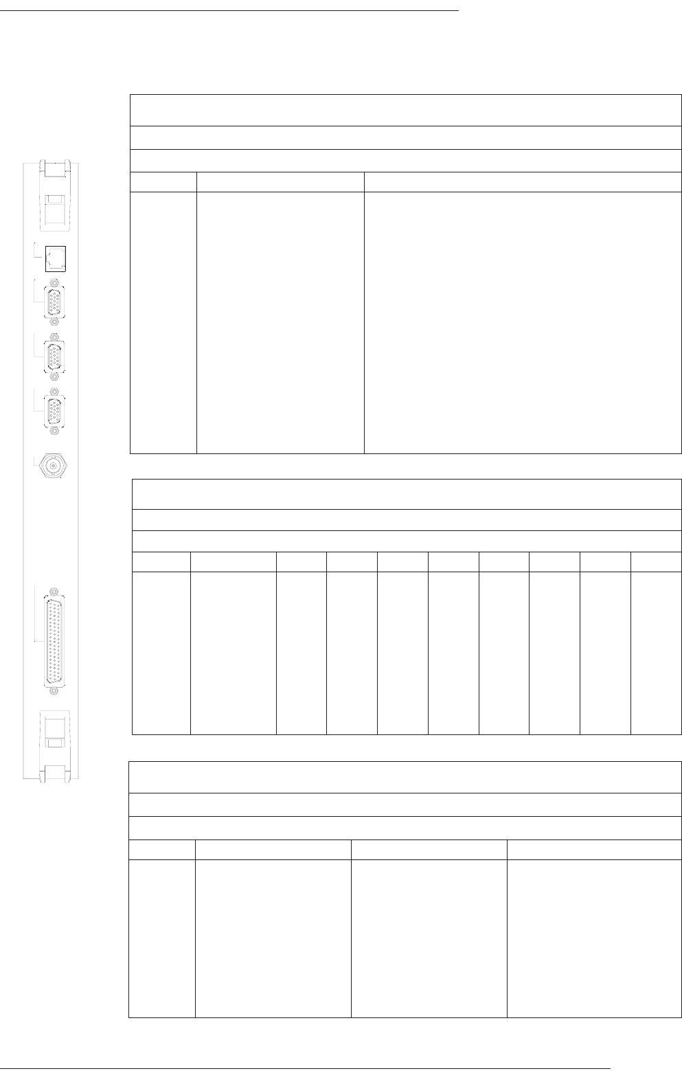
Appendix C – Connector Pinouts
Page 55
Connector Pinouts – Centuri Processor
Video
Location: Centuri – CPU Card
Connector Type: HD15 female
pin Description Notes:
1 Red
2 Green
3 Blue
4 ID bit
5 n/c
6 Red screen
7 Green screen
8 Blue screen
9 n/c
10 Ground
11 ID bit
12 ID bit
13 H sync
14 V sync
15 n/c
ETHERNET
VIDEO 3
VIDEO 2
SYNC
VIDEO 1
960XA
SERIAL
Serial (62pin to 8 off 9-pin breakout lead)
Location: Centuri – CPU card
Connector Type: 62-way high-density D-type female
D9-pin Description TTY-A TTY-B TTY-C TTY-D TTY-E TTY-F TTY-G TTY-H
1 0V 7 28 14 52 21 42 35 59
6 0V 5 26 12 50 19 40 33 57
2 Rx Data L 2 23 9 47 16 37 30 54
7 Rx Data H 3 24 10 48 17 38 31 55
3 Tx Data H 2 22 8 46 15 36 29 53
8 Tx Data L 4 25 11 49 18 39 32 56
4 0V 6 27 13 51 20 41 34 58
9 n/c - - - - - - - -
5 0V 43 45 44 44 62 61 60 61
TTY A –H
Location: Centuri CPU serial breakout adapter lead
Connector Type: 9-way D-type male (8 off)
pin Con. A–E, F–H (RS422) Con. E (RS232) Notes:
1 0V 0V
6 0V 0V
2 Rx Data L Tx Data
7 Rx Data H 0V
3 Tx Data H Rx Data
8 Tx Data L n/c
4 0V n/c
9 n/c n/c
5 0V 0V
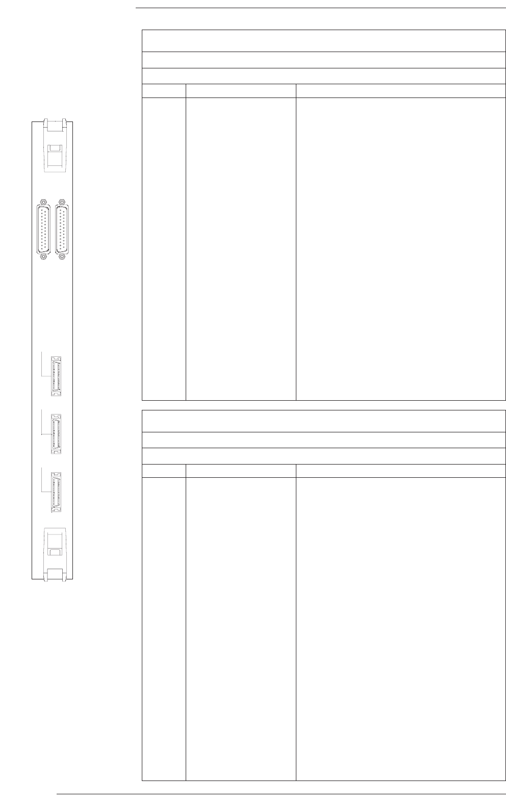
C300HD Installation Guide
Page 56
Timecode
Location: Centuri – Console interface card
Connector Type: 25-way D-type male
pin Description Notes:
1 in 1 +
14 in 1 -
2 in 1 gnd
15 in 2 +
3 in 2 -
16 in 2 gnd
4 in 3 +
17 in 3 -
5 in 3 gnd
18 in 4 +
6 in 4 -
19 in 4 gnd
7 unused
20 out 1 +
8 out 1 -
21 out 1 gnd
9 out 2 +
22 out 2 -
10 out 2 gnd
23 out 3 +
11 out 3 -
24 out 3 gnd
12 out 4 +
25 out 4 -
13 out 4 gnd
Machine Control
Location: Centuri – Console interface card
Connector Type: 25-way D-type female
pin Description Notes:
1 n/c
14 n/c
2 Tally common Tally voltage can be AC or DC 4V to 30V.
15 Switch common
3 Rewind switch
16 Rewind tally
4 Forward switch
17 Forward tally
5 Stop switch
18 Stop tally
6 Play switch
19 Play tally
7 Skip back switch
20 Skip back tally
8 Record switch
21 Record tally
9 Tach 1
22 Tach 2
10 Dir 1
23 Dir 2
11 n/c
24 n/c
12 n/c
25 n/c
13 n/c
MACHINE
CONTROL
TIME
CODE
CONTROL
SURFACE 1
CONTROL
SURFACE 2
CONTROL
SURFACE 3
906XA
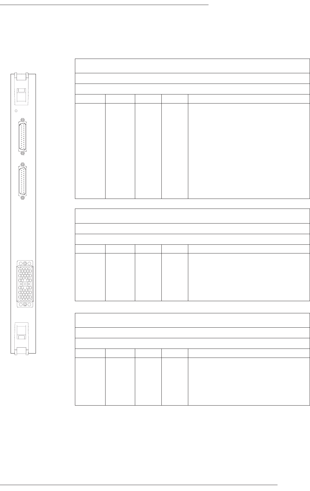
Appendix C – Connector Pinouts
Page 57
Mic Input Card (‘908)
+5V
1-6
7-12
SPLIT OUTPUTS
MIC IN
1 - 12
908XA
A
Split Outputs 1 –6
Location: 908 Micamp
Connector Type: 25-way D-type female
Cct Hot Cold Screen Notes
1 24 12 25 Pin 13 unused
2 10 23 11
3 21 9 22
4 7 20 8
5 18 6 19
6 4 17 5
Split Outputs 7 – 12
Location: 908 Micamp
Connector Type: 25-way D-type female
Cct Hot Cold Screen Notes
7 24 12 25 Pin 13 unused
8 10 23 11
9 21 9 22
10 7 20 8
11 18 6 19
12 4 17 5
MIC In 1 – 12
Location: 908 Micamp
Connector Type: Varicon 56-way female
Cct Hot Cold Screen Notes
1 D K P All other pins unused
2 C J N
3 A E L
4 B F M
5 V Z d
6 U Y c
7 R W a
8 S X b
9 n t y
10 m s x
11 k p u
12 l r v
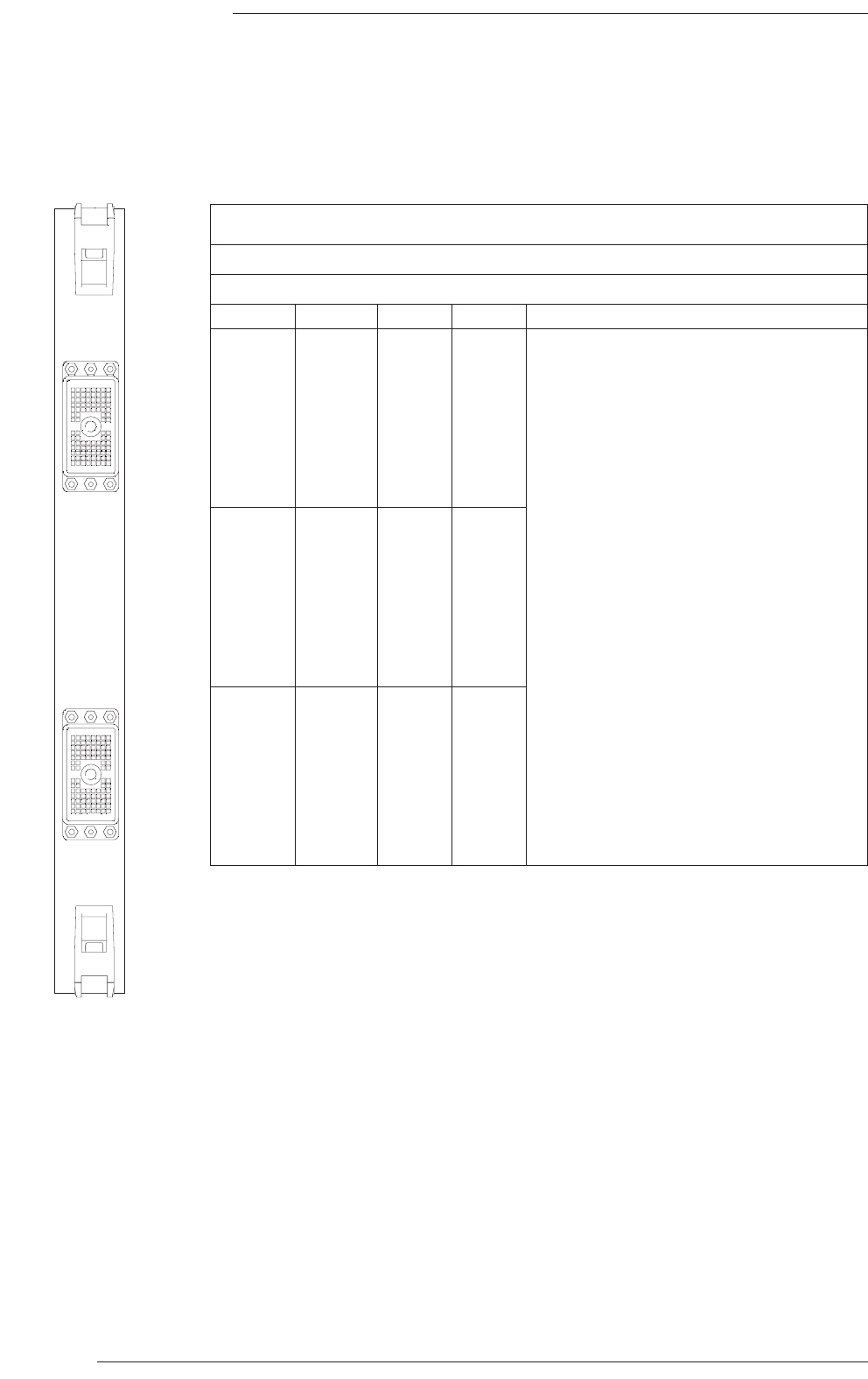
Analogue In / Out
Location: 904 Analogue Card
Connector Type: DL96 female
Cct Hot Cold Screen Notes
1 A1 B1 C1 all other pins unused
2 A2 B2 C2
3 A3 B3 C3
4 A4 B4 C4
5 A5 B5 C5
6 A6 B6 C6
7 A7 B7 C7
8 A8 B8 C8
9 D1 E1 F1
10 D2 E2 F2
11 D3 E3 G1
12 D4 E4 G2
13 D5 E5 G7
14 D6 E6 G8
15 D7 E7 F7
16 D8 E8 F8
17 L1 K1 J1
18 L2 K2 J2
19 L3 K3 H1
20 L4 K4 H2
21 L5 K5 H7
22 L6 K6 H8
23 L7 K7 J7
24 L8 K8 J8
C300HD Installation Guide
Page 58
Analogue I/O Card (‘904)
A1
A1
ANALOGUE IN
1 - 24
ANALOGUE OUT
1 - 24
904XA
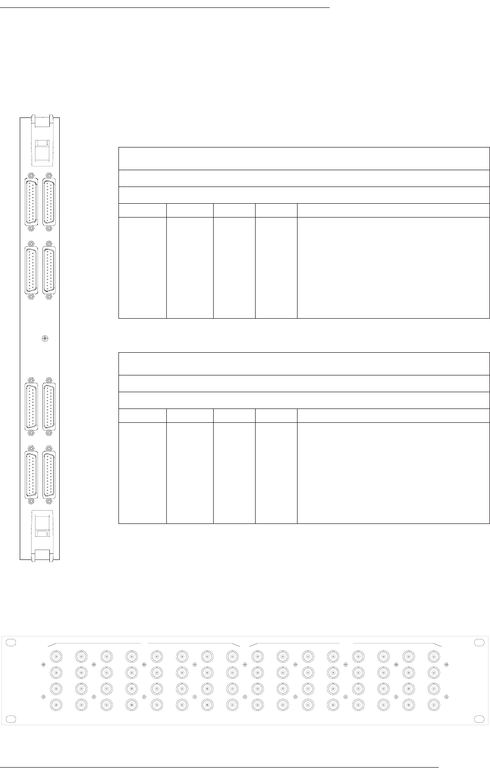
Appendix C – Connector Pinouts
Page 59
9 - 16
1 - 8
25 - 32
17 - 24
AES/EBU IN
9 - 16
1 - 8
25 - 32
17 - 24
902XB
AES/EBU OUT
Digital I/O Card (‘902)
BNC Breakout Panel
1291
0
1
7
1
8
2
5
2
6
341
1
1
2
1
9
2
0
2
7
2
8
5 6131
4
2
1
2
2
2
9
3
0
781
5
1
6
2
3
2
4
3
1
3
2
1291
0
1
7
1
8
2
5
2
6
341
1
1
2
1
9
2
0
2
7
2
8
5 6131
4
2
1
2
2
2
9
3
0
781
5
1
6
2
3
2
4
3
1
3
2
IN OUT
AES/EBU In 1–8 (9–16, 17–24, 25–32)
Location: 902 DIO
Connector Type: 25-way D-type female
Cct Hot Cold Screen Notes
124 12 25 Pin 13 unused
210 23 11
321 9 22
47 20 8
518 6 19
64 17 5
715 3 16
8 1 14 2
AES/EBU Out 1–8 (9–16, 17–24, 25–32)
Location: 902 DIO
Connector Type: 25-way D-type female
Cct Hot Cold Screen Notes
1 24 12 25 Pin 13 unused
2 10 23 11
3 21 9 22
4 7 20 8
5 18 6 19
6 4 17 5
7 15 3 16
8114 2
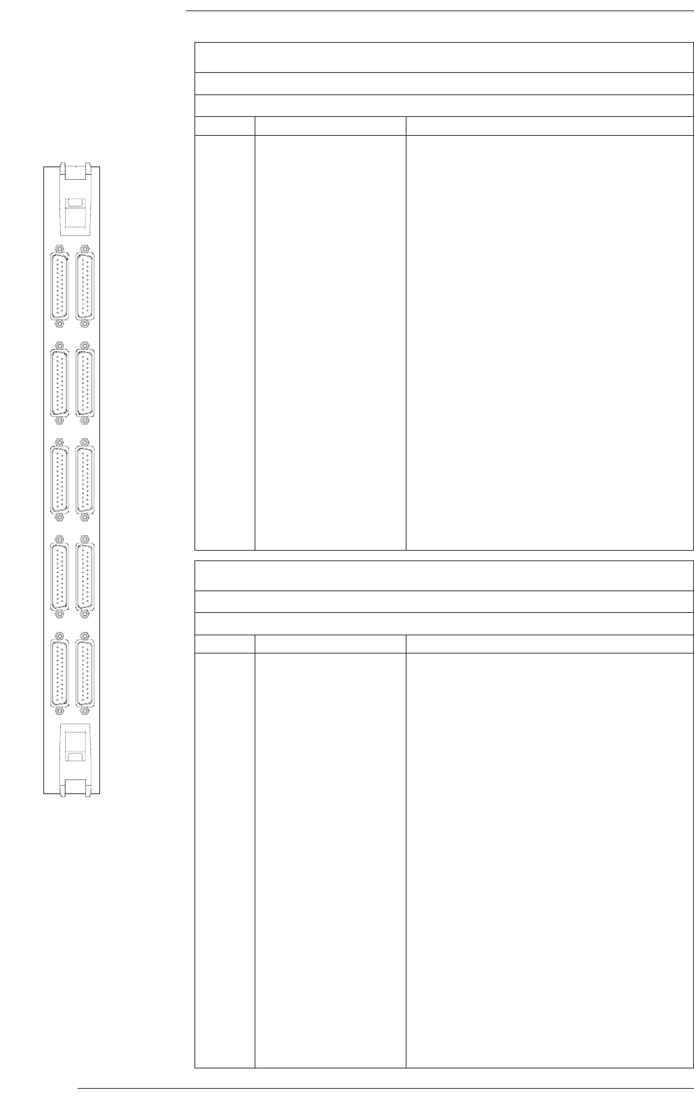
GPI Outputs 1–12 (13–24, 25–36, 37–48, 49–60)
Location: Centuri – Relay card
Connector Type: 25-way D-type female
pin Description Notes:
1 Output 1A
14 Output 1B
2 Output 2A
15 Output 2B
3 Output 3A
16 Output 3B
4 Output 4A
17 Output 4B
5 Output 5A
18 Output 5B
6 Output 6A
19 Output 6B
7 Output 7A
20 Output 7B
8 Output 8A
21 Output 8B
9 Output 9A
22 Output 9B
10 Output 10A
23 Output 10B
11 Output 11A
24 Output 11B
12 Output 12A
25 Output 12B
13 +15V 450mA across all connectors
C300HD Installation Guide
Page 60
GPI I/O Card (‘907)
IN
OUT
1 - 12
13 - 24
25 - 36
37 - 48
49 - 60
1 - 12
13 - 24
25 - 36
37 - 48
49 - 60
GPI
907XA
GPI Inputs 1–12 (13–24, 25–36, 37–48, 49–60)
Location: Centuri – Relay card
Connector Type: 25-way D-type male
pin Description Notes:
1 Input 1A
14 Input 1B
2 Input 2A
15 Input 2B
3 Input 3A
16Input 3B
4 Input 4A
17 Input 4B
5 Input 5A
18 Input 5B
6 Input 6A
19 Input 6B
7 Input 7A
20 Input 7B
8 Input 8A
21 Input 8B
9 Input 9A
22 Input 9B
10 Input 10A
23 Input 10B
11 Input 11A
24 Input 11B
12 Input 12A
25 Input 12B
13 0V
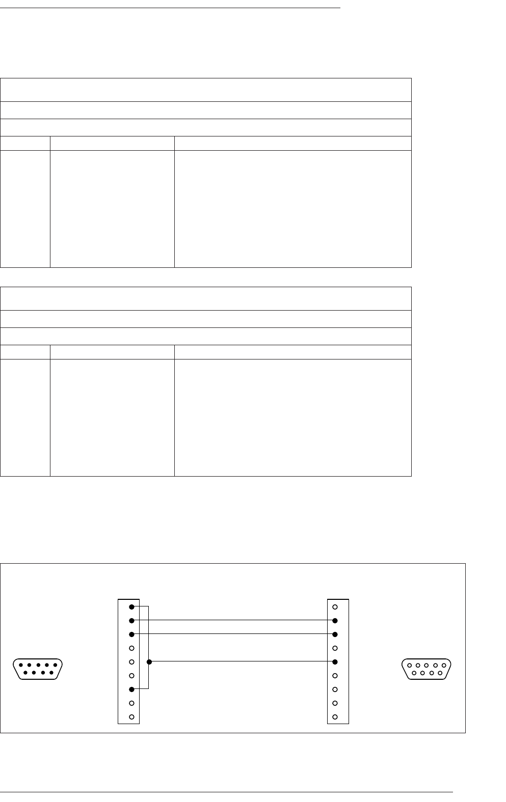
Appendix C – Connector Pinouts
Page 61
Connector Pinouts – NetBridge
Screen
Chassis
Tx Data
Gnd
Rx Data
n/c
n/c
n/c
9-way
Female
D-type
n/c
n/c
n/c
Rx Data
n/c
Tx Data
n/c
n/c
Gnd
n/c
n/c
9-way
Male
D-type
View from
solder side
View from
solder side
1
2
7
3
6
4
5
8
9
1
2
7
3
6
4
5
8
9
NetBridge
'Serial 1 - 7'
CPU Card
'Console'
15
69
51
96
NetBridge Diagnostic Cable
Serial 1–8 (RS232)
Location: Netbridge – Rear panel
Connector Type: 9-way D-type male
pin Description Notes:
1 Chassis
6 n/c
2 Rx Data
7 n/c
3 Tx Data
8 n/c
4 n/c
9 n/c
5 0V
Terminal (RS232)
Location: Netbridge – Rear panel
Connector Type: 9-way D-type male
pin Description Notes:
1 DCD Data Carrier Detect
6 DSR Data Set Ready
2 Rx Data
7 RTS Request To Send
3 Tx Data
8 CTS Clear To Send
4 DTR Data Terminal Ready
9 RI Ring Indicator
5 Signal ground

C300HD Installation Guide
Page 62
Resistor Colour Code:
Black 0
Brown 1
Red 2
Orange 3
Yellow 4
Green 5
Blue 6
Violet 7
Grey 8
White 9
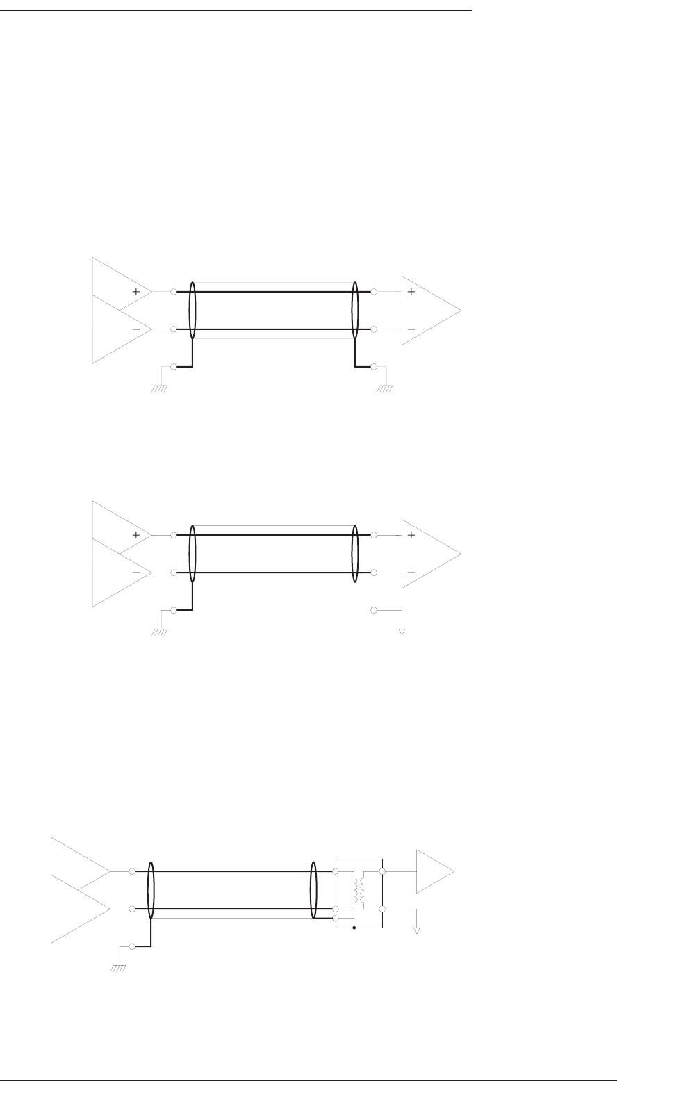
Appendix D – Audio Interfacing
Page 63
Appendix D: Audio Interfacing
All analogue audio inputs and outputs are electronically balanced. The screen pins are all directly connected to the chassis
at the point of entry to comply with AES/EBU grounding and EMC recommendations.
Balanced Circuits
It is strongly recommended that balanced connections are used wherever possible using high quality screened cable. The
following diagram shows the recommended connection with both screens connected to the chassis:
On some older items of equipment the screen connection may still be referenced to the circuit 0V rather than the chassis.
In these cases it may be advantageous to disconnect the screen at this connection. Note however that this practice will
degrade the EMC performance.
Connecting to Unbalanced Equipment
Connecting to unbalanced equipment can be much more problematic. It is much more likely that earth and induced RF
currents will become referenced to the audio 0V which will give rise to audible hum and buzz.
The recommendation for connection of balanced to unbalanced equipment is to isolate unbalanced connections by using
a balancing transformer.
chassis chassis
chassis 0V
chassis
0V
Balanced – Balanced
both screens connected to chassis
(recommended)
Balanced – Balanced
one screen connected to chassis
Balanced – Unbalanced
one screen connected to chassis
(recommended)

C300HD Installation Guide
Page 64
1 inch = 25.4mm (exactly)
1m = 3’ 3” (roughly)
1 mile = 1,600m (roughly)
1Kg = 2.2 Pounds (roughly)

Appendix E – Environmental Specifications
Page 65
Temperature Operating: 5 to 30 Deg. C
Non-operating: -20 to 50 Deg. C
Max. Gradient: 15 Deg. C/Hour
Relative Humidity Operating: 20 to 80 %
Non-operating: 5 to 90 %
Max. wet bulb: 29 Deg. C (non-condensing)
Vibration Operating: < 0.2 G (3 - 100Hz.)
Non-operating, power off: < 0.4 G (3 - 100Hz.)
Shock Operating: < 2 G (10mSec. Max.)
Non-operating: < 10 G (10mSec. Max.)
Altitude Operating: 0 to 3000 m
(above sea level) Non-operating: 0 to 12000 m
Appendix E: Environmental Specification

C300HD Installation Guide
Page 66
+4dBu = 1.229V rms.
0dBu = 0.775V rms.
-6dBu = 0.388V rms.

Appendix F – Stagebox Installation
Page 67
Appendix F: Additional Information for Installing Stageboxes
When positioning and installing a C-SB the following rules must be followed:
• Unobstructed airflow at front and rear.
• No obstruction to airflow, horizontally or vertically, within 300mm in front, above and below both the front and rear
panels.
• Ambient temperature no more than 30˚C measured at the air intake (lower front opening) or just below the rear
heatsink.
• Microphone cables must not obstruct the air intake. To help ensure this, a cable guide is provided down the sides of
the rack.
Design Requirements for a Flightcase
If a Stagebox is to be installed into a flight case the following requirements, in addition to those above, must be met to
ensure adequate passive cooling – otherwise user must install a ‘forced-ventilation kit’ option.
• Both front and rear covers must be completely removed during operation.
• The front and rear covers must be deep enough to ensure that the front and rear faces of Stagebox are flush with
front and rear of the open flight case.

C300HD Installation Guide
Page 68
Appendix G: C300HD Machine Control
Overview
C300HD features a comprehensive multi-port serial machine controller, a timecode reader and a virtual machine timecode
generator locked to the system master timeline, running synchronously at the system reference frequency. Both the
timecode reader and generator support ‘stationary’ timecode.
Two primary modes of operation are supported – multi machine synchronous control where each connected machine
resolves to a common sync reference at play speed, and asynchronous single machine control where the controlled
machine uses a local/internal reference for speed control with linear play speed timecode as the positional reference for
the ‘desk’ timeline.
Machines can be addressed using serial (RS422) control, direct HUI (MIDI) control, or legacy style parallel control with a
maximum of four devices online at any one time for synchronous operation, or a single device for asynchronous operation.
The Centuri core features a timecode reader with four switchable inputs, and LTC and MTC timecode generators, which
are locked to the designated ‘desk’ master position in all synchronous operating modes.
Asynchronous operation is supported in a timecode only chase system or via the DCTM (Direct Control of Tape Machine)
port, and requires continuous LTC from the master device at play speed.
The primary interface for control of external machines is the set of transport control buttons on the Automation and
Motion Control panel that allow any online machine (and the desk) to be put into play, record, fast-forward, rewind, etc. A
rotary encoder ‘wheel’, located next to the transport controls, can send true jog and shuttle commands to 9-pin controlled
devices, or can control the desk’s built in ‘virtual machine’ in comparable modes.
Primary Machine Control Options
Sony 9-Pin
controls machines using the Sony ‘P2’ RS422 remote protocol, including track arming support. This can be used with video
machines, DAT and MDM recorders which support 9-pin control, as well as disk-based workstations and recorders such
as Pro Tools, Nuendo, Radar, Sadie, Pyramix and Fairlight, which all have 9-pin emulation. Up to four machines may be
synchronised simultaneously using Sony 9-pin with either a nominated serial machine or the ‘desk’ as the system master.
On Slave devices selecting ‘LTC Chase ON’ from the port set up menu enables the controlled device’s internal timecode
synchroniser in Play and defeats slewing the device into lock via serial ‘Varispeed’ commands. This is normally the
recommended approach to controlling DAWs as slaves whilst retaining control of Track arming and Master Record from
the C300HD front panel.
It is mandatory that all controlled serial machines are set up for ‘Ext Video Sync’ operation using a video reference from
a suitable house sync generator and with the ‘SYNC PLAY’ option enabled if applicable (which is the case for the majority
of machines except VTRs). This rule is particularly important for digital audio recorders.
Indirect control of machines may also be achieved via third-party machine control systems such as units from Soundmaster,
CB Electronics and Tamura; all have a control port, which emulates a single 9-pin machine.
LTC Slave
The desk follows play speed timecode from a locally controlled machine. Supports the MMC (Midi Machine Control) locate
commands to follow positional changes from machines, primarily DAWs, which only output play speed timecode. MIDI Port
12 must be used to receive MMC locates.

Appendix G – Machine Control
Page 69
Additional Machine Control options
Sony/LTC
Uses LTC as the positional reference for a Sony 9-pin controlled Master machine instead of the data reported via the 9-
Pin link. Used primarily for the control of DAWs that have problems reporting position via a serial interface, or for setting
up a system where all slave machines chase LTC from the designated master machine. Supports the same tracking arming
and record capabilities as Sony 9-Pin and the same MMC option as the LTC Slave option.
Sony Slave
The port emulates a device operating under Sony 9-pin control. Two modes of operation are possible:
• The controlling device outputs basic transport commands and locks to the desk position returned from the Sony
Slave port.
• The controlling device synchronises the desk position to its own internal timeline.
The first mode is suitable for DAWs that have a 9-pin port capable of controlling a machine (as opposed to emulating a 9-
pin machine) and provides advantages in parallel control but loses the ability to track arm the DAW. This mode supports
additional Sony 9-pin machines on the remaining serial ports as well as a DCTM or a Sony/LTC master, as long as all the
machines are set for synchronous operation.
Serial slave machines will not follow transport commands originated on the Master machine in this mode.
The second mode can be used to interface the desk to an external machine controller.
VPR3
Alternative RS422 9-pin control protocol used primarily with the legacy Timeline Lynx I/II synchronisers for parallel and
bi-phase machine control. Also supports the JSK bi-phase controller. Only serial Port 4 supports VPR3 control of a single
device. The connected device can be a master or slave.
DCTM
Parallel control of a tape machine or flim dubber using the five basic transport commands. Position is derived from
timecode at play speed and via a tach pulse and direction tally in wind.
Timecode Generator
The C300 can generate video-referenced longitudinal (LTC), and MIDI (MTC) timecode, locked to the desk position in all
synchronous serial machine control modes and when receiving video-locked timecode from a controlled device. The
timecode output is not video referenced when regenerating code received from machines under asynchronous control,
or not locked to the same reference as the C300 processor. With a synchronous master, the desk timecode output can be
used as a master reference for external machines with built-in timecode chase synchronisers. All common timecode frame
rates are supported (23.976, 24, 25, 29.97 DF and NDF, 30) provided the system is locked to the correct SD or HD video
reference.

C300HD Installation Guide
Page 70
volume of a sphere = 4 π r 3
3

Appendix H – Cables and Accessories
Page 71
Appendix H – Cables and Accessories - by Part Description
Description SSL Part No.
Audio Cables and Accessories
DL Connector Crimp Contacts .32MM LOOSE 32QFXXQ1
DL Connector Free Hood 96-way 32QF96FH
DL Connector Free Plug 96-way 32QF96KC
DL Connector Handle 32QFXXKM
DL Connector 96W Chassis Socket 32QF96GC
DL Connector Crimp Contact Removal Tool 80CLAGDC
DL Connector Crimp Tool 80CLAG1C
Lead DL - DL 24cct 10m 92DL1024
Lead DL - DL 24cct 15m 92DL1524
Lead DL - DL 24cct 20m 92DL2024
Lead DL - DL 24cct 25m 92DL2524
Lead DL - DL 32cct 10m 92DL1032
Lead DL - DL 32cct 15m 92DL1532
Lead DL - DL 32cct 20m 92DL2032
Lead DL - DL 32cct 25m 92DL2532
Processor & Machine cables
25-way D-type to 9-way D-type RS232 10m 66C60002
RJ45 to 25-way D-type RS232 10m 66C67206
9-way D-type to 9-way D-type RS422 10m 66C60007
Network Cables
Ethernet: RJ45 to RJ45 10baseT 0.5m (pin-pin) 66C67207
Ethernet: RJ45 to RJ45 10baseT 1m (pin-pin) 66C67210
Ethernet: RJ45 to RJ45 10baseT 2m (pin-pin) 66C67220
Ethernet: RJ45 to RJ45 10baseT 5m (pin-pin) 66C67250
Ethernet: RJ45 to RJ45 10baseT 10m (pin-pin) 66C67310
Ethernet: RJ45 to RJ45 10baseT 16m (pin-pin) 66C67316
Ethernet: RJ45 to RJ45 10baseT 20m (pin-pin) 66C67320
Ethernet: RJ45 to RJ45 10baseT 25m (pin-pin) 66C67325
Video & Sync
Lead Video HD15 XGA 16m 66DN16V1
Lead Video HD15 XGA 20m 66DN20V1
Lead Video HD15 XGA 25m 66DN25V1
Lead Video HD15 XGA 48m 66DN48V1
BNC 75? ‘Y’ piece 32TKU5DC
BNC 75? Terminator 32TKB7TC
Miscellaneous/Hardware
25-way D-type Male-to-Female Cable 15m (audio) 66C90014
IEC Mains Lead 32VGL372
IEC Mains Lead (US) 32VGL3BN

C300HD Installation Guide
Page 72
Notes
