LogicMark CS40914 Caretaker Sentry Base Unit User Manual manual
LogicMark, LLC Caretaker Sentry Base Unit manual
Contents
- 1. manual
- 2. 15_40914 UserMan
manual
v3.11
Guardian Alert
DEALER SET-UP & PROGRAMMING
INSTRUCTIONS Model # 40911

2
CaretakerSentry® v3.11
THESE INSTRUCTIONS ARE FOR THE DEALER. REFER TO THE “QUICK
START GUIDE” FOR BASIC INSTALLATION.
These instructions are for the Dealer to set-up and program the CaretakerSentry System to operate with the Central
Station of your choice.
The CaretakerSentry product (the “System”) uses the industry standard “Contact ID” and “4+2” protocols.
Voice prompts provide easy set-up and testing.
Basic set-up requires you to:
• Install the 4 AA rechargeable Ni-MH batteries in the Base unit.
• Plug the base unit into AC power (not a switched outlet)
• Connect to a wired telephone connection – Line In
Basic programming requires you to enter:
•Thecentralstationtelephonenumber(s).
•The4digitaccountcodeofyourcustomer.
There are several special options you can set for additional features - these include:
• Changing the 4 digit factory passcode to a passcode of your choice – to prevent unauthorized reprogramming
• You should enter two telephone numbers - the primary number should be the alarm receiver’s toll free number
andthesecondarynumbershouldbethealarmreceiver’slocallongdistancenumber,incasetherstnumberis
busy or unreachable.
• You can program the System to send Restore Codes.
• You can program the System to send a Periodic Test Signal Every Day, Every Week or every 30 days.
• The System can learn up to a total of 9 Pendants.
NOTE: At any time in the future, you can remotely change all of these setting over a telephone line using any touch-
tone phone.
NOTICE - Please read all of the Limitations of Liability, Disclaimer and Limited Warranty that are in the User Quick Install
Guide.

v3.11 CaretakerSentry® 3
TABLE OF CONTENTS
System Components..........................................................................4
Limitation of Liability...........................................................................5
Installing the Batteries.......................................................................6
Connecting the Base Unit...................................................................6
Power Connection...............................................................................6
Telephone Connections.........................................................................7
Communication Protocol Options..........................................................7
Line Seizure.......................................................................................7
Dealer Programming...........................................................................8
Key to LED Status..............................................................................8
Programming Central Station, Account Codes and Caretaker numbers...9
Changing a 4 Digit Passcode................................................................9
Setting Programming Options...............................................................10
Remotely Programming a System......................................................13
Adding Additional Pendants to the System..........................................14
Erasing All Previously Learned Pendants.............................................15
Basic Set-up and Test.......................................................................15
Lanyard or Wrist-Strap.......................................................................15
System Check...................................................................................15
Operating Range...............................................................................16
Testing.............................................................................................16
Out of Service Storage or Transportation.............................................16
Troubleshooting Guide......................................................................17
Central Station Items of Interest........................................................18
FCC Information...............................................................................19
Important Safety Instructions............................................................20
LogicMark Disclaimers and Limited Warranty......................................20
Replacement Parts / Optional Accessories..........................................22
ProductSpecications........................................................................23
4
CaretakerSentry® v3.11
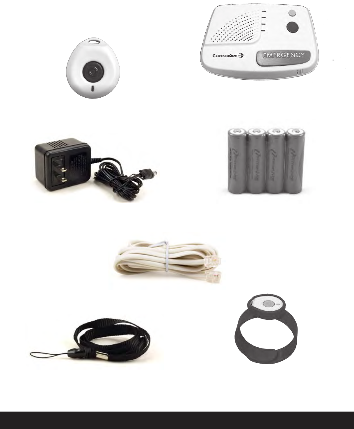
Pendant Part #40915
AC Adapter
Phone Cord
Wrist strapLanyard
Rechargeable AA Batteries - 4 Pieces
Part #35918
System Components:
The items below are included with your System .
Base Unit Part #40914

v3.11 CaretakerSentry® 5
Limitation of Liability
This page is a summary of the Disclaimer and Limited Warranty disclosed in full at the end of this instruction
manual. Read these carefully.
The purchaser agrees by using this CaretakerAlert (the “System”) to the terms and conditions below and in the
Disclaimer and Limited Warranty. The purchaser also agrees to read and follow all instructions and warnings
on the product and contained within these Installation and Operation Instructions.
It will be the sole responsibility of the purchaser and user to assure that this System is installed and programmed
properly, and that the unit is used and maintained correctly. This includes, but is not limited to, periodic use
to assure that the System and batteries, are in proper working order, that the unit is located in an appropriate
location in the home, that the electrical outlet is supplying power, and that the user has been educated as to
the operation and functionality of the product as a whole.
The System’s equipment is not designed or guaranteed to prevent any loss or injury. This Limited Warranty and
Disclaimer of Liability discussed in full at the end of this instruction manual constitutes the terms of sale and use
of the System (and accessories) equipment, and if, notwithstanding these terms of sale and use of the product,
there should arise any liability on the part of LogicMark LLC as a result of any cause whatsoever, regardless of
whether or not such loss, damage, or personal injury was caused by or contributed to by LogicMark’s negligence
to any degree or failure to perform any obligation or strict products liability, such liability will be limited to an
amount paid by the Purchaser for the product.
Further, LogicMark has no obligation to assure that calls are made, received or responded to, nor is LogicMark
responsible for acts, or consequences of the acts, of those responding.
LogicMark provides no monitoring service for this product. It is up to the persons at the numbers called to
respond in an appropriate manner.
6
CaretakerSentry® v3.11
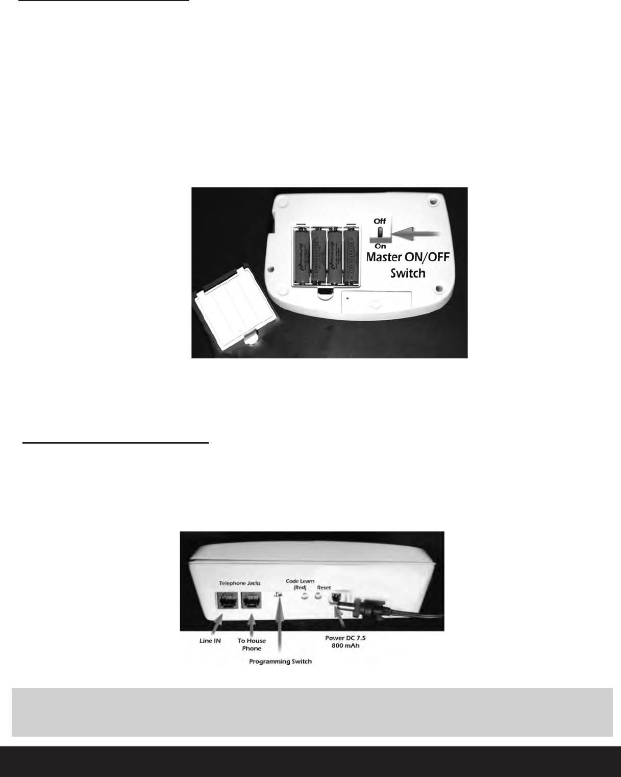
Installing the Batteries:
Base - larger batteries: The Base unit requires 4 rechargeable 2400 mAH NiMH batteries (included). They
will provide you with up 24 hours of battery back- up protection in the event of a power failure. They will not
be damaged by continually charging in the base unit. The ratings on these can be 2400 mAh or higher.
Whenyourstgetyourunit-thesebatterieswillprobablybelow,orevenfullydischarged-andwillneedto
be charged overnight before being able to provide you the 24 hour battery back-up protection.
Remove the cover on the bottom of the Base unit. Install the 4
batteries
as shown in the plastic engraving in
the battery compartment area. A few seconds after you install these, you might hear “Running on battery
power”andREDPowerLEDwillash-whentheunitis operatingon thebackupbatteries.
(If you do not hear this
announcement
and the Power LED is on solid, the unit is already plugged
in to AC power).
Master ON/OFFSwitch:
CaretakerSentry has a Master ON/OFF switch on the bottom of the base unit – just right of the rechargeable
batteries compartment on the base unit. This switch controls all power – back up batteries and power from the
AC adapter. This switch should be ON at all times while the unit is in use. This switch should only be turned
OFF if the CaretakerSentry unit is taken out of service – during transportation or no longer needed.
Connecting the Base Unit:
Power Connection:
Simply plug the AC Adapter into the nearest electrical outlet. Plug the other end of the AC power adapter into
the Base unit. You need to push the plug into the
opening
in the Base unit and twist 90’ clockwise to lock in place.
To
remove
in the future, simply rotate 90’ counter-clockwise and pull outward.
Caution: Do not plug the AC Adapter into an outlet which is controlled by a switch. The switch
could
accidentally
be turned off, thus rendering the Base unit inoperable after approximately 24
hour when the back-up batteries become discharged.
v3.11 CaretakerSentry® 7
Telephone Connection:
A standard telephone line is required to use your
System.
Your phone will work with your existing touch-tone
phone line and existing service. It works the same way as any cordless phone.
NOTE: Touch Tone service is required.
Simply plug one end of the telephone cord into a telephone jack, and the other end into the “Line In” jack
atthebackoftheBaseunit.Note-youwillfeela‘click’whenthecordsarermlyseatedinthewallandthe
Base unit jack receptacles.
If you need to plug a
conventional telephone
into same
outlet
used by the Base unit, simply plug the telephone into
the spare jack labeled “To House Phone.”
Communication Protocol Options:
The CaretakerSentry unit supports 2 different alarm communication protocols – Contact ID and 4+2 - to help
the installer deal with any type of phone System that the customer may be using:
Contact ID alarm communication protocol is not recommended for use with VoIP (Voice over Internet Protocol)
internet phone Systems such as Skype, MagicJack, Basic Talk, Vonage, Comcast, Fox, etc.
Presently
the
reliability
of such
services
is not
adequate
for use with Contact ID in an emergency situation. Check with your central
station for recommendations when your customer is using a VoIP telephone service.
4+2 is a “pulsed” alarm communication format that is much more reliable communication protocol with VoIP
phone Systems – but not all Central Stations support the use of 4+2 communication protocol. Please check
with your Central Station for
recommendations
before using 4+2 on a VoIP phone System.
How to Handle VoIP and other Internet phones: Check with your central station for recommendations
when your customer is using a VoIP telephone service.
Line Seizure:
The phone plugged into the “To House Phone” jack will have the line seizure feature. This means
that whenever the Base unit chooses to dial out during an emergency - it will seize the line from the phone that
is plugged into this “To House Phone” jack if it is in use - and disconnect it - so that the Base unit can dial out.
This is known as ‘Local line seizure’.
Notice: If you choose to have ‘Whole house line seizure’, you need to run all phones through this “To House
Phone” jack. This can only be done with professional installations.
Caution - If the Line Seizure feature is used and hooked-up, verification of Line Seize
capability should be made immediately after installation, and periodically thereafter,
in order to ensure that this equipment can initiate a call even when other equipment
(telephone,
answering System, computer modem, etc.) connected to the same line is in use.

8
CaretakerSentry® v3.11
Dealer Programming Instructions:
The System has several features to help with the programming. The System uses voice prompts and LED lights
toguideyouthroughtheprocess. Theygiveyouagoodaudibleconrmationoftheprogressasyouare
programming. Second are the LED lights on the base unit and the Pendant.
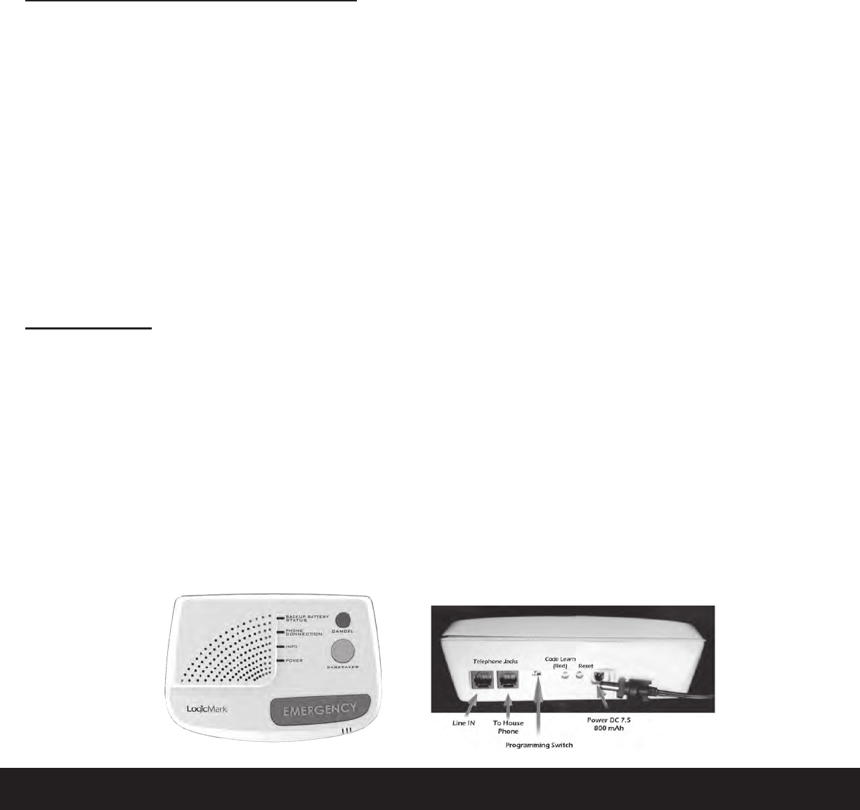
Here is the key for the LEDs:
Key to LED Status - Base Unit:
YELLOW BACK-UP BATTERY STATUS LED functions:
Off: Running on Battery Power
Solid: Normal Operation – Charging Batteries
Flashing: Low or Defective Batteries
BLUE PHONE CONNECTION LED function:
Off: Normal operation
Solid: Dialing/Talking
Flashing: No Phone Connection Detected
GREEN INFO LED functions:
Off: Standby
Solid: Dialing/Talking or Learn Mode
Flashing: Pendant Learning or Problem with Pendant (battery or not communicating)
RED POWER LED functions:
Off: No AC power/No Back-up Battery Power
Solid: AC power
Flashing: Running on Battery Back-up
Programming Central Station Telephone Numbers & Account Codes:
The System must be
programmed
with the central station receiver
telephone
numbers and a 4 digit
account code before unit is operational. The System can learn 2 telephone numbers: the alarm receiver’s
toll free number as the “primary number” and the alarm receiver’s local long distance number as the
“secondary
number” as a back-up, in case the primary number is busy.
NOTES:
• YouprogramtheSystemusingatouch-tonetelephoneconnectedonthesamelineastheBaseunit.You
will hear the Base unit speak each number that is pushed as you push them.
• Dial slowly and listen for each number to be announced. If you did not hear the number
announcement - the number was not recorded.
• The System can learn numbers up to 32 digits long,
• If you chose to only program one central station number, simply enter “#” in place of the second number.
• If you need to add a pause in your number sequence, simply insert a “*” where ever you need a 1 second
pause. Insert “**” if you need a 2 second pause.
• Remember to program a 1 before any long distance numbers.
• Remember to program any AREA CODE numbers if needed.
• Remember to program any PREFIX NUMBERS (like 9 to get an outside line) if needed.
Step1: WriteoutthenumbersyouarewantingtoprogramintotheSystem.Belowwewillrefertotherstphone
number as the
Primary
number, the second phone number as the secondary number. Include area-codes and a 1
or 9 if they are needed for dialing – just like you would need to dial the customers phone from their house.
Step 2: Establish a phone connection with your cell phone. This is done as follows.
From
the
home phone
(on
the same line as the
System
is hooked-up to) call your cell phone (or any other number - if you don’t have a
cellular telephone handy). Answer the phone (or wait until the number called answers the phone and tell
them just to wait a minute while you program your System).

v3.11 CaretakerSentry® 9
Note: If you don’t have an open line when you begin to program the System with your telephone - the phone
company will think you are trying to dial an outside number and will try to complete the call. By having the
phone line already in use with your cell phone or other called party - you are now ready to program the System.
Step 3: With the phone connection established in Step 2, slide the slide switch at the back of the Base unit
to Programming Mode. You will hear an audible announcement of this position.
Step 4: Start programming the System. Push the numbers slowly and listen to the voice prompts. Follow the
next steps to enter the numbers.
NOTE: The “#” key (the key in the lower right corner of your phone keypad) must be entered after the passcode,
after each central station number, and after the account code as shown in the steps below. Do not ignore
the “#” key.
Central Station Number, Account Code, Caretaker Telephone Number Programming:
Note: You will be using your telephone keypad on an open telephone line to program the System numbers.
The base will speak each number that is pushed on the telephones keypad. You DO NOT have to program a
secondary (or back-up) central station telephone number, but we highly recommend it.
1. Call your cell phone from the telephone on the same line as the Base unit. Answer your cellphone
and keep this line open for the following steps.
2. Slide Programming switch to Programming Mode
3. Enter (Passcode) – XXXX then “#”
(Default
is “1 2 3 4”)
[Voice prompt– Enter 1st phone number followed by “#”]
4. Enter primary central station number – X XXX XXX XXXX then “#”
[Voice prompt – Enter 2nd phone number followed by “#”]
5. Note: to skip secondary phone number - just enter “#” again
6.
Enter secondary central station phone number
X XXX XXX XXXX then
“#”
[Voice prompt – Enter 4 digit account number]
7. Enter 4 digit account number – AAAA then “# “ (account number must be 4 digits long – no letters)
[Voice prompt – Enter Caretaker number]
8. Enter Caretaker Number – –
X XXX XXX XXXX then
“#”
[Voice prompt – Programming complete]
(This Caretaker number is the non-emergency number that the CaretakerSentry can call. This is generally
programmed with a nurse or caregiver telephone number. To skip and not program a Caretaker number
– just enter “#” again. If no number is programmed, the Caretaker button will work the same as the
Emergency button)
8. Slide Programming Switch to Normal Operation (“Emergency Call Mode”)
To Change the 4 Digit Passcode:
The factory default for the programming passcode is “1 2 3 4”. If you wish to change this passcode to prevent
unauthorized re-programming, simply follows these steps:
1. Establish a phone line as you did in Step 2 on page 7. Slide programming switch to Programming Mode.
2. Enter “1 2 3 4” or your old Passcode
XXXX then “* # * #”
[Voice prompt – Enter New Passcode ]
3. Enter “Y Y Y Y” (your new passcode) then “#”
[Voice prompt – Programming complete]

10
CaretakerSentry® v3.11
4. Slide Programming Switch to Normal Operation
[Voice prompt – “Emergency Call Mode”]
Note: there is no way to easily reset the passcode if the number is forgotten or mis-programmed, the unit will
have to be exchanged. A forgotten passcode IS NOT a warranty issue. Be careful when changing
passcodes.
Setting Programming Options:
As always - First establish a phone line as you did in Step 2 on page 8. Several options can be
changed during one programming session but you must exit and re-enter the passcode each
time. (You do not have to open a new phone line or slide the switch each time an option is set).
There are nine options that you may wish to set. These are as follows:
• Option #0 – Voice Prompt Language Selection. This changes the language of the voice prompts
between English, Spanish and French (Canadian). Factory setting is English.
• Option #1 -- Dial 9 Before Number. This automatically dials 9 before any of the programmed numbers
are dialed. Only use if 9 is used to dial an outside line. Factory setting is NO
• Option #2 -- Communication Protocol. This is used to select between Contact ID or 4+2. Consult
with your central station before changing. Factory setting is Contact ID.
• Options Option #3 -- Dial *82 before the number. This is used to temporally disable Caller ID blocking.
Consult with your central station before changing. Factory setting is NO.
• Option #4 -- DEMO / Tradeshow Mode. THIS MODE IS FOR DEMO MODE ONLY FOR
SALESPERSONS. This feature is used to DEMO the unit without having access to a telephone line. Use
this feature with a Viking DLE-200 test box. NEVER LEAVE THE UNIT IN THIS MODE FOR NORMAL
OPERATION. Factory setting is NO
• Option #6 -- Automatic Call-Back Feature. This feature allows the unit to call a central station, send
the
Emergency
Event
information,
hang-up and then automatically answer a return call back. After the base
connects with central station, transmits the Personal Emergency and account info and receives the Kiss-Off
tone, the base hangs up. The CaretakerSentry will then answer the next incoming call and the Customer
will speak with the central station with no indication that a callback has occurred. Consult with your central
station before changing. Factory setting is NO
• Option #7 -- Send Restore Message. This option automatically sends Restoral messages to the central
station when a problem with the CaretakerSentry has been corrected. Consult with your central station
before changing. Factory setting is NO
• Option #8 -- Periodic Test Interval. This change the Periodic Test interval between Daily, Weekly and
Monthly. Consult with your central station before changing. Factory setting is Weekly
• Option #9 -- Reset To Factory Settings. This option erases all phone numbers, account numbers and
reset all options back to the factory settings
To Set the Options:
Option #0 – Voice Prompt Language – selects voice prompt language
1. Enter (Passcode) – XXXX then “**” (Default is 1234)
[Voice prompt – Option Mode]
2. Enter – 0 [Voice prompt – Voice Prompt Language],
1 for English – FACTORY SETTING
2 for Spanish
3 for French
3. Enter either 1, 2 or 3
[Voice prompt 1 – English]

v3.11 CaretakerSentry® 11
[Voice prompt 2 – Spanish]
[Voice prompt 3 – French]
4. Enter “#” (to exit programming mode)
[Voice prompt –Programming complete]
5. Slide Programming Switch to “Normal Operation”
Option #1 – Dial 9 Before Number - Dials ‘9’ to get an outside line.
1. Enter (Passcode) – XXXX then “**” (Default is 1234)
[Voice prompt – Option Mode]
2. Enter – 1
[Voice prompt – Dial 9 before number,
1 for YES – 3 for NO]
3. Enter either 1 or 3
[Voice prompt 1 – YES]
[Voice prompt 3 – NO] – FACTORY SETTING
4. Enter “#” (to exit programming mode)
[Voice prompt – Programming complete]
5. Slide Programming Switch to Normal Operation
[Voice prompt – “Emergency Call Mode”]
Option #2 – Alarm Communication Protocol – selects communication language with central station
1. Enter (Passcode) – XXXX then “**” (Default is 1234)
[Voice prompt – Option Mode]
2. Enter – 2 [Voice prompt – Alarm Communication Protocol],
1 for CONTACT ID - FACTORY SETTING
2 for 4+2
3. Enter either 1 or 2
[Voice prompt 1 – CONTACT ID] [Voice prompt 2 – 4+2]
4. Enter “#” (to exit programming mode)
[Voice prompt – Programming complete]
5. Slide Programming Switch to “Normal Operation”
[Voice prompt – “Emergency Call Mode”]
Option #3 -- Dial *82 Before the Number - Displays unblocked Caller ID information from the caller for this
call only.
1. Enter (Passcode) – XXXX then “**” (Default is 1234
[Voice prompt – Option Mode]
2. Enter – 3[Voice prompt – Dial *82 before number,
1 for YES – 3 for NO]
3 .Enter either 1 or 3
[Voice prompt 1 – YES]
[Voice prompt 3 – NO] – FACTORY SETTING
4 .Enter “#” (to exit programming mode)
[Voice prompt – Programming complete]
5. Slide Programming Switch to Normal Operation
[Voice prompt – “Emergency Call Mode”]
Option #4 – DEMO/Tradeshow Mode – THIS MODE IS FOR DEMO MODE ONLY FOR SALESPERSONS.
This feature is used to DEMO the unit without having access to a telephone line. Use this feature with a Viking

12
CaretakerSentry® v3.11
DLE-200 test box. NEVER LEAVE THE UNIT IN THIS MODE FOR NORMAL OPERATION.
1. Enter (Passcode) – XXXX then “**” (Default is 1234)
[Voice prompt – Option Mode]
2. Enter – 4
[Voice prompt – DEMO Tradeshow Mode],
1 for YES 3 for NO– FACTORY SETTING
3. Enter either 1 or 3
[V
oice
prompt 1 – YES] [Voice prompt 3 – NO]
4. Enter “#” (to exit programming mode)
[Voice prompt – Programming complete]
5. Slide Programming Switch to “Normal Operation”
[Voice prompt – “Emergency Call Mode”]
Option #6 -- Automatic Call-Back Feature - This feature allows the unit to call a central station, send the
Emergency
Event
information,
hang-up and then automatically answer a return call back. After the base connects
with central station, transmits the Personal Emergency and account info and receives the Kiss-Off tone, the base
hangs up but keeps the communication link active between the pendant/EWC and itself. .It will then answer
the next incoming call and the Customer will speak with the central station with no indication that a callback
has occurred.
1. Enter (Passcode) – XXXX then “**” (Default is 1234)
[Voice prompt – Option Mode]
2. Enter – 6
[Voice prompt – Automatic Call-back Mode],
1 for YES
3 for NO– FACTORY SETTING
3. Enter either 1 or 3
[V
oice
prompt 1 – YES] [Voice prompt 3 – NO]
4. Enter “#” (to exit programming mode)
[Voice prompt – Programming complete]
5. Slide Programming Switch to “Normal Operation”
[Voice prompt – “Emergency Call Mode”]
Option #7 – Send Restore Message - These are messages that are automatically sent to the central station
to report
the
AC Power or the communication (RF or battery) problem with the Pendant has been restored or
corrected.
1. Enter (Passcode) – XXXX then “**” (Default is 1234) [Voice prompt – Option Mode]
2. Enter – 7
[Voice prompt – Send restore code to call center,
1 for YES – 3 for NO]
3. Enter either 1 or 3
[Voice prompt 1 – YES]
[Voice prompt 2 – NO] – FACTORY SETTING
4. Enter # (to exit programming mode)
[Voice prompt – Programming complete]
5. Slide Programming Switch to Normal Operation
[Voice prompt – “Emergency Call Mode”]
Option #8 - Periodic Test Interval (for automatic check-in with central station)
1. Enter (Passcode) – XXXX then “**” (Default is 1234)
[Voice prompt – Option Mode]
2. Enter – 8

v3.11 CaretakerSentry® 13
[Voice prompt – Periodic test interval,
1 for 1 day,
2 for 7 days,
FACTORY SETTING 3 for 30 days]
3. Enter 1, 2 or 3
[Voice prompt 1 – Every day] [Voice prompt 2 – Every 7 days] [Voice prompt 3 – Every 30 days]
4. Enter “#” (to exit programming mode)
[Voice prompt – Programming complete]
5. Slide Programming Switch to “Normal Operation”
[Voice prompt – “Emergency Call Mode”]
Option #9 – Reset To Factory Settings
1. Enter (Passcode) – XXXX then “**” (Default is 1234)
[Voice prompt – Option Mode]
2. Enter 9
[Voice prompt – Reset to factory settings,
1 for YES – 3 for NO]
3. Enter either 1 or 3
[Voice prompt 1 – YES] [Voice prompt 3 – NO]
4. Enter “#” (to exit programming mode)
[Voice prompt – Programming complete]
5. Slide Programming Switch to “Normal Operation”
[Voice prompt – “Emergency Call Mode”]
Note: The telephone numbers are erased, so if the Emergency button is pushed, you will hear the
dial tone and then “Hanging Up”
REMOTELY PROGRAMMING THE System:
The System can be remotely programmed over a telephone line in one of two ways – Standard and Unaided
Remote Programming.
Standard Method:
1. Simply call the number of the residence where the System is connected.
2. Have the user slide the switch at the back of the base unit to “Programming Mode”.
3. Then, proceed to program the System as needed with the touch-tones of the phone on which you are
calling from.
4. Have them slide the switch back to Normal Operation when done.
Unaided Remote Programming:
1. The dealer calls the customers phone number that the CaretakerSentry is installed on.
2. The dealer allows the phone to ring 1 ring cycle - (equivalent to 1 ring back tone - about 6 seconds of
ringing).
3. The dealer then hangs up.
4. The dealer waits 10 seconds and dials the customer phone number again. The CaretakerSentry sees this
second call within a 30 second period and immediately answers the phon.
• The CaretakerSentry will only start this 30 second timer - waiting for a second call to ring the phone
ONLY if the phone only rings 1 time. If the phone rings more than 1 time, the
CaretakerSentry
unit will
not start the timer and will NOT wait for the second call - feature is canceled and reset.
5. As soon as the CaretakerSentry answers the call, [voice prompt – programming mode] is played.
6. The dealer enters the 4 digit passcode and then CaretakerSentry enters programming mode (unit will
program normally).

14
CaretakerSentry® v3.11
7. If no passcode or an incorrect passcode is entered within 15 seconds, the CaretakerSentry unit will
hang up and
reset.
8. The dealer will press ‘9’ to end programming, exit and reset the CaretakerSentry unit.
Note: The programming voice prompts will still be heard from the base while the unit is being remotely programmed
– this is designed to allow the customer know that changes are being made to their unit.
Adding Additional Pendants to the System:
Note:
When replacing pendants – due to loss or malfunction, ERASE ALL PENDANTS and re-learn just the pendant
that will be used. All pendants are supervised and the base will continue to “look” and send failure messages
to the central station for pendants that are no longer working or not currently being used. SEE SECTION –
ERASING ALL PREVIOUSLY LEARNED PENDANTS
The System comes with one Pendant. If you want to add
additional
pendants (for a combined total of 9) - follow
the directions here - If not, skip this section.
The Pendant’s unique ID code should already be learned into the Base unit when it came from the factory. You
can add additional Pendants (up to 9) to the System by simply teaching each Pendant’s ID code to the Base unit.
When more than 1 Pendant is learned the base, the base unit will announce the Pendant
number - i.e.” Pendant #X, battery is OK” – when only 1 pendant is learned, the base will only
announce “Battery is OK”
Anytime the Pendant reports to the call center (even with pendant battery status), the pendant number
information is also transmitted to the central station – Zone 1, 2, 3,... for Pendants 1, 2, 3,...
To program a new Pendant to the Base unit:
On the Base Unit:
1. Push and release the RED Code Learn button on the back of the Base unit. You will hear a voice prompt
“Pendant Learning”
On the Pendant:
2. PUSH the Gray Emergency Button on the Pendant.
• If“BaseandPendantoutofRange”or,“PendantLearningFailed”isheardfromthependant,
STOP - wait 30 seconds and start at step #1 again.
3. When the Pendant Learning has been successful you will hear “Pendant Code Learned”
•I f “BaseandPendantoutofRange”or,“PendantLearningFailed”isheardfromtheBaseorPendant,
STOP
- wait 30 seconds and start at step #1 again
Notes:
• Yo u have less than 45 seconds after pushing the RED Code Learn button on the base unit to get the pendant
to enter “Pendant Learning” mode.
• Te a c h i n g additional pendants does not erase previously learned pendants. It adds it to the list.The base
unit will automatically exit the pendant learning mode after several seconds or if Pendant Learning Failed
• If you hear the voice prompt “Base and Pendant Out of Range” or, “Pendant Learning Failed” an error has
occurred, wait 30 seconds for the base to reset and repeat steps 1 & 2.
• Only 9 Pendants can be learned. (If Pendants have been lost or replaced, we
recommend
you
erase
all
pendants
and
re-learn
all
current
Pendants.)

v3.11 CaretakerSentry® 15
Erasing All
Previously
Learned Pendants:
Simply holding down the RED Code Learn button at the back of the Base unit for 8 seconds. You will hear the
conrmationof“EraseAllPendants,AllpendantsErased”fromtheBaseunit. Afterthat,youcanprograma
new pendant to the base unit following the steps above as desired.
Basic Set-up and Test:
Lanyard, Wrist Strap
The System comes with 2 accessories for carrying the pendant. You can wear the Pendant using the
Lanyard or Wrist-strap. Note that the Wrist-Strap can also be used as a way to attach the Pendant to a wheel
chair. Choose the method that suits your customer’s needs.
The image above shows the method of attaching the lanyard to the Pendant. Note that the lanyard has a break-
away feature to release if it gets caught on something while around someone’s neck.
System Check:
• The CaretakerSentry has the ability to easily perform a full System check. Press and HOLD the CANCEL
button on the base unit until the base answers “System Check.”
• The GREEN INFO LED will turn on (the base will remain in this System Check mode for 3 minutes).
• You can end the System Check at any time by PUSHING the CANCEL button for 1 second. The base will
announce programming switch position and software version.
Push the Gray Emergency button on the pendant for 2 seconds (multiple pendants can be checked during the
same session) and the base unit will announce:
“All Systems are ok.”
Thisconrmsthefollowing:
• Battery
status
• The Pendant is working. The Base unit is working.
• The Base unit is connected to a working phone line. The Pendant is within range of the Base unit.
“System cannot detect dial tone” / “System cannot detect phone line.”
The Base unit is not connected to the phone line or can not get a dial tone for some reason.
“Base and Pendant out of range” if no pendant was recognized
Thisconrmsoneormoreofthefollowing:
• The Pendant has malfunctioned.
• The Pendant and Base unit are not communicating with each other or are out or range.
Ifyoureceiveafailurenotication,pleaserefertotheTROUBLESHOOTINGguideonpage17 of this manual
to determine the cause.
Remind your customers to perform a System Check at least twice a
month.
NOTE:
The Pendant does
a
self test
on
the pendant battery every
13 hours.
When the battery level gets to the
“Replace battery now”
level,
it will send a signal to the central station to notify them of this
situation.
This pendant does not have any user serviceable parts – if a low battery condition or if failures
occur, the pendant MUST BE replaced.

16
CaretakerSentry® v3.11
The Base also counts these
13
hour
checks. If 4
reports are missed
in a row (52 hours
later),
the Base
unit will send a loss of RF
signal
to the
central
station.
This System Check feature is very useful -allowingyoutoconrmthattheSystemhascoverage
from all parts of the home. Put the base into the test mode and simply walk to the various parts
of your home and push the Gray Emergency button until you hear “Battery is OK” voice prompt.
If you did not hear the voice prompt, check the System more carefully.
NOTE: If your telephone service offers voice mail and the voice mail System uses a Stutter Dial
Tone to notify you of message, the System test may fail – “cannot detect dial tone” if a message
is waiting. This is normal as the CaretakerSentry is “listening” for a conventional dial tone. Check
your messages so the dial tone returns to a solid tone and test again. In the event of an emergency,
the CaretakerSentry will dial the emergency number regardless of a standard or stutter dial tone.
Operating Range:
The operating range of the System will depend on many factors including intervening walls, electrical interference
or various appliances such as vacuum cleaners, refrigerators, microwave ovens, mixers, coffee grinders, hair
dryers and other sources of electrical noise around the house. The System should cover the entire home and
a short distance into the front, side and back yards. Perform the System Check on page 15 to determine the
boundaries of the System to know the limits of operation in your home and surroundings.
Testing:
Be sure to have your subscriber (customer) fully test the System with the central station. Please keep in mind -
when using the 433 MHz 1-way pendant, the pendant will activate the base unit well beyond the voice
audible range of the speaker and microphone. Please consult with your customer and central
station on procedures and policies if the central station receives a emergency call but they cannot
communicate with your customer.
Out of Service Storage or Transportation:
When storing the Base unit -or taking it on a trip - or sending it in for repair - it is
recommended
that you turn the
Master ON / OFF switch to OFF so that the “Running on battery power” announcement doesn’t repeat for the
next 24 hours. Remember to turn the Master ON / OFF switch ON in the Base unit when it is put back in service.
Caution - If the Line Seizure feature is used and installed the installer, customer or user must verify
that the telephone line and equipment will work properly when the System is turned OFF and/
or removed from service.

v3.11 CaretakerSentry® 17
TROUBLESHOOTING
GUIDE:
What if I can’t get the System to work?
Step 1 – Push the Black RESET button with a pen at the back of the Base unit (next to the power cord).
Check the System. If it is now working skip the remaining steps.
Step 2 – Check the PENDANT.
What to do:
Press the Gray Emergency button and look for the RED LED to turn ON
What to expect:
The RED LED on the pendant should turn ON for 2 seconds
If nothing happens, the most likely cause is that the battery in the pendant is dead – make plans to replace
the pendant as soon as possible.
Step 3 – Check the connections on the BASE UNIT
What to do:
Make sure the AC Adapter is plugged into a live AC outlet and into the Base unit. Make sure the
Master ON / OFF switch is ON.
What to expect:
The Red POWER LED will be on solid if the Base unit is connected to power.
TheBluePHONECONNECTIONLEDshouldbeOFF–ifashing,thereisproblemwiththephone
connection.
If the POWER light is on and the Base unit is connected to a working phone line, go on to step 4.
Step 4 – Make sure the Pendant and the Base unit are communicating with each other.
Background information: The Pendant and the Base unit are connected by a
wireless radio
link.
They must
be
synchronized
to work together.
They
should have already been synchronized at the factory, but resetting this is
simple.
What to do: Follow the steps on page 14: Adding Additional Pendants to the System
Now perform the System Check test again (page 15) to make sure all is well.
If the System is still not working, call tech support. See page 24 for telephone number.

18
CaretakerSentry® v3.11
Central Station Items of Interest:
Number of call attempts: 9 times - alternating between the
rstand
second
numbers programmed.
Supervision of Pendants Yes – all pendants check in with the Base every 13 hours. A Pe
ndant
mi
ssing for
more
tha
n 52 hours signals a “Loss of RF” condition/report.
Reporting of Low Pendant Battery to Central Station
Upon receipt of
rst
“Replace Battery Now” Reporting of AC Power Loss After 8 hours
of power loss - and only once. Reporting of Restore Codes Only once after restore
condition met.
(Dealer programmable feature).
Operator Commands It can communicate in Duplex of Simplex mode. Call starts in Duplex but can be
switched to Simplex at any time by pushing 1 to talk and 3 to Listen
Unlimited talk time; but System will hang-up after 3 minutes of silence.
“4” will switch back to duplex mode
“7” will extend time another 3 minutes
“9” will force a hang-up and reset
Pendant battery life 5 year service life - estimated
ContactIDEventCodeProle: StandardAdemcoContactID
Contact ID Event Codes Sent:
1-101 Personal Emergency (personal emergency)
1-606 Listen-in to follow (request for voice call)
1-301 AC Loss (AC power loss longer than 8 hours)
3-301 Restoral - AC Loss
1-381 Loss of Radio supervision (pendant has not reported to the base in the last 52 hours, four 13 hour cycles)
3-381 Restoral - Loss of Radio supervision
1-384 RF low battery (pendant batter is < 3.5 volts)
3-384 Restoral - RF low battery
1-602
Periodic
test
report (periodic intervals
are
installer programmable
to 1, 7 or 30 days - default is 7 days)
Note: Each pendant is set up as a
Zone -
if
a
pendant event code
is
sent, the central s
tation
can know w
hich
pendant
initiated the call
(only if the
installer
notiesthecentralstationwhichpersoncarrieseachpendant).
4+2EventCodesProle:
01, 02, 03, 04
Medical
Alarms, zones 1, 2, 3, 4
40 A/C Fail
50 A/C Restoral
61, 62, 63, 64 R/F Loss of Supervision, zones 1, 2, 3, 4
71, 72, 73, 74 R/F Restoral of Supervision, zones 1, 2, 3, 4
41, 42, 43, 44 R/F Low Battery, zones 1, 2, 3, 4
51, 52, 53, 54 R/F Battery Restoral, zones 1, 2, 3, 4
30 Timer Test
Note: Each pendant & EWC is treated as a separate zone

v3.11 CaretakerSentry® 19
Information The FCC Wants You To Know:
Caretaker Sentry Base Unit - Model 40914
FCC ID: TYD-CS40914
IC: 8471A-CS40914
Caretaker Sentry Standard Pendant - Model 40915
FCC ID: TYD-CS40915
IC: 8471A-CS40915
Changesormodicationsnotexpresslyapprovedbythepartyresponsibleforcompliancecouldvoidthe
user’s authority to operate the equipment.
This device complies with Part 15 of the FCC Rules. Operation is subject to the following two conditions:
(1) this device may not cause harmful interference, and (2) this device must accept any interference
received, including interference that may cause undesired operation.
This equipment has been tested and found to comply with the limits for a Class B digital device, pur-
suant to Part 15 of the FCC Rules. These limits are designed to provide reasonable protection against
harmful interference in a residential installation. This equipment generates uses and can radiate radio
frequency energy and, if not installed and used in accordance with the instructions, may cause harmful
interference to radio communications. However, there is no guarantee that interference will not occur in
a particular installation. If this equipment does cause harmful interference to radio or television recep-
tion, which can be determined by turning the equipment off and on, the user is encouraged to try to
correct the interference by one of the following measures:
- Reorient or relocate the receiving antenna.
- Increase the separation between the equipment and receiver.
- Connect the equipment into an outlet on a circuit different from that to which the receiver is con-
nected.
- Consult the dealer or an experienced radio/TV technician for help.
This portable transmitter with its antenna complies with FCC/IC RF exposure limits for general popula-
tion/uncontrolled exposure.
This Device complies with Industry Canada License-exempt RSS standard(s). Operation is subject to the
following two conditions: 1) this device may not cause interference, and 2) this device must accept any
interference, including interference that may cause undesired operation of the device.
Cet appareil est conforme à Industrie Canada exemptes de licence RSS ou les normes. Opération est
sujette aux deux conditions suivantes: 1) cet appareil ne doit pas brouillage et 2) cet appareil doit
accepter toute interférence reçue, y compris les interférences pouvant entraîner un fonctionnement
indésirable du dispositif.
This equipment complies with Part 68 of the FCC rules and the requirements adopted by the ACTA:
US: TBD
REN: 3.7
Privacy of communications may not be ensured when using this product.
ThisproductmeetstheapplicableIndustryCanadatechnicalspecications./Leprésentmatérielestconformeauxspecica-
tions techniques applicables d’Industrie Canada.
The Ringer Equivalence Number (REN 3.7) is an indication of the maximum number of devices allowed to be connected to a
telephone interface. The termination of an interface may consist of any combination of devices subject only to the require-
mentthatthesumoftheRENsofallthedevicesnotexceedve./L’indiced’équivalencedelasonnerie(IES)sertàindiquer
le nombre maximal de terminaux qui peuvent être raccordés à une interface téléphonique. La terminaison d’une interface
peut consister en une combinaison quelconque de dispositifs, à la seule condition que la somme d’indices d’équivalence de
la sonnerie de tous les dispositifs n’excède pas cinq.

20
CaretakerSentry® v3.11
General Warnings And Precautions!
Warning!
- LogicMark, LLC DOES NOT represent this unit to be waterproof. To reduce the risk of damage to the
unit, DO NOT expose the pendant or base unit to prolonged water, rain or moisture.
- This System is intended for residential use only. It may not work properly if connected to some com-
mercial phone Systems.
- This System works with tone dialing Systems only. Do not use if you have pulse dialing only. The System
cannot be connected to cellular telephone service, MagicJack, Skype or similar virtual telephone services.
- This product and/or accessories may contain lead, a chemical known to the State of California to cause
birth defects or other reproductive harm.
Note: The System does not interfere with pacemakers.
Important Safety Instructions:
When using your System , please observe the following instructions in order to reduce the risk
ofpersonalinjury,electricalshock,orre.
1. Save these instructions for future reference.
2. Read all instructions carefully and make sure you understand them.
3. Unplug this product from the electrical outlet before attempting to clean it. Do not use any liquids for
cleaning either the Base unit or the Pendent. Use only a soft damp cloth.
4. Do not locate the Base unit near any source of water, such as in the bathroom, near a sink in the
kitchen, or the like.
5. Do not open the unit, (except the battery compartments as directed in these instructions) on the
Pendant for any reason. Any attempt to open the case of the Base unit or the Pendant will void the
warranty and may damage the unit or prevent it from working properly.
6. Donotuseanypowersourceotherthanthatsuppliedwiththisproductspecicallyforthisproduct.
Use of any other power source could damage your unit or make it unsafe.
7. Alwaysdisposeofbatteriesproperly.Neverthrowbatteriesintoare.Consultyourlocalordinances
for proper battery safety.
8. If your unit becomes damaged do not attempt to repair it. Please return it to your dealer or service
provider for service or replacement as stipulated on the next page under “ONE YEAR LIMITED WAR-
RANTY”.
LogicMark Disclaimers and Limited Warranty
COMMUNICATION AND RESPONSE LIMITATIONS: Purchaser acknowledges that signals which are
transmitted over telephone lines, or other modes of communication pass through communication networks
wholly beyond the control of LogicMark LLC and are not maintained by LogicMark LLC, and, therefore, Log-
icMark LLC shall not be responsible for any equipment or communication failure which prevents transmission
signals from reaching your contact list including emergency 911 operators or damages arising therefrom.
Purchaser acknowledges that LogicMark LLC provides no response to the System’s equipment.
The equipment is designed to communicate with the a central station of your choice and LogicMark LLC is not
and shall not be responsible for ambulance, police or other emergency response time or that any response
will be provided by the central monitoring station.
ELECTRIC AND TELEPHONE SERVICE IS NECESSARY AND PURCHASER’S RESPONSIBILITY:
Purchaser acknowledges that the System’s equipment plugs into a standard land line telephone jack and
communicates over standard telephone lines using two way voice communication. Purchaser acknowledges
that the System’s equipment requires 110 Volt AC power and electrical outlets and receptacles, telephone
hook-ups, RJ11 Block or equivalent, all of which is Purchaser’s responsibility to obtain and maintain.
TESTING AND SERVICE OF THIS EQUIPMENT: The equipment, once installed, are in the exclusive pos-
session and control of the Purchaser, and it is Purchaser’s sole responsibility to test the operation of equipment
and request warranty service if the equipment is under warranty.

v3.11 CaretakerSentry® 21
PURCHASER’S EXCLUSIVE REMEDY: Purchaser’s exclusive remedy for LogicMark LLC’s default hereunder is
to require LogicMark LLC to repair or replace, at LogicMark LLC’s option, any equipment or part of the personal
emergency alert System which is non-operational during LogicMark LLC’s warranty period.
LIMITATION OF LIABILITY: This equipment is not designed or guaranteed to prevent any loss or injury.
This Limited Warranty and Disclaimer of Liability constitutes the terms of sale and use of the System (and
accessory) equipment, and if, notwithstanding these terms of sale and use of the product, there should arise
any liability on the part of LogicMark LLC as a result of any cause whatsoever, regardless of whether or not
such loss, damage, or personal injury was caused by or contributed to by LogicMark LLC’s negligence to any
degree or failure to perform any obligation or strict products liability, such liability will be limited to an amount
paid by the Purchaser to LogicMark LLC for the product, or to the sum of $350.00, whichever is greater.
ONE YEAR LIMITED WARRANTY
Warranty: LogicMark, LLC warrants to the original consumer/purchaser that this product shall be free of
defects in material and workmanship under normal use and circumstances for a period of one (1) year from
the date of original purchase for use.
How to Get Warranty Service: All warranty service must go through your dealer or service provider. If
for some reason this is not doable, then the original consumer/purchaser can return the product pre-paid to
LogicMark, LLC; 10106 Bluegrass Pkwy; Louisville KY, 40299, USA within the warranty period, and if the product
is defective, LogicMark, LLC will at its option repair or replace such.
Warranty Limitations and Exclusions: LogicMark LLC does not represent nor warrant that this System will
prevent any loss, damage or injury to person or property, or that the personal emergency alert System will in
all cases provide the protection for which it is installed or intended. Purchaser acknowledges that LogicMark
LLC is not an insurer, and that Purchaser assumes all risk for loss or injury to Purchaser’s property or person.
LogicMark LLC has made no representation or warranties, except those expressed herein and hereby disclaims
anyexpresswarrantyofmerchantabilityortnessforanyparticularuse.
LogicMark, LLC. will not be responsible for the improper use of this System, nor will it be responsible for failure
resulting from the use of other equipment connected to the same phone line. We will not be responsible for
the quality of the phone line or the reliability or quality of the phone service with which the System is used.
LogicMark, LLC. will not be responsible for the installation of the System. It will not be responsible for the
improper use or abuse of the base unit or pendant.
This warranty shall constitute the sole liability of LogicMark, LLC concerning the product. ALL IMPLIED WAR-
RANTIES INCLUDING, WITHOUT LIMITATION, THE WARRANTIES OF MERCHANTABILITY AND FITNESS FOR
A PARTICULAR PURPOSE ARE LIMITED IN DURATION TO THE TERM OF THIS EXPRESSED ONE YEAR LIMITED
WARRANTY. NO PERSON, FIRM, OR CORPORATION IS AUTHORIZED TO ASSUME FOR LogicMark, LLC. ANY
OTHER LIABILITY IN CONNECTION WITH THE SALE AND USE OF THE PRODUCT. LogicMark, LLC AND AGENTS
AND DISTRIBUTORS WILL BEAR NO LIABILITY WHATSOEVER FOR INCIDENTAL OR CONSEQUENTIAL DAM-
AGES OR CHARGES OF ANY KIND
This warranty is void if the product has been damaged or tampered with or if the product or any such parts
havebeenopened.Inallcasesofdamageduringshipment,aclaimmustbeledwiththeshippingcarrier
and not with LogicMark, LLC.
State Law:Thiswarrantygivesyouspeciclegalrights;youmayalsohaveotherrightswhichvaryfrom
state to state. Some states to not allow the exclusion or limitation of incidental or consequential damages, or
a limitation on the duration of implied warranties, so the above disclaimers may not apply to you
OUT OF WARRANTY REPAIRS
As with all warranty repairs - you need to work through your dealer or service provider. If the warranty period
has expired or if you are not the original owner of the product, LogicMark, LLC will at its option either (1)
replace this product with a functionally similar (but not necessarily identi cal) refurbished product or (2) repair
the original product and return it to the original consumer/purchaser after payment of repair/replacement
charges has been received.
22
CaretakerSentry® v3.11
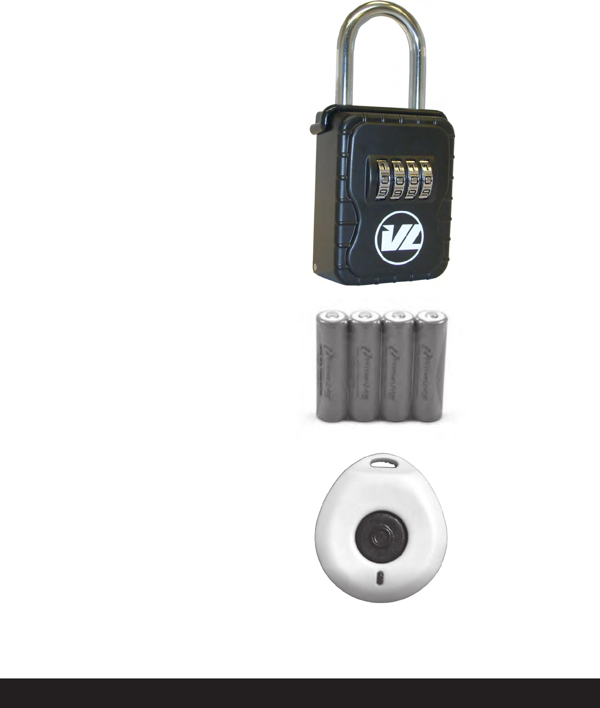
Rechargeable
AA
Batteries
4
Pieces
Part #35918 $15.95
Lock
Box
Part #30913 $34.95
Extra Pendants
Part #40915
Replacement Parts / Optional Accessories
All prices are shown are MSRP and are in US Dollars

v3.11 CaretakerSentry® 23
ProductSpecications:
RF Characteristics: 433 MHz – 1 way pendant
Switchable Duplex or Simplex voice
communication through base.
Communication
Protocols Two options:
Ademco Contact ID / 4+2
Operating Range Covers your typical American
house
and into the front, back, and side yards.
Up to 600 feet line-of-sight from Base
unit.
Power Adapter Ratings Input: 110
VA C
Output: 7.5 volts DC - 800 mA
Base Unit Power Consumption 60 mA in standby
mode
200 mA when
dialing
Back-up Battery Supply
AA
NiMH 2,400 mAh batteries (4 pieces). Should be replaced
every several
years to maintain proper charge during standby times.
Back-up
Operation Duration: 24 hours with fresh
batteries
Dialing Style Touch-Tone only
Telephone Number Length 32 digits
maximum
Telephone Numbers Can learn up to 2 central station
numbers,
both a Primary and a Secondary
back-up.
Pendant Battery Life 5 year service life (estimated)
Operating
Temperature 32˚ to 120˚ F. ( 0 ˚ to 49˚ C).
Pedant water-resistance Water Spray Standard IPX7
(Submersion 3’ – 30 minutes
).
Number of learned
Pendants per Base
9 Pendants

24
CaretakerSentry® v3.11
10106 Bluegrass Pkwy
Louisville KY, 40299
Tel: 1-502-410-0402
Toll Free: 1-888-283-6516
Fax: 1-703-934-7935
www.LogicMark.com
©2013 LogicMark, LLC