LogicMark CS40914 Caretaker Sentry Base Unit User Manual manual
LogicMark, LLC Caretaker Sentry Base Unit manual
UserManual.wiki
>
LogicMark
>
CS40914 User Manual
>
manual
Contents
1.
manual
2.
15_40914 UserMan
manual
Navigation menu
Upload a User Manual
Namespaces
Wiki Guide
HTML
PDF
Info
Views
User Manual
Discussion / Help
Navigation

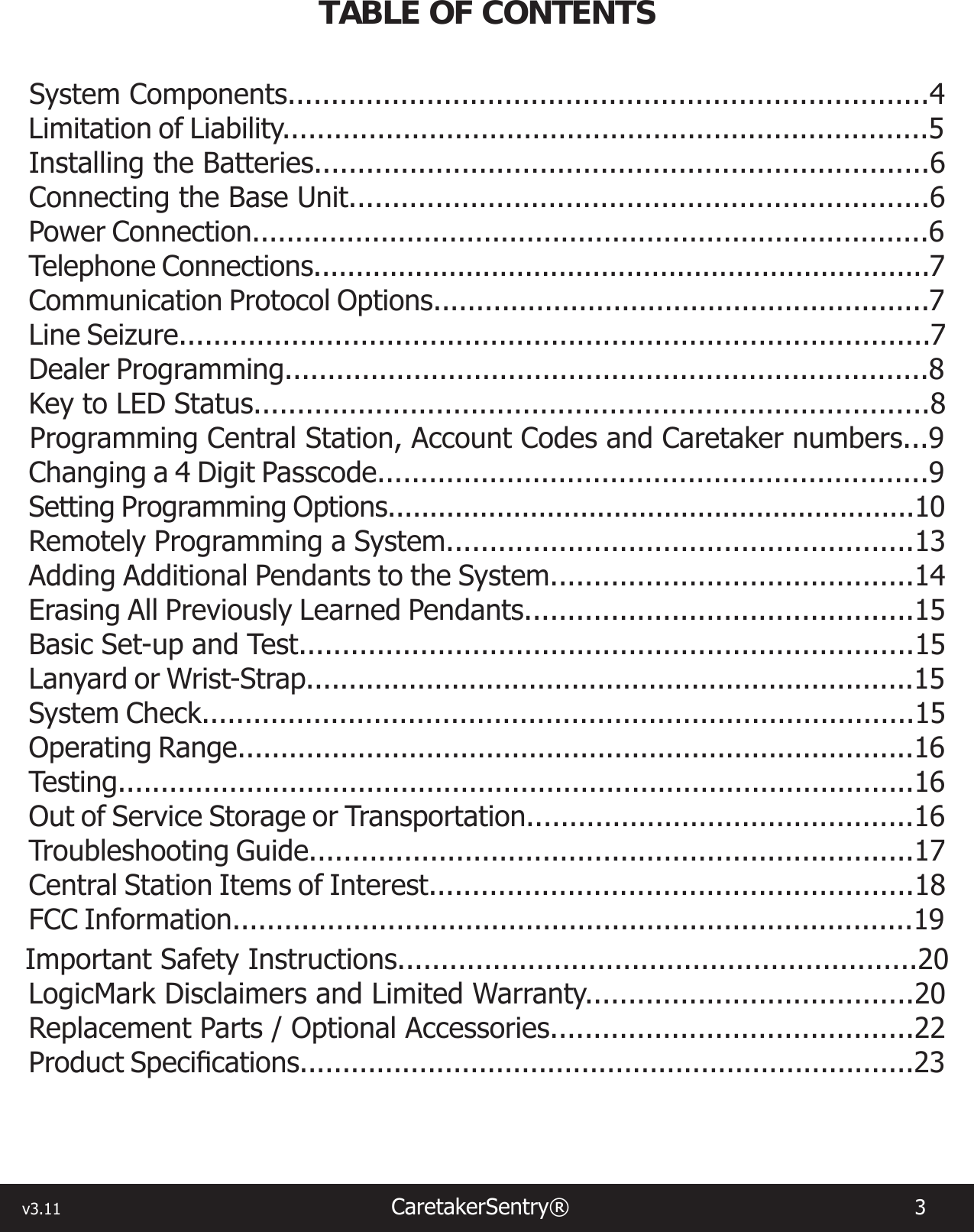
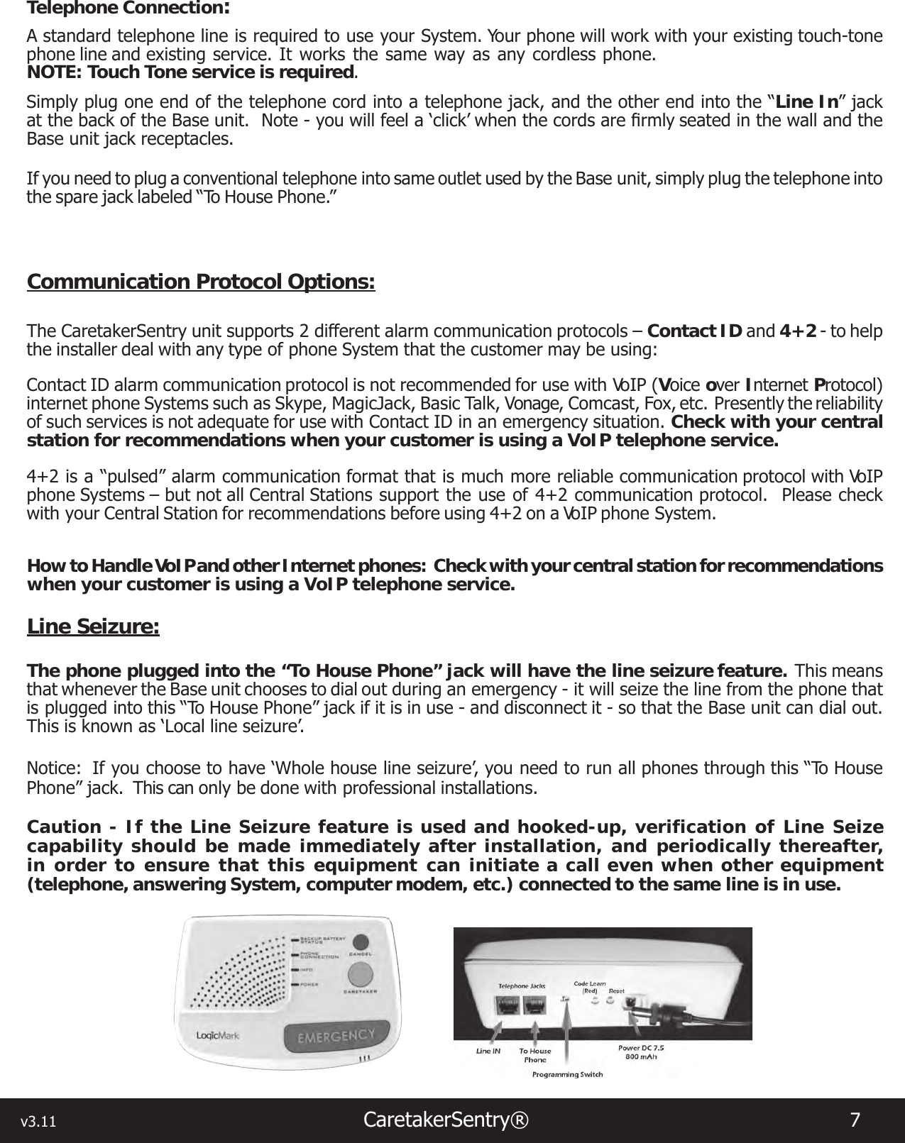
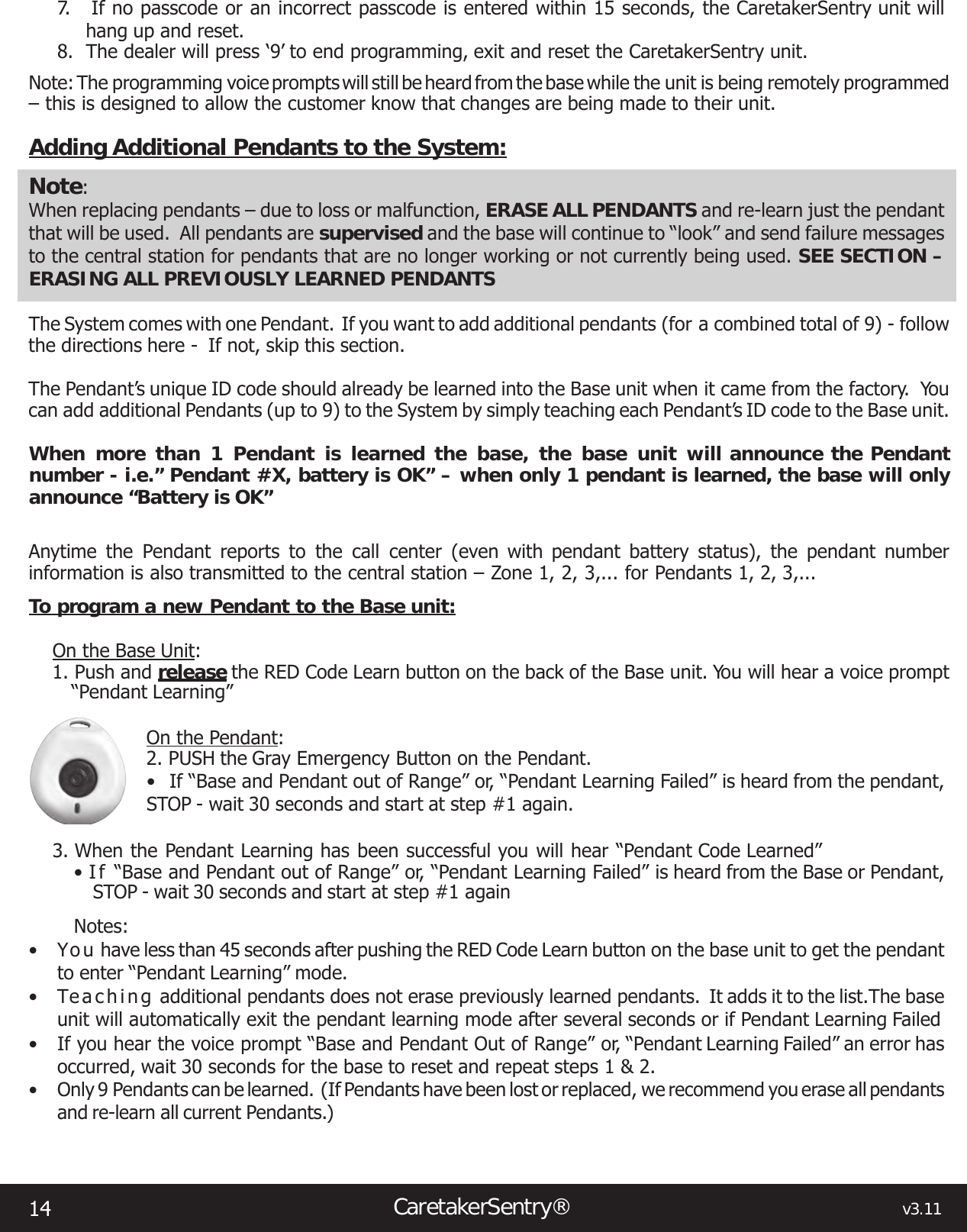
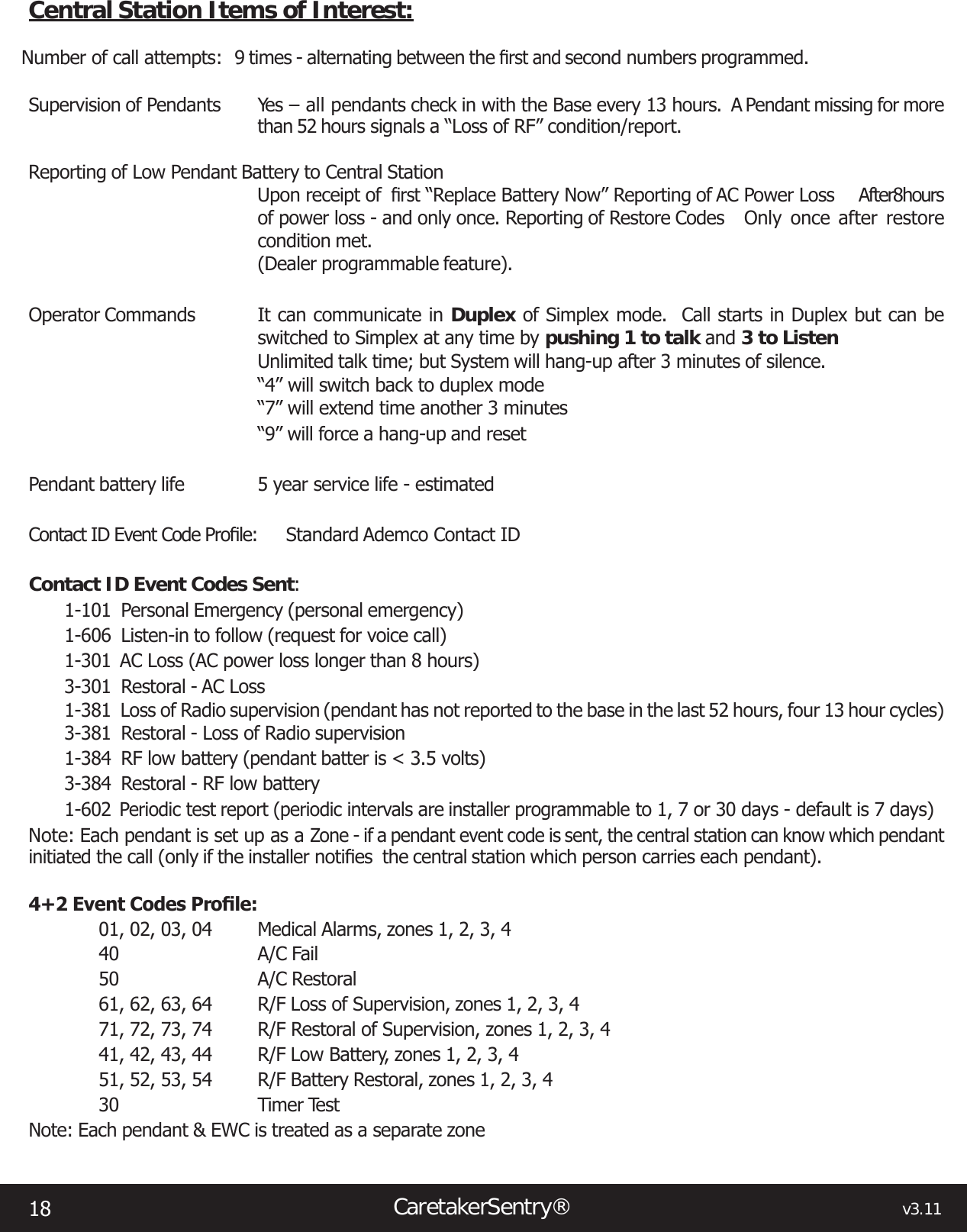
![v3.11 CaretakerSentry® 9 Note: If you don’t have an open line when you begin to program the System with your telephone - the phone company will think you are trying to dial an outside number and will try to complete the call. By having the phone line already in use with your cell phone or other called party - you are now ready to program the System.Step 3: With the phone connection established in Step 2, slide the slide switch at the back of the Base unit to Programming Mode. You will hear an audible announcement of this position.Step 4: Start programming the System. Push the numbers slowly and listen to the voice prompts. Follow the next steps to enter the numbers.NOTE: The “#” key (the key in the lower right corner of your phone keypad) must be entered after the passcode, after each central station number, and after the account code as shown in the steps below. Do not ignore the “#” key.Central Station Number, Account Code, Caretaker Telephone Number Programming:Note: You will be using your telephone keypad on an open telephone line to program the System numbers. The base will speak each number that is pushed on the telephones keypad. You DO NOT have to program a secondary (or back-up) central station telephone number, but we highly recommend it.1. Call your cell phone from the telephone on the same line as the Base unit. Answer your cellphone and keep this line open for the following steps.2. Slide Programming switch to Programming Mode3. Enter (Passcode) – XXXX then “#” (Default is “1 2 3 4”) [Voice prompt– Enter 1st phone number followed by “#”]4. Enter primary central station number – X XXX XXX XXXX then “#” [Voice prompt – Enter 2nd phone number followed by “#”]5. Note: to skip secondary phone number - just enter “#” again6. Enter secondary central station phone number X XXX XXX XXXX then “#” [Voice prompt – Enter 4 digit account number]7. Enter 4 digit account number – AAAA then “# “ (account number must be 4 digits long – no letters) [Voice prompt – Enter Caretaker number]8. Enter Caretaker Number – – X XXX XXX XXXX then “#” [Voice prompt – Programming complete](This Caretaker number is the non-emergency number that the CaretakerSentry can call. This is generally programmed with a nurse or caregiver telephone number. To skip and not program a Caretaker number – just enter “#” again. If no number is programmed, the Caretaker button will work the same as the Emergency button)8. Slide Programming Switch to Normal Operation (“Emergency Call Mode”)To Change the 4 Digit Passcode:The factory default for the programming passcode is “1 2 3 4”. If you wish to change this passcode to prevent unauthorized re-programming, simply follows these steps:1. Establish a phone line as you did in Step 2 on page 7. Slide programming switch to Programming Mode.2. Enter “1 2 3 4” or your old Passcode XXXX then “* # * #” [Voice prompt – Enter New Passcode ]3. Enter “Y Y Y Y” (your new passcode) then “#” [Voice prompt – Programming complete]](https://usermanual.wiki/LogicMark/CS40914.manual/User-Guide-2168108-Page-9.png)
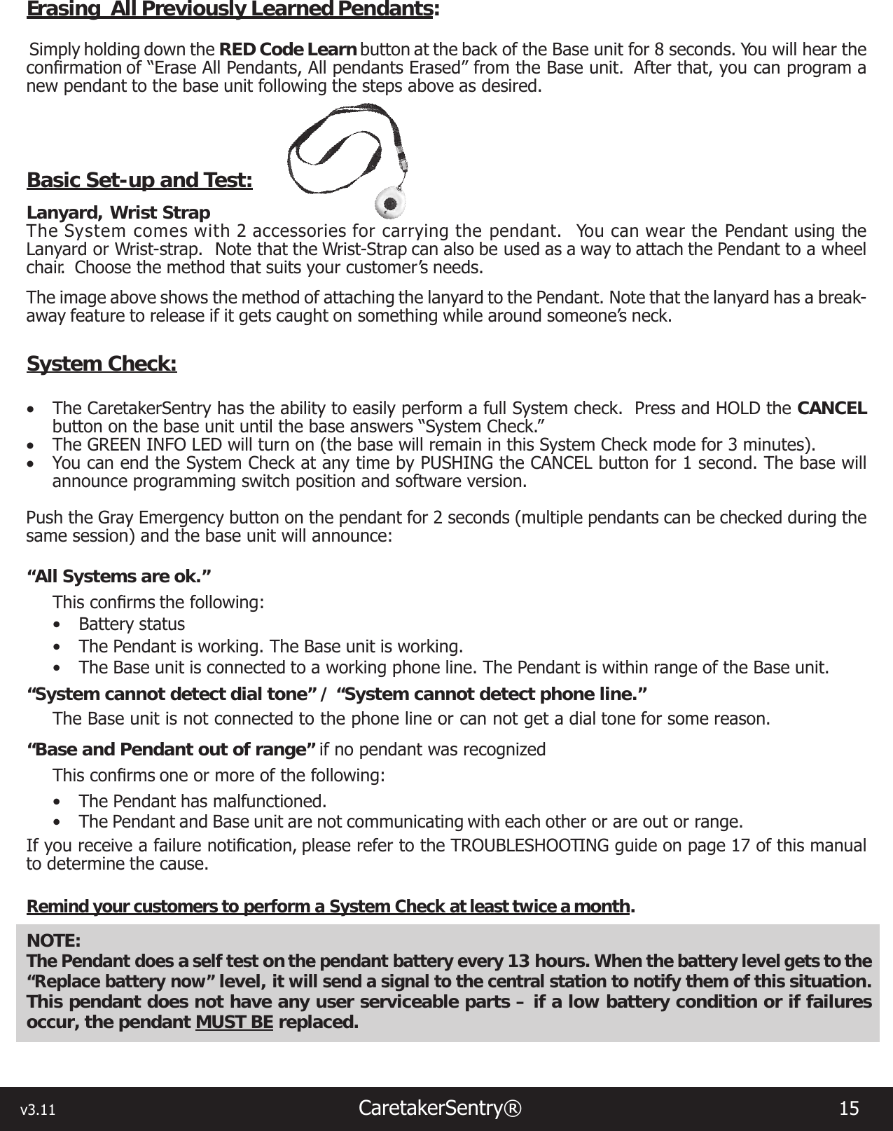
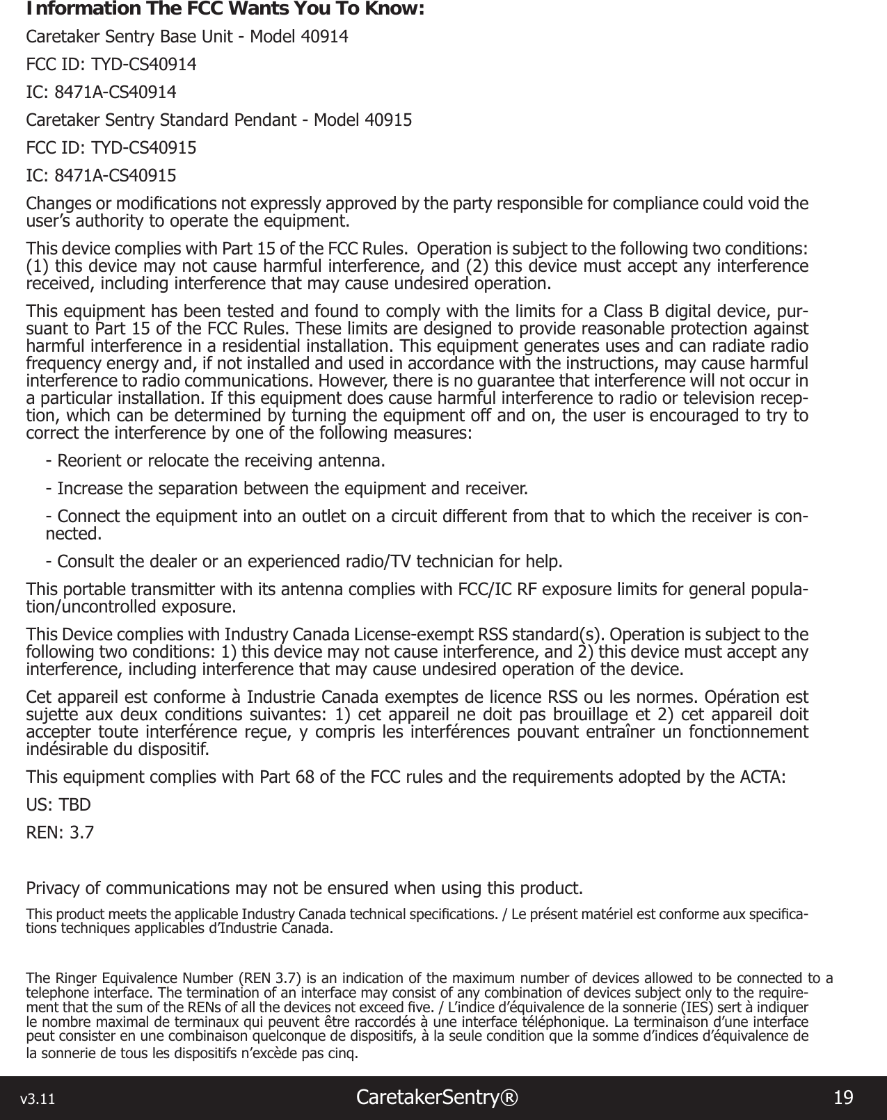
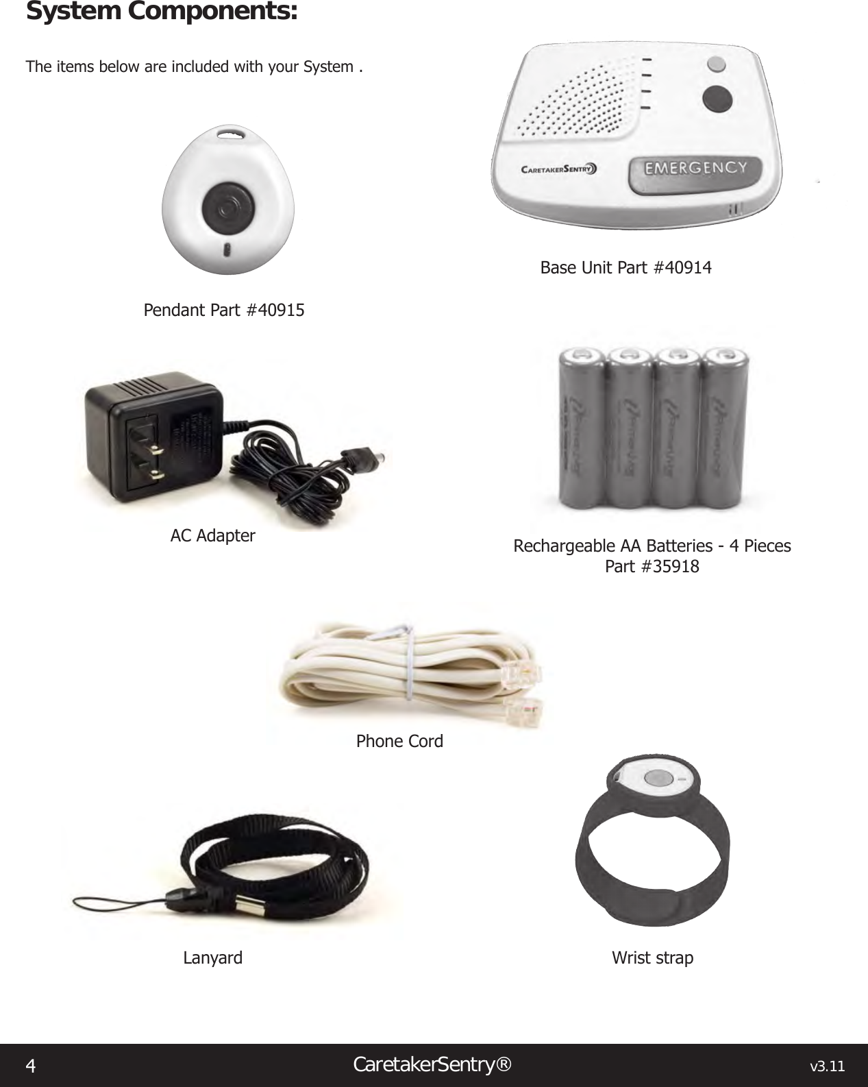
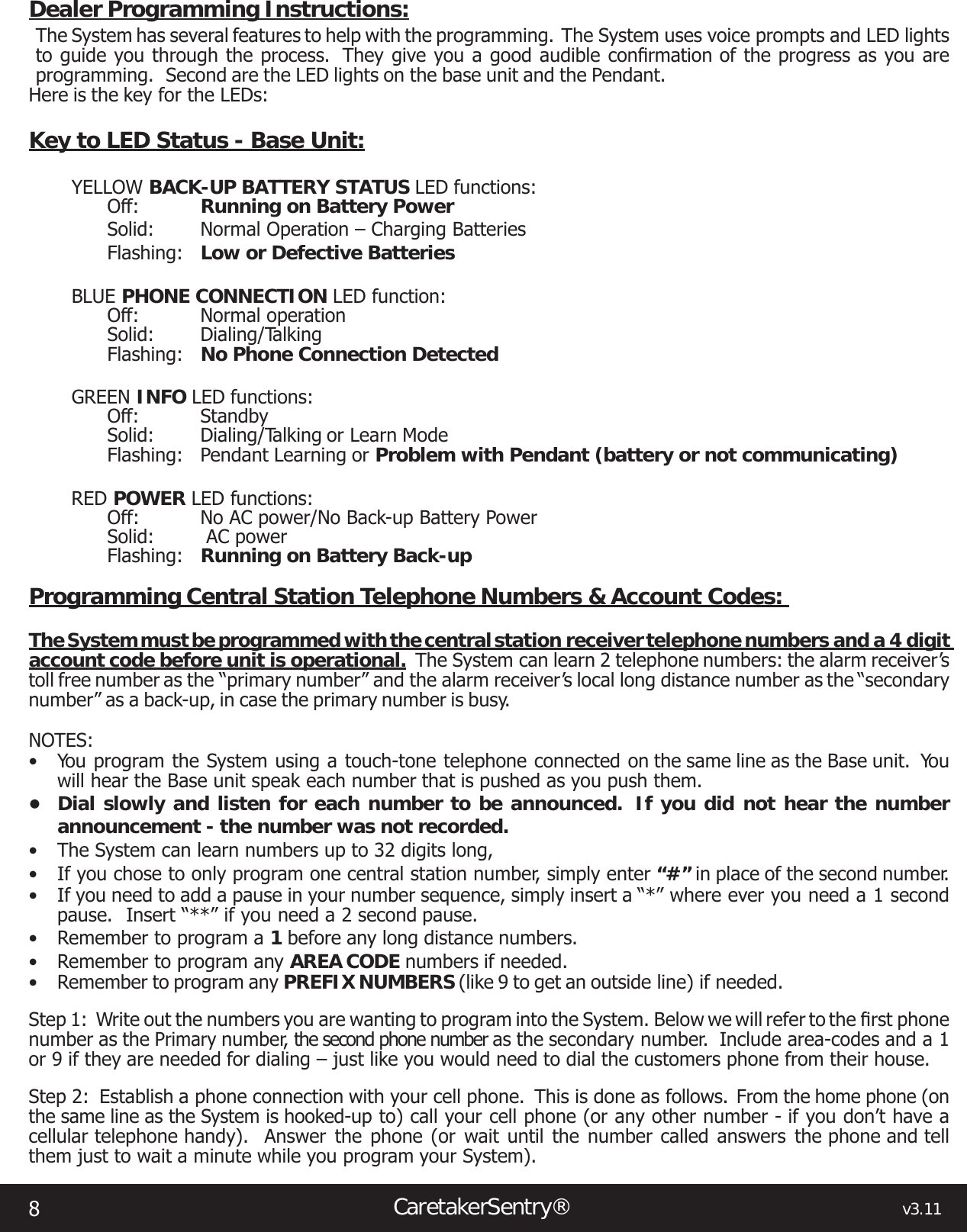
![10CaretakerSentry® v3.114. Slide Programming Switch to Normal Operation [Voice prompt – “Emergency Call Mode”]Note: there is no way to easily reset the passcode if the number is forgotten or mis-programmed, the unit will have to be exchanged. A forgotten passcode IS NOT a warranty issue. Be careful when changing passcodes.Setting Programming Options:As always - First establish a phone line as you did in Step 2 on page 8. Several options can be changed during one programming session but you must exit and re-enter the passcode each time. (You do not have to open a new phone line or slide the switch each time an option is set).There are nine options that you may wish to set. These are as follows: • Option #0 – Voice Prompt Language Selection. This changes the language of the voice prompts between English, Spanish and French (Canadian). Factory setting is English.• Option #1 -- Dial 9 Before Number. This automatically dials 9 before any of the programmed numbers are dialed. Only use if 9 is used to dial an outside line. Factory setting is NO• Option #2 -- Communication Protocol. This is used to select between Contact ID or 4+2. Consult with your central station before changing. Factory setting is Contact ID.• Options Option #3 -- Dial *82 before the number. This is used to temporally disable Caller ID blocking. Consult with your central station before changing. Factory setting is NO.• Option #4 -- DEMO / Tradeshow Mode. THIS MODE IS FOR DEMO MODE ONLY FOR SALESPERSONS. This feature is used to DEMO the unit without having access to a telephone line. Use this feature with a Viking DLE-200 test box. NEVER LEAVE THE UNIT IN THIS MODE FOR NORMAL OPERATION. Factory setting is NO• Option #6 -- Automatic Call-Back Feature. This feature allows the unit to call a central station, send the Emergency Event information, hang-up and then automatically answer a return call back. After the base connects with central station, transmits the Personal Emergency and account info and receives the Kiss-Off tone, the base hangs up. The CaretakerSentry will then answer the next incoming call and the Customer will speak with the central station with no indication that a callback has occurred. Consult with your central station before changing. Factory setting is NO• Option #7 -- Send Restore Message. This option automatically sends Restoral messages to the central station when a problem with the CaretakerSentry has been corrected. Consult with your central station before changing. Factory setting is NO• Option #8 -- Periodic Test Interval. This change the Periodic Test interval between Daily, Weekly and Monthly. Consult with your central station before changing. Factory setting is Weekly• Option #9 -- Reset To Factory Settings. This option erases all phone numbers, account numbers and reset all options back to the factory settingsTo Set the Options:Option #0 – Voice Prompt Language – selects voice prompt language1. Enter (Passcode) – XXXX then “**” (Default is 1234) [Voice prompt – Option Mode]2. Enter – 0 [Voice prompt – Voice Prompt Language],1 for English – FACTORY SETTING2 for Spanish 3 for French3. Enter either 1, 2 or 3[Voice prompt 1 – English]](https://usermanual.wiki/LogicMark/CS40914.manual/User-Guide-2168108-Page-10.png)
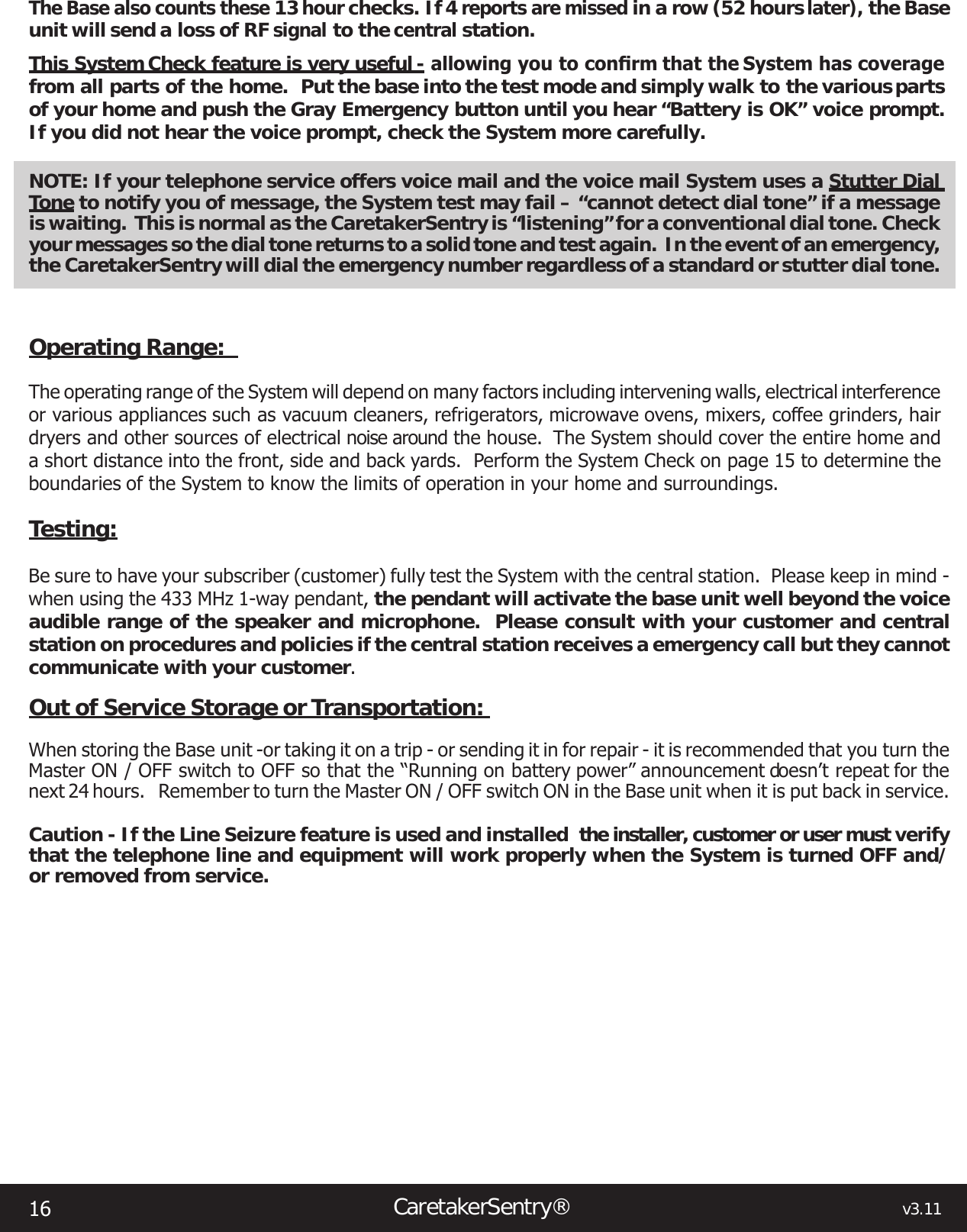
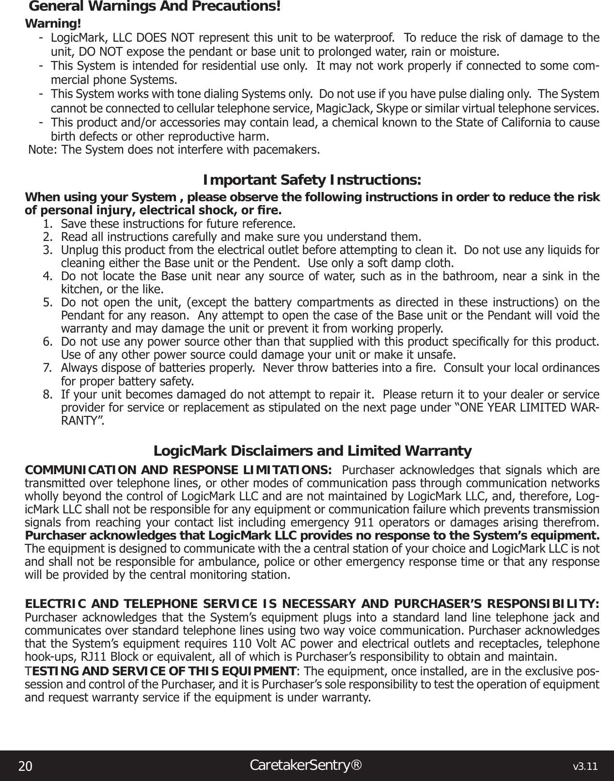
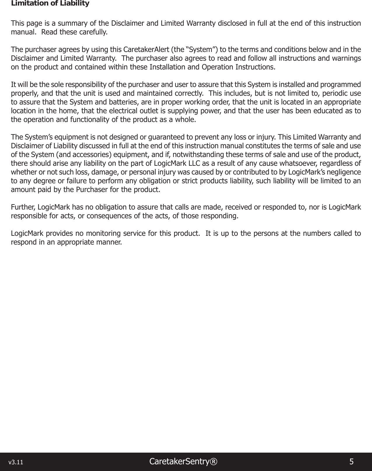
![v3.11 CaretakerSentry® 11 [Voice prompt 2 – Spanish][Voice prompt 3 – French]4. Enter “#” (to exit programming mode) [Voice prompt –Programming complete]5. Slide Programming Switch to “Normal Operation”Option #1 – Dial 9 Before Number - Dials ‘9’ to get an outside line.1. Enter (Passcode) – XXXX then “**” (Default is 1234) [Voice prompt – Option Mode]2. Enter – 1[Voice prompt – Dial 9 before number,1 for YES – 3 for NO]3. Enter either 1 or 3[Voice prompt 1 – YES][Voice prompt 3 – NO] – FACTORY SETTING4. Enter “#” (to exit programming mode)[Voice prompt – Programming complete]5. Slide Programming Switch to Normal Operation[Voice prompt – “Emergency Call Mode”]Option #2 – Alarm Communication Protocol – selects communication language with central station1. Enter (Passcode) – XXXX then “**” (Default is 1234)[Voice prompt – Option Mode]2. Enter – 2 [Voice prompt – Alarm Communication Protocol],1 for CONTACT ID - FACTORY SETTING2 for 4+23. Enter either 1 or 2[Voice prompt 1 – CONTACT ID] [Voice prompt 2 – 4+2]4. Enter “#” (to exit programming mode)[Voice prompt – Programming complete]5. Slide Programming Switch to “Normal Operation”[Voice prompt – “Emergency Call Mode”]Option #3 -- Dial *82 Before the Number - Displays unblocked Caller ID information from the caller for this call only.1. Enter (Passcode) – XXXX then “**” (Default is 1234[Voice prompt – Option Mode]2. Enter – 3[Voice prompt – Dial *82 before number,1 for YES – 3 for NO]3 .Enter either 1 or 3[Voice prompt 1 – YES][Voice prompt 3 – NO] – FACTORY SETTING4 .Enter “#” (to exit programming mode)[Voice prompt – Programming complete]5. Slide Programming Switch to Normal Operation[Voice prompt – “Emergency Call Mode”]Option #4 – DEMO/Tradeshow Mode – THIS MODE IS FOR DEMO MODE ONLY FOR SALESPERSONS. This feature is used to DEMO the unit without having access to a telephone line. Use this feature with a Viking](https://usermanual.wiki/LogicMark/CS40914.manual/User-Guide-2168108-Page-11.png)
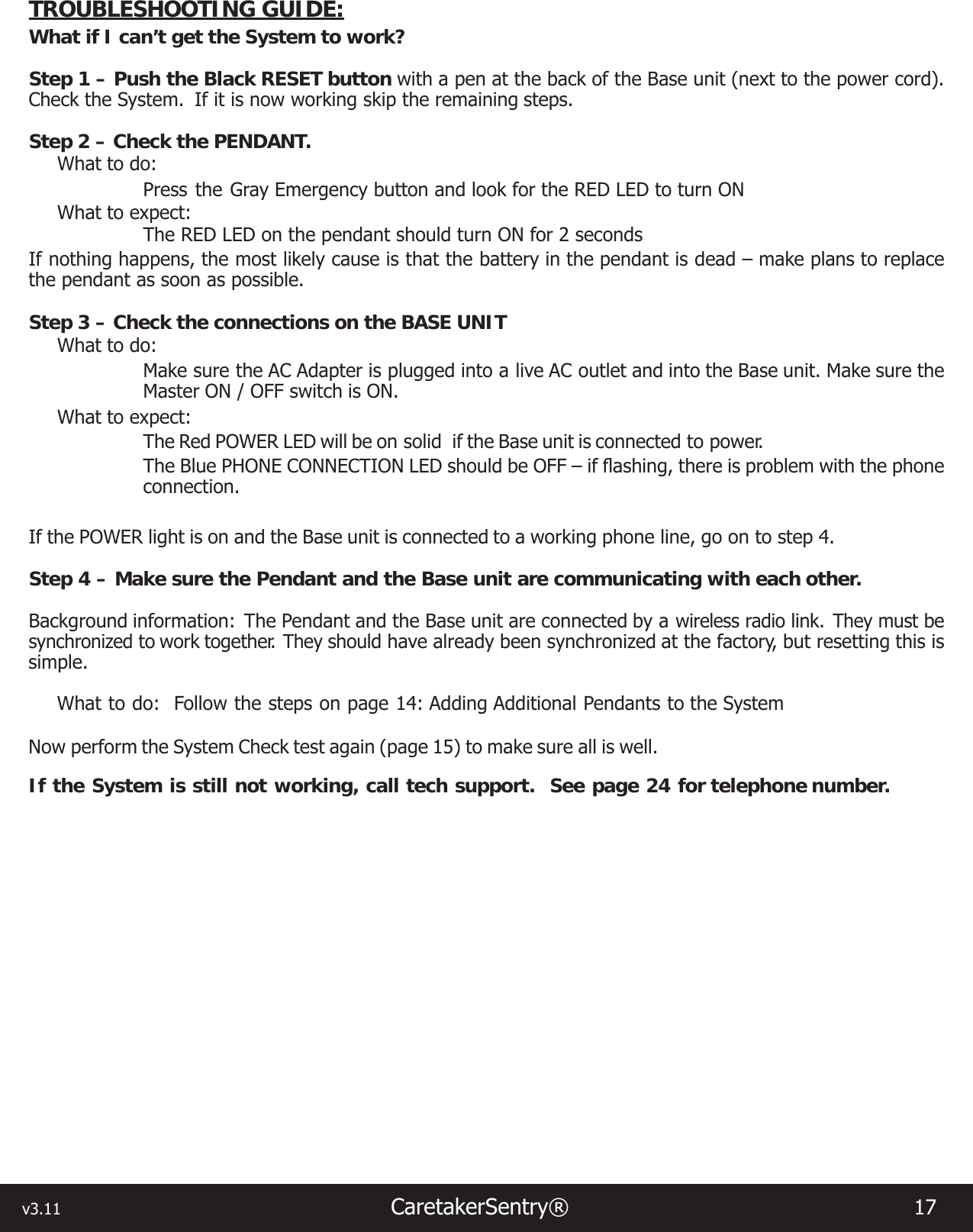
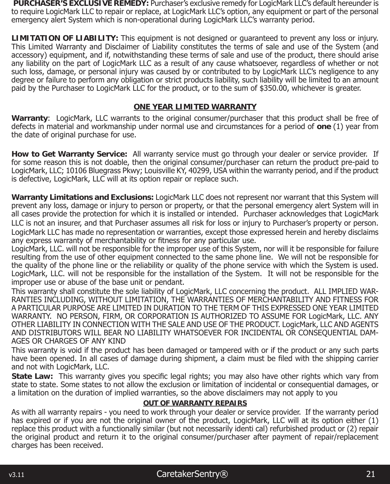
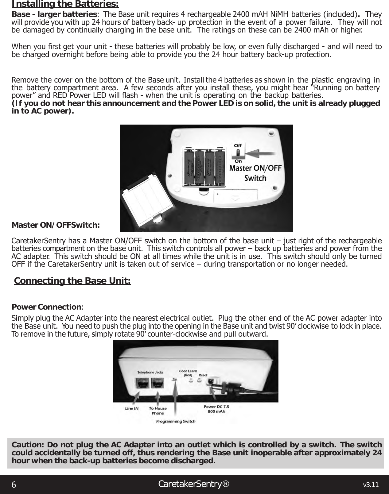
![12CaretakerSentry® v3.11DLE-200 test box. NEVER LEAVE THE UNIT IN THIS MODE FOR NORMAL OPERATION.1. Enter (Passcode) – XXXX then “**” (Default is 1234) [Voice prompt – Option Mode]2. Enter – 4 [Voice prompt – DEMO Tradeshow Mode],1 for YES 3 for NO– FACTORY SETTING3. Enter either 1 or 3 [Voice prompt 1 – YES] [Voice prompt 3 – NO]4. Enter “#” (to exit programming mode) [Voice prompt – Programming complete]5. Slide Programming Switch to “Normal Operation” [Voice prompt – “Emergency Call Mode”]Option #6 -- Automatic Call-Back Feature - This feature allows the unit to call a central station, send the Emergency Event information, hang-up and then automatically answer a return call back. After the base connects with central station, transmits the Personal Emergency and account info and receives the Kiss-Off tone, the base hangs up but keeps the communication link active between the pendant/EWC and itself. .It will then answer the next incoming call and the Customer will speak with the central station with no indication that a callback has occurred.1. Enter (Passcode) – XXXX then “**” (Default is 1234)[Voice prompt – Option Mode]2. Enter – 6[Voice prompt – Automatic Call-back Mode],1 for YES3 for NO– FACTORY SETTING3. Enter either 1 or 3[Voice prompt 1 – YES] [Voice prompt 3 – NO]4. Enter “#” (to exit programming mode)[Voice prompt – Programming complete]5. Slide Programming Switch to “Normal Operation”[Voice prompt – “Emergency Call Mode”]Option #7 – Send Restore Message - These are messages that are automatically sent to the central station to report the AC Power or the communication (RF or battery) problem with the Pendant has been restored or corrected.1. Enter (Passcode) – XXXX then “**” (Default is 1234) [Voice prompt – Option Mode]2. Enter – 7[Voice prompt – Send restore code to call center,1 for YES – 3 for NO]3. Enter either 1 or 3[Voice prompt 1 – YES][Voice prompt 2 – NO] – FACTORY SETTING4. Enter # (to exit programming mode)[Voice prompt – Programming complete]5. Slide Programming Switch to Normal Operation[Voice prompt – “Emergency Call Mode”]Option #8 - Periodic Test Interval (for automatic check-in with central station)1. Enter (Passcode) – XXXX then “**” (Default is 1234) [Voice prompt – Option Mode]2. Enter – 8](https://usermanual.wiki/LogicMark/CS40914.manual/User-Guide-2168108-Page-12.png)
![v3.11 CaretakerSentry® 13 [Voice prompt – Periodic test interval,1 for 1 day,2 for 7 days,FACTORY SETTING 3 for 30 days]3. Enter 1, 2 or 3[Voice prompt 1 – Every day] [Voice prompt 2 – Every 7 days] [Voice prompt 3 – Every 30 days]4. Enter “#” (to exit programming mode)[Voice prompt – Programming complete]5. Slide Programming Switch to “Normal Operation” [Voice prompt – “Emergency Call Mode”]Option #9 – Reset To Factory Settings1. Enter (Passcode) – XXXX then “**” (Default is 1234) [Voice prompt – Option Mode]2. Enter 9 [Voice prompt – Reset to factory settings,1 for YES – 3 for NO]3. Enter either 1 or 3[Voice prompt 1 – YES] [Voice prompt 3 – NO]4. Enter “#” (to exit programming mode)[Voice prompt – Programming complete]5. Slide Programming Switch to “Normal Operation” [Voice prompt – “Emergency Call Mode”]Note: The telephone numbers are erased, so if the Emergency button is pushed, you will hear the dial tone and then “Hanging Up”REMOTELY PROGRAMMING THE System:The System can be remotely programmed over a telephone line in one of two ways – Standard and Unaided Remote Programming.Standard Method: 1. Simply call the number of the residence where the System is connected. 2. Have the user slide the switch at the back of the base unit to “Programming Mode”. 3. Then, proceed to program the System as needed with the touch-tones of the phone on which you are calling from. 4. Have them slide the switch back to Normal Operation when done. Unaided Remote Programming:1. The dealer calls the customers phone number that the CaretakerSentry is installed on.2. The dealer allows the phone to ring 1 ring cycle - (equivalent to 1 ring back tone - about 6 seconds of ringing).3. The dealer then hangs up.4. The dealer waits 10 seconds and dials the customer phone number again. The CaretakerSentry sees this second call within a 30 second period and immediately answers the phon.• The CaretakerSentry will only start this 30 second timer - waiting for a second call to ring the phone ONLY if the phone only rings 1 time. If the phone rings more than 1 time, the CaretakerSentry unit will not start the timer and will NOT wait for the second call - feature is canceled and reset.5. As soon as the CaretakerSentry answers the call, [voice prompt – programming mode] is played.6. The dealer enters the 4 digit passcode and then CaretakerSentry enters programming mode (unit will program normally).](https://usermanual.wiki/LogicMark/CS40914.manual/User-Guide-2168108-Page-13.png)