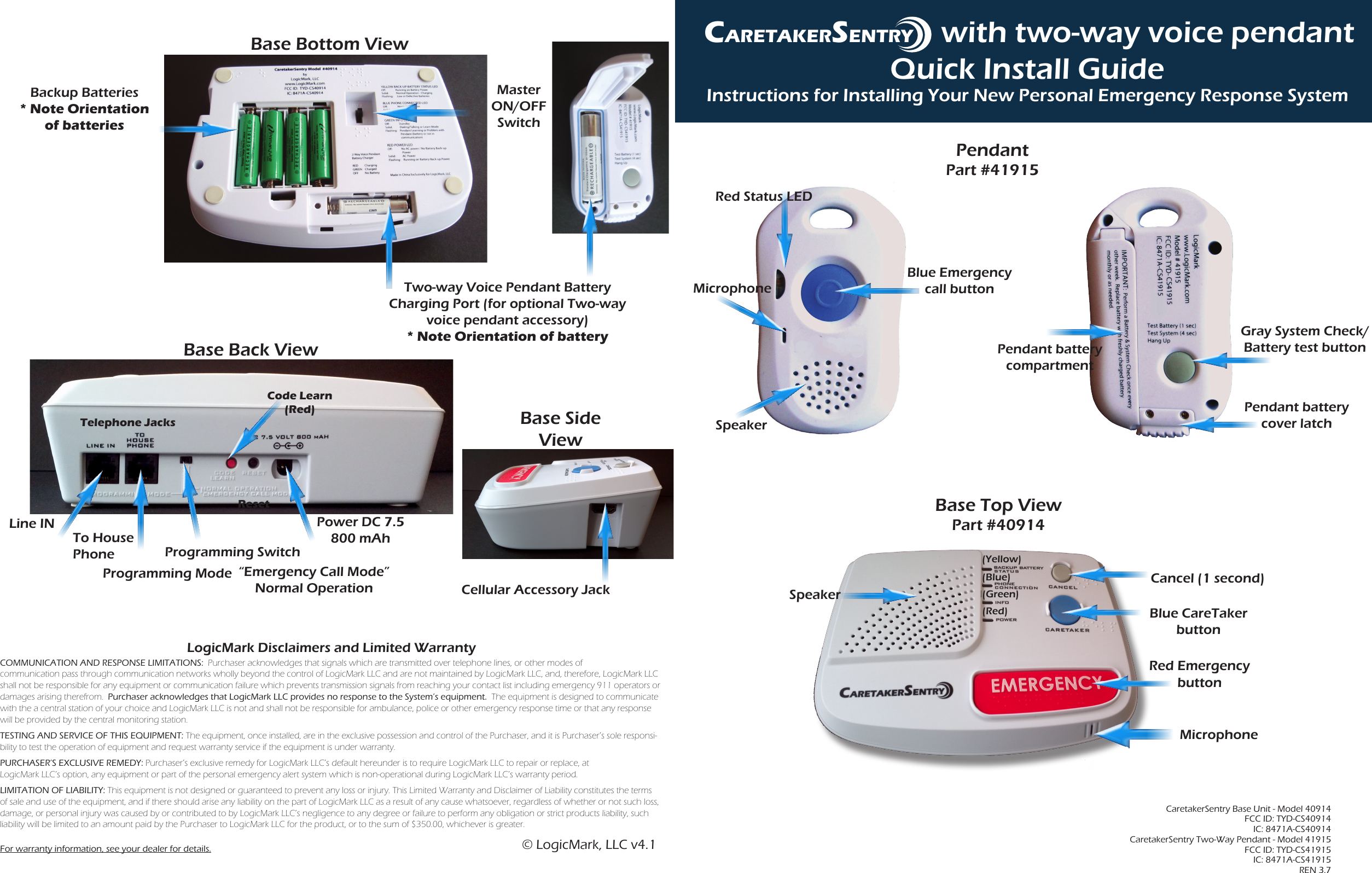
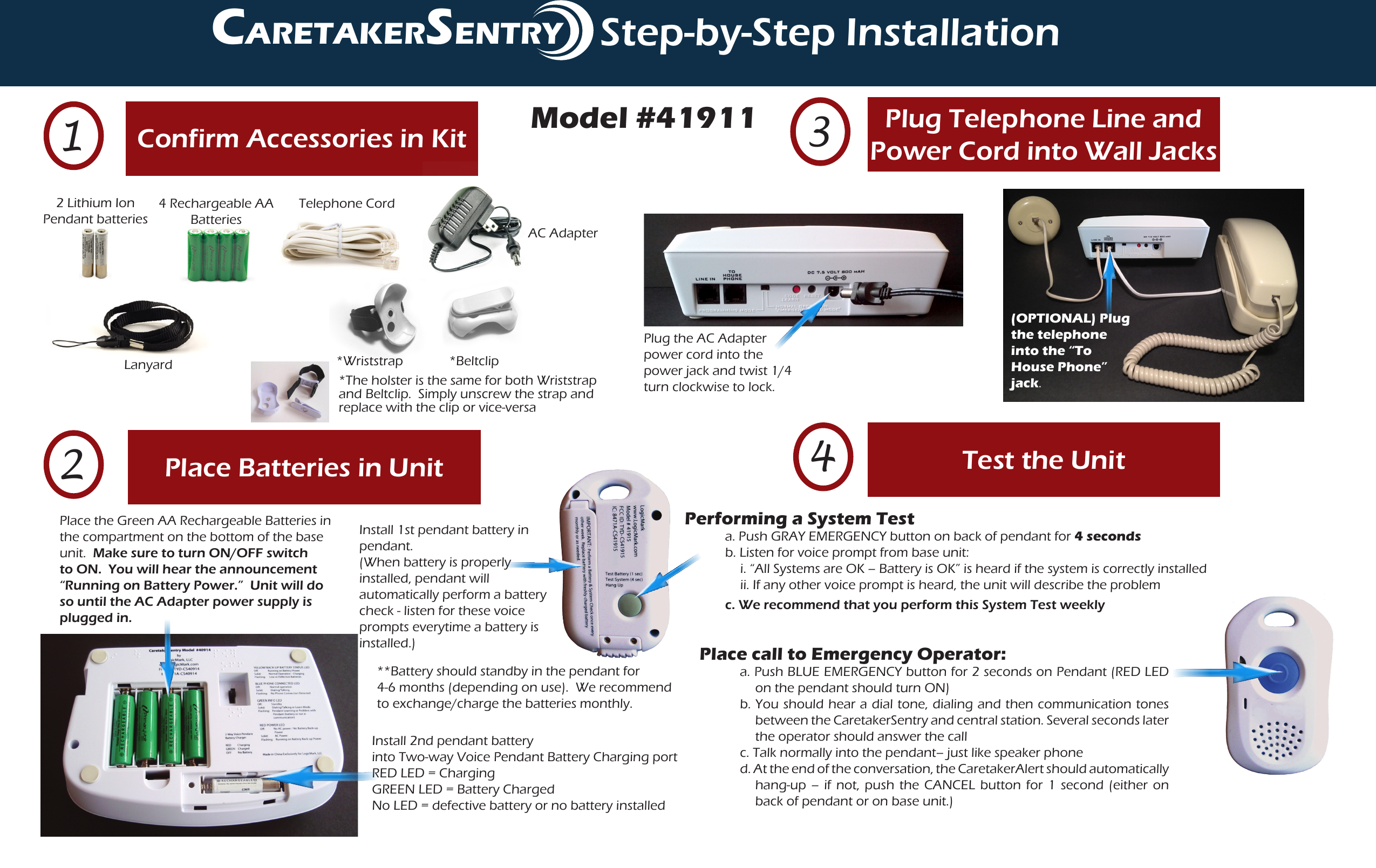
LogicMark CS40914 PERS-Personal Emergency Response System User Manual 15 40914 UserMan

LogicMark, LLC PERS-Personal Emergency Response System 15 40914 UserMan

Contents

15_40914 UserMan

CaretakerSentry with two-way voice pendant Quick Install GuideInstructions for Installing Your New Personal Emergency Response SystemLogicMark Disclaimers and Limited WarrantyCOMMUNICATION AND RESPONSE LIMITATIONS:  Purchaser acknowledges that signals which are transmitted over telephone lines, or other modes of  communication pass through communication networks wholly beyond the control of LogicMark LLC and are not maintained by LogicMark LLC, and, therefore, LogicMark LLC shall not be responsible for any equipment or communication failure which prevents transmission signals from reaching your contact list including emergency 911 operators or damages arising therefrom.  Purchaser acknowledges that LogicMark LLC provides no response to the System’s equipment.  The equipment is designed to communicate with the a central station of your choice and LogicMark LLC is not and shall not be responsible for ambulance, police or other emergency response time or that any response will be provided by the central monitoring station.TESTING AND SERVICE OF THIS EQUIPMENT: The equipment, once installed, are in the exclusive possession and control of the Purchaser, and it is Purchaser’s sole responsi-bility to test the operation of equipment and request warranty service if the equipment is under warranty.PURCHASER’S EXCLUSIVE REMEDY: Purchaser’s exclusive remedy for LogicMark LLC’s default hereunder is to require LogicMark LLC to repair or replace, at  LogicMark LLC’s option, any equipment or part of the personal emergency alert system which is non-operational during LogicMark LLC’s warranty period.LIMITATION OF LIABILITY: This equipment is not designed or guaranteed to prevent any loss or injury. This Limited Warranty and Disclaimer of Liability constitutes the terms of sale and use of the equipment, and if there should arise any liability on the part of LogicMark LLC as a result of any cause whatsoever, regardless of whether or not such loss, damage, or personal injury was caused by or contributed to by LogicMark LLC’s negligence to any degree or failure to perform any obligation or strict products liability, such liability will be limited to an amount paid by the Purchaser to LogicMark LLC for the product, or to the sum of $350.00, whichever is greater.For warranty information, see your dealer for details.CaretakerSentry Base Unit - Model 40914 FCC ID: TYD-CS40914 IC: 8471A-CS40914 CaretakerSentry Two-Way Pendant - Model 41915 FCC ID: TYD-CS41915 IC: 8471A-CS41915REN 3.7Base Back ViewTelephone JacksLine INTo House Phone  Programming SwitchProgramming Mode “Emergency Call Mode”Normal OperationResetPower DC 7.5 800 mAhCode Learn(Red)Cellular Accessory JackBase Side ViewCARETAKERSENTRY© LogicMark, LLC v4.1PendantPart #41915Gray System Check/Battery test buttonRed Status LEDMicrophoneBase Top ViewPart #40914Red Emergency button (Blue)I(Green)(Red) Blue CareTaker buttonMicrophone(Yellow)SpeakerCancel (1 second)Blue Emergency call buttonPendant battery cover latchPendant battery compartmentSpeakerBackup Batteries* Note Orientation of batteriesBase Bottom ViewMaster ON/OFF SwitchTwo-way Voice Pendant Battery  Charging Port (for optional Two-way voice pendant accessory)* Note Orientation of battery
Plug Telephone Line and Power Cord into Wall Jacks3CaretakerSentrStep-by-Step InstallationPlace the Green AA Rechargeable Batteries in the compartment on the bottom of the base unit.  Make sure to turn ON/OFF switch to ON.  You will hear the announcement “Running on Battery Power.”  Unit will do so until the AC Adapter power supply is plugged in.Place Batteries in Unit2Confirm Accessories in Kit1Plug the AC Adapter power cord into the power jack and twist 1/4 turn clockwise to lock.4 Rechargeable AABatteriesTelephone CordAC AdapterLanyardTest the Unit4Place call to Emergency Operator:a. Push BLUE EMERGENCY button for 2 seconds on Pendant (RED LED on the pendant should turn ON)b. You should hear a dial tone, dialing and then communication tones between the CaretakerSentry and central station. Several seconds later the operator should answer the callc. Talk normally into the pendant– just like speaker phoned. At the end of the conversation, the CaretakerAlert should automatically hang-up – if not, push the CANCEL button for 1 second (either on back of pendant or on base unit.)Performing a System Test   a. Push GRAY EMERGENCY button on back of pendant for 4 seconds      b. Listen for voice prompt from base unit:i. “All Systems are OK – Battery is OK” is heard if the system is correctly installedii. If any other voice prompt is heard, the unit will describe the problem  c. We recommend that you perform this System Test weeklyModel #41911(OPTIONAL) Plug the telephone into the “To House Phone” jack.Install 2nd pendant batteryinto Two-way Voice Pendant Battery Charging portRED LED = ChargingGREEN LED = Battery ChargedNo LED = defective battery or no battery installed**Battery should standby in the pendant for 4-6 months (depending on use).  We recommend to exchange/charge the batteries monthly.Install 1st pendant battery in pendant.(When battery is properly installed, pendant will automatically perform a battery check - listen for these voice prompts everytime a battery is installed.)2 Lithium IonPendant batteries*Beltclip*Wriststrap*The holster is the same for both Wriststrap and Beltclip.  Simply unscrew the strap and replace with the clip or vice-versa CARETAKERSENTRY

Navigation menu