Long E Technology TA27TA30 Remote Control User Manual TA30 manual
Long-E Technology (Shenzhen) Co., Ltd. Remote Control TA30 manual
User Manual

GS-500A W/O ANTI HIJACKING FUNCTIONAL MANUAL Page 1 of 5
TA30 ANTI HIJACKING FUNCTIONAL MANUAL
Button Press function Conditions
0.5 seconds Arm/door lock
Lock the door
Stop alarm sounding
Alarm is disarmed
In valet mode
Alarm sounding
1
2 seconds panic Anytime
0.5 seconds Disarm/door unlock
Unlock doors
Stop alarm sounding and disarm
Alarm is being armed
In valet mode
Alarm sounding
2
2 seconds Auxilary 1 output (trunk release) Anytime
1Æ1 Æ Within 5 seconds Arm bypassing shock sensor Alarm is disarmed
1+2 + 2 seconds Auxilary 2 output Anytime
2Æ2Æ Within 5 seconds Passenger unlock Alarm is being armed
3 2 seconds Car finder Anytime
3Æ1 Æ Within 10 seconds Silent arming/door lock Alarm is disarmed
3Æ2Æ Within 10 seconds Silent disarming / door unlock Alarm is being armed
4 0.5 seconds Shift for 2 car operation Anytime
The system is supplied with two 4-buttons remote transmitters used to control system operations.
Button 1 arms the system and when held for 2 seconds, activates the system’s panic feature. Button 1 also locks the doors when
the system is in valet mode.
Button 2 disarms the system. Pressing button 2 again operates the passenger unlock feature (if installed). Button 2 also unlocks
the doors when the system is in valet mode. To hold the button 2 for 2 seconds shall activate the auxiliary channel output 1 for
trunk release function; This output will remain on for as long as the button is pressed.
Button 3 activates the silent operation for the arming and disarming.
Press button 3 then button 1 arms the system silently.
Press button 3 then button 2 disarms the system silently.
Press button 3 for 2 seconds activates the vehicle locator feature which flashes the parking lights and chirps the siren 5 times.
This feature is useful to help locate the vehicle in a crowded parking lot.
Button 1+2 activates the auxiliary 2 output. This output will remain on for as long as the button is pressed.
Button 4 is the page shift button. The page shift button will change the function of buttons 1 through 4 each time it is pressed,
allowing access to additional features or multiple car operation. Each time the shift button is pressed, the led on the transmitter
will illuminate and the transmitter functions will shift to the next page, allowing access to another set of features. Once shifted to
another page(there are 4 pages total), the transmitter will remain on that page for 10 seconds or until a button is pressed, then
return to page 1. each time a transmitter button is pressed and held, the led will flash a number of times to indicate from which
page it is transmitting. Under normally operation, only pages 1 and 2 are used. Page 3 and 4 are usually used for two car
operation.
1. ADDING/REPLACING TRANSMITTERS (Code learning)
To replace lost or stolen transmitters or to add additional transmitters into the system, have all desired transmitters ready and
follow the steps below.
NOTE: Up to 4 transmitters can be programmed to operate the system. To erase any previously stored transmitter codes, be sure
to program all 4 transmitter memory location.
To program the transmitter(s):
1) Turn on the ignition key on, off, on, off, and back on.
The sire will chirp 3 times.
2) Press and hold the override switch for 3 seconds.
The siren will chirp 5 times. The led will illuminate.
3) Press any button on the first transmitter.
The siren will chirp once.
4) Press any button on the first transmitter again.
The siren will chirp twice to indicate it has learned the code.
5) Repeat steps 3 and 4 for each transmitter (up to 4).
6) Turn off the ignition key.
***TWO CAR OPERATION
If two vehicles are equipped with this system, for convenience both can be operated using the same remote transmitter. If all four
transmitters are to be used with both cars, program transmitters A and B into the first vehicle in the manner described above.
Program transmitters C and D by pressing the shift button twice before performing steps 3 and 4 above.
When finished programming the first vehicle, program transmitters C and D into the second vehicle as normal, then program
transmitters A and B by pressing the shift button twice before performing steps 3 and 4 above.
When programmed in this manner, the driver of the first car can also operate the second vehicle by pressing the shift button
twice and the desired function button.
2. REMOTE ARMING
The system monitors independent areas (zones) while armed: doors, hood/trunk, shock sensor and optional sensor input.
To arm the system:
1) Turn off the ignition.
2) Press button 1.
The siren will chirp once. The doors will lock. The parking lights will flash once. The led will turn on red, to indicate the
starter defeat is activate.
3) 5 second after arming:
The led will start blinking to indicate that the doors and hood/trunk inputs are being monitored. (see function selection #11 for
door input monitoring on the delay time)
z During arming, if the system detects a bad sensor or an open zone, the system will chirp 4 additional times and ignore that
input, but keep all other areas protected.
Once armed, the alarm will trigger when any of the following occurs:
The doors are opened. The hood or trunk is opened. The shock senor detects an impact to the vehicle. The optional sensor is
disturbed.
When the alarm triggers, the siren will sound, the horn will honk, and the parking lights will flash, the led will flash rapidly. The
system alarm will last for 30 seconds.
In the event the alarm is triggered and remains triggered continuously by the same sensor or input during a single arming cycle,
that sensor or input will be automatically bypassed until the next time the system is armed.
If the shock sensor detects a light impact to the vehicle, or the optional sensor’s warn-away zone is disturbed, the siren will chirp
5 times as a warning indication. If the heavy impact is detected, the siren shall sound continously with flashing the parking light
at the same time.
3. REMOTE DISARMING
To disarm the system:
Press button 2.
The siren will chirp twice. The doors will unlock. The parking lights will flash twice. The dome light will turn on. The led will
turn off.
z During disarming, if the system is triggered while away from the vehicle, the siren will chirp 3 times, the parking lights will
flash 3 times, and the led will flash to indicate triggered zone. See tamper alert for zone listing.
4. TAMPER ALERT
If the system is triggered while away, the LED will flash to indicate which zone triggered the system after disarming and turning
on the ignition. The LED indication will repeat 1 minute. LED Flashes:
1 flash=optional sensor
2 flashes=shock sensor
3 flashes=not used
4 flashes=door
5 flashes=trunk
10 flashes=main power interrupt or system was reset
example: flash-flash-pause-flash-flash-pause=shock sensor
5. SILENT ARMING/DISARMING
The system can be programmed to operate without Arm and Disarm chirp indications. When programmed for full-time silent
operation, the siren will sound when the system is triggered. And when the auto rearming and passive arming are working, the
siren shall chirp once too when the system gets armed.
The system is also capable of temporary silent operation if desired. Pressing the button 3 before Arming or Disarming the system
will bypass the chirp confirmations and allow one-time silent operation.
Note: The open zone warning chirps will not be bypassed when system is Armed
6. PASSIVE ARMING
When programmed for the optional Passive Arming feature, the system arms itself automatically, each time the ignition is turned
off and all of the doors, hood, and trunk are closed. (select programming #2 for passive arming or passive arming w/countdown)
To start the Passive Arming Process:
1) Turn off the ignition.*
2) Open the door and exit the vehicle.
Once all doors are closed and the dome light is off, the LED will begin flashing rapidly.
3) After 30 seconds:
The siren will chirp once. (no matter whether #14 arming chirp is programmed silent or normal, it always chirps once when

GS-500A W/O ANTI HIJACKING FUNCTIONAL MANUAL Page 2 of 5
arming). The parking lights will flash. The doors will lock.** The status LED will begin flashing.
4) The system is now armed.
*The ignition must have been on for at least 3 seconds or the Passive Arming sequence will be disabled.
**If the passive locking feature is selected.
To temporarily disable Passive Arming, turn on the ignition then turn off within 3 seconds. The siren will chip once indicating
the system will not passively arm until the ignition is cycled again.
If the Passive Arming with Countdown feature is programmed, the siren will chirp every 2 seconds until the system passively
arms.
Note: If the Passive Arming feature is enabled, the Automatic Rearming feature will also be enabled even if it was not
already programmed.
7. PANIC MODE
In the event of an emergency the transmitter’s remote Panic feature can be used to instantly trigger the alarm.
To activate the Panic Mode:
1) When ACC off, press and hold Button 1 for 2 seconds. The alarm will sound for 30 seconds. The parking lights will flash.
The doors will lock then unlock* allowing access to the vehicle.
2) Press Button 2 to stop Panic Mode.
*If the ignition is on when the panic feature is activated, the doors will lock for personal safety.
8. EMERGENCY OVERRIDE
If the transmitter becomes lost or inoperable, the system can still be disarmed using the following procedure. Before beginning
this procedure be sure to have the ignition key ready and know the location of the override switch.
To Emergency Override the system:
1) Unlock the door using the key.
2) Enter the vehicle. The system will trigger and the siren will sound.
3) Turn ignition key on.
4) Press and hold the override switch for 5 seconds. The system will disarm.
5) The vehicle will now be able to start.
9. Optional Coded Emergency Override
As an extra measure of security, the system is equipped with an optional Coded Emergency Override feature. Once an
Emergency Override Coded is chosen and programmed during installation, the system can no longer be disarmed using the
standard Override procedure.
To Emergency Override the system using the Code:
1) Follow steps 1-3 above.
2) Press the override switch a number of times equal to the Disarm code, and continue holding for 5 seconds on the last press.
the system will disarm . If the code is entered incorrectly, turn off the ignition and begin again.
To set the emergency override code:
1) Turn on ignition.
2) Within 5 seconds, press the valet switch 5 times.
The siren will provide one long chirp, indicating that you have entered programming.
3) Press the valet switch 3 times.
The siren will chirp each time the valet switch is pressed.
4) Within 5 seconds, press button 3 on the transmitter.
The siren will chirp 3 times.
5) Press the valet switch the number of time equal to the desired code(from 1-15). If there is no press on the valet switch at this
stage but turn ignition off and arm the system, then it returns to the factory default to override the system, and no code is
required any more in emergency disarming.
6) Turn off the ignition then arm the system.
7) Disarm the system using the new override code to permanently store the new code.
NOTE: if the code set procedure is not properly performed, turn off the ignition and begin again. The override code will not be
permanently stored until the code is used to disarm the system.
10. AUTOMATIC REARMING
The automatic Rearming feature is designed to protect the vehicle in the event the system is accidentally disarmed. With the
Automatic Rearming feature enabled, the alarm will automatically rearm 30 seconds after disarming. If the optional Passive
Door lock feature is enabled, the doors will also lock when the system rearms.
The Automatic Rearming feature will be temporarily bypassed until the next arming cycle if the ignition is turned on or the
door/trunk/hood zone is opened.
11. VALET MODE
The valet mode temporarily disables the security system so the vehicle may be operated by a mechanic or parking attendant.
To activate or deactivate the valet mode:
1) Turn on the ignition.
2) Press and hold the override switch for 5 seconds.
The siren will chirp once to confirm the valet mode is on.
The siren will chirp twice to confirm the valet mode is off.
3) Turn off the ignition.
While in valet mode the remote transmitters will continue to lock and unlock the doors, and operate the optional auxiliary
functions.
12. IGNITION CONTROLLED DOOR LOCKS
For added safety, the Ignition Door locking feature. Allows vehicles equipped with power door lock systems to automatically
lock the doors when the ignition is turned on. When igntion off, the door lock shall unlock automatically. The ignition locking
feature is disabled to protect against locking the keys inside the vehicle. See function selection #4.
13. DOME LIGHT ACTIVATION
If the optional Dome light Activation feature is installed, the dome light will turn on when the system is disarmed using the
Remote Transmitter. The dome light will remain on for 30 seconds or until the ignition is turned on.
14. AUXILIARY FUNCTION OUTPUTS
The system is equipped with 2 Auxiliary Outputs allowing the convenience features of the system to be further expanded. These
outputs can be used to add a number of optional features such as: power trunk release, remote engine start, power window
activation, power sunroof control, and more.
15. REMOTE SENSOR DISABLE
When parking the vehicle in areas susceptible to unwanted disturbance from animals or strong weather conditions that could
cause the sensors to trigger, the sensor inputs can be temporarily bypassed using the Remote Transmitter, preventing possible
false alarms.
To disable the sensor inputs:
1) Arm the system normally.
2) Within 5 seconds of Arming the system, press the Arm button again. The siren will chirp 5 times and the parking lights will
flash 5 times to indicate the sensors are disabled. The sensors will remain disabled until the next arming cycle.
16. Entering System Programming
To enter System Programming:
3) Turn on ignition.
4) Within 5 seconds, press the valet switch 5 times.
The siren will provide one long chirp, indicating that you have entered Programming.
5) Press the valet switch the number times equal to the System Option you want to change.
The siren will chirp each time the valet switch is pressed.
6) Within 5 seconds, press the transmitter button corresponding to the desired operating mode for that System Option.
The siren will chirp to indicate the setting.
1 chirp = Button 1
2 chirps = Button 2
3 chirps = Button 3
7) When you are finished, turn off the ignition to save the changes.
17. Default Reset
Following this procedure will set all Programmable System Options to factory default settings.
1) Enter System programming.
2) press Transmitter Button 3.
The siren will chirp 4 times indicating that the reset signal was received.
All programmable System Options are now set to factory default settings.
The Valet Mode is off.
The Disarm Code is 1.
3) Turn off ignition.
PROGRAMMABLE SYSTEM OPTIONS
Branch Feature Button1(default) Button2 Button3
1.Horn Chirps W/ Arm&Disarm Normal Horn Chirps Horn Chirps w/warn
2.Arm Mode Manual Arming Passive Arming Passive w/Countdown
3.Passive Door Locking Disabled Enabled Set Override Code
4.Ignition Controlled Locks On Off Lock Only
5. Channel 2 mode 0.5s pulse 10s latched
6. Channel 3 mode 0.5s pulse 10s latched
7. Door lock Pulse Length 1 Second 3 seconds 0.1 second
10.Ignition Armed Mode Disabled Enabled
11.Door Input Monitoring 5 Seconds 10 Seconds 60 Seconds
12.Auto Rearming Disabled Enabled
13.Door Unlock Pulse Single Double
14.Arming Chirps Normal Silent
15.Extended Parking Lights Off On
16.Disarm Chirp Normal Silent

GS-500A W/O ANTI HIJACKING FUNCTIONAL MANUAL Page 3 of 5
The following is a description of the programming options. Some program branches control more than one option, and may
require accessing a particular branch number twice in order to program all desired features.
1. Horn Chirps With Arm&Disarm. Selects one of three modes: Normal, Horn Chirps, and Horn Chirps w/warn.
Normal: When selected, the horn will honk only when the alarm is triggered.
Horn Chirps:When selected, the horn will provide arm/disarm trigger indications, allowing the siren installation to be skipped.
Horn chirps with warn: When selected, the horn will provide arm/disarm, trigger, and warn-away indications.
2. Arm Mode. Selects one of three modes: Manual Arming or Passive Arming, and passive arming w/Countdown. With the
passive arming w/Countdown mode selected, the siren will chirp every 2 seconds while counting down until the system
passively arms. Note: If Auto Rearming is selected, the siren will also chirp during Auto Rearm countdown.
3. Passive Door Locking/Override Code Set. This dual program branch sets passive locking and programs the optional
Emergency Override Code.
Passive Door Locking: Selects whether or not the system will automatically lock the doors when the passive arming funtions.
Override Code Set: Changes the Emergency Override Code for a higher level of security.
4. Ignition Controlled Locks. Selects whether or not the system will lock and unlock the doors with the ignition. If Lock Only is
selected, the doors will not automatically unlock when the ignition is turned off.
5. Channel 2 mode: this has provided the 3 options of pulse time to activate the connected module such as the trunk release
module etc. Select the time according to the request of the function module. Latched is the continous output when the button
is pressed.
6. Channel 3 mode: this has provided the 3 options of pulse time to activate the connected module such as the trunk release
module etc. Select the time according to the request of the function module. Latched is the continous output when the button
is pressed.
7. Door Lock Pulse Length. Selects between a 1-second, a 3-second and a 0.1 second output for door locking and unlocking.
Program to 3 seconds for vehicles equipped with vacuum door locking systems.
10. Ignition Armed Mode. When enabled, the security system may also be manually armed and disarmed using the
transmitter, while the ignition is on.
11. Door Input Monitoring. Selects whether the system begins monitoring the door inputs after 5 seconds, 10 seconds or 60
seconds. For vehicles with interior lights that remain on for an extended period of time after the doors are closed, set for
60 seconds.
12. Auto Rearming Mode. When selected, the system will automatically re-arm 30 seconds after it is disarmed if the doors
have not been opened.
13. Door Unlock Pulse. Selects between one pulse or two pulse operation for the door unlock output. Vehicles that require
two pulses on the proper wire to unlock the doors can be interfaced directly without the use of relays or any additional
circuitry by programming the system for double unlock pulse.
14. Arming Chirps. Selects between normal and silent operation.
15. Extended Parking Lights. When selected, the parking lights will remain on for 30 seconds after disarming the system.
16. Disarm Chirp: To decide whether have disarm chirp indication.
BATTERY REPLACEMENT
Your Remote Transmitter uses a 12 volt alkaline battery(type 23A),which will require replacement in time. Depending on the
amount of use, the battery may last up to six months or more before it needs replacement.
When the battery needs replacing, the system’s operating range will decrease or the transmitter LED may not be as bright.
In order to change the battery, first remove 2 screws from the back of the transmitter and separate the top and bottom halves of
the case.
While replacing the battery make sure that the positive and negative terminals are positioned correctly, then carefully reassemble
the transmitter case.
SYSTEM INSTALLATION
1. Thoroughly read and become familiar with the installation instructions before beginning the installation.
2. Review system contents: Main Unit、Two 4-Button Remote Transmitters、Siren、 Shock Sensor、18-Pin main harness、4-Pin
shock sensor harness、LED harness、Valet Switch harness.
3. Verify with the owner, the mounting locations for all visible components, including the LED and override switch.
4. Verify with the owner, the optional features of the system and the features that must be programmed during installation.
5. Inspect and perform a function test of all vehicle systems before and after the installation.
6. Always use a Volt/Ohm meter for testing vehicle circuits. Never use a test light.
7. Always look before drilling any holes or mounting self-tapping screws. Be sure fuel lines and exterior wiring looms are clear
as they are often close to the chassis and difficult to see.
8. Protect all wires running from the engine compartment to the interior of the vehicle by covering with electrical tape and split
loom tubing. Be sure to use a grommet when routing wires through the firewall.
9. Properly fuse any additional accessories such as window modules, door lock actuators, etc, making sure to power them
separate from the alarm module. This will ensure the functionality of the security system in the event of an accessory failure.
MOUNTING THE CONTROL UNIT
The control nit must only be mounted in the interior of the vehicle. Do not mount the main unit in the engine compartment.
Choose a mounting location that will not be easily accessible to a thief, and will not interfere with the operation of any
vehicle components such as foot pedals, steering column, air vents, seat rails, etc.
Do not mount the control unit until after setting the internal jumpers and performing a compete operation check of the system.
After installation is complete and performance on the bottom of the unit.
MOUNTING THE SIREN
Choose a siren mounting location that is away from beat sources such as exhaust manifolds, and where it cannot be easily
accessed from underneath the vehicle. Be sure to face the siren downward to prevent the collection of water in the siren’s
housing.
Always route all wires from the engine compartment into the interior of the vehicle through a proper grommet.
MOUNTING THE SHOCK SENSOR
Choose a suitable interior mounting location for the shock sensor that provides ample coverage of the vehicle. Keep the
sensor away from the vehicle’s ECM or other sources of electrical interference. Suggested mounting locating include air
conditioning ducts, dashboard braces, or center console supports.
During proper operation, the shock sensor will detect impacts to the vehicle only and will not usually be triggered by slow
rocking movements of the vehicle like those caused by wind.
GS-500A W/O ANTI HIJACKING FUNCTIONAL MANUAL Page 4 of 5
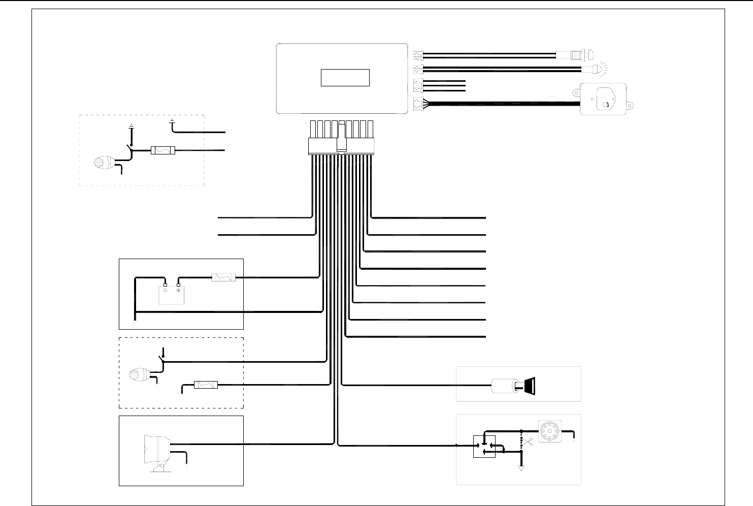
PARKING LIGHT
15A
FUSE
GND
(-)
DOOR TRIGGER INPUT
SIREN
LED INDICATOR
BATTERY
YELLOW
ORANGE
BROWN
WHITE
BLACK
RED
IGNITION KILL RELAY
12V START INPUT
START MOTOR
87a
30
86
CUT
RED/WHITE
85
RED
(+)
DOOR TRIGGER INPUT
GS-500A
KEY ON
10A
FUSE WHITE
WHITE
(-)
LOCK OUTPUT
(-)
UNLOCK OUTPUT
(-)
CHANNEL 2 OUTPUT
(-)
CHANNEL 3 OUTPUT
(-)
DOME LIGHT OUTPUT
(-)
PASSENGER UNLOCK OUTPUT
(-)
HORN OUTPUT
(-)
HOOD OR TRUNK TRIGGER INPUT
BLUE
/
WHITE
BLUE
BROWN/WHITE
BLACK/WHITE
WHITE/BLUE
WHITE/RED
BLUE/BLACK
GREEN/BLACK
GREEN
VIOLET
SHOCK SENSOR
AUXILIARY
SENSOR CONNECTOR
VALET S.W
+12V
SHOCK SENSOR
PARKING LIGHT SWITCH
+12V
PARKING LIGHT
PARKING LIGHT SWITCH
10A
FUSE
+12V
WHITE
WHITE

GS-500A W/O ANTI HIJACKING FUNCTIONAL MANUAL Page 5 of 5
Warning:
This device complies with part 15 of the FCC Rules. Operation is subject to
the following two conditions: (1) This device may not cause harmful interference,
and (2) this device must accept any interference received, including interference
that may cause undesired operation.
Changes or modifications not expressly approved by the party responsible for
compliance could void the user's authority to operate the equipment.