Long Range Solutions TX9601 Paging transmitter with keypad and display User Manual Layout 1
Long Range Systems, LLC Paging transmitter with keypad and display Layout 1
User Manual
SERVER
V1
V2 V3
1
2
3
4
5
6
7
8
9
10
11
12
13
14
15
16
PROG
PGR
CLR
ENT
www.pager
.net
Usage, Installation, Warranty and Service Information
Long Range Systems, LLC
4550 Excel Parkway, Suite 200
Addison, TX 75001
800.437.4996 •www.pager.net
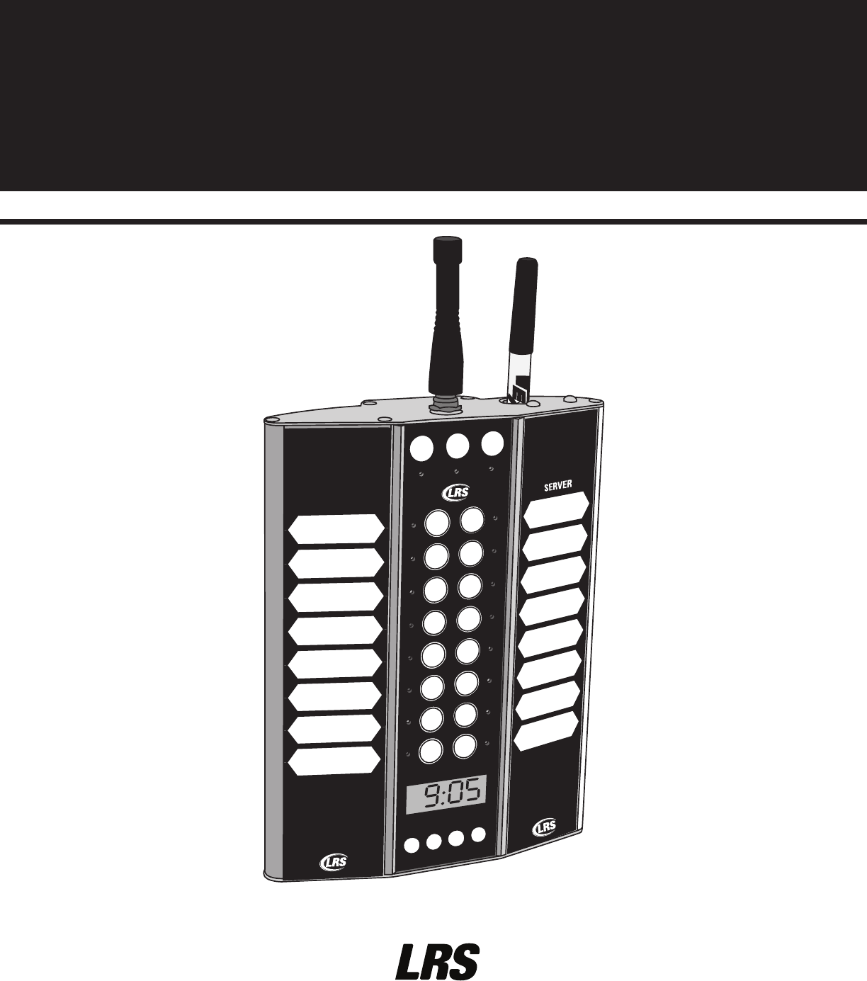
T9601
Paging System Transmitter
USER MANUAL

Warranty
Long Range Systems, LLC permits a one-year manufacturer’s warranty following the original consumer purchase date of any LRS sys-
tem. Any individual components or products purchased will receive a 30-day manufacture warranty. This warranty covers any defects
due to faulty material or workmanship, but does not include damage to the product resulting from accident, misuse or improper elec-
trical connection. If the product or system should become defective within the warranty period, we will repair or replace with equiva-
lent equipment, free of charge. We will pay transportation charges to return your product via standard FedEx Ground shipping, provided
the product is shipped prepaid to:
Long Range Systems, LLC
4550 Excel Pkwy, Suite 200
Addison, TX 75001
No return or replacement can be received without prior authorization from the LRS Customer Support department or without the proper
RMA# posted on the outside of the shipping container. Contact Customer Support at 800.437.4996 or www.pager.net. This warranty gives
you specific legal rights and you may also have rights that vary by state.
Copyright © 2014, Long Range Systems, LLC All Rights Reserved
This manual contains proprietary information of Long Range Systems, LLC (LRS) and is intended for use only by its employees or cus-
tomers. None of the material contained herein may be copied, reproduced, republished, downloaded, displayed, posted, or transmit-
ted in any form or by any means, including but not limited to, electronic, mechanical, photocopying, recording, or otherwise without
the prior written permission of LRS. Additional copies of this manual may be obtained by contacting LRS.
Screen displays, keyboard layouts, hardware descriptions, or software are proprietary to LRS and are subject to copyright and other in-
tellectual property rights of LRS and shall be treated in accordance with the previous paragraph.
All attempts have been made to make the information in this document complete and accurate. LRS is not responsible for any direct
or indirect damages or loss of business resulting from inaccuracies or omissions. Specifications and other information contained within
this document are subject to change without notice.
Long Range Systems, LLC. reserves the right to make changes without further notice to any products herein. LRS, LLC makes no war-
ranty, representation or guarantee regarding the suitability of its products for any particular purpose, nor does LRS, LLC assume any li-
ability arising out of the application or use of any product or circuit, and specifically disclaims any and all liability, including without
limitation consequential or incidental damages. “Typical” parameters that may be provided in LRS, LLC data sheets and/or specifica-
tions can and do vary in different applications and actual performance may vary over time. All operating parameters, including “Typi-
cals”, must be validated for each customer application by customer’s technical experts. LRS, LLC products are not designed, intended,
or authorized for use as components in systems intended to support or sustain life, or for any other application in which the failure of
the LRS, LLC product could create a situation where personal injury or death may occur. Should Buyer purchase or use LRS, LLC prod-
ucts for any such unintended or unauthorized application, Buyer shall indemnify and hold LRS, LLC and its officers, employees, sub-
sidiaries, affiliates, and distributors harmless against all claims, costs, damages, and expenses, and reasonable attorney fees arising out
of, directly or indirectly, any claim of personal injury or death associated with such unintended or unauthorized use, even if such claim
alleges that LRS, LLC was negligent regarding the design or manufacture of the part, device or system.
RF Warning Statement:
1. This device complies with Part 15 of the FCC Rules. Operation is subject to the following two conditions:
(1) This device may not cause harmful interference.
(2) This device must accept any interference received, including interference that may cause undesired operation.
2. Changes or modifications not expressly approved by the party responsible for compliance could void the user's authority
to operate the equipment.
NOTE: This equipment has been tested and found to comply with the limits for a Class B digital device, pursuant to Part 15 of the FCC
Rules. These limits are designed to provide reasonable protection against harmful interference in a residential installation.
This equipment generates uses and can radiate radio frequency energy and, if not installed and used in accordance with the instruc-
tions, may cause harmful interference to radio communications. However, there is no guarantee that interference will not occur in a par-
ticular installation. If this equipment does cause harmful interference to radio or television reception, which can be determined by
turning the equipment off and on, the user is encouraged to try to correct the interference by one or more of the following measures:
• Reorient or relocate the receiving antenna.
• Increase the separation between the equipment and receiver.
• Connect the equipment into an outlet on a circuit different from that to which the receiver is connected.
• Consult the dealer or an experienced radio/TV technician for help.
RF exposure statement:
This device must be operated in a stationary table top or wall mount configuration and should not be held or carried while in opera-
tion. The user is cautioned to observe a minimum separation distance of at least 1 centimeter from the antenna to user extremities (fin-
gers, hands) and maintain a separation of at least 20 centimeters from the users body.
Long Range Systems 1T9601 User Manual

Table Of Contents
Warranty . . . . . . . . . . . . . . . . . . . . . . . . . . . . . . . . . . . . . . . . . . . . . . . . . . . . . . . 1
Long Range Systems . . . . . . . . . . . . . . . . . . . . . . . . . . . . . . . . . . . . . . . . . . . . . 3
General Information . . . . . . . . . . . . . . . . . . . . . . . . . . . . . . . . . . . . . . . . . . . . . . 3
Installation and Setup . . . . . . . . . . . . . . . . . . . . . . . . . . . . . . . . . . . . . . . . . . . . 4
Hardware Provided . . . . . . . . . . . . . . . . . . . . . . . . . . . . . . . . . . . . . . . . . . . . . . . . . . . 4
Installation Procedure . . . . . . . . . . . . . . . . . . . . . . . . . . . . . . . . . . . . . . . . . . . . . . . . . 4
Bracket Mounting . . . . . . . . . . . . . . . . . . . . . . . . . . . . . . . . . . . . . . . . . . . . . . . . . . . . . 7
Keypad Functions . . . . . . . . . . . . . . . . . . . . . . . . . . . . . . . . . . . . . . . . . . . . . . . . . . . . . 8
Basic Paging Operation Guide . . . . . . . . . . . . . . . . . . . . . . . . . . . . . . . . . . . . . . 9
Paging . . . . . . . . . . . . . . . . . . . . . . . . . . . . . . . . . . . . . . . . . . . . . . . . . . . . . . . . . . . . . . 9
Paging a Manager Pager . . . . . . . . . . . . . . . . . . . . . . . . . . . . . . . . . . . . . . . . . . . . . . . 9
Paging All Call . . . . . . . . . . . . . . . . . . . . . . . . . . . . . . . . . . . . . . . . . . . . . . . . . . . . . . . 9
System Settings . . . . . . . . . . . . . . . . . . . . . . . . . . . . . . . . . . . . . . . . . . . . . . . . . 10
Setting the Vibration Mode . . . . . . . . . . . . . . . . . . . . . . . . . . . . . . . . . . . . . . . . . . . . . 10
Set the Vibration Strength . . . . . . . . . . . . . . . . . . . . . . . . . . . . . . . . . . . . . . . . . . . . . . 10
System Reset . . . . . . . . . . . . . . . . . . . . . . . . . . . . . . . . . . . . . . . . . . . . . . . . . . . . . . . . 10
Setup All Call . . . . . . . . . . . . . . . . . . . . . . . . . . . . . . . . . . . . . . . . . . . . . . . . . . . . . . . . 10
Station ID . . . . . . . . . . . . . . . . . . . . . . . . . . . . . . . . . . . . . . . . . . . . . . . . . . . . . . . . . . . 11
System ID . . . . . . . . . . . . . . . . . . . . . . . . . . . . . . . . . . . . . . . . . . . . . . . . . . . . . . . . . . . 11
System Reset . . . . . . . . . . . . . . . . . . . . . . . . . . . . . . . . . . . . . . . . . . . . . . . . . . . . . . . . 11
Set Simulatneous Manager Paging . . . . . . . . . . . . . . . . . . . . . . . . . . . . . . . . . . . . . . 12
Setup Duty Pager . . . . . . . . . . . . . . . . . . . . . . . . . . . . . . . . . . . . . . . . . . . . . . . . . . . . . 12
Set Time and Date . . . . . . . . . . . . . . . . . . . . . . . . . . . . . . . . . . . . . . . . . . . . . . . . . . . . 13
Set POCSAG Start . . . . . . . . . . . . . . . . . . . . . . . . . . . . . . . . . . . . . . . . . . . . . . . . . . . . 14
Set Language . . . . . . . . . . . . . . . . . . . . . . . . . . . . . . . . . . . . . . . . . . . . . . . . . . . . . . . . 15
Key Tone . . . . . . . . . . . . . . . . . . . . . . . . . . . . . . . . . . . . . . . . . . . . . . . . . . . . . . . . . . . . 15
Maintenance Checks . . . . . . . . . . . . . . . . . . . . . . . . . . . . . . . . . . . . . . . . . . . . . 16
POCSAS Anti-Theft . . . . . . . . . . . . . . . . . . . . . . . . . . . . . . . . . . . . . . . . . . . . . . . . . . . 16
Cleaning the System . . . . . . . . . . . . . . . . . . . . . . . . . . . . . . . . . . . . . . . . . . . . . . . . . . 16
Programming Pagers . . . . . . . . . . . . . . . . . . . . . . . . . . . . . . . . . . . . . . . . . . . . . 17
Assign Manager Pager . . . . . . . . . . . . . . . . . . . . . . . . . . . . . . . . . . . . . . . . . . . . . . . . 18
System Specifications . . . . . . . . . . . . . . . . . . . . . . . . . . . . . . . . . . . . . . . . . . . . 18
T9601 . . . . . . . . . . . . . . . . . . . . . . . . . . . . . . . . . . . . . . . . . . . . . . . . . . . . . . . . . . . . . . . 18
T9601 Quick Programming Funictions Guide . . . . . . . . . . . . . . . . . . . . . . . . . . 19
Troubleshooting . . . . . . . . . . . . . . . . . . . . . . . . . . . . . . . . . . . . . . . . . . . . . . . . . 20
Transmitter Unit . . . . . . . . . . . . . . . . . . . . . . . . . . . . . . . . . . . . . . . . . . . . . . . . . . . . . . 20
Pagers . . . . . . . . . . . . . . . . . . . . . . . . . . . . . . . . . . . . . . . . . . . . . . . . . . . . . . . . . . . . . . 20
Service Questions and Answers . . . . . . . . . . . . . . . . . . . . . . . . . . . . . . . . . . . . . 21
Cleaning & Charging Instructions for LRS Paging Equipment . . . . . . . . . . . . . 28
Long Range Systems 2T9601 User Manual
Long Range Systems
Long Range Systems is a provider of cutting-edge onsite paging solutions. We offer exceptional products and
services that satisfy our customer’s needs for years to come. Thorough familiarity with these instructions and
procedures will ensure proper operation and maintenance of the system.
NOTE: This guide should be kept readily available for managers and key staff.
General Information
The T9601 is an onsite paging system used to increase efficiency in operations by alerting key staff of im-
mediate needs. The pagers used with the system can vibrate, beep or display LED messaging. The pager-
messaging mode is set using the keypad (e.g. vibration).
NOTE: The T9601 only works with LRS Star Pagers, and LRS rechargeable and battery operated al-
phanumeric pagers (1-line Alpha Pager (SP5), and 4-Line Alpha Pager)
Notice: Operation is subject to the following:
• This device may not cause interference
• This device will accept any interference including interference that may cause undesired oper-
ation of the unit.
Long Range Systems 3T9601 User Manual
1
2
3
4
800.437.4996
www.pager.net
1
4
STAR PAGER
LED’s
www.pager.net
www.pager.net
4-LINE ALPHA PAGER
1-LINE ALPHA PAGER (SP5)

Basic Installation and Setup
Hardware Provided
Each T9601 transmitter kit contains:
(1) T9601 Setup Guide
(1) Transmitter keypad with Dry-Erase name board
(1) Dry Erase Marker
(1) Antenna
(1) 12VDC power adapter
(1) Thumbscrew
(1) Thumbscrew Clamp
(2) Mounting Brackets (1 – with foam pad, 1 – without foam pad)
(4) Screws
Installation Procedure
The following is the basic installation procedure
CAUTION:
• The transmitter requires a dedicated power supply
• Mounting the antenna near any large metal objects will minimize the operating range.
1. Unwrap all system components.
2. Twist the antenna into the silver connector located on the top of the transmitter unit.
3. Mount the power supply in a location where there is access to 110V power for charging (see pg.
5 “Mounting Your System”)
4. Insert the barrel connector end of the power supply into the connector hole located at the bottom
of the transmitter unit
5. Plug the power supply into a standard 110V outlet
6. The LCD screen on the transmitter will light up and display “tin” (time)
7. Press ENT to exit time setup
8. The screen will display a default time 12.00
OR
9. Enter the time hh (hour) mm (minutes) (ex. 10 00), and press ENT
10. Press PGR for AM or ENT for PM
11. The screen will display the time entered ex. 10.00
12. Upon completion of setup, make sure pagers are fully charged use
NOTE: Allow pagers to charge in charging base for at least 24 hours prior to the first use.
!
Long Range Systems 4T9601 User Manual
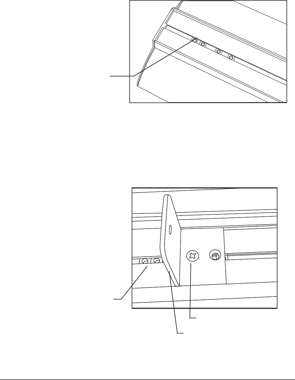
Mounting Your System:
Four captive nuts are located in a slider on the backside of the T9601 transmitter. These are used to
secure the mounting brackets to the unit. The brackets may be mounted in several configurations de-
pendent upon the mounting surface.
1. Position the non-foam padded mounting bracket so that the side with the two holes (laying flat on
the slider) are pointing towards the antenna end of the transmitter.
2. Align the holes with two of the captive nuts.
3. Insert the 2 screws into the holes. Do not fully tighten screws.
4. Repeat steps 1-3 with the foam-padded mounting bracket. The two holes should be pointing op-
posite the antenna end of the transmitter (foam padding should be facing the opposite bracket).
Long Range Systems 5T9601 User Manual
Captive Nuts
Captive Nuts
Mounting Bracket
Screws
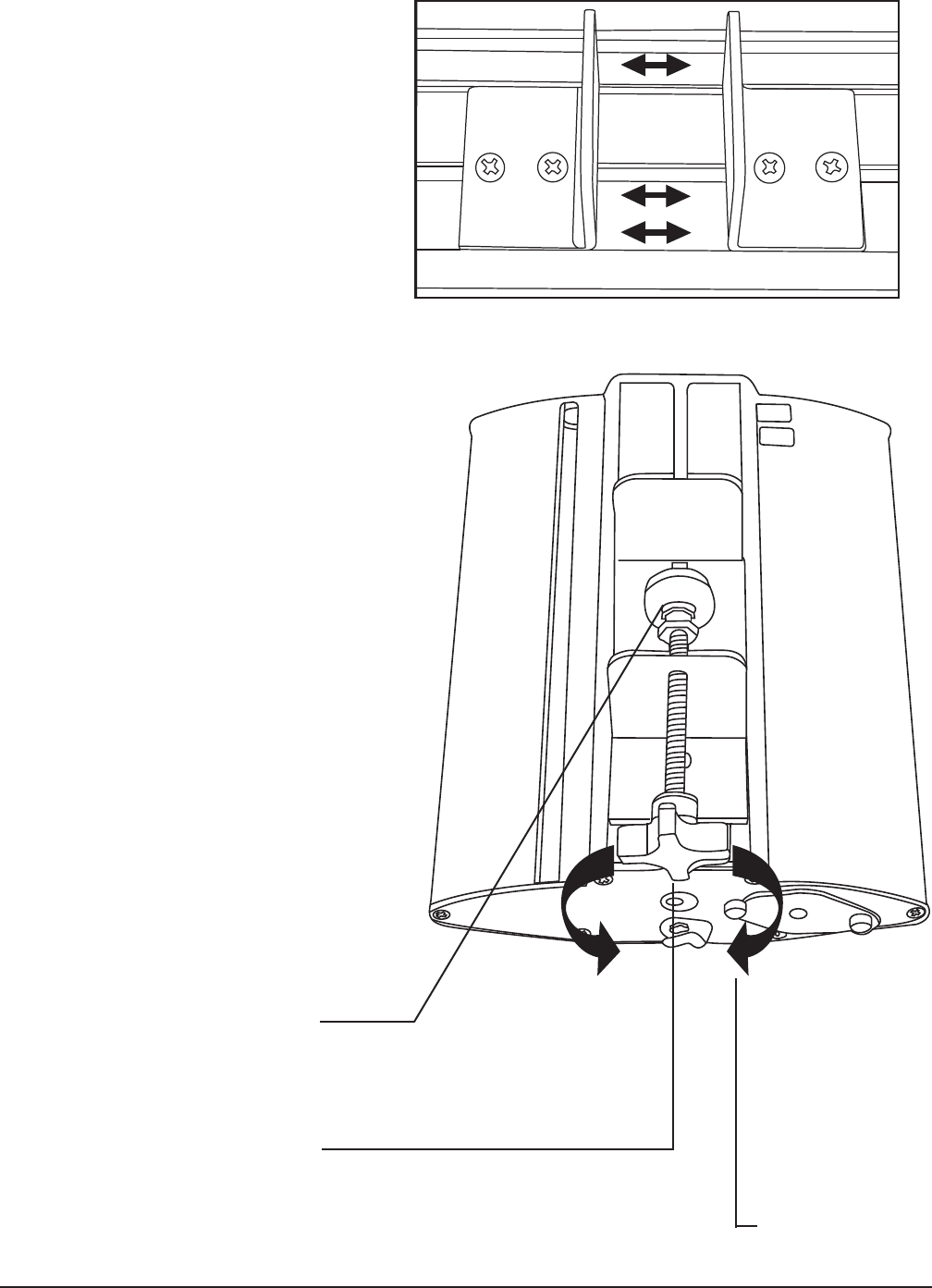
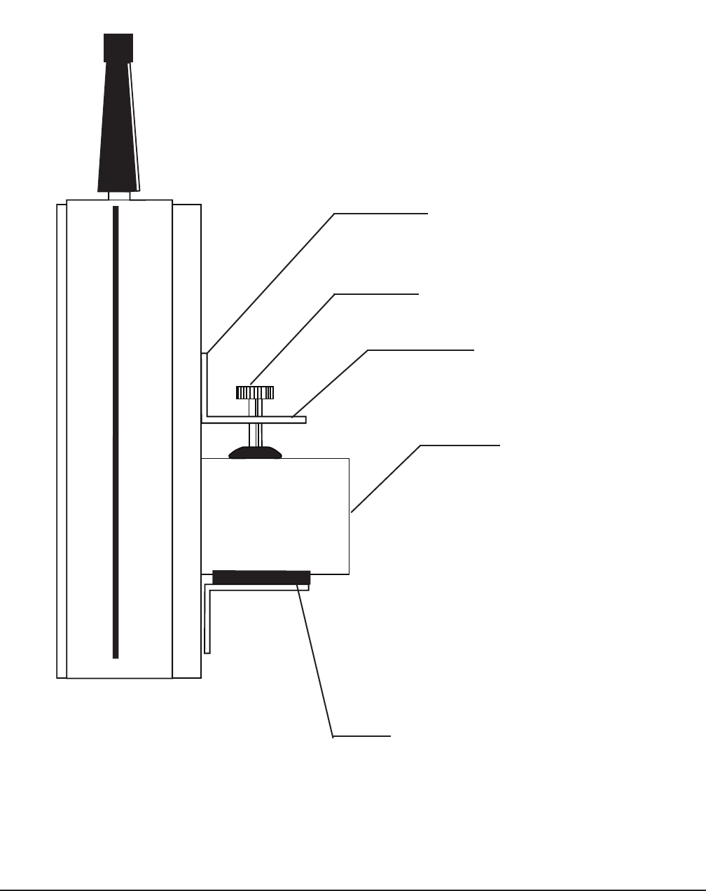
5. Adjust the distance between the
brackets to fit the mounting surface.
6. Securely tighten all captive screws.
7. In a clockwise motion, turn the
thumbscrew into the non-foam
padded mounting bracket.
8. Attach and screw the thumbscrew
clamp foot to the thumbscrew.
9. Holding the transmitter steady, po-
sition the foam padded side of the
mounting bracket onto the bottom
of the mounting surface.
10. In a clockwise motion, screw the
thumbscrew onto the mounting sur-
face, such that the transmitter is po-
sitioned firmly onto the surface.
Long Range Systems 6T9601 User Manual
Thumbscrew Clamp Foot
Turn Clockwise to Tighten
Turn Counter-
Clockwise to
Loosen
Long Range Systems 7T9601 User Manual
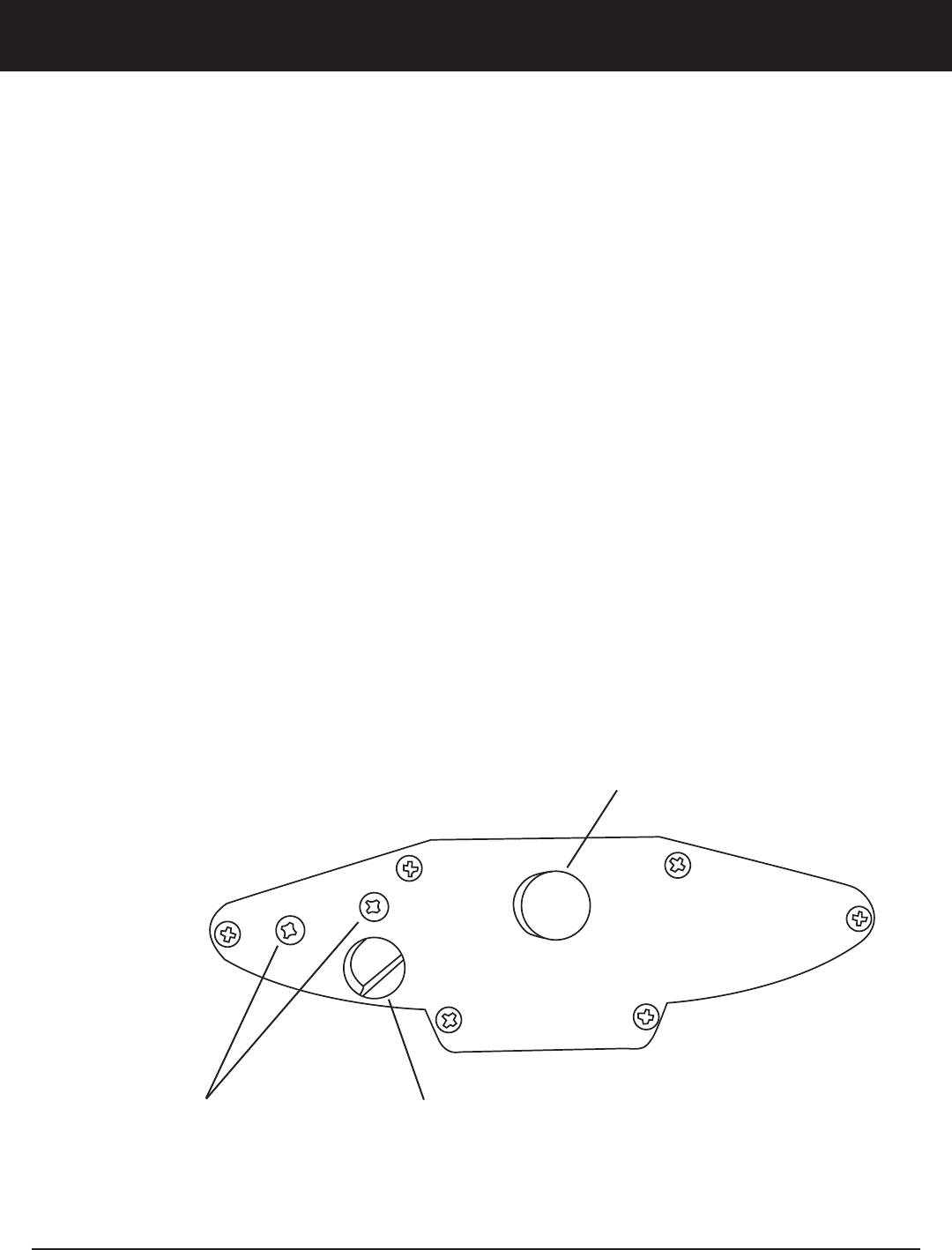
Bracket Mounting Suggestions
The basic mounting suggestion is shown here.
Mounting Bracket without Foam
Padding
Thumbscrew
Thumbscrew Clamp Foot
Mounting Surface
Mounting Bracket with Foam
Padding

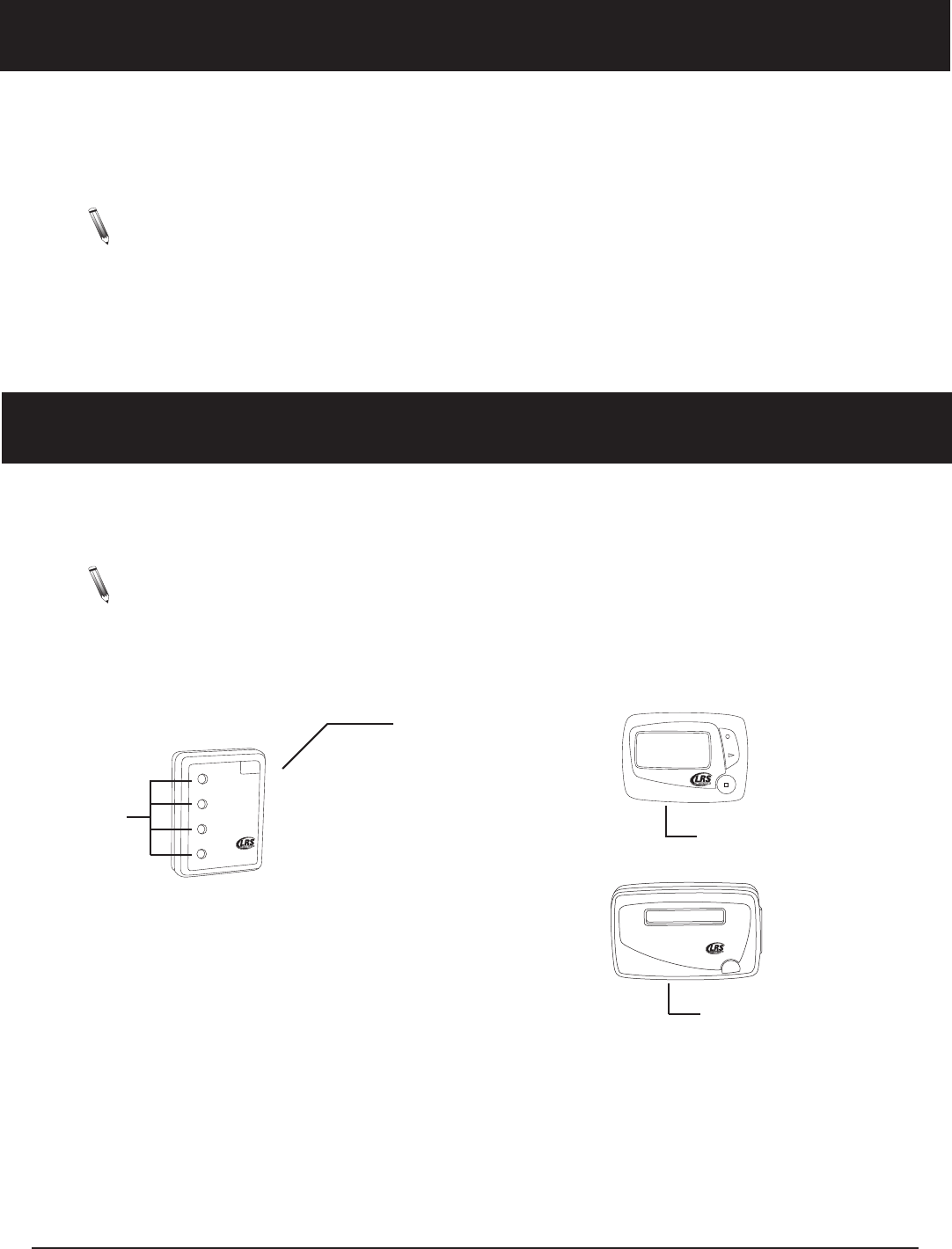
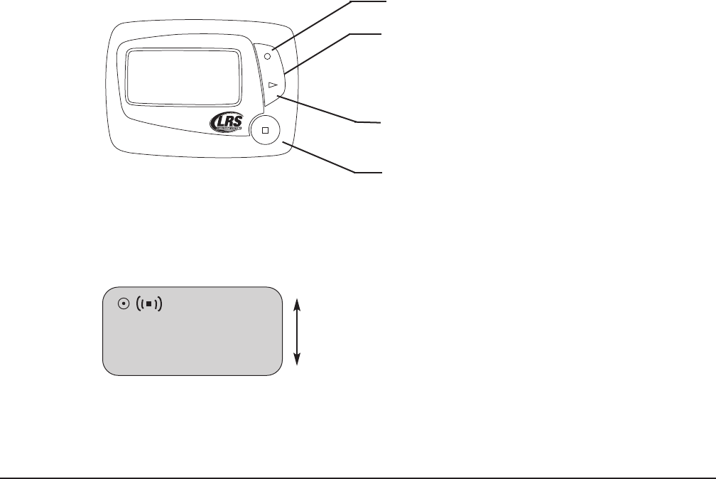
Transmitter/Keypad Elements
Pager Reset Terminals:
Used to reset pagers before reprogramming.
Dry-Erase Server Board:
Write the staff names on the label next to their pager number with a NON-PERMANENT, Dry-Erase
Marker or grease pencil.
Keypad Functions
Before using the keypad, read the following key descriptions:
Function Keys:
The function keys are located on the last row of the transmitter keypad.
PROG – Used when altering system settings, functions, and programming pagers
PGR– Used when entering pager numbers above 16
CLR – Used to clear an entry
ENT – Used to enter changes to system settings, functions, and to send a page
Vibration Keys
V1, V2 and V3 select the number of vibrations a pager will respond with. This button is pressed be-
fore paging a pager. Sends message 1, 2 or 3 to Alpha pagers.
Number Keys:
Number keys 1 through 16 are “one touch” keys to instantly page pagers 1 – 16. Number 10 is also
0 when programming or paging pagers numbered above 16.
Long Range Systems 8T9601 User Manual

Basic Paging Operations
The T9601 factory defaults are the most commonly used settings (System ID = 0, Vibration Mode = 1).
Paging
For pagers numbered 1 – 16:
1. Press the pager number on the keypad unit
2. The unit will automatically send a page
For pagers numbered 17 and higher:
NOTE: Pagers can be numbered up to 999
1. Press PGR
2. Enter the pager number (using #’s 1 – 9 and 10 [as zero])
3. Press ENT
When a page is sent and received:
• Star Pagers – will flash and vibrate
• Rechargeable and battery operated Alpha Pagers – will display “Kitchen <Station #>“ Example:
Kitchen 1
Page A Manager Pager
1. Press PGR
2. Enter the manager pager number
3. Press ENT
When manager pager is set and a page is received:
• Rechargeable and battery operated Alpha Pagers – will display “Manager to Kitchen <Station
#>”
Example: Manager to Kitchen 1
All Call Page
If all pagers need to be called at once,
1. Press PGR
2. Press 0
3. Press the ENT
Alternate Method if “All Call” is enabled (See p. 10 “Set Up All Call”)
1. Press button “16” on transmitter keypad
When All Call Page is enabled and a page is received:
• Star Pagers will flash and vibrate
• Rechargeable and battery operated Alpha Pagers will display “All Page Kitchen <Station #>”
Example: All Page Kitchen 1
Long Range Systems 9T9601 User Manual

System Settings
Setting the Vibration Mode
NOTE: The factory default setting for vibration mode is 1 vibration. (EX: When a page is sent from
the transmitter, the pager will vibrate once)
To set the vibration mode:
1. Press PROG
2. Enter 9 - 2 - #
• 1 vibration: # = 1
• 2 vibrations: # = 2
• 3 vibrations: # = 3
3. Press ENT
Set the Vibration Strength (Only Appicable to the SP5)
The strength of a pager’s vibration when paged can be set.
To adjust the vibration level, between 0 (minimum) and 9 (maximum):
1. Press PROG
2. Enter 9 - 4 - # (# = 0 – 9)
3. Press ENT
• No vibration: # = 0
• Mid level vibration: # = 5
• Maximum vibration: # = 9
System Reset
In certian situations the T9601 may require a system reset before operating properly. When the system is
reset, the Restaurant ID (see pg. 11) and vibration mode (see pg. 10) will be set to factory default.
To reset the transmitter to factory default:
1. Press PROG
2. Enter 0-0-0 and press ENTER
Long Range Systems 10 T9601 User Manual

Setup All Call
‘All Call’ sends a page to all pagers at once. When ‘All Call’ is enabled, pressing the number “16” on the key-
pad will perform this function.
To enable:
1. Press PROG
2. Enter 9 - 3 - 5
3. Press ENT
To disable:
1. Press PROG
2. Enter 9 - 3 - 4
3. Press ENT
Station ID
When more than one transmitter is being used on the same System ID, a station ID can be set to identify
which transmitter the page came from. The station ID will display when a page is sent.
To set:
1. Press PROG
2. Enter 9 - 6 - # (# = Station ID: 1 – 9)
3. Press ENT
System ID
The system ID is used to keep neighboring paging systems from interfering with each other. This setting
should only be cahnges at the advice of an LRS custmer support representative.
To change the ID:
1. Press PROG
2. Enter 9 - # - # (# = System ID: 00 – 19) (EX: 9 – 0 – 3, System ID = 3)
3. Press ENT
Set Simultaneous Manager Paging
This feature allows the manager to receive a message anytime a server is paged.
NOTE: This function works with LRS Alpha pagers only.
To turn on:
1. Press PROG
2. Enter 9 - 5 - 1
3. Press ENT
Long Range Systems 11 T9601 User Manual

4. LCD screen on transmitter will display On
When a simultaneous manager page is received:
• Rechargeable and battery operated Alpha Pagers – will display “Server #: Kitchen <Station #>”
Example: Server 5: Kitchen 1
To turn off:
1. Press PROG
2. Enter 9 - 5 - 2
3. Press ENT
4. The LCD screen on the transmitter will display Off
Setup Duty Pager
Duty pager is used to remind someone of a task that must be completed at specified intervals. A duty re-
minder page is sent to the assigned pager at preset time intervals. The system’s “time” must be set prior to
enabling duty pager.
To Enable:
1. Press PROG
2. Enter 9 - 8 - 0
3. Press ENT
• At dut (duty), enter the pager number
• Press ENT
• At INT, enter the time (interval) in minutes for the reminder page
• Press ENT
• At Str, enter the time of day the task begins: hh (hour) mm (minute) (ex: 10 00)
• Press ENT
• Press PGR for A (AM) or ENT for P (PM)
• At Stp, enter the time of day the task ends: hh (hour) mm (minute) (ex: 12 00)
• Press ENT
• Select A (AM) [by pressing PGR] or P (PM) [by pressing ENT]
When duty pager is set and an interval page is received:
• Star Pagers – will flash and vibrate
• Rechargeable and battery operated Alpha Pagers – will display “Reminder Message: Kitchen
<Station #>” Example: Reminder Message: Kitchen 1
To Disable:
1. Press PROG
2. Enter 9 - 8 - 0
3. Press ENT
4. At dut (duty), enter “0”
5. Press ENT
Long Range Systems 12 T9601 User Manual

Restart Duty Timer
If a task is performed early, the timer can be reset to start the interval over.
To restart:
1. Press PROG
2. Enter 9-8-1
3. Press ENT
Set Time and Date
Time and date are not required for normal use; however, it should be set if duty pager is enabled, and if a
time is required for Alpha pagers.
NOTE: Time and date should be reset at each startup
To set time:
1. Press PROG
2. Enter 9 - 3 - 2
3. Press ENT
• At the tin (time) prompt, enter the hh (hour) and the mm (minute)
• Press ENT
• Press PGR for A (AM) or ENT for P (PM)
To set date:
1. Press PROG
2. Enter 9 - 3 - 3
3. Press ENT
• At the (month) prompt, type the mm (month)
• Press ENT
• At the (day) prompt, type the dd (day)
• Press ENT
AP
PROG PGR CLR ENT
Long Range Systems 13 T9601 User Manual
Select for PM
Select for AM

• At the (year) prompt, type the yy (year)
• Press ENT.
Send Time and Date to Alpha pagers
The T9601 automatically sends the date and time every minute. However, you can also manually send
time/date to all Alpha pagers using the transmitter keypad.
To send time/date:
1. Press PROG
2. Enter 9 - 3 - 1
3. Press ENT
Set POCSAG Start
In systems using both Alpha pagers and Star pagers, a start for the POCSAG (alpha) pagers must be set.
The default POCSAG start for alpha pagers is 50. Alpha pagers should be programmed using a number equal
to or above 50. Star (SP4) pagers should be programmed using a number below 50.
To setup:
1. Press PROG
2. Enter 8 - # - # (# is a number between 01 and 99)
3. Press ENT
Set Language
The T9601 provides the option to transmit preset messages to alphanumeric pagers in different languages.
The following languages are available: English, Spanish, French, German, Italian, and Portuguese.
To set a language:
English (default)
1. Press PROG
2. Enter 9 - 5 - #
3. Press ENT
• English: # = 3
• Spanish: # = 4
• French: # = 5
• German: # = 6
• Italian: # = 7
• Portuguese: # = 8
Long Range Systems 14 T9601 User Manual

Key Tone
The default key tone for the T9601 is a ‘beep’ sound when keypad buttons are pressed. However, the key tone
‘beep’ sound can be disabled.
To enable:
1. Press PROG
2. Enter 9 - 8 - 6
3. Press ENT
To disable:
1. Press PROG
2. Enter 9 - 8 - 7
3. Press ENT
Long Range Systems 15 T9601 User Manual

Maintenance Checks
Range Test
Perform a range test to determine the effective range of the T9601.
NOTE: Be sure to remove pagers from the charging base before performing the range test.
1. Press PROG - 9 - 9 - 7 - ENT
2. The screen will display “tst” and then a “-” (dash) will appear
3. When the “-” (dash) begins scrolling across the screen, pagers will vibrate every 5 seconds (as long
as they are receiving the signal)
4. Take a pager and walk around the area to verify the pager operates in all areas (the pager will stop
vibrating when it is out of range)
5. Press ENT To stop the range test
Anti-Theft
Anti-theft is used to alert staff carrying alpha pagers that they are leaving the premises while still carrying
the pager.
NOTE: Anti-Theft only works with alphanumeric pagers.
To Turn On:
1. Press PROG
2. Enter 9 - 9 - 9
3. Press ENT
To Turn Off:
1. Press PROG
2. Enter 9 - 9 - 8
3. Press ENT
When Activated:
• The transmitter sends a signal to alpha pagers, and if the signal is not received, the pager will
emit a continuous beep sound until it is returned to the charging unit or is back within range.
• The LED screen on the alphanumeric pagers will display “OUT OF RANGE”.
Cleaning The System
Caution: Do not use any cleaning solutions containing chloride
When cleaning the T9601 system and its components (pagers, charging base), DO NOT use any cleaning
products that contain Chloride. These products will damage the material and will stain the surface.
NOTE: Be sure to unplug the T9601 system and charging base before cleaning.
To Clean:
• Using a damp cloth, wipe the exterior of the system’s components
Long Range Systems 16 T9601 User Manual
Programming Pagers
If a new pager number needs to be assigned to a pager, Star (SP5) and Alpha pagers can be reprogrammed
from the T9601 transmitter. If you would like to assign or reassign numbers to pagers, contact LRS to verify
your restaurant ID before proceeding.
To Program Pagers:
1. Be sure the POCSAG start is correct for programming pager types (see “Set POCSAG Start” pg. 14)
2. Pagers:
• Remove rechargeable pagers from the charger (or reset by touching the silver nodes on the
pager to the reset terminal on the transmitter) and wait until it stops vibrating
• Turn battery powered pagers on and then off (or remove and reinstall the battery) and wait until
it stops vibrating and/or beeping
4. Press PROG
5. Enter the number you wish to assign to the pager (Choose #: 1 - 999)
6. Press PROG
• Star pagers will slowly vibrate and light up then dim to off
• Alpha pagers will beep 4 times and then stop
7. Once programming is complete, page the pager to ensure it is programmed correctly
(See “Basic Paging Operations” p. 9)
Top View of the T9601
Long Range Systems 17 T9601 User Manual
Reset Terminals Marker Holder
Antenna

Assign Manager Pager
A manager pager can be assigned to notify a manager what station they are needed at when a page is re-
ceived. Only LRS alphanumeric pagers (rechargeable and battery operated) can be set as manager pagers.
Set Manager Pager
1. Press PROG
2. Enter 9 - 8 - 5
3. Press ENT
4. At Ngr (manager), enter the pager number
5. Press ENT
NOTE: Manager pager cannot be disabled. However, you can reassign manager pager to a differ-
ent pager number. To reassign, follow the steps for setting manager pager and enter a dif-
ferent pager number.
System Specifications
Notice: Operation is subject to the following:
• This device may not cause interference.
• This device will accept any interference including interference that may cause undesired oper-
ation of the unit.
T9601
Required Voltage: One-110V outlet for the T9601 transmitter
(Batteries: This option currently NOT available)
Operating Frequency: 467.750MHz
Radiated Power: <4900 micro-volts/meter
Operating Range: Dependent upon the paging environment
Long Range Systems 18 T9601 User Manual

T9601 Quick Programming Functions Guide
When programming functions:
1.Press PROG
2. Enter the Function Code
3. Press ENT
* Make sure POCSAG Start is set
Long Range Systems 19 T9601 User Manual
Function Function
Code Notes
Reset 0
System settings default to:
Station ID = 1
System ID = 0
Vibration 1, 2, or 3 9 2 # # = Vibration = 1, 2, or 3
POCSAG Start 8 # # ## = Start = 01 – 99
System ID (Restaurant ID) 9 ## ## = ID = 00 – 19
Time: Send to Pager 9 3 1 Sends Time and Date to Alpha Pagers
Set Time 9 3 2 At TIM enter hh mm (Hour, Minute) Press ENT
Press A or P (AM/PM)
Set Date 9 3 3
At DTE enter mm (Month), press ENT
dd (Day), press ENT
yy (Year), press ENT
Setup All Call 9 3 # # = 5= ON # = 4 = OFF
Vibration Strength 9 4 # (# = 1 – 9) # = 0 = OFF
# = 1 = Minimum # = 9 = Maximum
Simultaneous Manager Paging 9 5 # # = 1 = ON # = 2 = OFF
Language 9 5 #
# = Language
• English = 3 • Spanish = 4 • French = 5
• German = 6 • Italian = 7 • Portuguese = 8
Station ID 9 6 # # = ID = 1 – 9
Firmware Version 9 7 5
Duty Pager Setup 9 8 0
At dut , enter pager #, and press ENT(Pager # = 0 disables)
At Int, enter interval time and press ENT
At Str, enter start time and press ENT
At Stp, enter stop time and press ENT
Duty pager Reset 9 8 1 Restarts interval timer on duty pager
Manager Pager 9 8 5 At Mgr, enter the pager number
Press ENT
Enable/Disable Key Tone Beep 9 8 # # = 6 = ON # = 7 = OFF
Enable/Disable AM paging 9 9 # # = 1 = ON # = 0 = OFF
Range Test 9 9 7 Enables Range Test (Press ENT to stop)
POCSAG anti theft ON/OFF 9 9 # # = 9 = ON # = 8 = OFF
All Call Paging Press PGR Enter “0” and Press ENT
One Touch Paging Press the
pager # Pager #’s (1 – 16)
High Number Paging Press PGR Enter pager # (1-999) and Press ENT
*Programming Pagers Press PROG Enter pager # (1-999) and Press PROG

Troubleshooting
Transmitter Unit
The Light On The Keypad Display Does Not Come On When A Key Is Pressed
• Check the charging power supply by plugging the power/charging supply used for the pager
charger into the transmitter unit.
• If the display light comes on, there may be a problem with the T9601 power/charging supply.
Call LRS Customer Support to order a new power supply.
• If the display still does not light, there may be a problem with the transmitter unit. Call LRS Cus-
tomer Support for assistance.
The Keypad Display Is Functioning Properly But The Pager Does Not Receive the Page
• Perform a system reset (see “System Reset” pg. 10).
• Make sure that pagers are on the same system ID (see “Set System ID” if ID is not “0”)
• Complete the steps for paging a pager (see “Paging” pg. 9).
• If the pager still does not receive the page, call LRS Customer Support for assistance.
Pagers
Pager Charge Lights Do Not Come On
Charging slots should display a single red charge light when pagers are placed in the charger, and are charg-
ing correctly. If the red charge light is not visible on some or all charging slots, review the following recom-
mendations to determine and solve the problem..
• Make sure the pagers are completely inserted into the charging slot.
• The power supply may be defective. Try plugging the power supply used for the transmitter
into the pager charger.
• You might have more pagers charging on one power supply than recommended. Only 25 pagers
can be charged on one 12V power supply. If you have more than 25 pagers, you should call LRS
to order additional chargers.
• You might have a jumper wire that is not properly connected. Look on the side of your charger
and verify that all wires are connected properly. If they are connected, then the metal contacts
on your pager may be dirty. Using a damp rag, clean the 2 metal contacts on the back of each
pager.
• Be sure that your staff is not disconnecting the power supply at anytime or that you do not have
the charger connected to a circuit that automatically shuts off after hours. The charging base
should be plugged into a power outlet that is “ON” at all times (Be sure the pager is not in the
charger backwards).
• If none of these recommendations solve your problem, call LRS Customer Support to deter-
mine the problem at 800-437-4996.
Battery Powered Pager Shows Low Battery:
Replace the battery.
Long Range Systems 20 T9601 User Manual

Service Questions and Answers
Should your paging system ever fail or should you need additional paging equipment, call Long Range Sys-
tems at (800) 437-4996.
Normal Business Hours
Monday – Friday 8:30 am to 5:00 pm Central Time.
Weekend or Evening Emergencies:
• Long Range Systems provides 24/7 live technical support.
• Please keep in mind that replacement options are limited on weekends and holidays.
LRS PAGERS AVAILABLE FOR THE T9601
(These pagers are sold separately)
• SP5 Rechargeable Alpha
• LRS 4-Line Alpha
• Star Rechargeable Pager
Long Range Systems 21 T9601 User Manual
LRS Pagers Available for the T9601
Using the SP5 1-Line Rechargeable Alpha Numeric Pager
Charging
Any rechargeable pager will require the use of an LRS charger. The SP5 uses the Charger 5 (CH-R5).
1. Place the pager in the charger
2. Allow unit to charge fully overnight (at least 24 hours)
3. Remove from charger and the pager will vibrate or beep
4. The LCD will show:
• C1: [System ID] Pager ID (Ex. C1: [0] 91)
• Programming Active
• Blank screen or Date and Time (if set) (Ex. 10/07/2008 12:05 am)
5. Return the pager to the charger at the end of each day
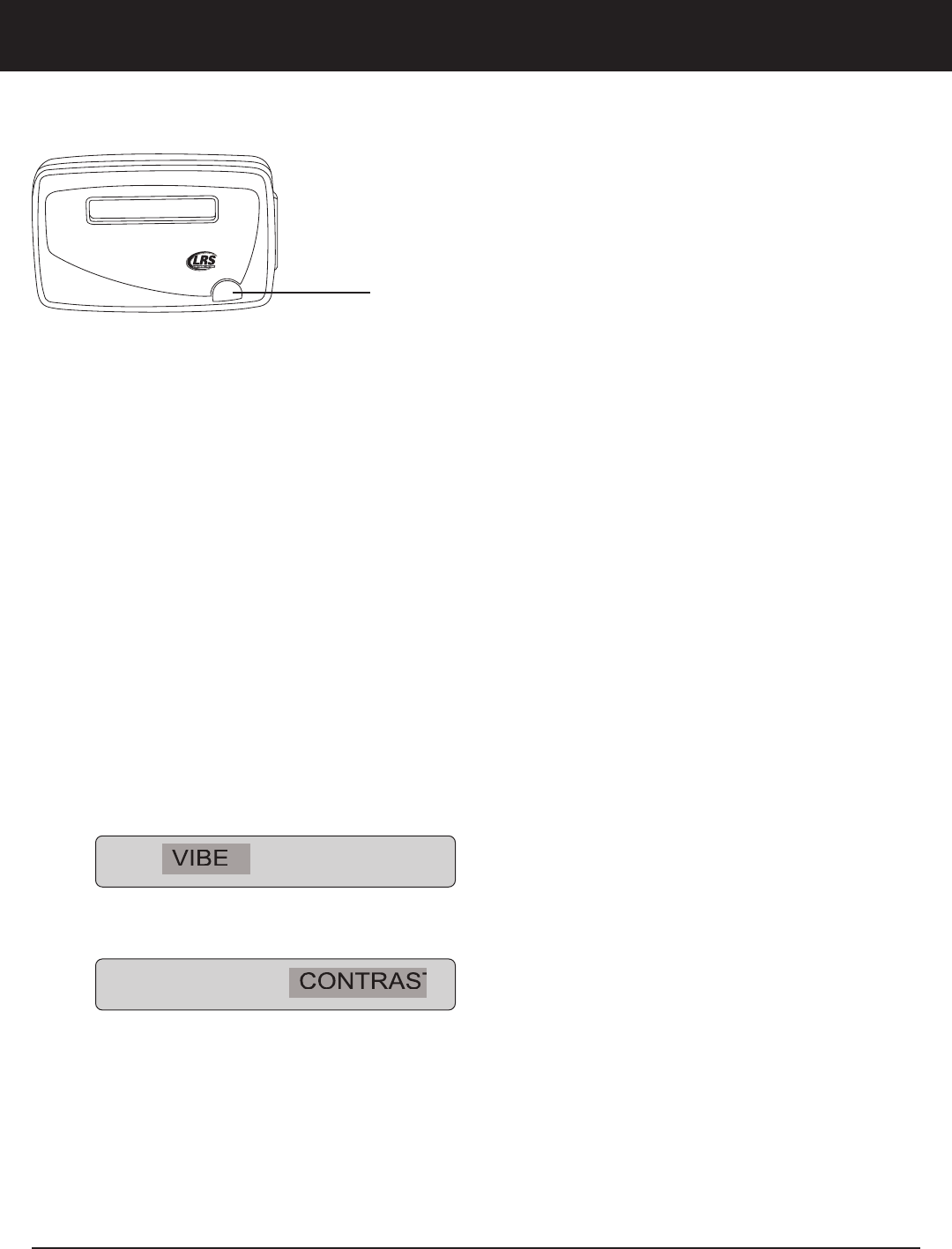
Menus
To access the vibe/contrast menu:
1. Remove the pager from the charger.
2. While vibrating or beeping, press and hold the Select button for 8 seconds.
The menu will display:
3. If you PRESS and RELEASE the Select Button, the menu selector will scroll to the right and will high-
light “Contrast
4. To exit this menu wait 8 seconds
5. To re-enter the vibe/contrast menu at anytime, repeat Step 1
Vibe
To set the Vibration Level:
1. Remove the pager from the charger
2. While vibrating or beeping, press and hold the Select Button for 5-8 seconds
VIBE CONTRAST
VIBE CONTRAST
www.pager.net
Long Range Systems 22 T9601 User Manual
Select Button
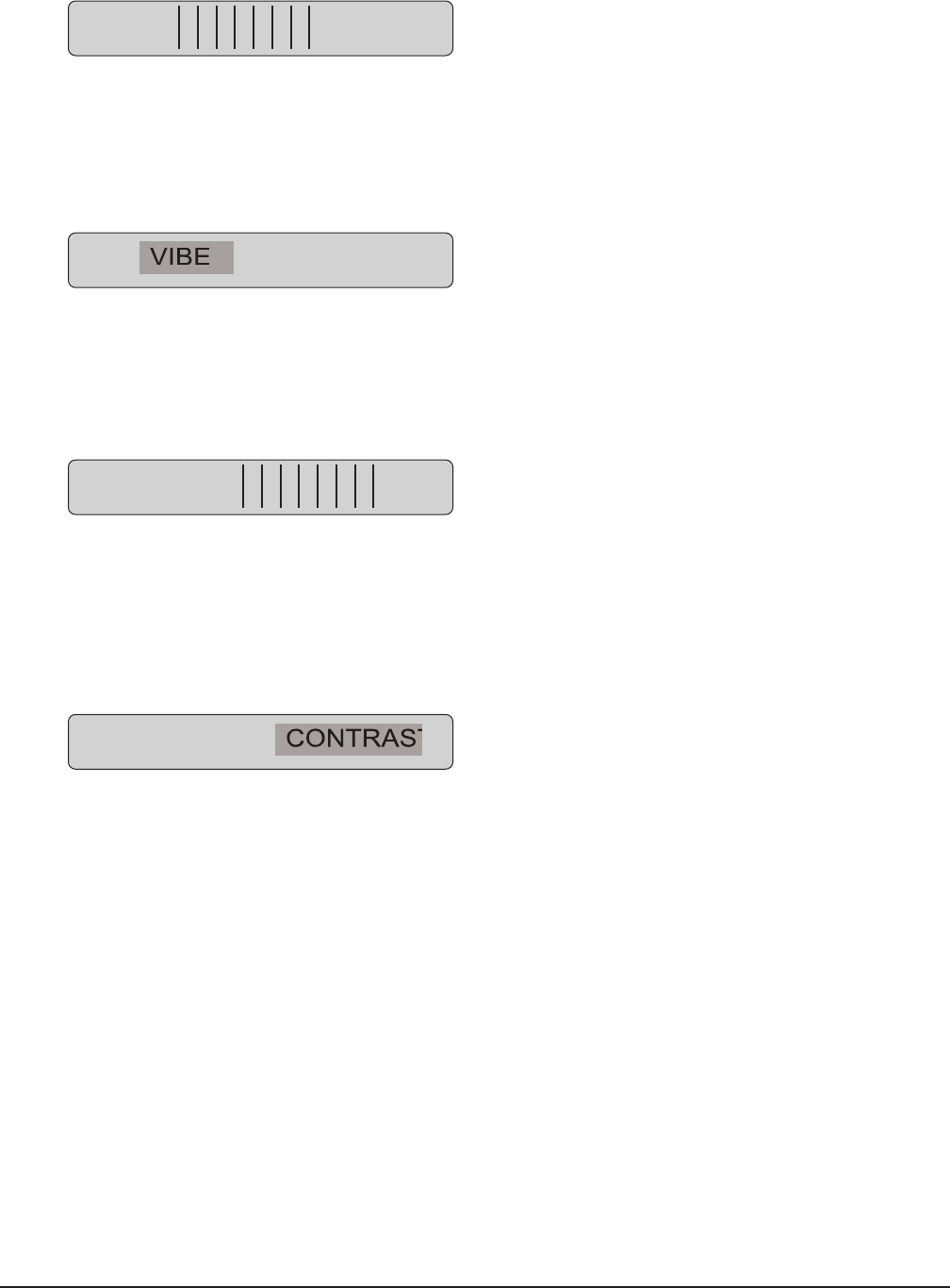
3. Highlight the Vibe selection then PRESS and HOLD the Select Button until the screen shows.
4. Press or hold the Select Button until the desired vibration level is selected
5. If holding down on the Select Button, the vibe level will increase to max and then decrease to-
wards the minimum
6. Release the Select Button when desired vibration level has been reached
7. To exit, wait 8 seconds and the pager will go back to the vibe/contrast menu
Contrast
To set the Contrast Level
1. Remove the pager from the charger
2. While vibrating or beeping, press and hold the Select Button for 5-8 seconds
3. Highlight the Contrast selection then PRESS and HOLD the Select Button until the screen shows.
4. Press or hold the Select Button until the desired contrast is selected
5. If holding down on the Select Button, the contrast level will increase to Max (NOTE: screen could
be dark and hard to read)
6. Release the Select Button and press or hold again to change the level back towards the minimum
or until your desired contrast is selected
7. To exit, wait 8 seconds and the pager will go back to the vibe/contrast menu
8. To exit this menu wait 8 additional seconds
Settings
To view the current pager settings
1. Remove pager from the charger or reset on the T9601 reset terminals.
2. Press the Select Button repeatedly to scroll through the settings:
C1: [System ID number] and Pager ID number
C2: [System ID number] and All Page number
C3: [System ID number] and System ID number
G: Group number
Enc: Encryption enabled (128) or none
Ver: Current Firmware Version
3. To exit, wait 8 seconds.
VIBE CONTRAST
CONTRAST:
VIBE CONTRAST
VIBE
Long Range Systems 23 T9601 User Manual
Messages
The pager stores the last 5 received messages.
To view the messages:
1. At the (blank screen/time & date) menu display, press the Select Button once
2. Messages 2 lines in length will show a > symbol at the end of the first line and a < symbol at the be-
ginning of the second line
3. Messages over 2 lines in length, the middle lines will show “< the next line of the message >”
4. Press the Select Button to continue scrolling forward through the message or messages
Time
The SP5 pager will display the current time. The T9601 transmitter automatically updates this feature. If the
time does not appear, a flashing star will appear on the right side of LCD to show the pager is operational.
• To send time information to the pager from the transmitter, see “Send Date/Time” pg. 13
Programming
To reset and reprogram the pager, see “Programming Pagers” p. 17 of this document.
Using the 4-Line Alpha Numeric Pager
Menus
Read All
10/25 10:38am
UP
SCROLL
DN
www.pager.net
UP
SCROLL DOWN
DOWN
SELECT/READ
BUTTON
Long Range Systems 24 T9601 User Manual
Selecting functions
1. From Read All screen, press Up (or Dn) Scroll button until desired selection displays
2. Press Read/Select button to select item
3. Press Up (or Dn) Scroll button to choose/adjust
4. Press Read/Select to confirm/set
Power On/Off
Set ON (if unit is off)
1. Press and hold Scroll Up until YES/NO shows.
2. At “Power ON?” use Up (or Dn) Scroll button to select YES
3. Press Read/Select button to set
Set OFF
1. Using the Up (or Dn) scroll button scroll until display shows “Power OFF?”
2. Press Read/Select button to set power on/off
3. At “Power OFF?” screen, use Up (or Dn) Scroll button to select YES
4. Press Read/Select button to set
Read Message
• Messages are displayed upon receipt.
• Press Read/Select to display.
To review stored messages:
1. Select “Read All?”
2. Press Read/Select to display messages and time stamps
3. Use the Up (or Dn) Scroll button to scroll through messages
Delete Messages
1. Using the Up (or Dn) scroll button, scroll until display shows “Delete All?”
2. Press Read/Select
3. Use the Up (or Dn) scroll button to select Yes or No
4. Press Read/Select button to confirm
Time/Date Set
1. Using the Up (or Dn) scroll button scroll until display shows “Set Time/Date”
2. Press Read/Select to set time/date
3. Press Up (or Dn) scroll button to set each time or date segment and press Read/Select to move
through the segments
UP
SCROLL
DN
[01/16] 01/02/2008
10:04 AM
Appel Telephonique
Long Range Systems 25 T9601 User Manual

Set Contrast
1. Using the Up (or Dn) scroll button scroll until display shows “Set Contrast”
2. Press Read/Select
3. Use the Up (or Dn) scroll button to adjust
4. Press Read/Select to confirm
Auto ON/OFF
1. Using the Up (or Dn) scroll button scroll until display shows “Auto ON/OFF”
2. Press Read/Select to set auto on/off
3. Use the Up (or Dn) scroll button to select On or Off
4. Press Up (or Dn) scroll button to set on/off time and press Read/Select to move through the seg-
ments
Set Key Tone On/Off
1. Using the Up (or Dn) scroll button scroll until display shows “Set Key Tone”
2. Press Read/Select to set key tone on/off
3. Use the Up (or Dn) scroll button to select On or Off
4. Press Read/Select to set
Select Alert Mode
1. Using the Up (or Dn) scroll button scroll until display shows “Set Alert Mode”
2. Use the Up (or Dn) scroll button to select Beep/Vibe Off
3. Press Read/Select to set:
Beep - Use the Up (or Dn) scroll button to select:
• Select Loud or Soft and press Read/Select to set
• Select Duration (seconds) and press Read/Select to set
Vibe Off - Use the Up (or Dn) scroll button to select
• Press Read/Select to set
Battery
The RX-E 4-Line Alpha pager uses 1 AAA Battery.
Programming
To program the pager see pg. 17
Long Range Systems 26 T9601 User Manual

Using the Star Pager
Charging
Any rechargeable pager will require use of an LRS charger. The Star Pager (SP4) uses the Charger 9 (CH-R9).
1. Place the pager in the charger
2. Allow unit to charge fully overnight (at least 24 hours)
3. Remove from charger, and pager will vibrate, beep, and light
4. Replace the pager in the charger at the end of each day
Messages
The pager can vibrate, beep, and light up message lights.
Vibration
• Star Pagers will vibrate a certain number of times depending on the vibe mode - V1, V2 or V3
that is selected from the transmitter keypad when sending a page
• Vibrations can be used to send additional information or to identify 1 of 3 stations
• By sending messages using vibrations, the person being paged will not have to look down to
see the lights display, instead the vibrations will let them know what station the page came from
Example: V1 = Station 1, V2 = Station 2, V3 = Station 3
To set vibration – see p.10
LED Messaging
• The LED lights located on the front of the Star pager can be used to represent Station ID’s in lo-
cations where more than one T9601 transmitter is being used
• Each T9601 transmitter in use represents a “Station ID”
• When a page is sent, the LED lights, letting staff know which transmitter (Station ID) the page
came from
Example:
• LED 1 lights = Station 1
• LED 2 lights = Station 2
• LED 1 & 4 light = Station 5
To set LED messaging – see p.11
Programming
To program the Star Pager, see page 17.
1
2
3
4
800.437.4996
www.pager.net
1
4
Long Range Systems 27 T9601 User Manual

Cleaning & Charging Instructions For LRS Paging Equipment
Cleaning:
LRS pagers are made from industrial-strength, polycarbonate material. However, this
material is susceptible to hairline cracking if non-approved cleaners are used. When clean-
ing LRS pagers, we recommend only using ISOPROPYL ALCOHOL-BASED CLEANERS.
To clean the equipment:
1. Take a clean rag and an isopropyl-alcohol based cleaner
2. Soak the clean rag with the isopropyl alcohol cleaner
3. Wipe down the pagers or equipment.
Cleaning equipment with any other non-approved cleaners can weaken plastic and
cause hairline cracks. Pagers and equipment that are cleaned with unapproved clean-
ers and suffer cracking will not be covered under warranty.
Do not submerge any LRS paging equipment in any type of liquid as this will also dam-
age the equipment and is not covered under the standard warranty.
Charging:
Place rechargeable pagers on the charger and let them charge for 8 hours prior to first use.
Rechargeable pagers should be kept on charge even during extremely long periods of
inactivity.
Only 12 VDC power supplies should be used with LRS chargers and transmitters. DC
power supplies will cause damage to equipment that is not covered under the standard
warranty.
Should you have any questions, please contact the LRS Customer Service Department
at 800.437.4996.
Long Range Systems 28 T9601 User Manual
XU-0026 061914