LongSung Technology U3500 MODULE User Manual USERS MANUAL
LongSung Technology (Shanghai)Co.,Ltd. MODULE USERS MANUAL
USERS MANUAL
U3500_Hardware_User_Guide _V2.0 Page 1 of 82
U3500_Hardware_User_Guide _V2.0

U3500_Hardware_User_Guide _V2.0 Page 2 of 82
IMPORTANT NOTICE
COPYRIGHT NOTICE
Copyright©2010, LongSung Technology (Shanghai) Co., Ltd. All rights
reserved.
TRADEMARKS
LongSung Technology (Shanghai) Co., Ltd’s products are exclusively owned by
LongSung Technology (Shanghai) Co., Ltd. References to other companies and
their products use trademarks owned by the respective companies and are for
reference purpose only.
CONFIDENTIALITY
The information contained here (including any attachments) is confidential. The
recipient here acknowledges the confidentiality of this document, and except for
the specific purpose, this document shall not be disclosed to any third party.
WARRANTY DISCLAIMER
LongSung Technology (Shanghai) Co., Ltd makes no representations or
warranties, either express or implied, by or with respect to anything in this
document, and shall not be liable for any implied warranties of merchantability
or fitness for a particular purpose or for any indirect, special or consequential
damages.
NO GUARANTEE
Our company will not take any responsibility for any damage caused by the
customer’s abnormal operation. Please refer to specification and designing
reference guide. Our company have right to modify the document according to
technical requirement with no announcement to the customer.
Federal Communication Commission Interference Statement
This device complies with Part 15 of the FCC Rules. Operation is subject to the
following two conditions: (1) This device may not cause harmful interference,
and (2) this device must accept any interference received, including
interference that may cause undesired operation.
This equipment has been tested and found to comply with the limits for a Class
B digital device, pursuant to Part 15 of the FCC Rules. These limits are
designed to provide reasonable protection against harmful interference in a
residential installation. This equipment generates, uses and can radiate radio
frequency energy and, if not installed and used in accordance with the
instructions, may cause harmful interference to radio communications.
However, there is no guarantee that interference will not occur in a particular
installation. If this equipment does cause harmful interference to radio or
television reception, which can be determined by turning the equipment off and

U3500_Hardware_User_Guide _V2.0 Page 3 of 82
on, the user is encouraged to try to correct the interference by one of the
following measures:
Reorient or relocate the receiving antenna.
Increase the separation between the equipment and receiver.
Connect the equipment into an outlet on a circuit different from that
to which the receiver is connected.
Consult the dealer or an experienced radio/TV technician for help.
FCC Caution: Any changes or modifications not expressly approved by the party
responsible for compliance could void the user's authority to operate this
equipment.
This transmitter must not be co-located or operating in conjunction with any
other antenna or transmitter.
Radiation Exposure Statement:
This equipment complies with FCC radiation exposure limits set forth for an
uncontrolled environment. This equipment should be installed and operated with
minimum distance 20cm between the radiator & your body.
This device is intended only for OEM integrators under the following conditions:
1)The antenna must be installed such that 20 cm is maintained between the antenna
and users.
2)The transmitter module may not be co-located with any other transmitter or antenna.
As long as 2 conditions above are met, further transmitter test will not be required.
However, the OEM integrator is still responsible for testing their end-product for any
additional compliance requirements required with this module installed.
IMPORTANT NOTE: In the event that these conditions can not be met (for example
certain laptop configurations or co-location with another transmitter), then the FCC
authorization is no longer considered valid and the FCC ID can not be used on the final
product. In these circumstances, the OEM integrator will be responsible for re-evaluating
the end product (including the transmitter) and obtaining a separate FCC authorization.
End Product LabelingThis transmitter module is authorized only for use in device where
the antenna may be installed such that 20 cm may be maintained between the antenna
and users. The final end product must be labeled in a visible area with the following:
“Contains FCC ID: XHZU3500”. The grantee's FCC ID can be used only when all FCC
compliance requirements are met.
Manual Information To the End UserThe OEM integrator has to be aware not to provide
information to the end user regarding how to install or remove this RF module in the user’s
manual of the end product which integrates this module.The end user manual shall include
all required regulatory information/warning as show in this manual.

U3500_Hardware_User_Guide _V2.0 Page 4 of 82
Contents
1. Overview .................................................................................................................................. 9
1.1. Purpose of the document ....................................................................................... 9
1.2. Summary ...................................................................................................................... 9
1.3. Correlative documents ............................................................................................ 9
1.4. Document’s history ................................................................................................. 10
1.5. Abbreviations ............................................................................................................ 10
2. Introduction........................................................................................................................... 12
2.1. Key features .............................................................................................................. 14
2.2. Operating modes ..................................................................................................... 16
2.3. Hardware functional block diagram ................................................................. 17
2.4. Hardware interface ................................................................................................. 18
3. Application interfaces description ................................................................................. 20
3.1. 83-pin Stamp hole SMT PAD and 126-pin LGA PAD .................................. 20
3.2. Power supply ............................................................................................................. 27
3.2.1. Power Supply and reference design ..................................................... 27
3.2.1.1. VBAT input ......................................................................................... 27
3.2.1.2. VRTC input ......................................................................................... 28
3.2.1.3. VOUT、VREG_GP2、VREG_MMC voltage output ................. 29
3.2.1.4. POWER_ON input ............................................................................ 29
3.2.1.5. RESET input ....................................................................................... 30
3.2.2. Power on/off control ................................................................................... 31
3.2.2.1. POWER_ON control module power on ..................................... 31
3.2.2.2. VBAT active power on .................................................................... 32
3.2.2.3. AT command power off ................................................................. 33
3.2.2.4. VBAT set low or off to power off mode ................................... 33
3.2.3. RESET control ............................................................................................... 33
3.3. USB interface ............................................................................................................ 35
3.3.1. USB interface description ......................................................................... 35
3.3.2. USB reference circuit ................................................................................. 35
3.3.3. USB driver ...................................................................................................... 37
3.3.3.1. Linux OS load USB driver for U3500 ....................................... 37
3.3.3.2. Linux OS AP use AT to control U3500 ..................................... 39
3.3.3.2. Linux OS AP dial PPP connection ............................................... 41
3.4. UART interface .......................................................................................................... 44
3.4.1. UART interface description ...................................................................... 44
3.4.2. UART interface reference circuit ............................................................ 44
3.4.3. UART interface description ...................................................................... 45
3.4.4. U3500 sleep and awake control ............................................................ 46
3.4.4.1. The prerequisites for module to sleep .................................... 47
3.4.4.2. About sleep and awake questions ............................................ 47

U3500_Hardware_User_Guide _V2.0 Page 5 of 82
3.5. Analog audio interface .......................................................................................... 49
3.5.1. Audio interface description ...................................................................... 49
3.5.2. Audio I/O and earphone connection .................................................... 49
3.5.3. Audio I/O and phone handfree connection ....................................... 49
3.5.4. Audio I/O and phone handset connection ......................................... 50
3.5.5. Analog audio interface reference circuit ............................................. 50
3.6. PCM interface ............................................................................................................ 51
3.6.1. PCM interface description ......................................................................... 52
3.6.2. Auxiliary PCM ................................................................................................ 53
3.6.3. Primary PCM .................................................................................................. 54
3.6.4. Audio parameters control ......................................................................... 56
3.7. USIM/SIM interface ................................................................................................ 57
3.7.1. USIM/SIM interface description ............................................................. 57
3.7.2. USIM/SIM interface reference circuit .................................................. 58
3.8. NETLIGHT output .................................................................................................... 60
3.8.1. NETLIGHT signal description ................................................................... 61
3.8.2. NETLIGHT reference circuit ..................................................................... 61
3.9. ADC interface ............................................................................................................ 61
3.9.1. ADC interface description......................................................................... 62
3.9.2. ADC input reference circuit ..................................................................... 62
3.9.3. Temperature detector circuit .................................................................. 62
3.10. GPIO interface ....................................................................................................... 63
3.11. Antenna interface ................................................................................................. 63
3.11.1. Solder antenna .......................................................................................... 64
3.11.2. RF connector antenna ............................................................................. 65
3.11.2.1. RF cable ............................................................................................ 65
3.11.3. U3500 RF output power ......................................................................... 65
3.11.4. U3500 RF receiver sensitivity .............................................................. 66
3.11.5. U3500 operating frequencies ............................................................... 66
3.11.6. Antenna parameters requirement ...................................................... 66
3.12. Micro SD card interface ...................................................................................... 67
3.12.1. Micro SD card interface description ................................................... 67
3.12.2. Micro SD interface reference circuit .................................................. 67
3.13. Camera interface .................................................................................................. 68
3.13.1. Camera interface description ............................................................... 68
3.13.2. Camera interface reference circuit ..................................................... 69
3.14. Keypad interface ................................................................................................... 70
3.15. LCD interface .......................................................................................................... 70
3.16. 32K_CLK_BT interface ........................................................................................ 71
4. Mechanics ............................................................................................................................... 72
4.1. The view of U3500 .................................................................................................. 72
4.2. Module 3D stack ...................................................................................................... 72
4.3. Module 2D mechanical dimensions .................................................................. 73

U3500_Hardware_User_Guide _V2.0 Page 6 of 82
4.4. Application side decals of U3500 ...................................................................... 73
4.5. RF connector ............................................................................................................. 73
4.5.1. Module side RF connector ........................................................................ 74
4.5.2. Application side RF connector ................................................................ 74
5. Power consumption ............................................................................................................ 76
6. Electrical characteristics ................................................................................................... 78
6.1. Absolute maximum power ratings .................................................................... 78
6.2. Operating temperatures ....................................................................................... 78
6.3. Interface operating status ................................................................................... 80
6.4. Reliability .................................................................................................................... 80
6.5. Electrostatic discharge .......................................................................................... 82

U3500_Hardware_User_Guide _V2.0 Page 7 of 82
Tables
Table1:Document’s update history .......................................................................... 10
Table2:Abbreviation and description ...................................................................... 10
Table3:Key features of U3500 ................................................................................... 14
Table4:Overview operating modes .......................................................................... 16
Table5:U3500 pin definition ....................................................................................... 21
Table6:U3500 Power supply correlative interfaces ........................................... 27
Table7:U3500 USB interface ...................................................................................... 35
Table8:U3500 UART interface .................................................................................... 44
Table9:U3500 sleep and awake interface ............................................................. 46
Table10:U3500 analog audio interface .................................................................. 49
Table11:The connection between earphone jack and audio I/O .................. 49
Table12:The connection between phone handle and audio I/O ................... 49
Table13:U3500 analog audio and handset connection .................................... 50
Table14:Auxiliary PCM and Primary PCM configuration ................................... 52
Table15:U3500 PCM interface ................................................................................... 52
Table16:AUX_CODEC timing parameters .............................................................. 53
Table17:PRIM_CODEC timing parameters ............................................................ 56
Table18:The AT commands for control audio parameters .............................. 57
Table19:U3500 USIM/SIM interface ........................................................................ 57
Table20:U3500 NETLIGHT signal description ...................................................... 61
Table21:U3500 net light description ....................................................................... 61
Table22:U3500 ADC interface description ............................................................ 62
Table23:U3500 GPIO interface description .......................................................... 63
Table24:U3500 antenna interface ............................................................................ 64
Table25:U3500 RF output power .............................................................................. 65
Table26:U3500 RF receiver sensitivity ................................................................... 66
Table27:U3500 operating frequencies ................................................................... 66
Table28:U3500 antenna parameters requirement ............................................ 66
Table29:U3500 Micro SD card interface ................................................................ 67
Table30:U3500 Camera interface ............................................................................ 68
Table31:U3500 max current consumption in some mode .............................. 76
Table32:Absolute maximum power ratings .......................................................... 78
Table33:U3500 module operating temperature ................................................. 78
Table34:Digital Signal DC Characteristics ............................................................. 80
Table35:U3500 power supply range ....................................................................... 80
Table36:Requirements on the environment reliability ..................................... 80
Table37:The ESD endure status measured table ............................................... 82

U3500_Hardware_User_Guide _V2.0 Page 8 of 82
Figures
Figure1:U3500 Hardware functional block diagram ......................................... 17
Figure2:U3500 top view .............................................................................................. 18
Figure3:U3500 bottom view ...................................................................................... 18
Figure4:U3500 83-pin stamp hole SMT PAD and 126-pin LGA PAD pin
location ......................................................................................................................... 20
Figure5:U3500 VBAT input ......................................................................................... 28
Figure6:VRTC connect to rechargeable battery.................................................. 28
Figure7:VRTC connect to non-rechargeable battery ........................................ 29
Figure8:VRTC connect to large capacitance capacity ....................................... 29
Figure9:POWER_ON control module power on ................................................... 30
Figure10:AP_RESET control module reset ............................................................ 31
Figure11:POWER_ON control module power on timing .................................. 32
Figure12:VBAT active power on mode timing ..................................................... 32
Figure13:AT command power off timing ............................................................... 33
Figure14:U3500 RESET timing .................................................................................. 34
Figure15:U3500 USB interface reference design circuit ................................. 36
Figure16:U3500 UART is used for data transfer ................................................ 45
Figure17:U3500 UART is used for AT command ................................................ 45
Figure18:Analog audio interface reference circuit ............................................ 50
Figure19:AUX_PCM_SYNC timing ............................................................................ 53
Figure20:AUX_PCM_CODEC to U3500 timing ..................................................... 53
Figure21:U3500 to AUX_PCM_CODEC timing ..................................................... 53
Figure22:PRIM_PCM_SYNC timing .......................................................................... 54
Figure23:PRIM_PCM_CODEC to U3500 timing ................................................... 54
Figure24:U3500 to PRIM_PCM_CODEC timing ................................................... 55
Figure25:C707 10M006 512 2 SIM Holder SPEC ............................................... 59
Figure26:U3500 USIM/SIM interface reference circuit .................................... 60
Figure27:U3500 NETLIGHT reference circuit ...................................................... 61
Figure28:U3500 ADC input reference circuit ....................................................... 62
Figure29:U3500 temperature detector circuit .................................................... 62
Figure30:U3500 solder antenna reference circuit ............................................. 64
Figure31:The reference design of RF connector and antenna ................... 65
Figure32:U3500 Micro SD card interface reference circuit ............................ 68
Figure33:U3500 Camera interface reference circuit......................................... 70
Figure34:The top and bottom view of U3500 ..................................................... 72
Figure35:U3500 2D mechanical dimensions ....................................................... 73
Figure36:The mechanical dimensions of MM9329-2700RA1 ......................... 74
Figure37:The mechanical dimensions of MXTK88TK2000 .............................. 75

U3500_Hardware_User_Guide _V2.0 Page 9 of 82
1. Overview
U3500 is a wireless module which is designed for the global market. It is a
consumptive product; it can be designed in many kinds of applications which
can work on UMTS/EDGE/GPRS/GSM network.
U3500 enables connect to Internet over UMTS at speed up to 384 Kbps or EDGE
at speed up to 237Kbps or GPRS at speed up to 85.6Kbps.
U3500 provides Audio, SMS, Phonebook functions as well as high speed access.
It can be designed in many kinds of applications. Such as Data card, Video
monitor, Tablet, Electric-book, MID, Vehicle equipment, etc.
1.1. Purpose of the document
The document described the basic functions, supported services, the key
features, main interfaces and reference design, the mechanics and the
electronic characteristics of the module U3500. It will guide the user to design
U3500 in their applications.
1.2. Summary
The following lists the contents of this document.
Chapter 1: Described the overview, purpose, correlative documents,
document’s history and abbreviations.
Chapter 2: Described the basic functions, key features and hardware
interfaces of the module.
Chapter 3: Described in detail the module’s interfaces and reference design.
Chapter 4: Described the mechanical specifications of the module.
Chapter 5: Described in detail the power consumptions of the module.
Chapter 6: Described in detail electrical specifications of the module.
1.3. Correlative documents
U3500_SPEC
U3500_ATC
U3500_EVB_User_Guide
U3500_Reference_Circuit
U3500_Application_Guide
U3500_Hardware_User_Guide _V2.0 Page 10 of 82
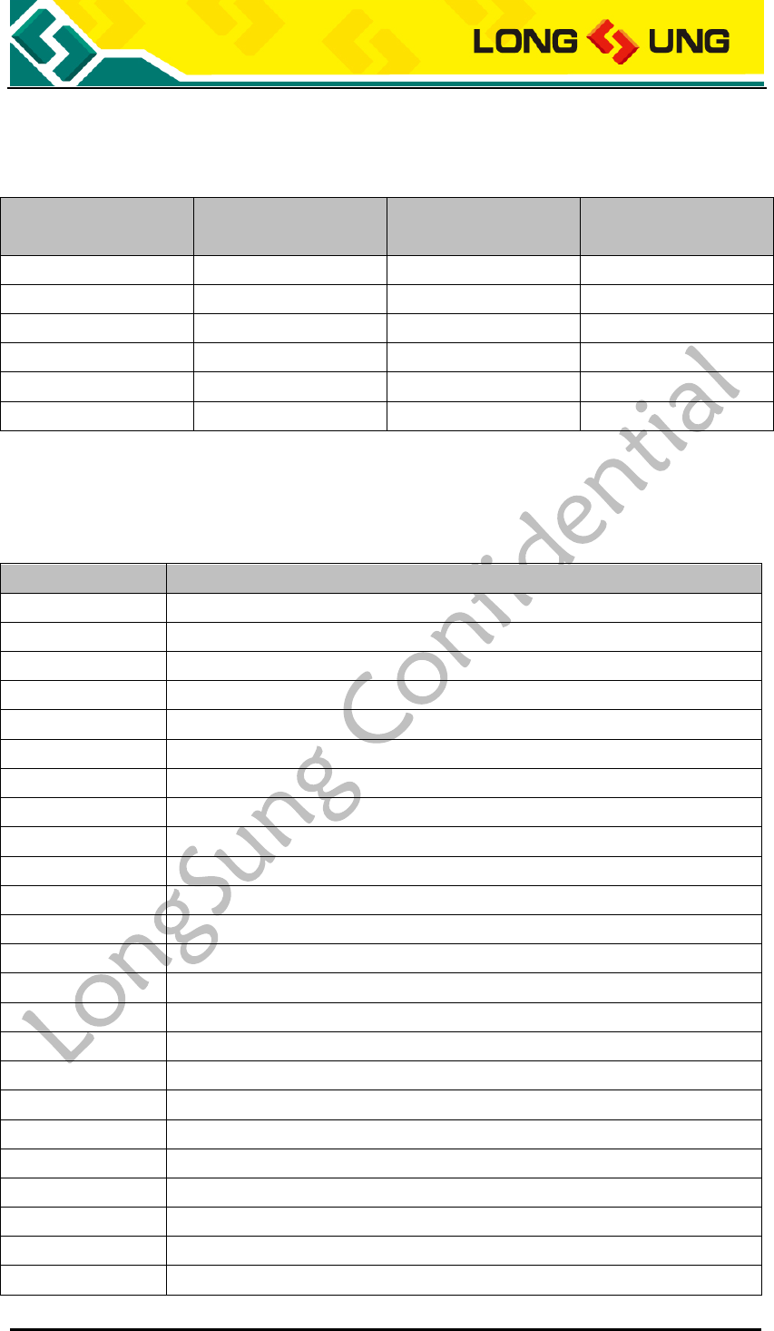
1.4. Document’s history
Table1:Document’s update history
Version
Name
Date
Update
description
V2.0
Huaming Zhang
2012-10-24
V2.0 version create
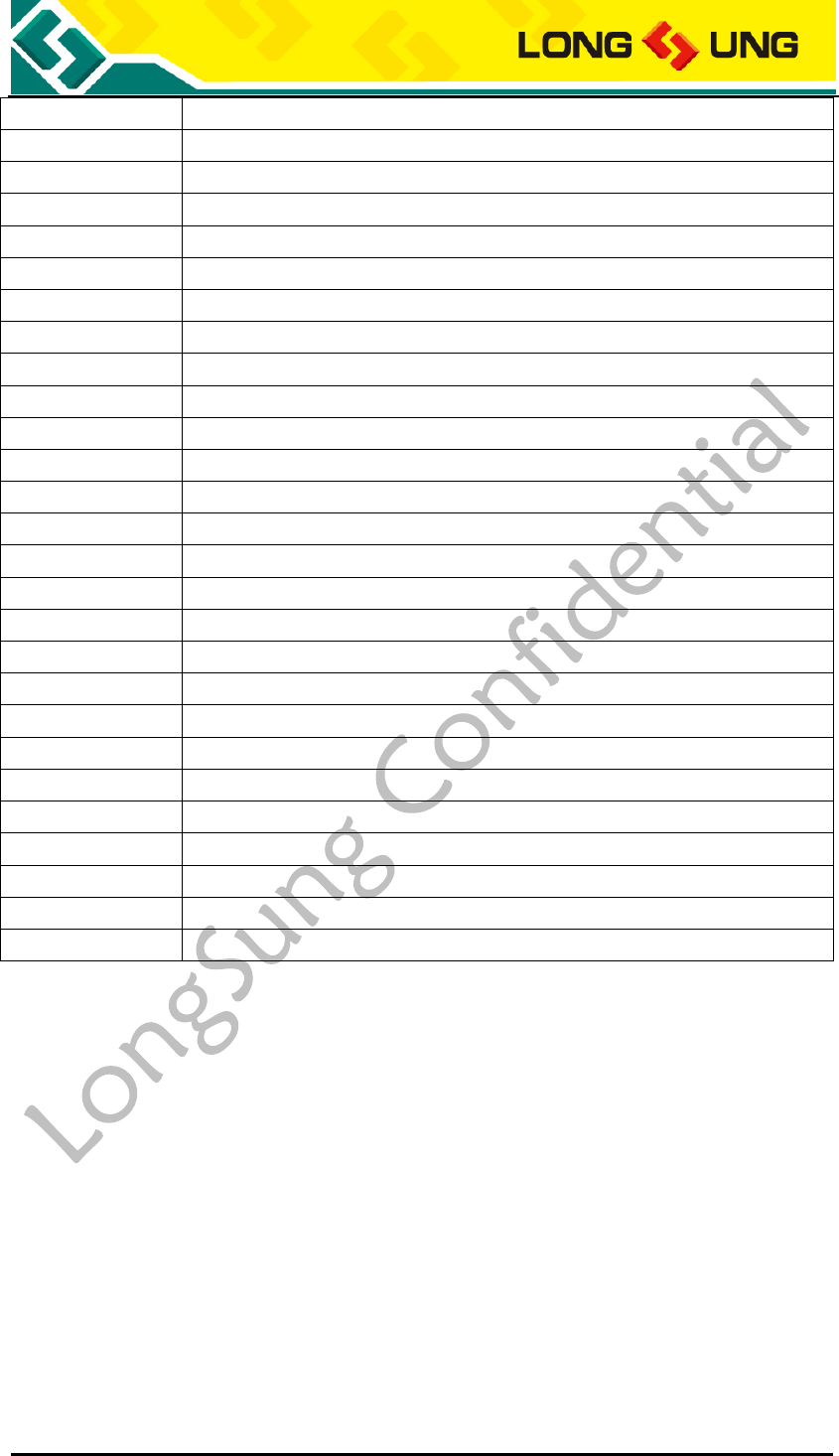
1.5. Abbreviations
Table2:Abbreviation and description
Abbreviations
Description
AMR
Adaptive Multi-rate
BER
Bit Error Rate
BTS
Base Transceiver Station
PCI
Peripheral Component Interconnect
CS
Circuit Switched (CS) domain
CSD
Circuit Switched Data
DCE
Data communication equipment
DTE
Data terminal equipment
DTR
Data Terminal Ready
EDGE
Enhanced Data rates for GSM Evolution
EFR
Enhanced Full Rate
EGSM
Enhanced GSM
EMC
Electromagnetic Compatibility
ESD
Electrostatic Discharge
FR
Frame Relay
GMSK
Gaussian Minimum Shift Keying
GPIO
General Purpose Input Output
GPRS
General Packet Radio Service
GSM
Global Standard for Mobile Communications
HR
Half Rate
HSDPA
High Speed Downlink Packet Access
HSUPA
High Speed Uplink Packet Access
HSPA
HSPA High-Speed Packet Access
IEC
International Electro-technical Commission
U3500_Hardware_User_Guide _V2.0 Page 11 of 82
IMEI
International Mobile Equipment Identity
I/O
Input/Output
ISO
International Standards Organization
ITU
International Telecommunications Union
bps
bits per second
LED
Light Emitting Diode
M2M
Machine to machine
MO
Mobile Originated
MT
Mobile Terminated
NTC
Negative Temperature Coefficient
PC
Personal Computer
PCB
Printed Circuit Board
PCS
Personal Cellular System
PCI
Peripheral Component Interconnect
PCM
Pulse Code Modulation
PCS
Personal Communication System
PDU
Packet Data Unit
PPP
Point-to-point protocol
PS
Packet Switched
QPSK
Quadrate Phase Shift Keying
SIM
Subscriber Identity Module
TCP/IP
Transmission Control Protocol/ Internet Protocol
UART
Universal asynchronous receiver-transmitter
USIM
Universal Subscriber Identity Module
UMTS
Universal Mobile Telecommunications System
USB
Universal Serial Bus
WCDMA
Wideband Code Division Multiple Access

U3500_Hardware_User_Guide _V2.0 Page 12 of 82
2. Introduction
U3500 is a wireless module which is designed for the global market. It is a
consumptive product; it can be designed in many kinds of applications which
can work on UMTS/EDGE/GPRS/GSM network.
U3500 support the Bands as the following:
Dual-Band UMTS(WCDMA/FDD): 850/2100 MHz;
Quad-Band GSM :850/900/DCS1800/PCS1900 MHz。
U3500 integrates the RF and Baseband onto one small PCB. It can fulfill all the
functions of RF signal receiving and transmitting, Baseband signal processing
and audio signal processing so that the customers can realize all kinds of their
own wireless products with very few peripheral components.
Designed on a single-side PCB, U3500 has a tiny dimension of
36.0mm×32.0mm×2.75mm, with a LGA pad, which provides all hardware
interfaces between the module and customers’ boards. The main hardware
interfaces of U3500 consist of power supply interfaces, USB interface, UART
interfaces, USIM/SIM interface, Audio interfaces, PCM interface, ADC interface,
VRTC interface and GPIO.
U3500 is integrated with the TCP/IP protocol, it not only supports standard AT
(Complied with Hayes 3GPP TS 27.007 and 27.005), but also support Longsung
extended AT commands, which are very suited for developing all kinds of the
customized applications.
U3500 provide main interfaces for applications, the interfaces as the
following:
1) Power interface
2) USB interface
3) UART interface
4) USIM/SIM interface
5) Analog audio interface
6) PCM interface
7) ADC interface
8) GPIO
9) RESET input interface
10) POWER_ON interface
11) PWM interface;

U3500_Hardware_User_Guide _V2.0 Page 13 of 82
12) RTC inteface
13) IIC inteface
14) Camera inteface
15) SD inteface
16) VCHG inteface
17) Voltage output
18) Antenna inteface
U3500_Hardware_User_Guide _V2.0 Page 14 of 82
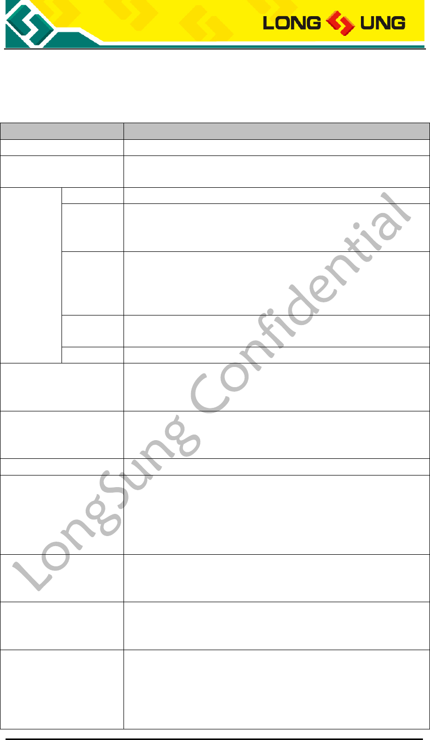
2.1. Key features
Table3:Key features of U3500
Feature
Description
Power supply
3.5V~4.2V (Typical 3.8V)
Frequency Bands
UMTS: Dual-Band, 850/2100MHz
EDGE/GPRS/GSM: Quad-Band, 850/900/1800/1900MHz
Data
UMTS
UMTS PS: 384 kbps(DL), 384 kbps(UL)
EDGE
EDGE: Class12, 236.8kbps(DL), 118kbps(UL)
Mobile station class B
Coding schemes: MCS1-9
GPRS
GPRS: Class12,85.6kbps(DL),42.8kbps(UL)
Mobile station class B
Coding schemes: CS1-4
Support Full PBCCH
CSD
UMTS CSD:57.6kbps
GSM CSD:14.4kbps
Special
Integrated with the TCP/IP Protocol
Voice(Optional)
Triple-rate codec for HR, FR and EFR
GSM & 3GPP: Adaptive multi-rate (AMR)
Support DTMF
SMS
Point-to-point MO and MT
SMS cell broadcast
Support Text and PDU mode
MMS
Need AP achieve MMS Protocol
Video Phone
Need external CODEC;
Video format H.263; Audio format G.723.1;
AP achieve H.324M Protocol;
H.245 Control Protocol for reliable transmission
H.223 for multiplexing/de-multiplexing Protocol
Operation temperature
Normal operation: -20℃~+65℃
Restricted Operation: -30℃~+75℃
Storage temperature: -40℃~+85℃
ESD
VBAT, GND: Air discharge ±8KV,Contact discharge ±4KV
RF interface: Air discharge ±8KV,Contact discharge ±4KV
Else ports: Air discharge ±4KV, Contact discharge±2KV
Max power RF transition
Class 4 (2 W) for GSM850/GSM900
Class 1 (1 W) for GSM1800/GSM1900
Class E2 (0.5 W) for EDGE900
Class E2 (0.4 W) for EDGE1800
Class 3 (0.25 W) for UMTS

U3500_Hardware_User_Guide _V2.0 Page 15 of 82
Current consumption
Off mode: 50μA
Sleep mode: <4mA
Idle mode: <40mA
Voice mode: <300mA
Data mode: <600mA
Connector
Stamp hole PAD
LGA PAD
Stamp hole PAD
Power interface
1 USB2.0 High-Speed interface
1 UART interface(can be used as GPIO)
1 standard USIM/SIM interface (Support 3V&1.8V
USIM/SIM)
1 USIM/SIM detect GPIO
1 analog audio channel
1 PCM interface(can be used as GPIO)
1 hardware Reset
1 ADC interface
1 NETLIGHT interface
3 voltage output(2.6V, 1.8V, 1.5~3.05 adjustable)
1 power on interface
1 VRTC
3 GPIO
1 IIC interface
1 Camera interface
1 SD interface
1 VCHG interface
1 LCD backlight driver
3 sleep and awake GPIO
Antenna interface
LGA PAD
1 LCD interface(Reserved)
1 5×5 keypad interface(Reserved)
1 bluetooth 32KHz clock output(Reserved)
1 ADC interface(Reserved)
1 analog audio channel(Reserved)
Dimensions
36.0mm×32.0mm×2.75mm
Weight
<8g
Fixed structure
Stamp hole PAD and LGA PAD
Test points
8 test points:
JTAG interface
AT command
Standard AT commands (Hayes 3GPP TS 27.007 and 27.005)
Support LongSung Extend AT commands
Approvals
RoHS
U3500_Hardware_User_Guide _V2.0 Page 16 of 82
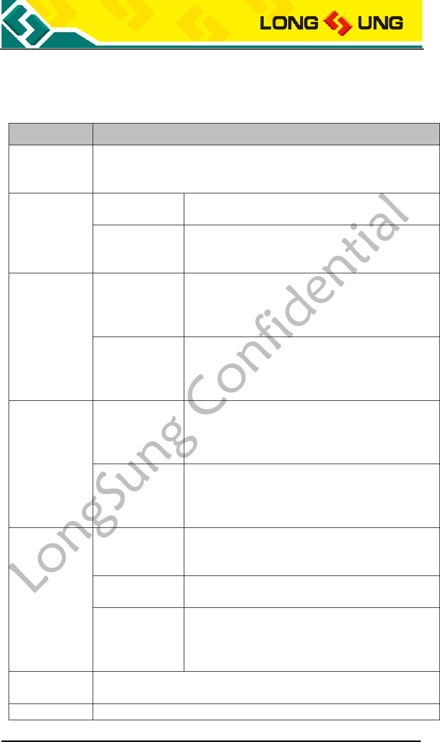
2.2. Operating modes
Table4:Overview operating modes
Mode
Function
Sleep mode
Refer to the method of chapter 3.4.4.1, the module will reduce to minimal
level.
GSM mode
GSM IDLE
Software is active. Module has registered to the GSM
network, and the module is ready to send and receive.
GSM TALK
Connection is going on between two subscribers. In
this case, the power consumption depends on network
settings.
GPRS mode
GPRS IDLE
Module is ready for GPRS data transfer, but no data is
currently sent or received. Power consumption
depends on network settings and GPRS configuration
(e.g. multi-slot settings).
GPRS DATA
GPRS data transfer in progress. Power consumption
depends on network settings (e.g. power control
level), uplink/downlink data rates and GPRS
configuration (e.g. used multi-slot settings).
GPRS mode
EDGE IDLE
Module is ready for EDGE data transfer, but no data is
currently sent or received. Power consumption
depends on network settings and EDGE configuration
(e.g. multi-slot settings).
EDGE DATA
EDGE data transfer in progress. Power consumption
depends on network settings (e.g. power control
level), uplink/downlink data rates and EDGE
configuration (e.g. used multi-slot settings).
WCDMA mode
WCDMA IDLE
Software is active. Module has registered to the
WCDMA network, and the module is ready to send and
receive.
WCDMA TALK
Module is serving in audio. The power consumption
depends on WCDMA network settings.
WCDMA DATA
WCDMA data transfer in progress. Power consumption
depends on network settings (e.g. power control
level), uplink/downlink data rates and WCDMA
configuration.
Minimum
Function mode
VBAT remains applied.
Use AT+CFUN=0 to let module go into Minimum Function mode
Power Down
Module will go to power off mode when use AT+POWEROFF or VBAT to low.
U3500_Hardware_User_Guide _V2.0 Page 17 of 82
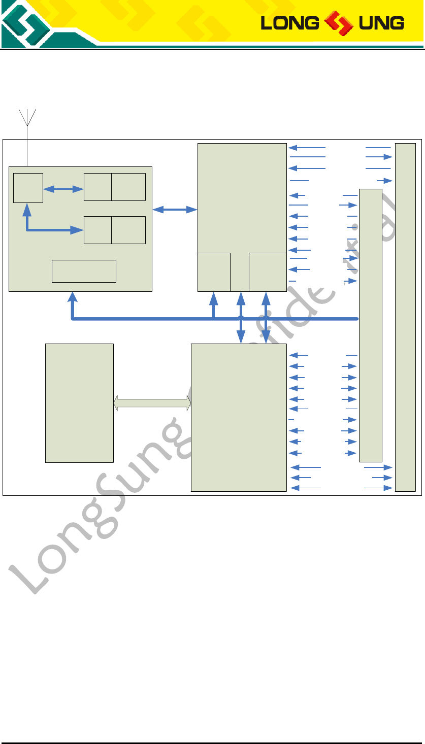
2.3. Hardware functional block diagram
ABB
PMU Audio
SW WCDMA
TRX
PA
GSM
TRX
PA
RF
VCTCXO
DDR FLASH
&SDRAM DBB
Stamp hole pad
(
83-pin: J101- J183
)
VBAT
RESET
USB
USIM
PCM
UART
RESET
NETLIGHT
GPIO
SD
LDO
PowerOn
VRTC
ADC
VCHG
LCD Backlight
LGA (74-pin: J201 -J274)
Speaker
MIC2
MIC1
Receiver
ADC
32.768K BT clock
Camera
Keypad
LCD
Keypad Backlight
Reset
Figure1:U3500 Hardware functional block diagram
☆RF include:
1) WCDMA Transceiver
2) GSM Transceiver
3) SW
4) VCTCXO
☆Analog Baseband include:
1) PMU
2) Audio process unit
☆Digital Baseband include:
1) Digital Baseband chip
2) NAND FLASH and SDRAM
U3500_Hardware_User_Guide _V2.0 Page 18 of 82
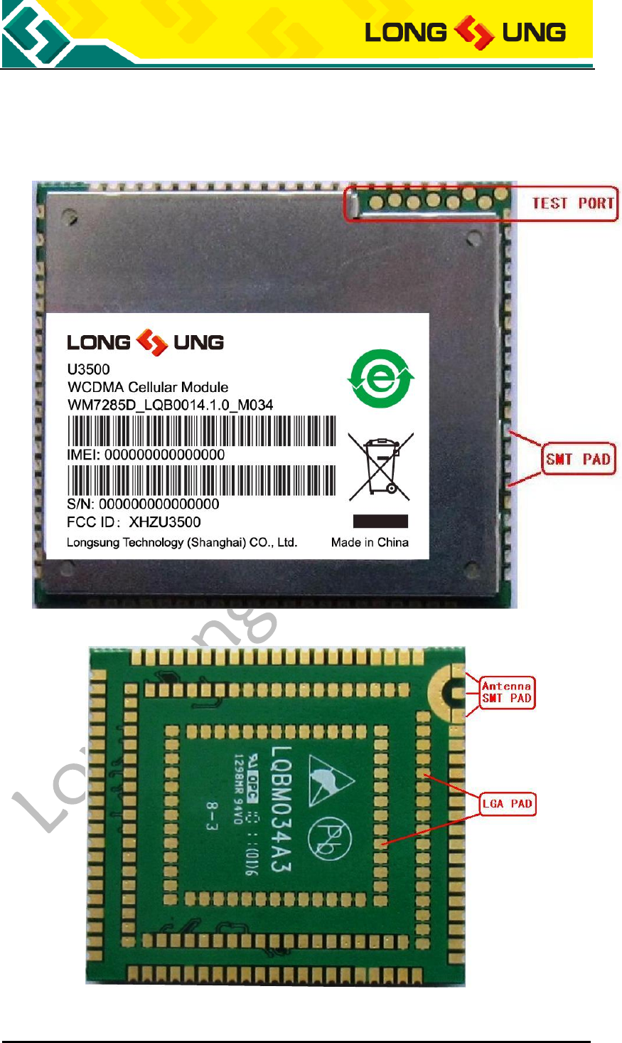
2.4. Hardware interface
U3500 is a Single-side Layout PCBA.
Figure2:U3500 top view
Figure3:U3500 bottom view

U3500_Hardware_User_Guide _V2.0 Page 19 of 82
U3500 hardware interfaces include: 1 group Test points, an antenna RF
connector, a 83-pin stamp hole PAD, a groups LGA PAD.
One group Test points: As figure 2 signed “TEST PORT”.
JTAG debug test points is used when module in abnormal for downloading
firmware and debug module. It is only for RD engineers.
RF interface: As figure 3 signed “Antenna SMT PAD”.
Stamp hole antenna SMT PAD is welded in customer mainboard directly, this
interface can solder an antenna with impedance of 50Ω.
83-pin stamp hole SMT PAD: As figure 2 signed “SMT PAD”.
This group provide abundant of interface, the details are describe in chapter
3.
126-pin LGA PAD: As figure 3 signed”LGA PAD”.
This group is reserved, default is NC.
U3500_Hardware_User_Guide _V2.0 Page 20 of 82
3. Application interfaces description
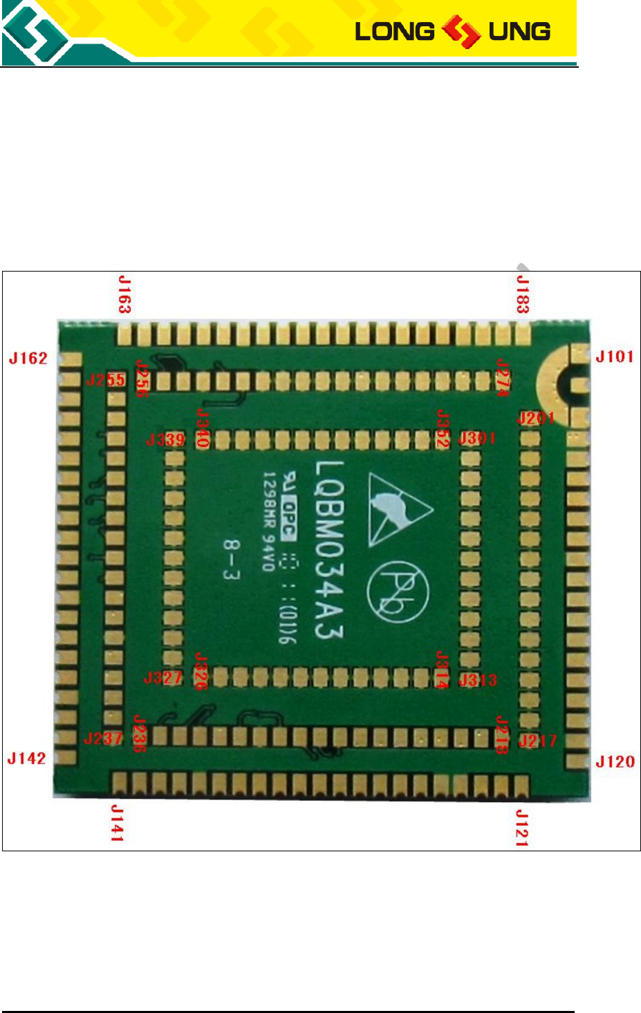
3.1. 83-pin Stamp hole SMT PAD and 126-pin
LGA PAD
Figure4:U3500 83-pin stamp hole SMT PAD and 126-pin LGA PAD pin
location

U3500_Hardware_User_Guide _V2.0 Page 21 of 82
Table5:U3500 pin definition
83-pin stamp hole SMT PAD
PIN NO.
PIN Name
I/O
Describe
J101
GND
J102
ANT
Antenna interface
J103
GND
J104
GND
J105
GND
J106
AP_RDY
I
AP awaked and ready for communication
J107
AP_IRQ
I
AP require BP to sleep
J108
BP_IRQ
0
BP require AP to awake
J109
USIM_DET
I
USIM/SIM card detect
J110
GND
J111
PCM_SYNC
O
PCM interface, can be used as GPIO
J112
PCM_DOUT
O
PCM interface, can be used as GPIO
J113
PCM_DIN
I
PCM interface, can be used as GPIO
J114
PCM_CLK
I
PCM interface, can be used as GPIO
J115
NETLIGHT
O
The GPIO default is NETLIGHT
J116
I2C_SDA
I/O
Serial interface data input and output
J117
I2C_SCL
O
Serial interface clock output
J118
LCD_DRV_N
O
LCD backlight
J119
GND
J120
ADC0
2.6V, ADC
J121
VREG_GP2
O
1.5~3.05V adjustable voltage output
J122
VREG_MSME
O
1.8V voltage output
J123
VOUT
O
2.6V voltage output
J124
GND
J125
GND
J126
VBAT
I
3.5~4.2V, typical 3.8V
J127
VBAT
I
3.5~4.2V, typical 3.8V
J128
VBAT
I
3.5~4.2V, typical 3.8V
J129
VCHG
O
4.5~7.0V, typical 5.0V
J130
VREG_MMC
O
2.6V, the power supply for SD card
J131
SDCC1_DATA0
I/O
SD Interface, can be used as GPIO
J132
SDCC1_DATA1
I/O
SD Interface, can be used as GPIO
J133
SDCC1_DATA2
I/O
SD Interface, can be used as GPIO
J134
SDCC1_DATA3
I/O
SD Interface, can be used as GPIO
J135
SDCC1_CLK
O
SD Interface, can be used as GPIO
J136
SDCC1_CMD
O
SD Interface, can be used as GPIO
J137
GND
J138
USIM_CLK
O
1.8/3.0V

U3500_Hardware_User_Guide _V2.0 Page 22 of 82
PIN NO.
PIN Name
I/O
Describe
J139
USIM_RESET
O
1.8/3.0V
J140
USIM_DATA
I/O
1.8/3.0V
J141
USIM_VCC
O
1.8/3.0V
J142
USB_VBUS
I
5.0V
J143
USB_DM
I/O
USB Data-
J144
USB_DP
I/O
USB Data+
J145
GND
J146
SPK_N
O
Loudspeaker cathode
J147
SPK_P
O
Loudspeaker anode
J148
MIC2_N
I
200mVpp(2.6Vpp,Max)
J149
MIC2_P
I
200mVpp(2.6Vpp,Max)
J150
GND
J151
CAMIF_DATA0
O
Bit 0 of RGB or YUV D0 video output
J152
CAMIF_DATA1
O
Bit 1 of RGB or YUV D1 video output
J153
CAMIF_DATA2
O
Bit 2 of RGB or YUV D2 video output
J154
CAMIF_DATA3
O
Bit 3 of RGB or YUV D3 video output
J155
CAMIF_DATA4
O
Bit 4 of RGB or YUV D4 video output
J156
CAMIF_DATA5
O
Bit 5 of RGB or YUV D5 video output
J157
CAMIF_DATA6
O
Bit 6 of RGB or YUV D6 video output
J158
CAMIF_DATA7
O
Bit 7 of RGB or YUV D7 video output
J159
CAMIF_DATA8
O
Bit 8 of RGB or YUV D8 video output
J160
CAMIF_DATA9
O
Bit 9 of RGB or YUV D9 video output
J161
CAMIF_PCLK
O
Pixel clock output
J162
GND
J163
CAMIF_MCLK
I
Master clock input
J164
GND
J165
CAMIF_HSYNC
O
Video horizontal line synchronization signal
J166
CAMIF_VSYNC
O
Vertical sync output
J167
CAMIF_RESET
O
Master reset input, active low
J168
CAMIF_EN
O
Vidio enable
J169
GND
J170
VRTC
I
1.5~3.25V, typical 3.0V
J171
POWER_ON
I
4.2V(Active low)
J172
RESET
I
2.6V(Active low)
J173
UART_TX
O
UART_TX, can be used as GPIO
J174
UART_RX
I
UART_RX, can be used as GPIO
J175
UART_CTS
I
UART_CTS, can be used as GPIO
J176
UART_RTS
O
UART_RTS, can be used as GPIO
J177
UART_DTR
I
UART_DTR, can be used as GPIO
J178
UART_DCD
O
UART_DCD, can be used as GPIO
J179
UART_RI
O
UART_RI, can be used as GPIO

U3500_Hardware_User_Guide _V2.0 Page 23 of 82
PIN NO.
PIN Name
I/O
Describe
J180
GND
J181
GND
J182
GND
J183
GND
74-pin LGA PAD
PIN NO.
PIN Name
I/O
Describe
J201
GND
J202
GND
J203
GND
J204
GND
J205
GND
J206
GND
J207
GND
J208
GND
J209
GND
J210
GND
J211
GND
J212
GND
J213
GND
J214
GND
J215
GND
J216
GND
J217
GND
J218
GND
J219
KEYOUT4
O
Keypad interface
J220
KEYOUT3
O
Keypad interface
J221
KEYOUT3
O
Keypad interface
J222
KEYOUT1
O
Keypad interface
J223
KEYOUT0
O
Keypad interface
J224
KEYSENSE_N4
I
Keypad interface
J225
KEYSENSE_N3
I
Keypad interface
J226
KEYSENSE_N2
I
Keypad interface
J227
KEYSENSE_N1
I
Keypad interface
J228
KEYSENSE_N0
I
Keypad interface
J229
KPD_DRV_N
O
Keypad backlight
J230
GND
J231
LCD_RESET
O
LCD interface
J232
LCD_CS
O
LCD interface
J233
LCD_RS
O
LCD interface
J234
LCD_WR
O
LCD interface

U3500_Hardware_User_Guide _V2.0 Page 24 of 82
PIN NO.
PIN Name
I/O
Describe
J235
LCD_RD
O
LCD interface
J236
GND
J237
GND
J238
EARON
O
80mVpp(4.26Vpp,Max)
J239
EAROP
O
80mVpp(4.26Vpp,Max)
J240
MIC_N
I
200mVpp(2.6Vpp,Max)
J241
MIC_P
I
200mVpp(2.6Vpp,Max)
J242
GND
J243
LCD_DB15
O
LCD interface
J244
LCD_DB14
O
LCD interface
J245
LCD_DB13
O
LCD interface
J246
LCD_DB12
O
LCD interface
J247
LCD_DB11
O
LCD interface
J248
LCD_DB10
O
LCD interface
J249
LCD_DB09
O
LCD interface
J250
LCD_DB08
O
LCD interface
J251
LCD_DB07
O
LCD interface
J252
LCD_DB06
O
LCD interface
J253
LCD_DB05
O
LCD interface
J254
LCD_DB04
O
LCD interface
J255
LCD_DB03
O
LCD interface
J256
LCD_DB02
O
LCD interface
J257
LCD_DB01
O
LCD interface
J258
LCD_DB00
O
LCD interface
J259
GND
J260
32K_CLK_BT
O
32KHz clock for Bluetooth
J261
ADC1
I
2.6V, ADC
J262
GND
J263
GND
J264
GND
J265
GND
J266
GND
J267
GND
J268
GND
J269
GND
J270
GND
J271
GND
J272
GND
J273
GND
J274
GND

U3500_Hardware_User_Guide _V2.0 Page 25 of 82
52-pin LGA PAD
PIN NO.
PIN Name
I/O
Describe
J301
GND
J302
GND
J303
GND
J304
GND
J305
GND
J306
GND
J307
GND
J308
GND
J309
GND
J310
GND
J311
GND
J312
GND
J313
GND
J314
GND
J315
GND
J316
GND
J317
GND
J318
GND
J319
GND
J320
GND
J321
GND
J322
GND
J323
GND
J324
GND
J325
GND
J326
GND
J327
GND
J328
GND
J329
GND
J330
GND
J331
GND
J332
GND
J333
GND
J334
GND
J335
GND
J336
GND
J337
GND
J338
GND
J339
GND
U3500_Hardware_User_Guide _V2.0 Page 26 of 82
PIN NO.
PIN Name
I/O
Describe
J340
GND
J341
GND
J342
GND
J343
GND
J344
GND
J345
GND
J346
GND
J347
GND
J348
GND
J349
GND
J350
GND
J351
GND
J352
GND
U3500_Hardware_User_Guide _V2.0 Page 27 of 82
3.2. Power supply
U3500 power on and power off correlative interfaces as the following:
Table6:U3500 Power supply correlative interfaces
PIN Name
I/O
PIN Num.
Description
VBAT
I
J126, J127, J128
Power supply, 3.5~4.2V, typical
3.8V
VRTC
I
J170
1.5~3.25V, typical 3.0V
VOUT
O
J123
Voltage output, 2.6V, 80mA
VREG_GP2
O
J121
Adjustabe voltage output 1.5V
to3.05V
VREG_MSME
O
J122
Voltage output, 1.8V
VREG_MMC
O
J130
SD interface power supply
POWER_ON
I
J171
Power on, 4.2V, Low active
RESET
I
J172
Reset, 2.6V, Low active
VCHG
O
J129
Li-on battery charger interface
4.5~4.7V
GND
J101, J103~105, J110, J119,
J124~125, J137, J145, J150,
J162, J164, J169, J180~183,
J201~218, J230, J236~237,
J242, J259, J262~274,
J301~352
GND
3.2.1. Power Supply and reference design
3.2.1.1. VBAT input
The power supply of U3500 should be a single voltage source with VBAT ranged
from 3.5V to 4.2V. As a mobile terminal conformed to the HSPA/UTMS/GSM
criterions, in some case, the ripple in a transmit burst may cause a maximum
voltage drop of 450mV while the current consumption will rise to the typical
peak of 2A. So the power supply must be able to provide sufficient current.
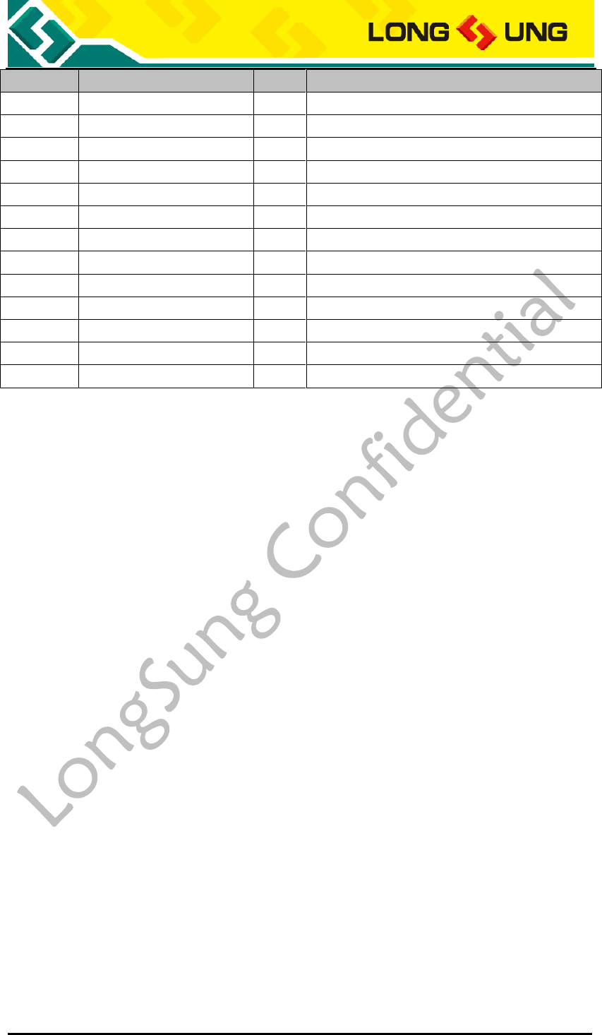
The capacitor must be a larger one electrolytic capacity (recommend
2200uF/10V) or two smaller dimension tantalum capacities (470uF/6.3V) in
parallel (CA) is recommended. And with a small (0.1 µF to 1µF) ceramic (CB) in
parallel; the capacitors should put as close as possible to the U3500 VBAT pins.
U3500_Hardware_User_Guide _V2.0 Page 28 of 82
VBAT
CACB
+
Figure5:U3500 VBAT input
3.2.1.2. VRTC input
PINJ170 of U3500 module is VRTC interface.
VRTC can be used for connecting backup rechargeable battery. When VBAT
power supply is not available, the battery supplies the power to RTC core of
U3500. When VBAT is available, U3500 can recharge the battery via VRTC pin.
If the RTC is useless for you, you can set PINJ170 as NC.
Reference design as the following:
VRTC
U3500
RTC Core
Rechargeable battery
Figure6:VRTC connect to rechargeable battery
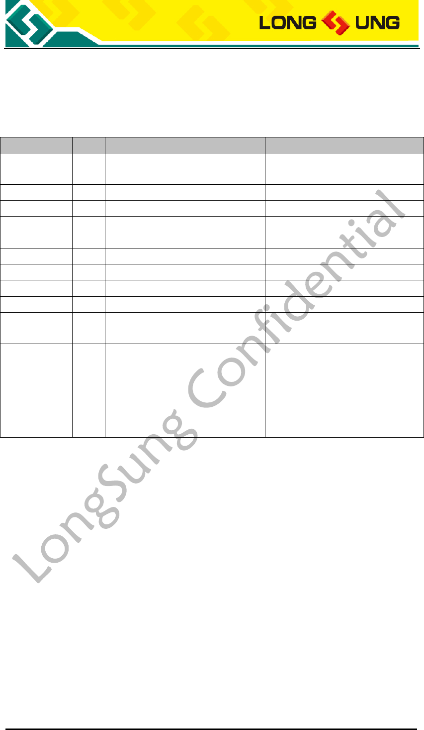
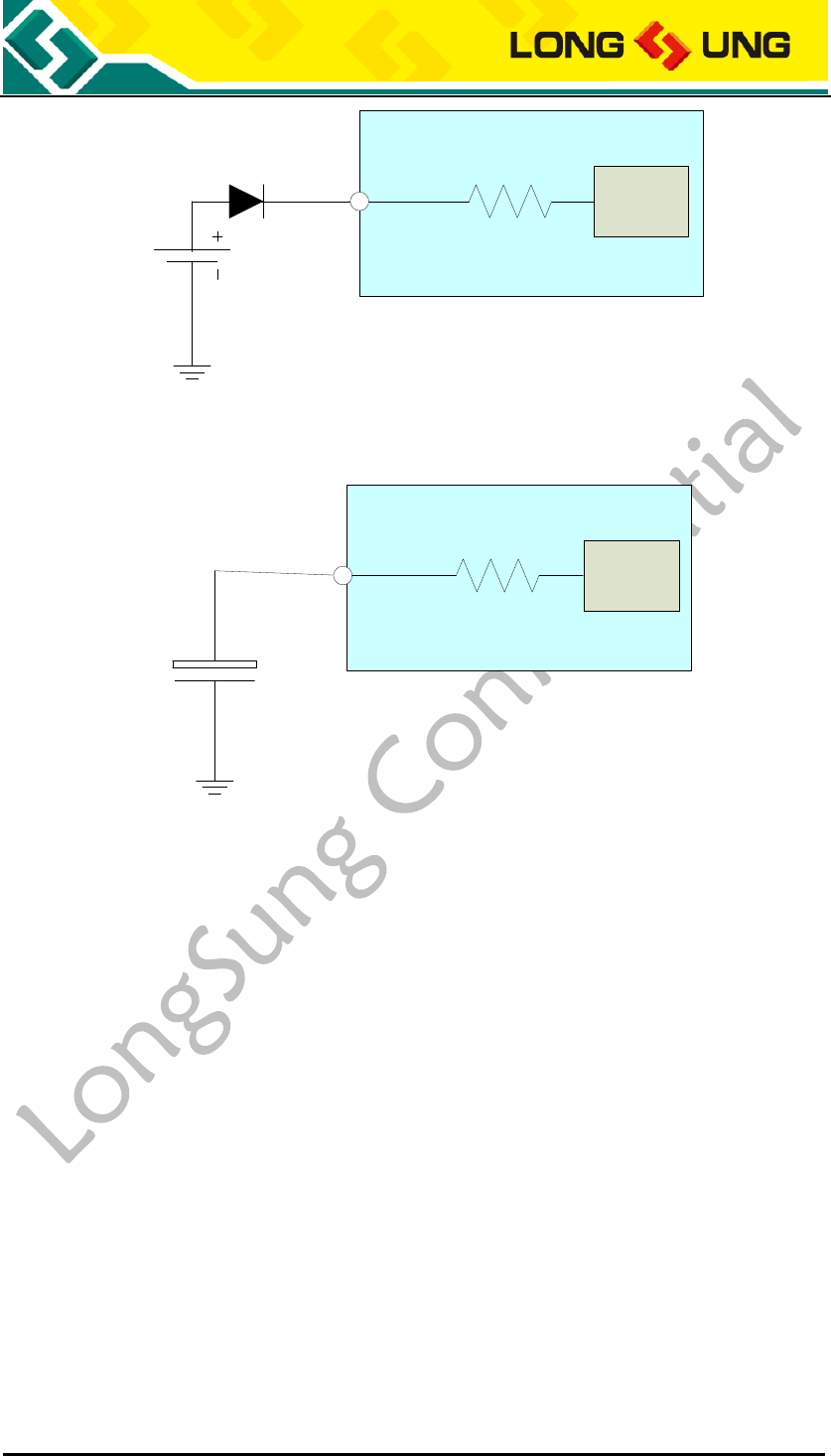
If use non-rechargeable battery, the reference design as the following:
U3500_Hardware_User_Guide _V2.0 Page 29 of 82
VRTC
U3500
Non-rechargeable battery
RTC Core
Figure7:VRTC connect to non-rechargeable battery
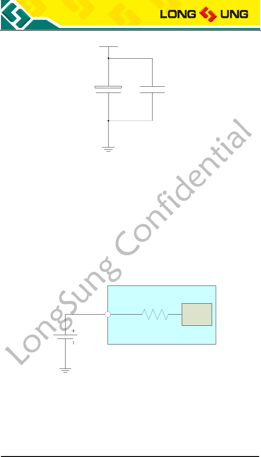
If use a large capacitance capacity, the reference design as the following:
VRTC
Large-capacitance capacitor
+
U3500
RTC Core
Figure8:VRTC connect to large capacitance capacity
3.2.1.3. VOUT、VREG_GP2、VREG_MMC voltage output
During U3500 working, 2.6V voltage will output through PINJ123 of U3500, it
named VOUT. The current is rated for 80mA. VOUT can be used as a power
supply of the external device, such as LCD. And you can read the level of VOUT
to judge whether the module is working.
Besides, U3500 also provides a adjustable voltage output named VREG_GP2
through PINJ121, the range of voltage is 1.5V to 3.05V.
U3500 can support SD interface, and provide a voltage VREG_MMC for it
through PINJ130.
3.2.1.4. POWER_ON input
The POWER_ON (PINJ171) is used to control U3500 power on. When the VBAT
U3500_Hardware_User_Guide _V2.0 Page 30 of 82
is active, POWER_ON can control U3500 to power on
If connect POWER_ON to GND in application, U3500 power on mode will be
VBAT active power on mode. When VBAT is active, the module will be power
on automatically. In this mode, U3500 just can be power down with VBAT
set to low or off.
If application can control POWER_ON high or low level, During VBAT is
active, first set POWER_ON to low level with 1000mS, U3500 will be power
on.
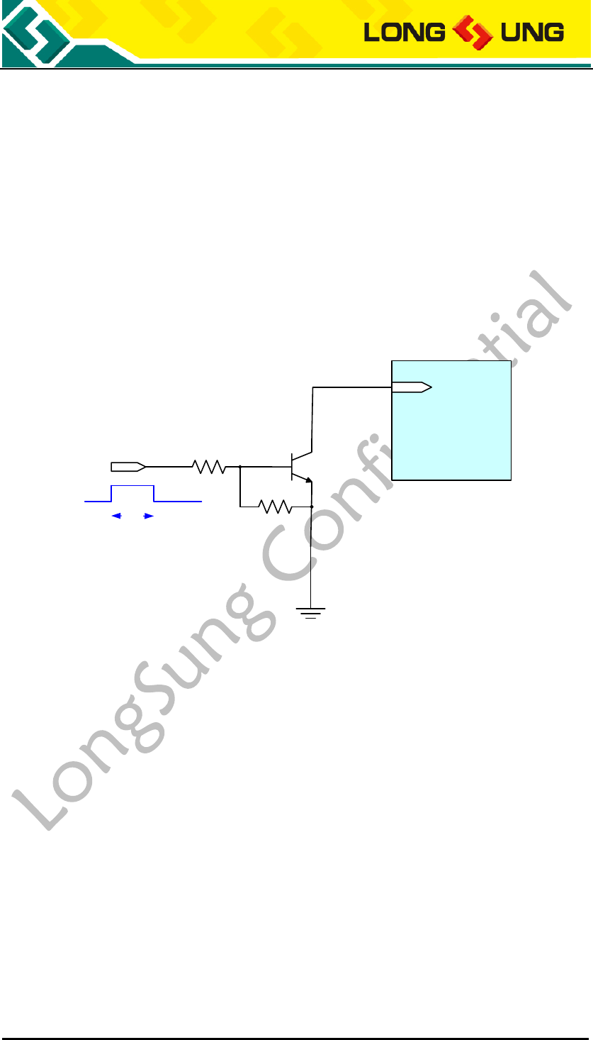
The section reference design of POWER_ON input as the figure below. The
AP_PWR_CTRL is the control signal of application; it can control U3500 to
power on.
U3500
J171
AP_PWR_CTRL
POWER_ON
Ton
Figure9:POWER_ON control module power on
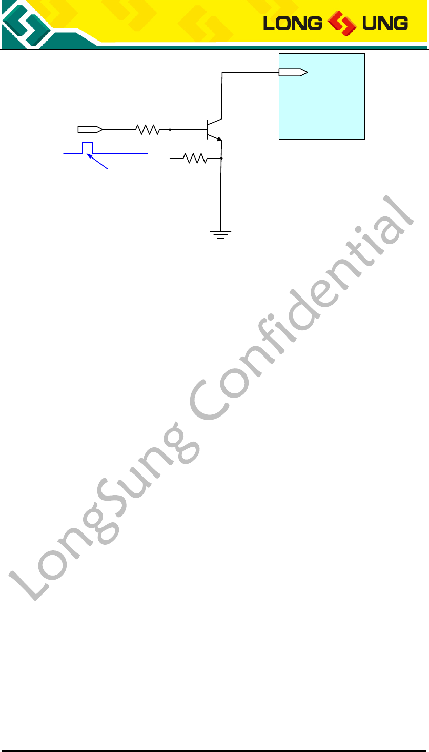
3.2.1.5. RESET input
The RESET (PINJ172) can control U3500 module to reset. The RESET is active
by low level.
A low level pulse with 100mS will be used when set module reset.
The part of RESET reference design as the figure below. AP_RESET is the control
signal from the application.
U3500_Hardware_User_Guide _V2.0 Page 31 of 82
U5300
J172
AP_RESET
RESET
Tst
Figure10:AP_RESET control module reset
3.2.2. Power on/off control
There are two methods to power on the module U3500: VBAT active power on,
POWR_ON control power on. The method depends on the external circuit of the
application (POWER_ON input circuit).
There are two methods to power off the module U3500: AT command to power
off, VBAT set to low or off.
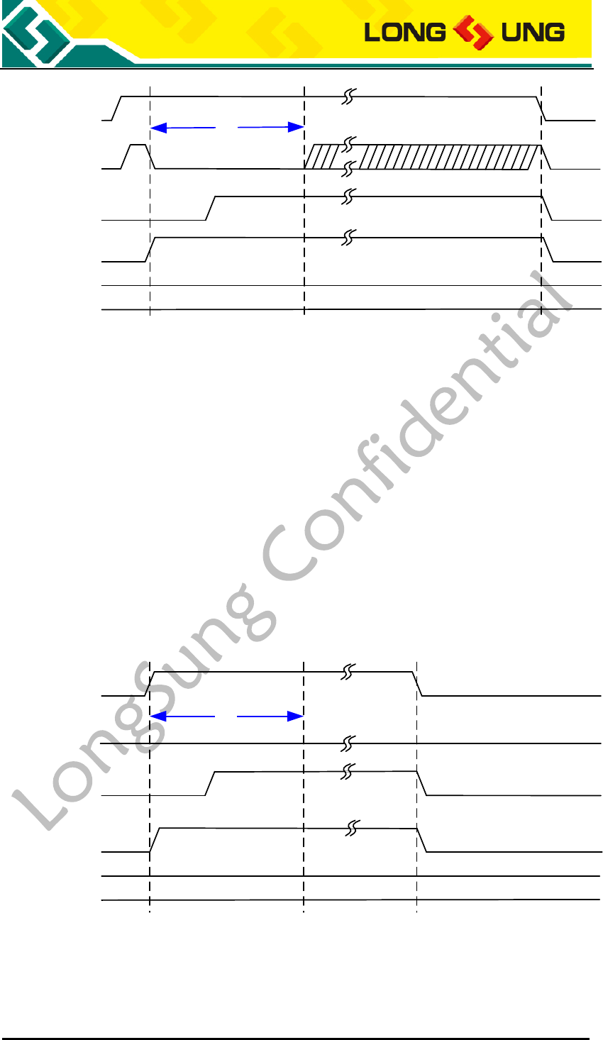
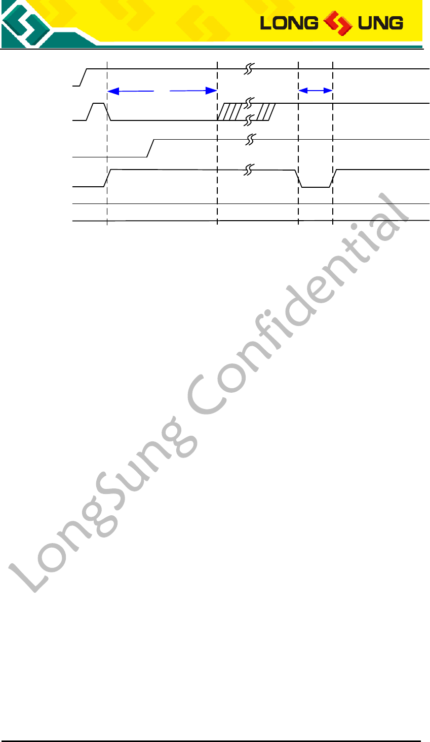
3.2.2.1. POWER_ON control module power on
Insure that the power supply of U3500 VBAT is active (3.5~4.2V, typical
3.8V).The POWER_ON must be controlled. The power on timing is as the figure
below.
Note: The POWER_ON must be controlled. In this method the module
can be power off by AT command and set VBAT to low or off.
U3500_Hardware_User_Guide _V2.0 Page 32 of 82
VBAT
POWER_ON
VOUT
Module State OFF Power-on sequence
Ton
ON OFF
RESET
Figure11:POWER_ON control module power on timing
The Ton is 1000mS.
3.2.2.2. VBAT active power on
Insure that the power supply of U3500 VBAT is active (3.5~4.2V, typical
3.8V).When connect POWER_ON to GND, U3500 will be VBAT active power on
mode.
Note: When module is VBAT active power on mode, module only can be
power off by VBAT set low or off.
VBAT
POWER_ON
VOUT
Module State OFF Power-on sequence
Ton
ON OFF
Low
RESET
Figure12:VBAT active power on mode timing
U3500_Hardware_User_Guide _V2.0 Page 33 of 82
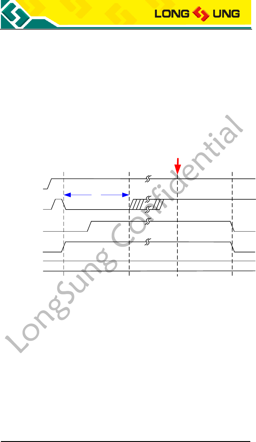
3.2.2.3. AT command power off
Only when module is POWER_ON control power on mode, U3500 can use AT
command to power off. When module is working, and POWER_ON is high level,
use AT command can let U3500 power off.
Power off AT command as the following:
AT+POWEROFF
AT command power off timing as the figure below:
VBAT
POWER_ON
VOUT
Module State OFF Power-on sequence
Ton
ON Power-off sequence OFF
AT+POWEROFF
RESET
Figure13:AT command power off timing
3.2.2.4. VBAT set low or off to power off mode
When the power supply of U3500 VBAT is too low (include VBAT is off), the
module will be power off.
3.2.3. RESET control
Control RESET (PINJ139) to set U3500 reset. The RESET is active by low level.
The RESET signal must be a Tst (100mS) low pulse. Send AT+RESET can reset
the U3500 too.
U3500_Hardware_User_Guide _V2.0 Page 34 of 82
VBAT
POWER_ON
VOUT
Module State OFF Power-on sequence
Ton
ON RESET ON
RESET
Tst
Figure14:U3500 RESET timing

U3500_Hardware_User_Guide _V2.0 Page 35 of 82
3.3. USB interface
3.3.1. USB interface description
U3500 module supports a USB2.0 High-Speed interface. U3500 default PID is
0X9603. When the USB drivers of U3500 are installed, the OS will detect 3
virtual serial ports: Modem port, Diagnostic port, AT port.
Table7:U3500 USB interface
PIN Name
I/O
PIN Num.
Description
USB_VBUS
I
J142
USB power supply, 5V
USB_DM
I/O
J143
USB data-
USB_DP
I/O
J144
USB data+
GND
J101, J103~105, J110, J119,
J124~125, J137, J145, J150,
J162, J164, J169, J180~183,
J201~218, J230, J236~237,
J242, J259, J262~274,
J301~352
GND
3.3.2. USB reference circuit
The USB part reference design circuit as the figure below.
U3500_Hardware_User_Guide _V2.0 Page 36 of 82
U3500
C2
33pF C1
10uF
R1 10R
R2 10R
USB_VBUS
USB_DM
USB_DP
USB_VBUS
DM
DP
GND
1
2
3
4
65
USBBF
ESD
ESD
ESD
Figure15:U3500 USB interface reference design circuit
1) To get the reliable USB power supply, it is recommended to use a 10uF (C1)
filter capacitor and a 33pF (C2) filter capacitor. DC rated voltage of the
capacitors should be above 10V;
2) To reduce the reflection caused by the high frequency alternating signal in
the transmission, it is recommended to add a resistor with value below 10Ω
to the DM and DP in USB interface to ensure correct transmission for USB
data. Just like the resistors R1and R2;
3) To avoid static electricity in USB interface, it is recommended to use the ESD
protection device. Junction capacitance of the ESD component should be
less than 5pF;
4) To get the reliable USB data transfer, need protect the USB device. Such as
must protect the USB_DP, USB_DM, need 90Ω impedance control, and let

U3500_Hardware_User_Guide _V2.0 Page 37 of 82
them keep away from the interference signal.
3.3.3. USB driver
U3500 module support many kinds of OS, such as: Windows 2000, Windows XP,
Windows Vista32/64, Windows 7, Windows CE5.0/6.0, Windows Mobile5.0/6.0.
When use these systems, need special drivers for U3500.
For different OS and VID and PID, the drivers are different. If need them, please
contact with FAE of LongSung. The default VID and PID is: VID_1C9E &
PID_9603.
For Linux OS, such as Radhat, Ubuntu and Android, need the OS itself USB
driver usbserial.ko. You need load the driver usbserial.ko and PID, VID to the
system.
3.3.3.1. Linux OS load USB driver for U3500
Make sure there is usbserial.ko driver in your Linux system. Linux2.4.X and
Linux2.6.X OS have usbserial.ko, but for some Ubuntu editions must recompile
the kernel to get the usbserial.ko.
The following is in PC Linux2.6.X OS load driver process. (Note: Embed Linux
OS may have some difference)
1) Please insert U3500 to the AP with Linux system by USB. And make sure the
power supply for U3500 is active and steady and can power on U3500;
2) Preparation of lookup USB devices by Linux usbfs filesystem, mount the
USB filesystem, type the command like this:
#mount -t usbfs none /proc/bus/usb
3) Check the status of AP device, in order to make sure AP is ready, we can

U3500_Hardware_User_Guide _V2.0 Page 38 of 82
type command like this:
#cat /proc/bus/usb/devices
Then we will get the result as the following:
T: Bus=03 Lev=01 Prnt=01 Port=00 Cnt=01 Dev#=9 Spd=12 MxCh= 0
D: Ver= 1.10 Cls=00(>ifc ) Sub=00 Prot=00 MxPS=64 #Cfgs= 1
P: Vendor=1c9e ProdID=9603 Rev= 0.00
S: Manufacturer=Qualcomm, Incorporated
S: Product=Qualcomm CDMA Technologies MSM
C:* #Ifs= 5 Cfg#= 1 Atr=a0 MxPwr=500mA
I:* If#= 0 Alt= 0 #EPs= 3 Cls=ff(vend.) Sub=ff Prot=ff Driver=(none)
E: Ad=81(I) Atr=03(Int.) MxPS= 16 Ivl=128ms
E: Ad=82(I) Atr=02(Bulk) MxPS= 64 Ivl=0ms
E: Ad=02(O) Atr=02(Bulk) MxPS= 64 Ivl=0ms
I:* If#= 1 Alt= 0 #EPs= 2 Cls=ff(vend.) Sub=ff Prot=ff Driver=(none)
E: Ad=84(I) Atr=02(Bulk) MxPS= 64 Ivl=0ms
E: Ad=04(O) Atr=02(Bulk) MxPS= 64 Ivl=0ms
I:* If#= 2 Alt= 0 #EPs= 2 Cls=ff(vend.) Sub=ff Prot=ff Driver=(none)
E: Ad=86(I) Atr=02(Bulk) MxPS= 64 Ivl=0ms
E: Ad=06(O) Atr=02(Bulk) MxPS= 64 Ivl=0ms
If the USB device is ready, we can see the red characters listed above. From
it, the vendor ID and product ID is 1c9e and 9603. Like Vendor=1c9e
ProdID=9603 Rev= 0.00.
Also, we can see three serial ports displayed by blue characters. They are
diagnostic port, AT port and modem port (The ports from the top to the
bottom should be like this: DIAG, AT, MODEM).
4) Install USB drivers in AP, type command like this:
#modprobe usbserial vendor=0x1c9e product=0x9603
5) Check the status of device driver, type command like this:
#cat /proc/bus/usb/devices

U3500_Hardware_User_Guide _V2.0 Page 39 of 82
You my get the result as the following:
T: Bus=03 Lev=01 Prnt=01 Port=00 Cnt=01 Dev#=3 Spd=12 MxCh= 0
D: Ver= 1.10 Cls=00(>ifc ) Sub=00 Prot=00 MxPS=64 #Cfgs=1
P: Vendor=1c9e ProdID=9603 Rev= 0.00
S: Manufacturer=Qualcomm, Incorporated
S: Product=Qualcomm CDMA Technologies MSM
C:* #Ifs= 5 Cfg#= 1 Atr=a0 MxPwr=500mA
I:* If#= 0 Alt= 0 #EPs= 3 Cls=ff(vend.) Sub=ff Prot=ff Driver=usbserial_generic
E: Ad=81(I) Atr=03(Int.) MxPS= 16 Ivl=128ms
E: Ad=82(I) Atr=02(Bulk) MxPS= 64 Ivl=0ms
E: Ad=02(O) Atr=02(Bulk) MxPS= 64 Ivl=0ms
I:* If#= 1 Alt= 0 #EPs= 2 Cls=ff(vend.) Sub=ff Prot=ff Driver=usbserial_generic
E: Ad=84(I) Atr=02(Bulk) MxPS= 64 Ivl=0ms
E: Ad=04(O) Atr=02(Bulk) MxPS= 64 Ivl=0ms
I:* If#= 2 Alt= 0 #EPs= 2 Cls=ff(vend.) Sub=ff Prot=ff Driver=usbserial_generic
E: Ad=86(I) Atr=02(Bulk) MxPS= 64 Ivl=0ms
E: Ad=06(O) Atr=02(Bulk) MxPS= 64 Ivl=0ms
If the driver is ready, we can see the usbserial_generic on the right side of
each port.
6) Check the device point in the /dev filesystem:
#cd /dev
# ls ttyUSB*
If the AP driver is OK, there should be ttyUSB0~ ttyUSB2.
3.3.3.2. Linux OS AP use AT to control U3500
1) Please insert the USIM/SIM card into the application terminal, make sure
the USIM/SIM card with Data service already been permitted. Plug the
WCDMA/GSM antenna to RF connector of U3500. Power on the module

U3500_Hardware_User_Guide _V2.0 Page 40 of 82
U3500, load the USB driver, create USB end ports: ttyUSB0~ ttyUSB2.
2) Run minicom application in Linux OS:
#minicom –s
In the menu of minicom select “Serial port setup”, set “Serial device ” as
/dev/ttyUSB1 (Note: AT(ttyUSB1), Modem(ttyUSB2) can response AT
commands, Diag (ttyUSB0) can not response AT commands); Then
back to the menu of minicom and select “Save setup as df1 ”, save the
configuration, then select “exit ” to exit minicom.
3) Send AT commands by minicom
#minicom
It should prompt as the following:
Welcome to minicom 2.3 OPTIONS: I18n
Compiled on Feb 24 2008, 16:35:15. Port /dev/ttyUSB1
Press CTRL-A Z for help on special keys
Input AT command to open the echo of AT:
ATE
IF the system is running normally, it should prompt as the following:
OK
Input AT command to get the version of firmware:
AT+LCTSW
Will get the following response:
SoftwareVersion: LQA0082.2.3_MG24
InnerVersion: LQA0082_240085_6.0.8W1215_EFS1.5
OK
Input AT command to get the strength and BER:
AT+CSQ
Will get the following response:
+CSQ: 20,74

U3500_Hardware_User_Guide _V2.0 Page 41 of 82
OK
Input AT command to get the status of registration:
AT+CREG?
Will get the following response:
+CREG: 0,1
OK
Input AT command to get the information operator:
AT+COPS?
Will get the following response:
+COPS: 0,0,"CHN-CUGSM",2
OK
3.3.3.2. Linux OS AP dial PPP connection
1) Repeat loading USB driver and AT communication with U3500. Make
sure U3500 get the normal registration, and the strength of RF signal
will be stronger than 13 (The first parameter of CSQ).
2) Make sure the Linux OS has pppd application, if it hasn’t pppd
application, please install kppp, you will get pppd in your OS.
3) Create a new file: /etc/ppp/chat/gprs-connect-chat
Then add messages as the following:
TIMEOUT 15
ABORT "DELAYED"
ABORT "BUSY"
ABORT "ERROR"
ABORT "NO DIALTONE"

U3500_Hardware_User_Guide _V2.0 Page 42 of 82
ABORT "NO CARRIER"
TIMEOUT 40
'' \rAT
OK ATS0=0
OK ATE0V1
OK AT+CGDCONT=1,"IP","3GNET"
OK ATDT*99***1#
CONNECT ''
Note: Different USIM/SIM card which you insert in the
application terminal, AT+CGDCONT=1,"IP","3GNET" will be
different. Please contact the operator to get the APN and replace
the parameter "3GNET".
4) Modify the configuration of pppd: /etc/ppp/options
If you find the “auth”, modify it as “#auth”. The result is there aren’t ID
verification.
5) Create a new file: /etc/ppp/peer/gprs
Add messages as the following: (The end port must be ttyUSB2):
# Usage: root>pppd call gprs
/dev/ttyUSB2
9600
crtscts
modem
#noauth
debug
nodetach
#hide-password
usepeerdns
noipdefault
defaultroute

U3500_Hardware_User_Guide _V2.0 Page 43 of 82
user "3gnet"
0.0.0.0:0.0.0.0
ipcp-accept-local
ipcp-accept-remote
#lcp-echo-failure 12
#lcp-echo-interval 3
#noccp
#novj
#novjccomp
#persist
connect '/usr/sbin/chat -s -v -f /etc/ppp/chat/gprs-connect-chat'
6) Connect to the Internet:
#pppd call gprs
# ifconfig
If you get the ppp0 net port means that PPP is successful.
eth0 Link encap:Ethernet HWaddr 00:1D:09:33:A7:E1
inet addr:172.16.180.105 Bcast:172.16.180.255 Mask:255.255.255.0 inet6
addr: fe80::21d:9ff:fe33:a7e1/64 Scope:Link UP BROADCAST RUNNING
MULTICAST MTU:1500 Metric:1 RX packets:39793 errors:0 dropped:0
overruns:0 frame:0 TX packets:17971 errors:0 dropped:0 overruns:0 carrier:0
collisions:0 txqueuelen:1000 RX bytes:3445057 (3.2 MiB) TX bytes:20088925
(19.1 MiB) Interrupt:169 lo Link encap:Local Loopback inet addr:127.0.0.1
Mask:255.0.0.0 inet6 addr: ::1/128 Scope:Host UP LOOPBACK RUNNING
MTU:16436 Metric:1 RX packets:20 errors:0 dropped:0 overruns:0 frame:0 TX
packets:20 errors:0 dropped:0 overruns:0 carrier:0 collisions:0 txqueuelen:0
RX bytes:1160 (1.1 KiB) TX bytes:1160 (1.1 KiB)
ppp0 Link encap:Point-to-Point Protocol inet addr:10.182.207.113
P-t-P:10.64.64.64 Mask:255.255.255.255 UP POINTOPOINT RUNNING NOARP
MULTICAST MTU:1500 Metric:1 RX packets:5 errors:0 dropped:0 overruns:0
U3500_Hardware_User_Guide _V2.0 Page 44 of 82
frame:0 TX packets:6 errors:0 dropped:0 overruns:0 carrier:0 collisions:0
txqueuelen:3 RX bytes:62 (62.0 b) TX bytes:101 (101.0 b)
7) Testing the Internet
# ping 119.75.217.56
It is the IP address of www.baidu.com. If the ping fails, we need add a
route like this:
#route add default gw 10.64.64.64
Note: 10.64.64.64 is the ISP address as the red character above.
# ping www.baidu.com
If ping www.baidu.com fails, we should add DNS to the /etc/resolv.conf
8) Disconnect the internet
# killall pppd
3.4. UART interface
U3500 module provides a UART interface.
3.4.1. UART interface description
Table8:U3500 UART interface
PIN Name
I/O
PIN Num.
Description
UART_RX
I
J174
RX in UART
UART_TX
O
J173
TX in UART
UART_CTS
I
J175
CTS in UART
UART_RTS
O
J176
RTS in UART
GND
J101, J103~105, J110, J119,
J124~125, J137, J145, J150, J162,
J164, J169, J180~183, J201~218,
J230, J236~237, J242, J259,
J262~274, J301~352
GND
3.4.2. UART interface reference circuit
For an application system, U3500 uses as DCE (Data Communication Equipment)
U3500_Hardware_User_Guide _V2.0 Page 45 of 82
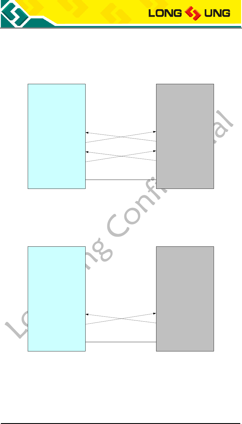
and application terminal uses as DTE (Data terminal equipment).
If AP will use U3500 UART port as data transfer mode, the recommended
DCE-DTE connection as the figure below:
U3500(DCE) HOST(DTE)
UART_CTS
UART_RTS
UART_RX
UART_TX
DCD
DTR
DSR
CTS
RTS
RX
TX
RI
GND GND
Figure16:U3500 UART is used for data transfer
If AP will use U3500 UART port as AT commands mode, the recommended
DCE-DTE connection as the figure below:
U3500(DCE) HOST(DTE)
UART_CTS
UART_RTS
UART_RX
UART_TX
DCD
DTR
DSR
CTS
RTS
RX
TX
RI
GND GND
Figure17:U3500 UART is used for AT command
3.4.3. UART interface description
1) DATA_RTS/DATA_CTS are the hardware flow control signal, the connection
should be crossed as figure 16;
U3500_Hardware_User_Guide _V2.0 Page 46 of 82
2) The baud rate of UART can be set as: 300, 600, 1200, 2400, 4800, 9600,
19200, 38400, 57600, 115200,230400, 460800, 921600, 3200000,
3686400, 4000000;
Baud rate can be set by AT command. The AT command is:
AT+IPR=<value>
<value>:
300, 600, 1200, 2400, 4800, 9600, 19200, 38400, 57600, 115200,230400
Note: The default baud rate is 115200, and Data Bits=8,
Parity=None, Stop Bits=1, Flow Control=None.
3) As the UART interface can only supply TTL level while the PC serial port is
RS232 level. Level conversion device (e.g. SP3238EEA) is needed when
U3500 communicating with PC;
4) It is recommended that UART interface needs ESD protect.
3.4.4. U3500 sleep and awake control
In order to describe easily, it is named U3500 as BP and the MCU of application
terminal as AP.
Sleep and awake interface is descripted in the table below:
Table9:U3500 sleep and awake interface
PIN Name
I/O
PIN Num.
描述
AP_IRQ
I
J107
Set it to high, BP will sleep.
BP_IRQ
O
J108
BP request AP to awake, set low
level with 120mS.
AP_RDY
I
J106
AP is ready, active is low level.
UART_RX
I
J174
Set it to high level with 100mS
will awake BP.
USB_VBUS
I
J142
4.4~5.25V, typical is 5V
USB_DM
I/O
J143
USB D-
USB_DP
I/O
J144
USBD+
GND
J101, J103~105, J110, J119,
J124~125, J137, J145, J150,
J162, J164, J169, J180~183,
J201~218, J230, J236~237,
J242, J259, J262~274,
J301~352
GND

U3500_Hardware_User_Guide _V2.0 Page 47 of 82
3.4.4.1. The prerequisites for module to sleep
There are 3 prerequisites for module to fall asleep, lack of any of which will
cause the module unable to sleep:
1) The AP_IRQ pin is high (AP_IRQ pin is high by default when it is float);
2) UART _RX pin is kept low (UART _Rx is low by default when it is float);
3) USB is suspended by AP (if USB is not used, the prerequisites are two of the
above).
3.4.4.2. About sleep and awake questions
Due to the connection mode of BP and AP, may face some questions:
1) USB is not connected, nor is UART
Q: How can the module fall asleep and awake up?
A: The module can not fall asleep in this mode.
2) Only UART is connected
Q: How can the module fall asleep and awake up?
A: The module is enabled to sleep by setting the AP_IRQ high and the
UART_RX to low, and is disabled to sleep by setting the AP_IRQ low or the
UART_RX to high.
Note: When the module receives a call/SMS/MMS/Video call, it
will wake up automatically.
3) Only USB is connected
Q: How can the module fall asleep and awake up?
A: The module is enabled to sleep by setting the AP_IRQ high, and is
disabled to sleep by setting the AP_IRQ low.
The USB driver can make the USB suspend by setting the
PORT_SUSPEND property, and make the USB resume by clear the
PORT_SUSPEND property.
The USB status (suspend resume) and the AP_IRQ status (high low) can
decide the module sleep mode.
Note: When the module receives a call/SMS/MMS/Video call, it
will wake up automatically.
4) USB and UART are all connected
Q: How can the module fall asleep?
A:AP_IRQ is high and put low the UART _RX PIN and suspend the USB.

U3500_Hardware_User_Guide _V2.0 Page 48 of 82
Q: How can the module wake up?
A: AP_IRQ is low and put high the UART _RX PIN and resume the USB.
Q:How does the USB driver suspend and resume the USB in LINUX?
A:The usbserial of the linux2.6.XX can make the USB suspend by sysfs
filesystem, If the USB has been suspended, the module can suspend
automatically.
Q: How does the USB driver suspend and resume the USB in WINCE?
A: On wince operating system, 3G module can suspend/resume by setting
USB bus power level.
When AP_IRQ pin is high, AP sets USB bus D4/D0 power level, then 3G
module go into suspend/resume mode.
When AP sets USB bus D4, 3G module enters sleep mode and USB cdc
driver stop to send/receive data.
If 3G module is waked up by coming call, you must set USB bus D0 power
level to notify USB cdc driver to start to send/receive data, after getting
BP_IRQ signal.
Q: How does the module wake up AP?
A: When the module awake, it will send a BP_IRQ signal (a LOW pulse of
120ms duration) to wake up the AP. If the AP is ready, it will set the
AP_RDY active low to tell the module that AP is ready to communicate
with the module; if the AP is not ready yet, the module will store the
message into buffer until the number of the message is up to 32 and
discard the message wherefrom.
Note:AP_RDY must be connected, either to GND, or to AP.
U3500_Hardware_User_Guide _V2.0 Page 49 of 82
3.5. Analog audio interface
U3500 provide two channels analog audio interface.
3.5.1. Audio interface description
Table10:U3500 analog audio interface
PIN Name
I/O
PIN Num.
Description
SPK_N
O
J146
Loudspeaker output differential signal -
SPK_P
O
J147
Loudspeaker output differential signal +
MIC2_N
I
J148
Audio input channel 2 differential signal -
MIC2_P
I
J149
Audio input channel 2 differential signal +
EARON
O
J238
Audio output channel 1 differential signal -
EAROP
O
J239
Audio output channel 1 differential signal +
MIC_N
I
J240
Audio input channel 1 differential signal -
MIC_P
I
J241
Audio input channel 1 differential signal +
3.5.2. Audio I/O and earphone connection
Table11:The connection between earphone jack and audio I/O
PIN Name
PIN Num.
Earphone
jack
Description
EARON
J238
Left Speaker
Audio output channel 1 differential signal -
EAROP
J239
Right Speaker
Audio output channel 1 differential signal +
MIC_N
J240
MIC
Audio input channel 1 differential signal -
MIC_P
J241
PGND
Audio input channel 1 differential signal +
3.5.3. Audio I/O and phone handfree
connection
Table12:The connection between phone handle and audio I/O
PIN Name
PIN Num.
Phone
handfree
Description
SPK_N
J146
SPK_N
Loudspeaker output differential signal -
SPK_P
J147
SPK_P
Loudspeaker output differential signal +
MIC2_N
J148
MIC_N
Audio input channel 2 differential signal -
U3500_Hardware_User_Guide _V2.0 Page 50 of 82
MIC2_P
J149
MIC_P
Audio input channel 2 differential signal +
3.5.4. Audio I/O and phone handset
connection
Table13:U3500 analog audio and handset connection
PIN Name
PIN Num.
Phone
handset
Description
EAROP
J238
EAR_N
Audio output channel 1 differential signal -
EARON
J239
EAR_P
Audio output channel 1 differential signal +
MIC_P
J240
MIC_N
Audio input channel 1 differential signal -
MIC_N
J241
MIC_P
Audio input channel 1 differential signal +
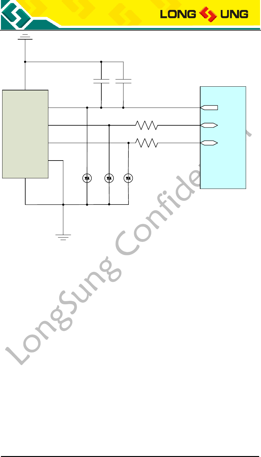
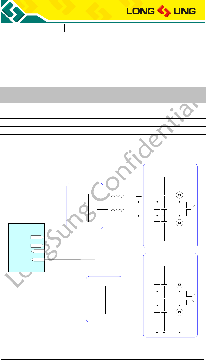
3.5.5. Analog audio interface reference circuit
10pF 33pF
ESD
10pF 33pF
10pF 33pF ESD
Differential Layout
Close to Speaker
10pF 33pF
ESD
10pF 33pF
10pF 33pF ESD
Differential Layout
Close to MIC
MIC_P/MIC2_P
MIC_N/MIC2_N
EAROP/SPK_P
EARON/SPK_N
U3500
BEAD
BEAD
1nF
1nF
Figure18:Analog audio interface reference circuit

U3500_Hardware_User_Guide _V2.0 Page 51 of 82
1) The audio output signals, a pair of differential signals, output to two
speakers. The output signals are not real stereo signals which are different
from traditional stereo sound.
2) It is recommended to use the filter capacitor or filter circuit to reduce inter
frequency interference and improve audio quality. Just like what is shown in
the figure above.
3) To avoid static electricity, it is recommended to use the ESD protection
device.
4) It requires connecting audio analog signal ground with the general digital
circuit ground, magnetic bead or zero ohm resistance can be used.
5) IF use an audio amplifier for speaker, optional EMI filtering is shown at
Fogure19, these components (two ferrite beads and two capacitors) can be
added to reduce electromagnetic interference. If used, they should be
located near the EAROP and EARON.
6) Considerable current between the audio output pins and the speaker, the
width of PCB traces are recommended: MIC 8mils, Speaker 12mils.
3.6. PCM interface
U3500 module provides a PCM interface. The PCM include 4 pin digital signals.
Use PCM interface can support communication between U3500 and external
CODEC. These 4 pin signals can also be used as GPIO.
PCM TX data will be routed from the external codec MIC through the DSP encode
path in the U3500 module. PCM RX data will be routed through the DSP decode
path to the external codec speaker.
The base band of U3500 can be used in two modes:
1) Auxiliary PCM, the auxiliary PCM that runs at 128 kHz and uses a 62.5 μs
sync pulse (half a time frame).
2) Primary PCM, the primary PCM that runs at 2.048 MHz and uses 488 ns sync
pulse (one 2.048 MHz clock tick).
U3500_Hardware_User_Guide _V2.0 Page 52 of 82
Table14:Auxiliary PCM and Primary PCM configuration
Configuration
SYNC
CLK
Clock source
Format
Auxiliary
8KHz
128KHz
Master
8Bits μ-law,
8Bits A-law,
16Bits Linear (13 bits
are valid, the others
are blank)
Primary
8KHz
2.048MHz
Master/Slave
The default configuration of U3500 is Primary PCM, and can use AT command to
select Master Mode or Slave Mode.
In Master mode, the U3500 module drives the clock and sync signals that are
sent to the external codec via the PCM interface.
In Slave mode, the external codec drives the clock and sync signals that are
sent to the U3500 module.
The AT command for Select PCM Master and Slave mode:
AT+PCMCONFIG =<value>
<value>:
0:default Master mode
1:change to Slave mode
U3500 module supports 3 PCM formats: 8Bits μ-law, 8Bits A-law, 16Bits
(Linear), can be set by AT command:
The AT command for set PCM formats:
AT+PCMAUDIO=<value>
<value>:
0:default inner channel
1:change the channel to PCM 16 bit linear
2:change the channel to PCM 8 bit μ-law
3:change the channel to PCM 8 bit A-law
3.6.1. PCM interface description
Table15:U3500 PCM interface
PIN Name
I/O
PIN Num.
Description
PCM_SYNC
O
J111
PCM Synchronous Signal
PCM_CLK
I
J114
PCM CLK
PCM_DIN
I
J113
PCM Input
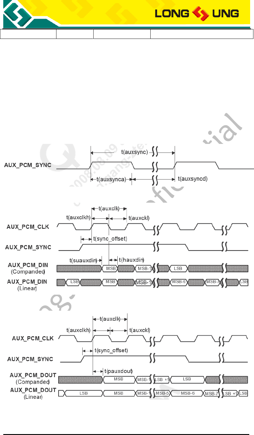
U3500_Hardware_User_Guide _V2.0 Page 53 of 82
PCM_DOUT
O
J112
PCM Output
3.6.2. Auxiliary PCM
The Auxiliary PCM interface enables communication with an external codec to
support hands-free applications. The auxiliary codec port operates with
standard long-sync timing and a 128 kHz clock. The AUX_PCM_SYNC runs at 8
kHz with a 50% duty cycle. Most μ-law and A-law codecs support the 128 kHz
AUX_PCM_CLK bit clock.
Figure19:AUX_PCM_SYNC timing
Figure20:AUX_PCM_CODEC to U3500 timing
Figure21:U3500 to AUX_PCM_CODEC timing
Table16:AUX_CODEC timing parameters
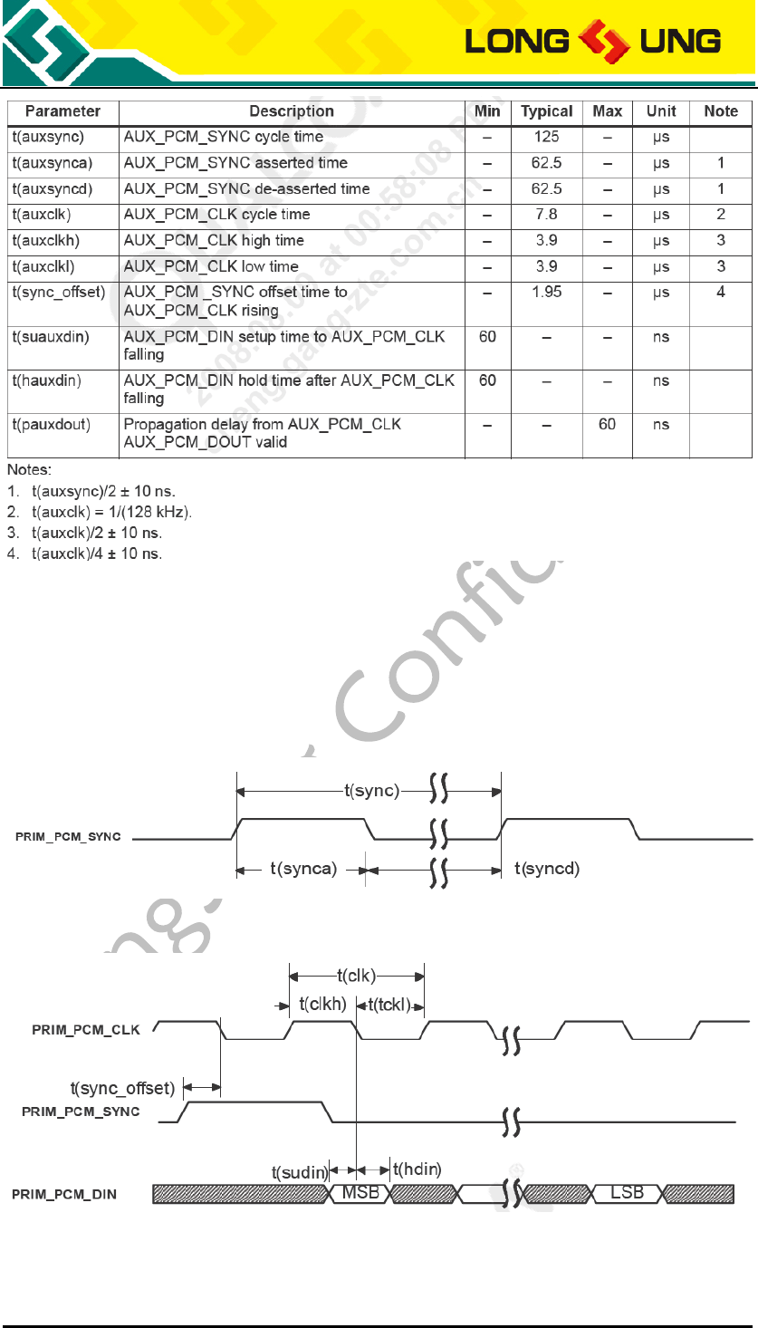
U3500_Hardware_User_Guide _V2.0 Page 54 of 82
3.6.3. Primary PCM
U3500 module firmware default configuration is Primary PCM. PRIM_PCM_CLK
is 2.048 MHz clock, PRIM_PCM_SYNC is 8 kHz (488nS), and μ-law PCM format.
Figure22:PRIM_PCM_SYNC timing
Figure23:PRIM_PCM_CODEC to U3500 timing
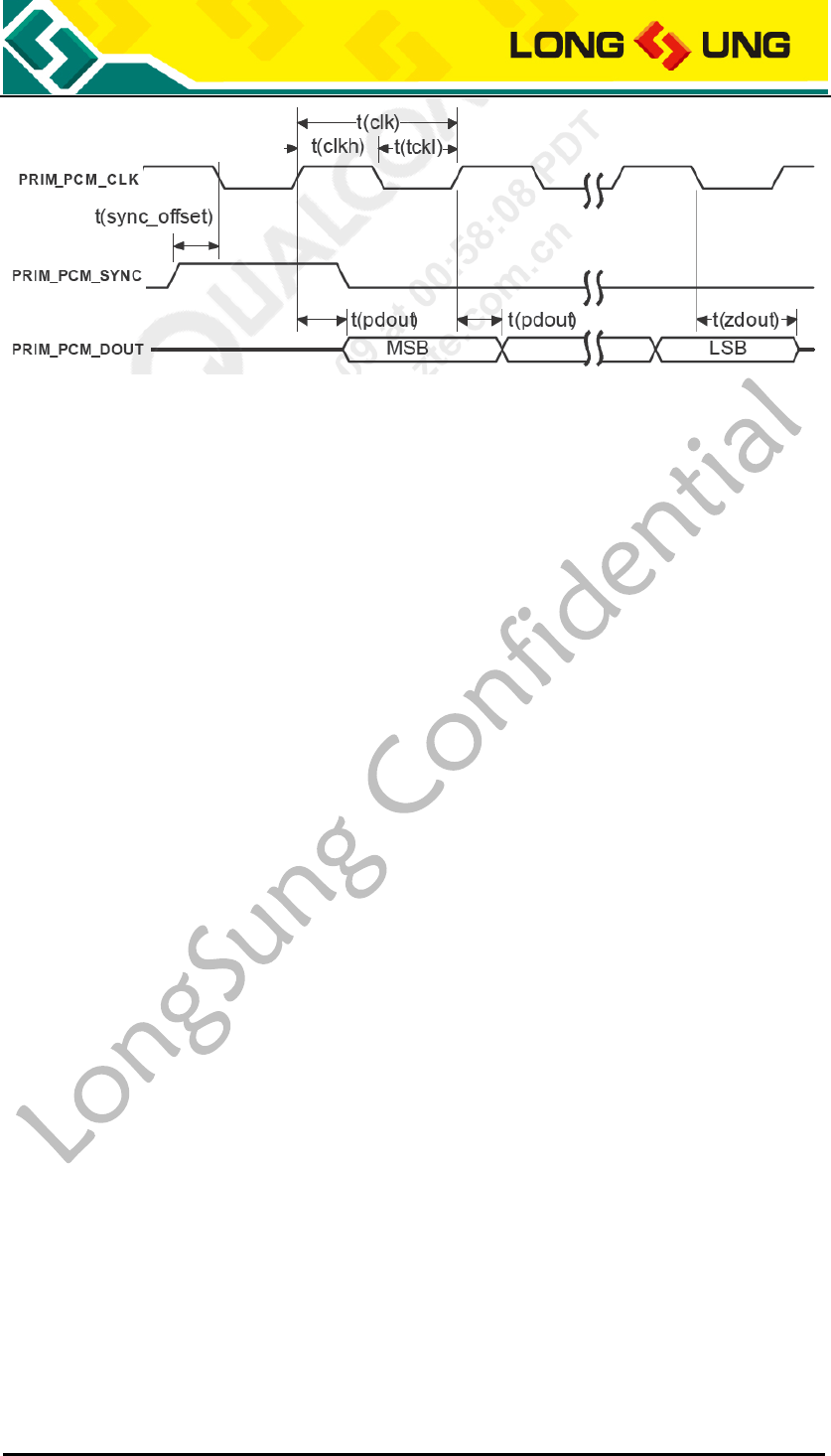
U3500_Hardware_User_Guide _V2.0 Page 55 of 82
Figure24:U3500 to PRIM_PCM_CODEC timing
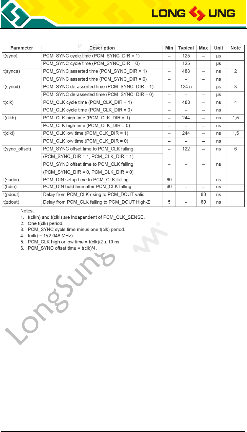
U3500_Hardware_User_Guide _V2.0 Page 56 of 82
Table17:PRIM_CODEC timing parameters
3.6.4. Audio parameters control
U3500 module provides 3 audio interfaces: analog audio, PCM audio, USB audio.
The application terminal can select one of them to use.
Use AT command can switch the audio channel.
The AT command for switch USB or module audio channel:
AT+AUDIOPATH=<value>
<value>:
0: the audio path is model path
1: the audio path is pc path
At the precondition of AT+AUDIOPATH=0, you can select analog or PCM audio:
AT+PCMAUDIO=<value>
<value>:
0:default inner channel (Select analog audio channel)
U3500_Hardware_User_Guide _V2.0 Page 57 of 82
1:change the channel to PCM 16 bit linear
2:change the channel to PCM 8 bit μ-law
3:change the channel to PCM 8 bit A-law
U3500 module audio parameters can be adjusted by AT commands.
Table18:The AT commands for control audio parameters
AT
Command description
AT+CLVL
Set Loudspeaker level
AT+CMUT
Disable/enable mute user voice
AT+CMIC
Set MIC PLUS
AT+ RXVOL
Setting RX volume
AT+SIDET
Change the Side Tone Gain Level
AT+ECHO
Config ESEC and Speaker device echo restrain parameter
AT+ECHO1
Config HEADSET and BTHEADSET device echo restrain parameter
AT+ECHOOFF
Control Echo function open or close
Please get reference from the document《U3500_ATC》
3.7. USIM/SIM interface
U3500 module supports UTMS mode USIM card and GSM/GPRS/EDGE mode
SIM card.
3.7.1. USIM/SIM interface description
U3500 module supports 1.8/3.0V USIM/SIM card.
Table19:U3500 USIM/SIM interface
PIN Name
I/O
PIN Num.
Description
USIM_DATA
I/O
J140
USIM/SIM DATA
USIM_CLK
O
J138
Clock Signal
USIM_RESET
O
J139
RESET Signal
USIM_VCC
O
J141
USIM/SIM Power
USIM_DET
I
J109
USIM/SIM detect
GND
J101, J103~105, J110, J119,
J124~125, J137, J145, J150,
J162, J164, J169, J180~183,
J201~218, J230, J236~237, J242,
J259, J262~274, J301~352
GND

U3500_Hardware_User_Guide _V2.0 Page 58 of 82
3.7.2. USIM/SIM interface reference circuit
For 6-pin USIM/SIM card, we recommend to use the Amphenol C707 10M006
512 2 SIM Holder. For more information, you can visit the Amphenlo company
web: http://www.amphenol.com/
The SPEC of C707 10M006 512 2 SIM Holder is as the figure below.
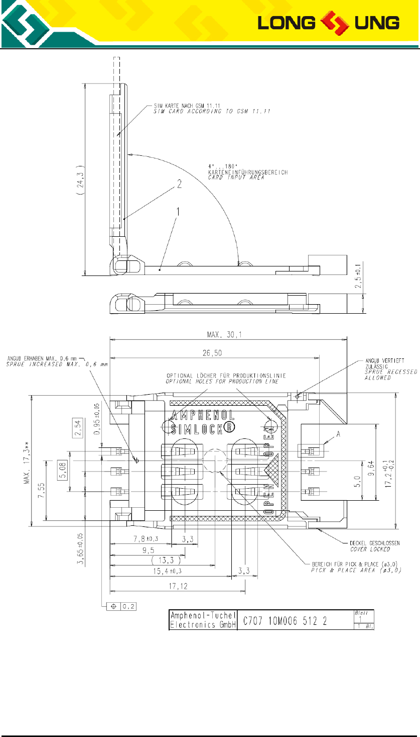
U3500_Hardware_User_Guide _V2.0 Page 59 of 82
Figure25:C707 10M006 512 2 SIM Holder SPEC
USIM/SIM interface reference design circuit as the the figure below.
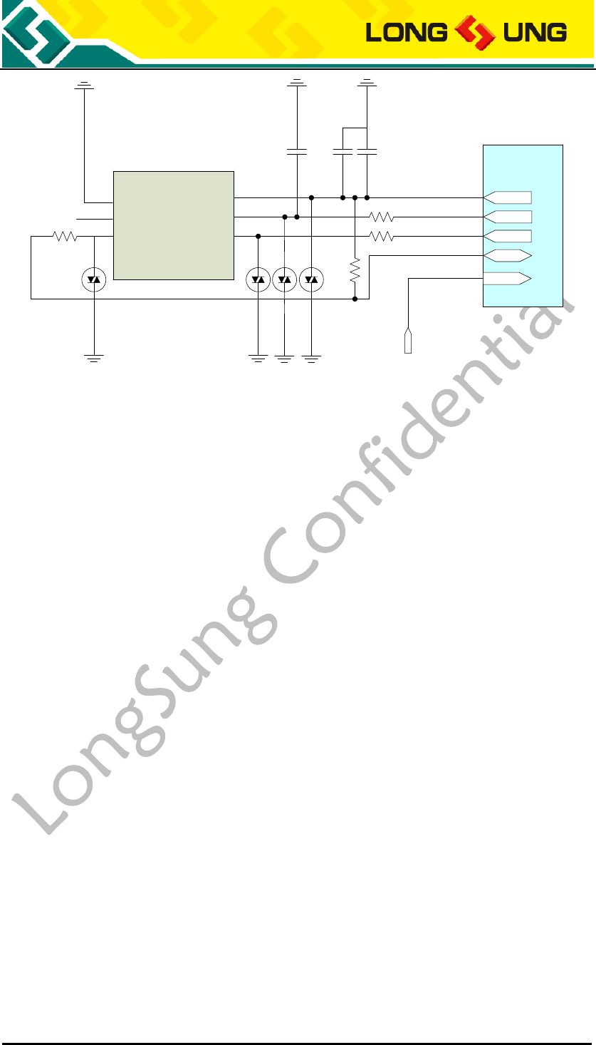
U3500_Hardware_User_Guide _V2.0 Page 60 of 82
U3500
22
22
USIM_VCC
USIM_RESET
USIM_CLK
USIM_DATA
33pF
100nF
VCC
RST
CLK
GND
VPP
IO
1
2
3
6
5
4
22
15K
33pF
ESD
ESD
ESD
ESD
USIM_DET
USIM_DETECT
Figure26:U3500 USIM/SIM interface reference circuit
1) The USIM_DATA line of USIM is connected to USIM_VCC by a pull-up
resistor with reference value 10KΩ.
2) To avoid the instantaneous voltage overflowing, the resistor with reference
value 22Ω can be used for the USIM_DATA, USIM_CLK and USIM_RESET
line.
3) To avoid the static electricity in USIM socket, it is recommended to use the
ESD protection device for the USIM_DATA, USIM_CLK and USIM_VCC line.
4) To get more flat USIM power supply, it is recommended to use the filter
capacitors, and reference value 33pF and 100nF.
5) To eliminate the peak interference and high frequency interference signal on
USIM_RESET line, the filter capacities can be placed in USIM_RESET line,
the reference value is 33pF.
Note: The U3500 can not support USIM/SIM card hot-plugging. If you
hot-plug the USIM/SIM card, may cause the card or U3500 USIM/SIM
interface damage. Please avoid it.
3.8. NETLIGHT output
U3500 module provides 1 NETLIGHT output interface through PINJ115.
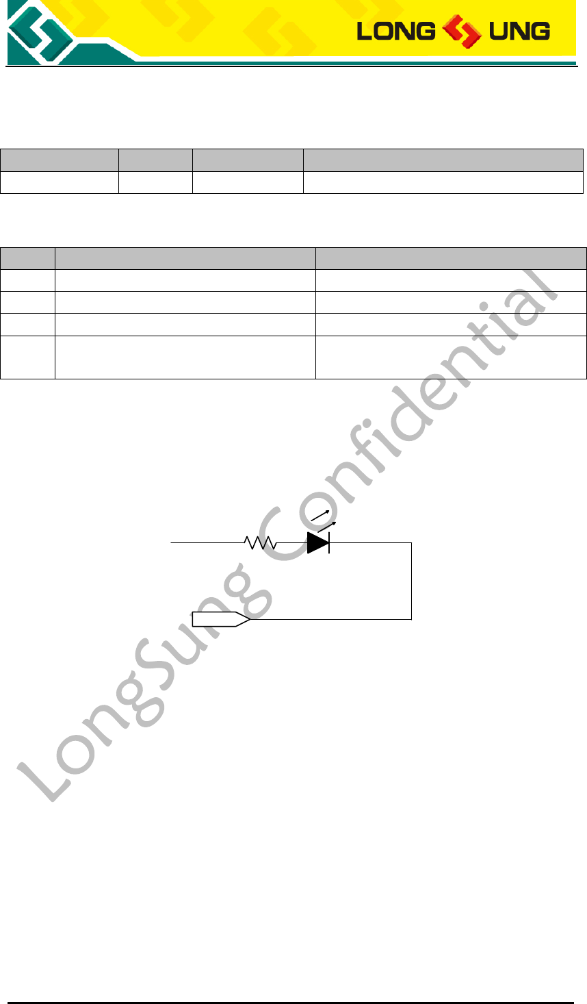
U3500_Hardware_User_Guide _V2.0 Page 61 of 82
3.8.1. NETLIGHT signal description
Table20:U3500 NETLIGHT signal description
PIN Name
I/O
PIN Num.
Description
NETLIGHT
O
J115
Default Netlight
Table21:U3500 net light description
模式
LED Status
Description
1
快闪 (100ms On/800ms Off)
Networks searching
2
慢闪(100ms On/3000ms Off)
Registered in networks
3
速闪(100ms On/300ms Off)
Data connection in networks
4
关闭
Flying mode or Power off or Error(No SIM
card or failed in registering networks )
3.8.2. NETLIGHT reference circuit
The NETLIGHT reference circuit is shown in the figure below.
NETLIGHT
2K
VBAT
Figure27:U3500 NETLIGHT reference circuit
3.9. ADC interface
U3500 module provides two 8Bits ADC interface, which can be used for battery
voltage detect, temperature detector or hardware version detector.
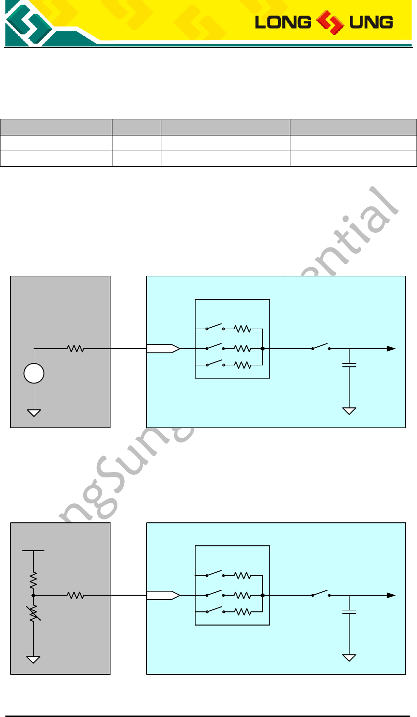
U3500_Hardware_User_Guide _V2.0 Page 62 of 82
3.9.1. ADC interface description
Table22:U3500 ADC interface description
PIN Name
I/O
PIN Num.
Desription
ADC0
I
J120
2.6V
ADC1
I
J261
2.6V
3.9.2. ADC input reference circuit
ADC can be used for battery voltage detector, temperature detector or hardware
version detector. The max input to ADC is 2.6V.
Battery
Temperature
HW_Version
U3500
Input MUX
S2
Cs
VADC
S1 Rin
Rs 10K
ACQ
V
+
_
ADC0/1
Figure28:U3500 ADC input reference circuit
3.9.3. Temperature detector circuit
Temperature U3500
Input MUX
S2
Cs
VADC
S1 Rin
Rs 10K
ACQ
ADC0/1
VREF=2.6V
R1 47K R2
Figure29:U3500 temperature detector circuit
U3500_Hardware_User_Guide _V2.0 Page 63 of 82
R1 is a precision resistor; R2 is a heat-sensitive resistor. VREF is recommended
to 2.6V.
If the HKADC is used for battery voltage detector, because the battery
voltage exceed 2.6V, so must use two precision resistors to create a voltage
divider circuit, make sure the input to ADC is below 2.6V.
If the ADC is used for hardware version detector, use several resistors to get
different voltage input to ADC.
3.10. GPIO interface
U3500 module provides several GPIO; some of them are defined as special
function interface.
Table23:U3500 GPIO interface description
PIN Name
I/O
PIN NO.
Description
PCM_DOUT
O
J112
Default PCM_DOUT
PCM_CLK
I
J114
Default PCM_CLK
PCM_DIN
I
J113
Default PCM_DIN
PCM_SYNC
O
J111
Default PCM_SYNC
AP_IRQ
I
J107
Default AP_RDY
AP_RDY
I
J106
Default AP_RDY
BP_IRQ
O
J108
Default BP_IRQ
UART_TX
O
J173
Default UART_TX
UART_RX
I
J174
Default UART_RX
UART_CTS
I
J175
Default UART_CTS
UART_RTS
O
K176
Default UART_RTS
GPIO1
I/O
J179
Can be used as UART_RI
GPIO2
I/O
J178
Can be used as UART_DCD
GPIO3
I/O
J177
Can be used as UART_DTR
NETLIGHT
O
J115
Default NETLIGHT
3.11. Antenna interface
U3500 provide a stamp hole antenna interface through PINJ102.
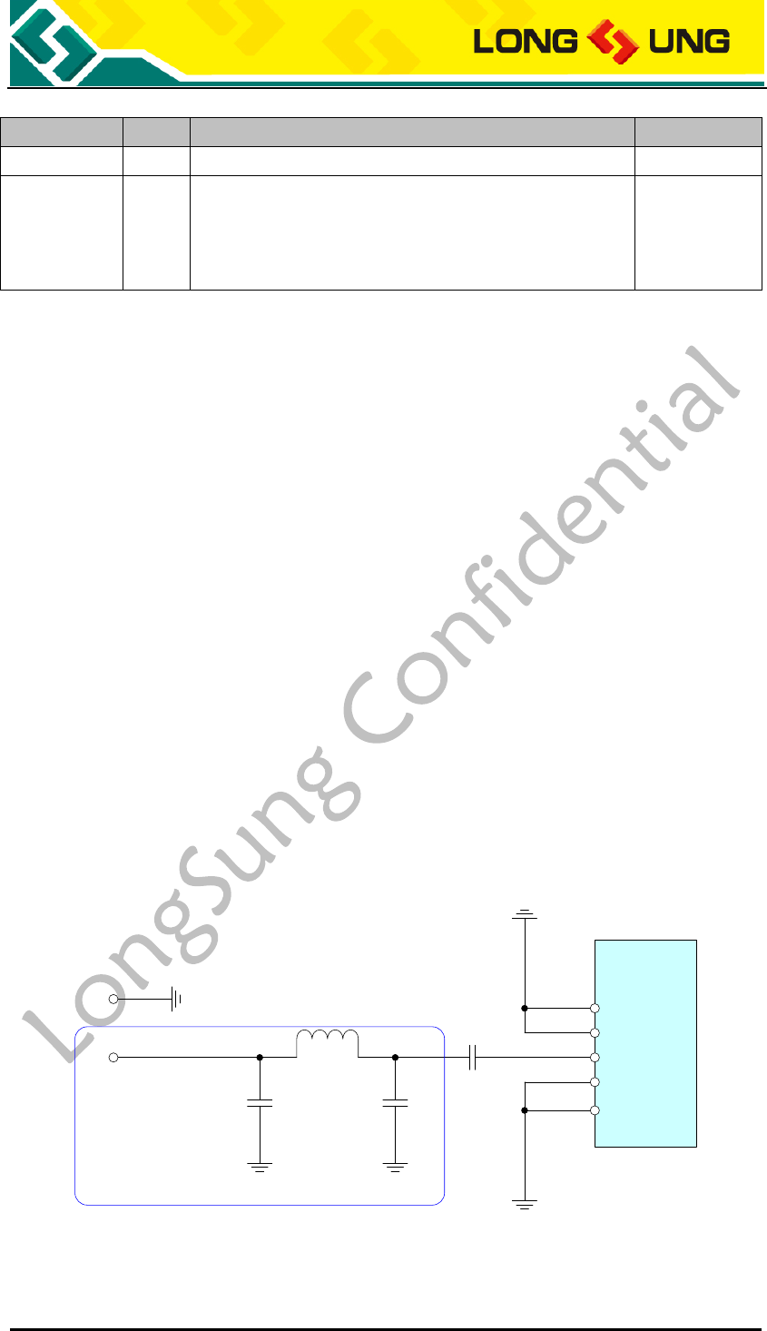
U3500_Hardware_User_Guide _V2.0 Page 64 of 82
Table24:U3500 antenna interface
PIN Name
I/O
PIN Num.
Description
ANT
J102
Antenna
GND
J101, J103~105, J110, J119, J124~125, J137,
J145, J150, J162, J164, J169, J180~183,
J201~218, J230, J236~237, J242, J259,
J262~274, J301~352
GND
U3500 module provides two types antenna interfaces: RF Connector and
antenna pad.
We recommend customer use RF Connector, and use RF cable to plug an
antenna with 50Ω ground impedance.
In the bottom side customer can solder an antenna with 50Ω ground
impedance.
When you use RF Connector, please select the RF cable carefully; it is required
to use RF cable of which the insertion loss should comply with:
GSM900/GSM850<1dB
DCS1800/PCS1900<1.5dB
WCDMA2100<1.5dB
WCDMA850<1dB
3.11.1. Solder antenna
The reference circuit of U3500 solder antenna is shown in below:
U3500
GND
GND
ANT
GND
27pF
GND
L1
C2
NA
C1
0R
C3
NA
2.0×2.0mm
3.0×3.0mm
TP1
TP2
Close to TP1
Figure30:U3500 solder antenna reference circuit
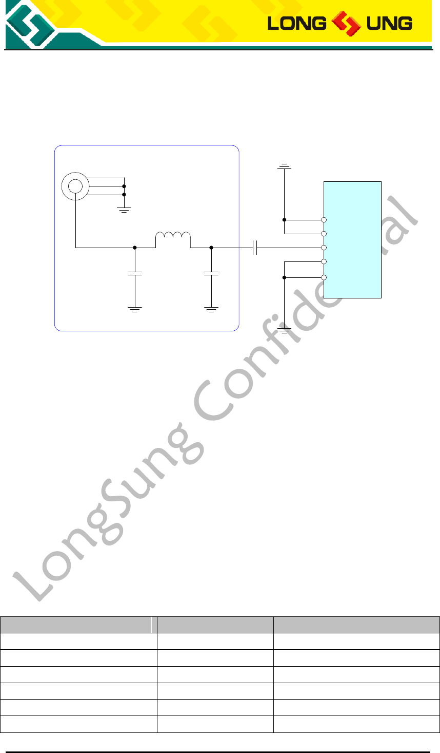
U3500_Hardware_User_Guide _V2.0 Page 65 of 82
3.11.2. RF connector antenna
Portion of the antenna diagram about the antenna using the connector as
below:
U3500
GND
GND
ANT
GND
27pF
GND
L1
C2
NA
C1
0R
C3
NA
Close to J1
J1 MM9329-2700RA1
Figure31: The reference design of RF connector and antenna
3.11.2.1. RF cable
When you use RF Connector, please select the RF cable carefully; it is required
to use RF cable of which the insertion loss should comply with:
GSM900/GSM850<1dB
DCS1800/PCS1900<1.5dB
WCDMA2100<1.5dB
WCDMA850<1dB
3.11.3. U3500 RF output power
Table25:U3500 RF output power
Band
Max
Min
GSM850
33dBm ± 2dB
5dBm ± 5dB
E-GSM900
33dBm ± 2dB
5dBm ± 5dB
DCS1800
30dBm ± 2dB
0dBm ± 5dB
PCS1900
30dBm ± 2dB
0dBm ± 5dB
GSM850(8-PSK)
27dBm ± 3dB
5dBm ± 5dB
E-GSM900(8-PSK)
27dBm ± 3dB
5dBm ± 5dB
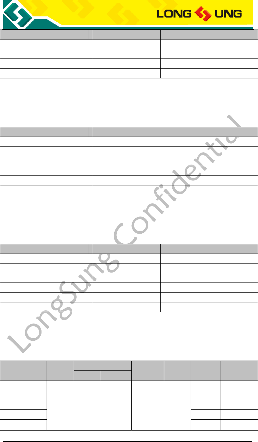
U3500_Hardware_User_Guide _V2.0 Page 66 of 82
Band
Max
Min
DCS1800(8-PSK)
26dBm +3/-4dB
0dBm ± 5dB
PCS1900(8-PSK)
26dBm +3/-4dB
0dBm ± 5dB
WCDMA2100
24dBm +1/-3dB
-56dBm ± 9dB
WCDMA850
24dBm +1/-3dB
-56dBm ± 9dB
3.11.4. U3500 RF receiver sensitivity
Table26:U3500 RF receiver sensitivity
Band
Receive sensitivity
GSM850
<-106dBm
E-GSM900
<-106dBm
DCS1800
<-106dBm
PCS1900
<-106dBm
WCDMA2100
<-108dBm
WCDMA850
<-106dBm
3.11.5. U3500 operating frequencies
Table27:U3500 operating frequencies
Band
Receive
Transmit
GSM850
869~894MHz
824~849MHz
E-GSM900
925~960MHz
880~915MHz
DCS1800
1805~1880MHz
1710~1785MHz
PCS1900
1930~1990MHz
1850~1910MHz
WCDMA2100
2110~2170MHz
1920~1980MHz
WCDMA850
869~894MHz
824~849MHz
3.11.6. Antenna parameters requirement
Table28:U3500 antenna parameters requirement
Band
VSWR
Gain
Efficiency
SAR
TRP
(dBm)
TIS
(dBm)
Peak
Avg.
GSM850
<2.5:1
>0dBi
>-4dBi
>40%
<1.6
W/Kg
29
<-102
EGSM900
29
<-102
DCS1800
26
<-102
PCS1900
26
<-102
WCDMA850
19
<-102
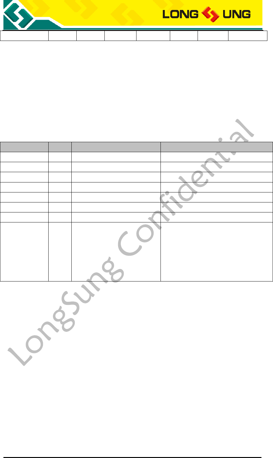
U3500_Hardware_User_Guide _V2.0 Page 67 of 82
WCDMA2100
19
<-104
3.12. Micro SD card interface
U3500 provide a Micro SD card interface for extending the system storage, this
interface can be designed as a T-Flash card and MMC card too.
3.12.1. Micro SD card interface description
Table29:U3500 Micro SD card interface
PIN Name
I/O
PIN Num.
Description
VREG_MMC
O
J130
2.6V, the power supply for SD card
SDCC1_DATA0
I/O
J131
SD Interface, can be used as GPIO
SDCC1_DATA1
I/O
J132
SD Interface, can be used as GPIO
SDCC1_DATA2
I/O
J133
SD Interface, can be used as GPIO
SDCC1_DATA3
I/O
J134
SD Interface, can be used as GPIO
SDCC1_CLK
O
J135
SD Interface, can be used as GPIO
SDCC1_CMD
O
J136
SD Interface, can be used as GPIO
GND
J101, J103~105, J110, J119,
J124~125, J137, J145, J150,
J162, J164, J169, J180~183,
J201~218, J230, J236~237,
J242, J259, J262~274,
J301~352
GND
3.12.2. Micro SD interface reference circuit
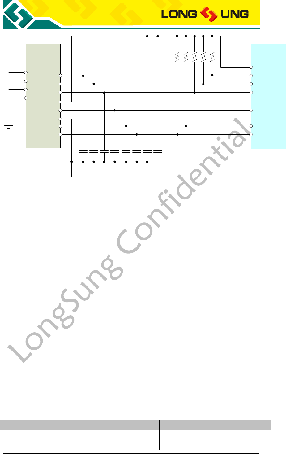
U3500_Hardware_User_Guide _V2.0 Page 68 of 82
U3500
VREG_MMC
33pF
8
10K
SDCC1_DATA2
SDCC1_DATA3
SDCC1_CMD
SDCC1_CLK
SDCC1_DATA0
J3
1
2
3
5
4
6
7
11
10
9
12
SDCC1_DATA1
10K
10K
10K
10K
33pF
33pF
33pF
33pF
33pF
33pF
100nF
LS_PS_MC_001
Figure32:U3500 Micro SD card interface reference circuit
1) Data line SDCC1_DATA0, SDCC1_DATA1, SDCC1_DATA2, SDCC1_DATA3
and SDCC1_CMD should be pulled-up to VREG_MMC by a 10Kohm resistor;
2) For stabling the VREG_MMC, where should connect two filter capicator to
GND with value 33pF and 100nF;
3) For eliminating the high frequence disturb, where should connect a filter
capicator to GND with value 33pF;
4) For improving the ESD performance, where should connect ESD protect
device close the MicroSD connector.
3.13. Camera interface
U3500 provide a camera interface, which include:
10 bits bus data, which are used for video data input;
Horizotal and vertical synchronous signals;
Two IIC bus, which are used for controlling the U3500 and the camera.
3.13.1. Camera interface description
Table30:U3500 Camera interface
PIN Name
I/O
PIN Num.
Description
CAMIF_DATA0
O
J151
Bit 0 of RGB or YUV D0 video output
CAMIF_DATA1
O
J152
Bit 1 of RGB or YUV D1 video output
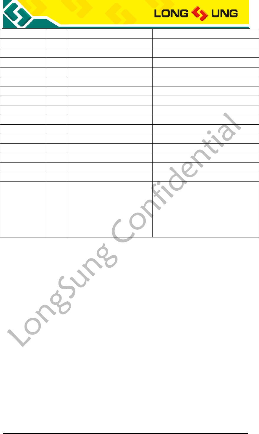
U3500_Hardware_User_Guide _V2.0 Page 69 of 82
CAMIF_DATA2
O
J153
Bit 2 of RGB or YUV D2 video output
CAMIF_DATA3
O
J154
Bit 3 of RGB or YUV D3 video output
CAMIF_DATA4
O
J155
Bit 4 of RGB or YUV D4 video output
CAMIF_DATA5
O
J156
Bit 5 of RGB or YUV D5 video output
CAMIF_DATA6
O
J157
Bit 6 of RGB or YUV D6 video output
CAMIF_DATA7
O
J158
Bit 7 of RGB or YUV D7 video output
CAMIF_DATA8
O
J159
Bit 8 of RGB or YUV D8 video output
CAMIF_DATA9
O
J160
Bit 9 of RGB or YUV D9 video output
CAMIF_PCLK
O
J161
Pixel clock output
CAMIF_MCLK
I
J163
Master clock input
CAMIF_HSYNC
O
J165
Horizontal line synchronization signal
CAMIF_VSYNC
O
J166
Vertical sync output
CAMIF_RESET
O
J167
Master reset input, active low
CAMIF_EN
O
J168
Vidio enable
I2C_SDA
I/O
J116
Serial interface data input and output
I2C_SCL
O
J117
Serial interface clock output
GND
J101, J103~105, J110, J119,
J124~125, J137, J145, J150,
J162, J164, J169, J180~183,
J201~218, J230, J236~237,
J242, J259, J262~274,
J301~352
GND
3.13.2. Camera interface reference circuit
U3500 provide a camera interface, which support the YUV format, the maximum
pixel is 2M, the voltage level is 2.6V.
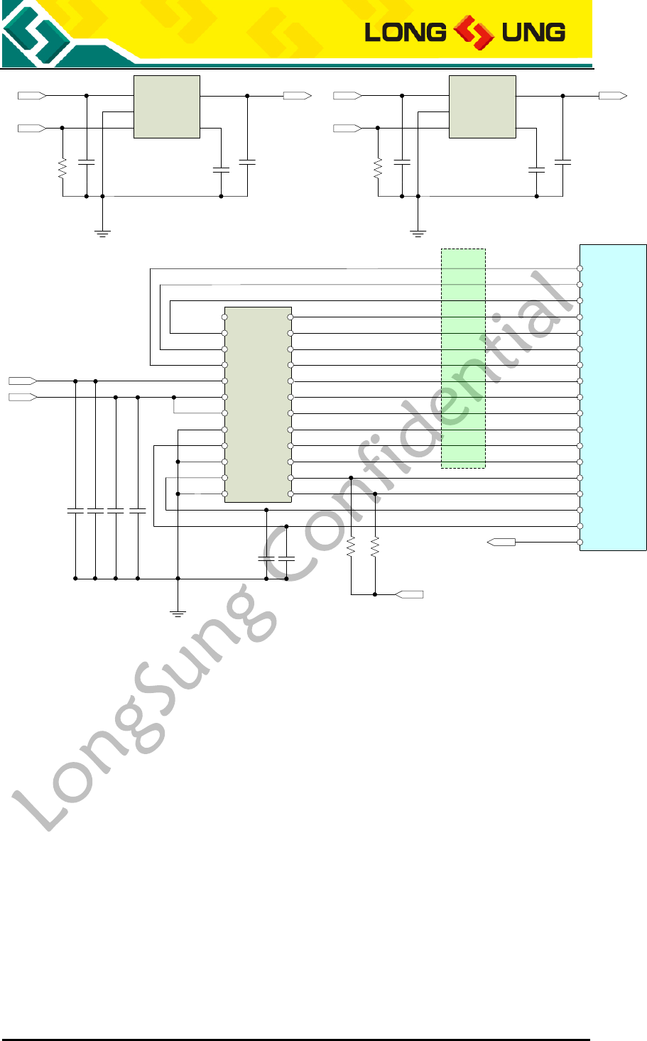
U3500_Hardware_User_Guide _V2.0 Page 70 of 82
47K
24 Y0
2.2uF
100nF
2.2uF
100nF
U3500
J4 23 Y1
22 Y2
21 Y3
20 Y4
19 Y5
18 Y6
17 Y7
16 Y8
15 Y9
14 SIO_C
13 SIO_D
PWDN 1
HREF 2
VSYNC 3
RESET 4
DVDD_1.8V 5
DOVDD_2.8V 6
AVDD 7
AGND 8
PCLK 9
DGND 10
MCLK 11
DGND 12
CAMIF_DATA0
CAMIF_DATA1
CAMIF_DATA2
CAMIF_DATA3
CAMIF_DATA4
CAMIF_DATA5
CAMIF_DATA6
CAMIF_DATA7
CAMIF_DATA8
CAMIF_DATA9
I2C_SCL
I2C_SDA
EMI
CAMIF_HSYNC
CAMIF_VSYNC
CAMIF_RESET
CAM_1V5
CAM_2V8
CAMIF_MCLK
CAMIF_PCLK
CAMIF_EN
47K
VOUT
NC
NC
U1
1 VIN
2.2uF
100K
2 GND
3 EN
VOUT 5
BP 4
VBAT
CAMIF_EN
22nF
2.2uF
CAM_2V8
U2
1 VIN
2.2uF
100K
2 GND
3 EN
VOUT 5
BP 4
VBAT
CAMIF_EN
22nF
2.2uF
CAM_1V5
LS_RT9193_28PU5 LS_RT9193_15PU5
Figure33:U3500 Camera interface reference circuit
3.14. Keypad interface
U3500 provide a 5*5 keypad matrix, for the non-customized customer, these
pins can be floated.
3.15. LCD interface
U3500 provide a LCD interface, which support the format of QVGA, the
maximum pixel is 320*240, the voltage level is 1.8V, for non-customized
customer, these pins can be floated.

U3500_Hardware_User_Guide _V2.0 Page 71 of 82
3.16. 32K_CLK_BT interface
U3500 provide a 32KHz clock for Bluetooth, for non-customized customer, these
pins can be floated.
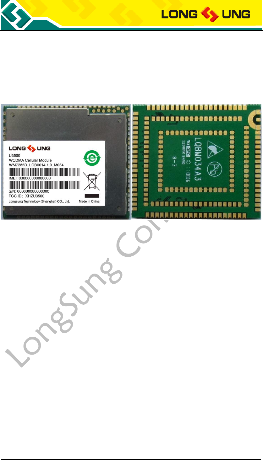
U3500_Hardware_User_Guide _V2.0 Page 72 of 82
4. Mechanics
4.1. The view of U3500
Figure34:The top and bottom view of U3500
4.2. Module 3D stack
If you need the 3D stack of U3500, please contact us to obtain it.
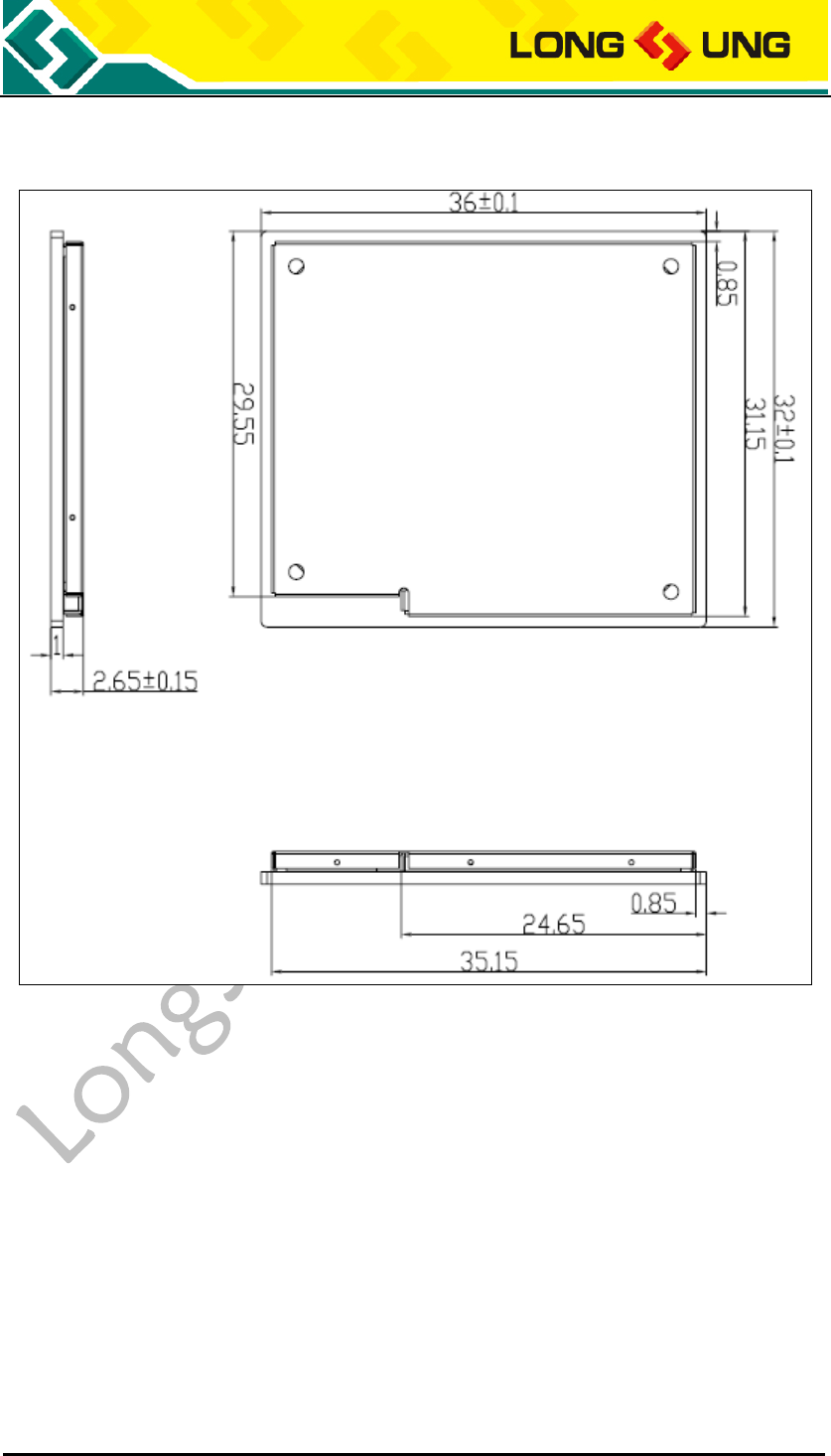
U3500_Hardware_User_Guide _V2.0 Page 73 of 82
4.3. Module 2D mechanical dimensions
Figure35:U3500 2D mechanical dimensions
4.4. Application side decals of U3500
The decals include schematic decal and PCB decal. Please contact us to obtain
them.
4.5. RF connector
U3500 module side uses a RF connector for WCDMA/GSM antenna. The RF
connector is MURATA MM9329-2700RA1. We recommend customer select a RF
cable with a MURATA MXTK88TK2000 RF connector.
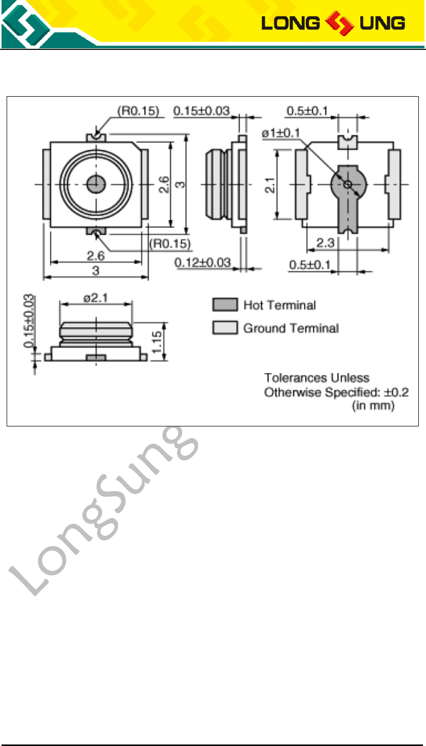
U3500_Hardware_User_Guide _V2.0 Page 74 of 82
4.5.1. Module side RF connector
Figure36:The mechanical dimensions of MM9329-2700RA1
4.5.2. Application side RF connector
We recommend customer use MURATA MXTK88TK2000 in application side.
The mechanical dimensions of MURATA MXTK88TK2000 RF connector is shown
at figure below.
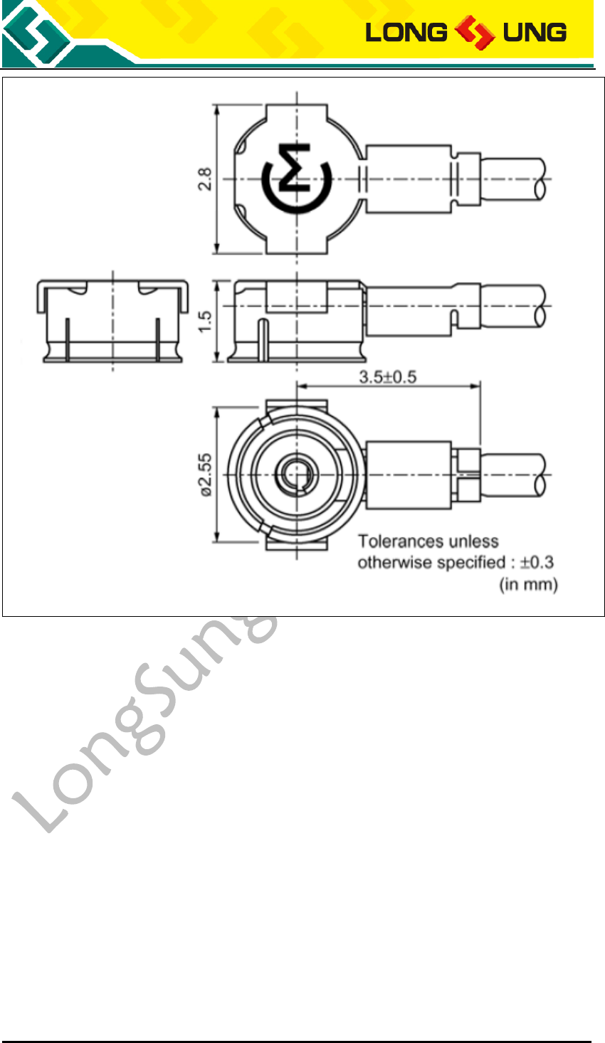
U3500_Hardware_User_Guide _V2.0 Page 75 of 82
Figure37:The mechanical dimensions of MXTK88TK2000
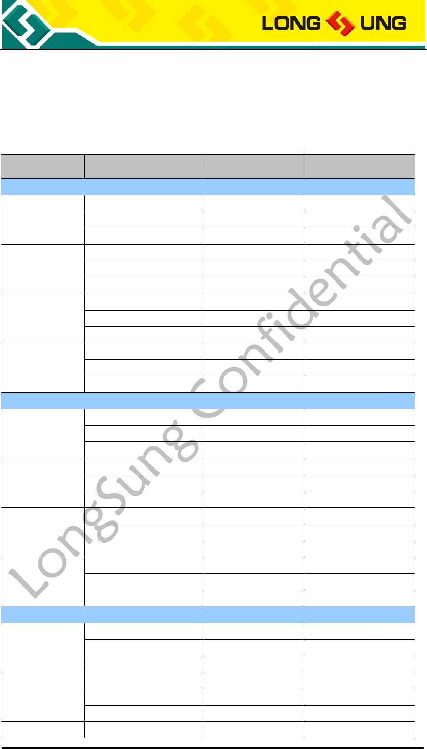
U3500_Hardware_User_Guide _V2.0 Page 76 of 82
5. Power consumption
U3500 current consumption (VBAT Power supply: DC3.8V) is shown in Table28.
Table31:U3500 max current consumption in some mode
Band
Channel
Power(dBm)
Current(mA)
TALK mode(GSM)
GSM850
128
32.1
298
189
32
296
251
31.8
294
GSM900
975
32.5
290
38
32.5
289
124
32.3
268
DCS1800
512
29.4
241
698
29.6
232
885
29.4
219
PCS1900
512
29.5
203
661
29.3
194
810
29.4
192
DATA mode GPRS(1Rx,4Tx)
GSM850
128
25.9
512
189
25.7
495
251
25.5
487
GSM900
975
25.6
495
38
25.6
471
124
25.3
432
DCS1800
512
24.2
434
698
24.2
420
885
24
392
PCS1900
512
24.2
362
661
24
345
810
24.2
343
DATA mode EGPRS(1Rx,4Tx)
GSM850
128
22.6
376
189
22.5
369
251
22.3
365
GSM900
975
22.3
365
38
22.1
352
124
22.1
327
DCS1800
512
22.3
367
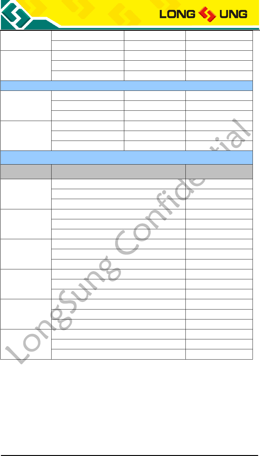
U3500_Hardware_User_Guide _V2.0 Page 77 of 82
698
22.3
356
885
22.1
334
PCS1900
512
22.5
311
661
22.3
297
810
22.4
295
DATA mode (WCDMA)
W2100
10562
22.7
545
10700
22.3
461
10838
22.2
495
W850
4357
22
461
4408
22.1
455
4458
22
488
Sleep mode current consumption
Band
Setting
Current(mA)
GSM850
2
3.2
5
2.1
9
1.5
GSM900
2
3.1
5
1.9
9
1.5
DCS1800
2
3.1
5
1.8
9
1.5
PCS1900
2
2.9
5
2
9
1.4
W2100
6
3.9
7
2.4
9
0.8
W850
6
3.9
7
2.7
9
0.8
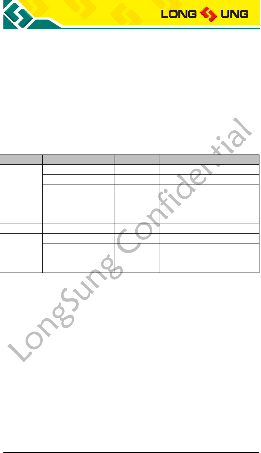
U3500_Hardware_User_Guide _V2.0 Page 78 of 82
6. Electrical characteristics
6.1. Absolute maximum power ratings
Absolute maximum power ratings for power supply and the voltage on digital
and analog pins of U3500 module are listed in the Table29. Out of the range, the
module should be damaged.
Table32:Absolute maximum power ratings
Parameter
Description
Min
Typ
Max
Unit
VBAT
U3500 power supply
-0.3
3.8
4.2
V
RMS average current
0
0.9
A
Voltage drop during
transmit burst, IVBA
peak current may up to
2A (Per 4.6ms)
400
mV
USB_VBUS
USB power supply
5.0
5.25
V
GPIO
Digital IO voltage
-0.3
2.6
3.0
V
Voltage in power off
mode
-0.25
0.25
V
ADC
Analog input
-0.3
2.6
3.0
V
6.2. Operating temperatures
U3500 module can normal operate in the environment temperature in
-20~+65℃.
If you will use it in the environment which out of the range, we recommend
customer has some method to control the temperature around U3500 module.
In the restricted operation temperature, some RF parameter may out of the
3GPP RF standard. The module can work, such as voice, SMS, data.
In the storage temperature, the module may be not able to work, just for
storage. The temperature out of the range, the U3500 module should be
damaged.
Table33:U3500 module operating temperature
U3500_Hardware_User_Guide _V2.0 Page 79 of 82
Temperature
Min
Typ
Max
Unit
Normal operation
temperature
-20
25
65
℃
Restricted operation
temperature
-30 ~ -20
65 ~ 75
℃
Storage
temperature
-40
80
℃
U3500_Hardware_User_Guide _V2.0 Page 80 of 82
6.3. Interface operating status
VL: logistic Low level
VH: logistic High level
Table34:Digital Signal DC Characteristics
Signal
VL
VH
Unit
Min
Max
Min
Max
Input
-0.3
0.35* VDD-PX
0.65* VDD-PX
VDD-PX+0.3
V
Output
GND
0.45
VDD-PX -0.45
VDD-PX
V
Note: VDD-PX=2.5~2.7V
Table35:U3500 power supply range
Parameter
I/O
Min
Typ
Max
Unit
VBAT
I
3.5
3.8
4.2
V
USB_VBUS
I
4.4
5.0
5.25
V
USIM_VCC
O
1.7/2.75
1.8/2.85
1.9/2.95
V
6.4. Reliability
Table36:Requirements on the environment reliability
Test case
Test requirement
Low
temperature
Storage test
-40℃±3 ℃, power off mode storage 24 hours
High
temperature
Storage test
+85℃±3 ℃, power off mode storage 24 hours
Temperature
change test
In power off mode, between -40℃ and +85℃, stay 0.5h, change time
<3min, total 24 times
High
temperature
high humidity
test
Temperature: +85℃±3 ℃
Humidity: 90~95%RH
Power off mode storage 24 hours
Low
temperature
operating
-20℃±3 ℃, keep operating for 24 hours
High
temperature
operating
+65℃±3 ℃, keep operating for 24 hours
U3500_Hardware_User_Guide _V2.0 Page 81 of 82
Test case
Test requirement
Vibration test
Vibration test requirement:
Frequency
Random Vibration ASD
5~20Hz
0.96m2/s3
20~500Hz
0.96m2/s3(20Hz), else -3dB/times frequency
Connector Life
Test
Board-to-board connector plug 50 times; RF connector plug 30 times
ESD test
1, When module in voice mode, discharge antenna port, VBAT PAD and
GND, ESD must meet the following targets:
1) Contact discharge pass: ±2KV、±4KV test class
2) Air discharge pass: ±2KV、±4KV、±8KV test class
2, When module in voice mode, discharge SIM card hold of EVB, ESD must
meet the following targets:
1) Contact discharge pass: ±2KV test class
2) Air discharge pass: ±2KV、±4KV test class
U3500_Hardware_User_Guide _V2.0 Page 82 of 82
6.5. Electrostatic discharge
U3500 module is a consumptive product. Although the module has some ESD
protect function, we recommend in application need more ESD protect means to
avoid the static electricity from the application environment, please reference to
the interface reference design circuit.
In order to improve the antistatic performance of the system, we recommend
customer is advised of the following main board: layout an exposed copper
under the module U3500, U3500 shield frame solder feet welded to the
customer board. The solder feet, copper, solder feet and GND are connected.
The ESD capacity of U3500 is listed in the table below.
Table37:The ESD endure status measured table
(Temperature: 25℃, Humidity: 45%)
Part
Air discharge
Contact discharge
VBAT,GND
±8KV
±4KV
Antenna port
±8KV
±4KV
Other port
±4KV
±2KV