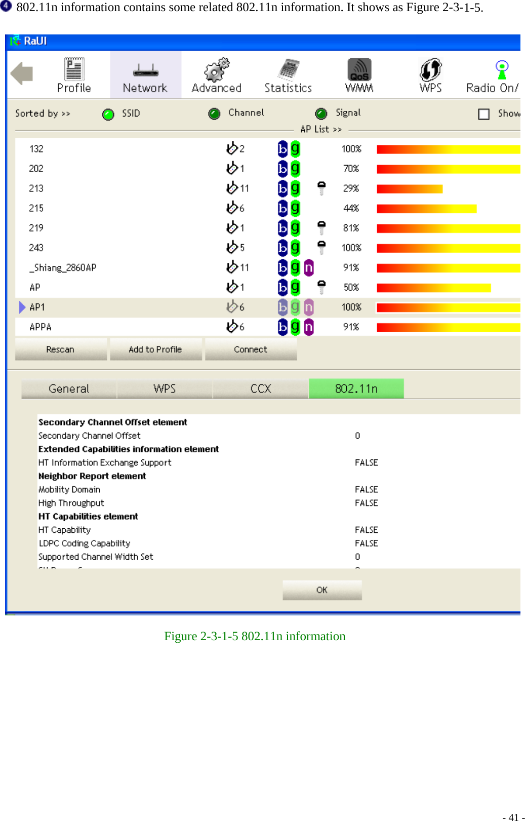
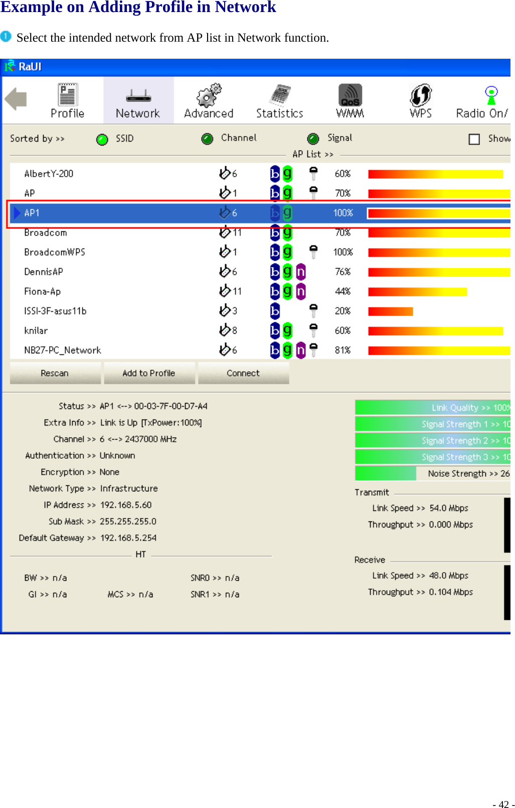
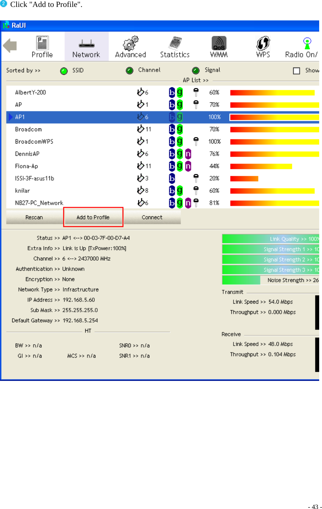
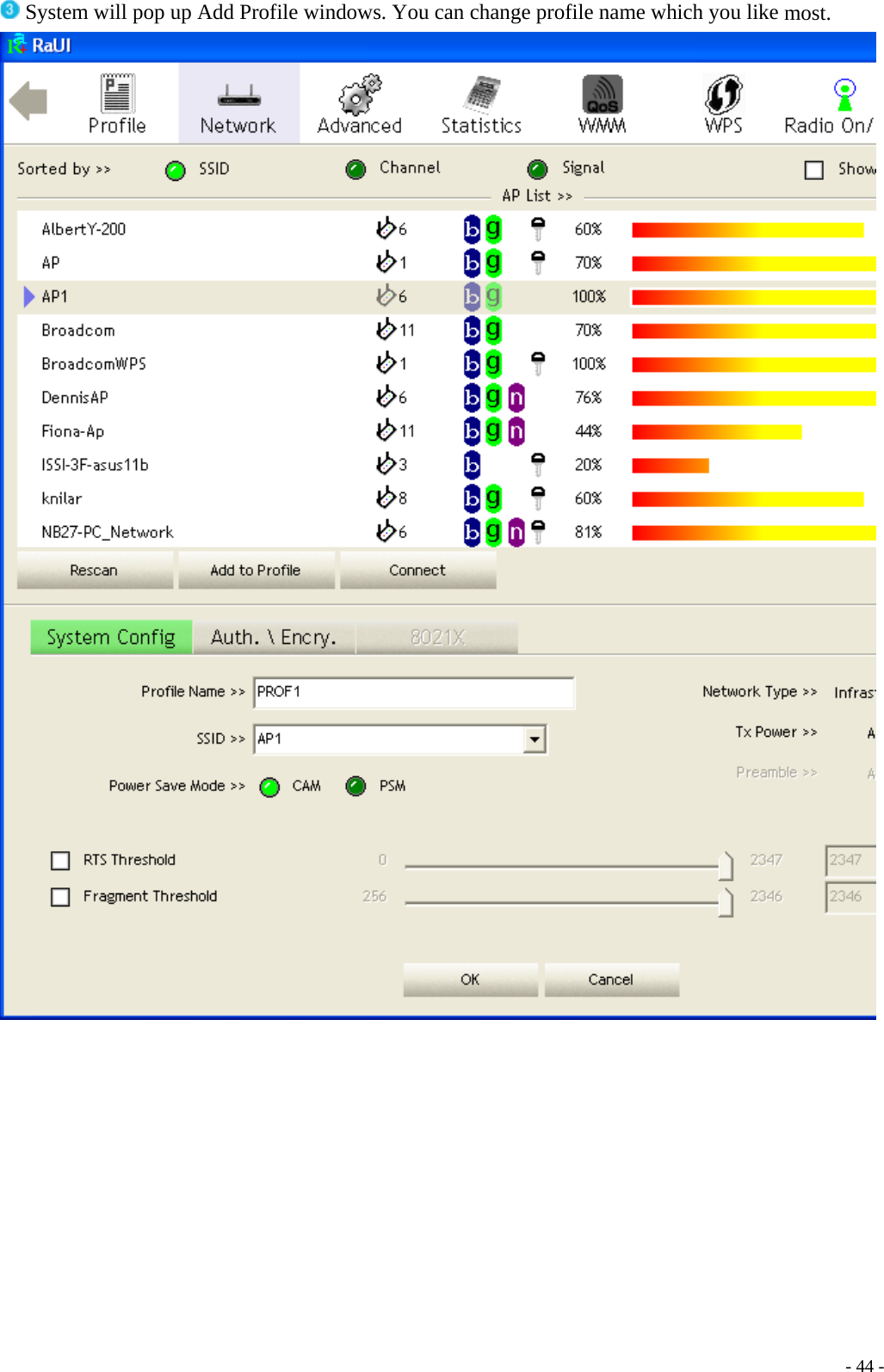
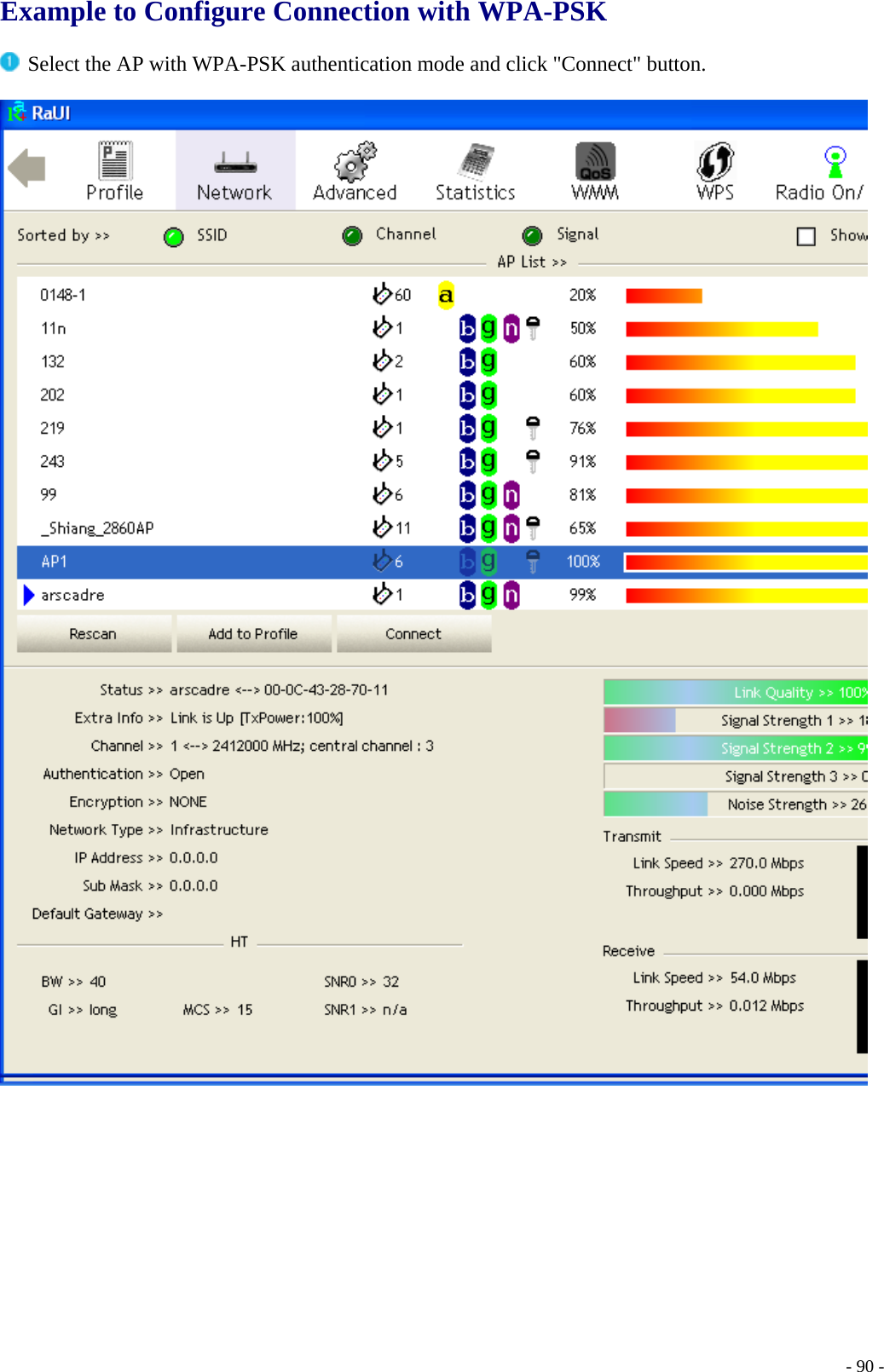
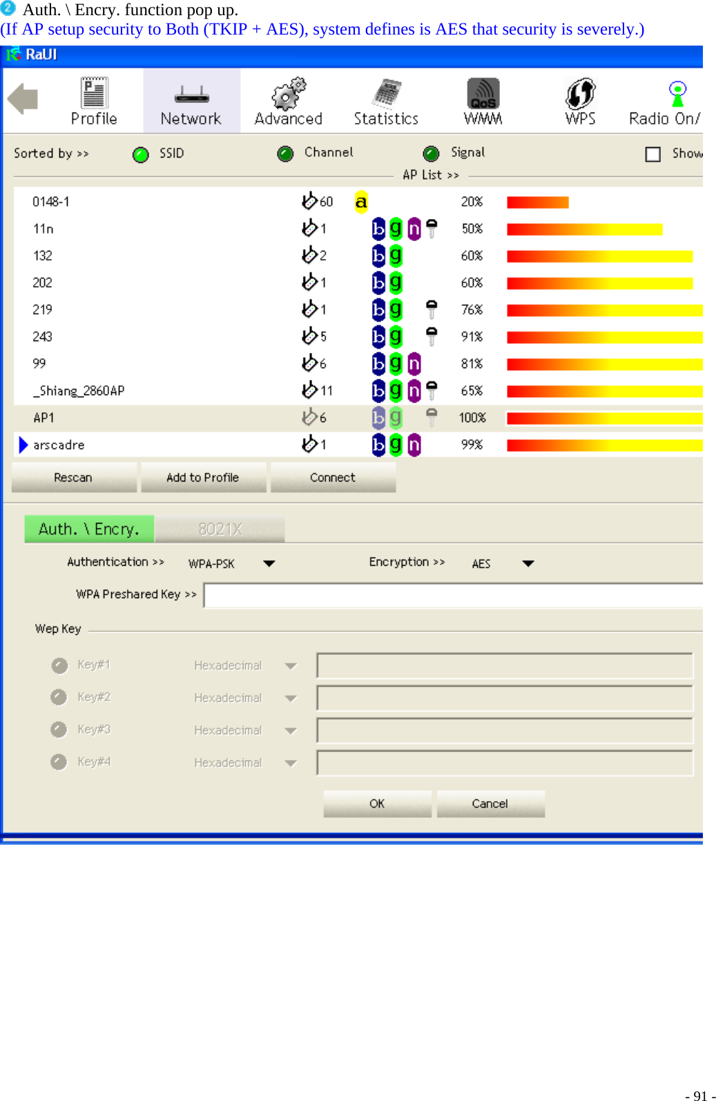
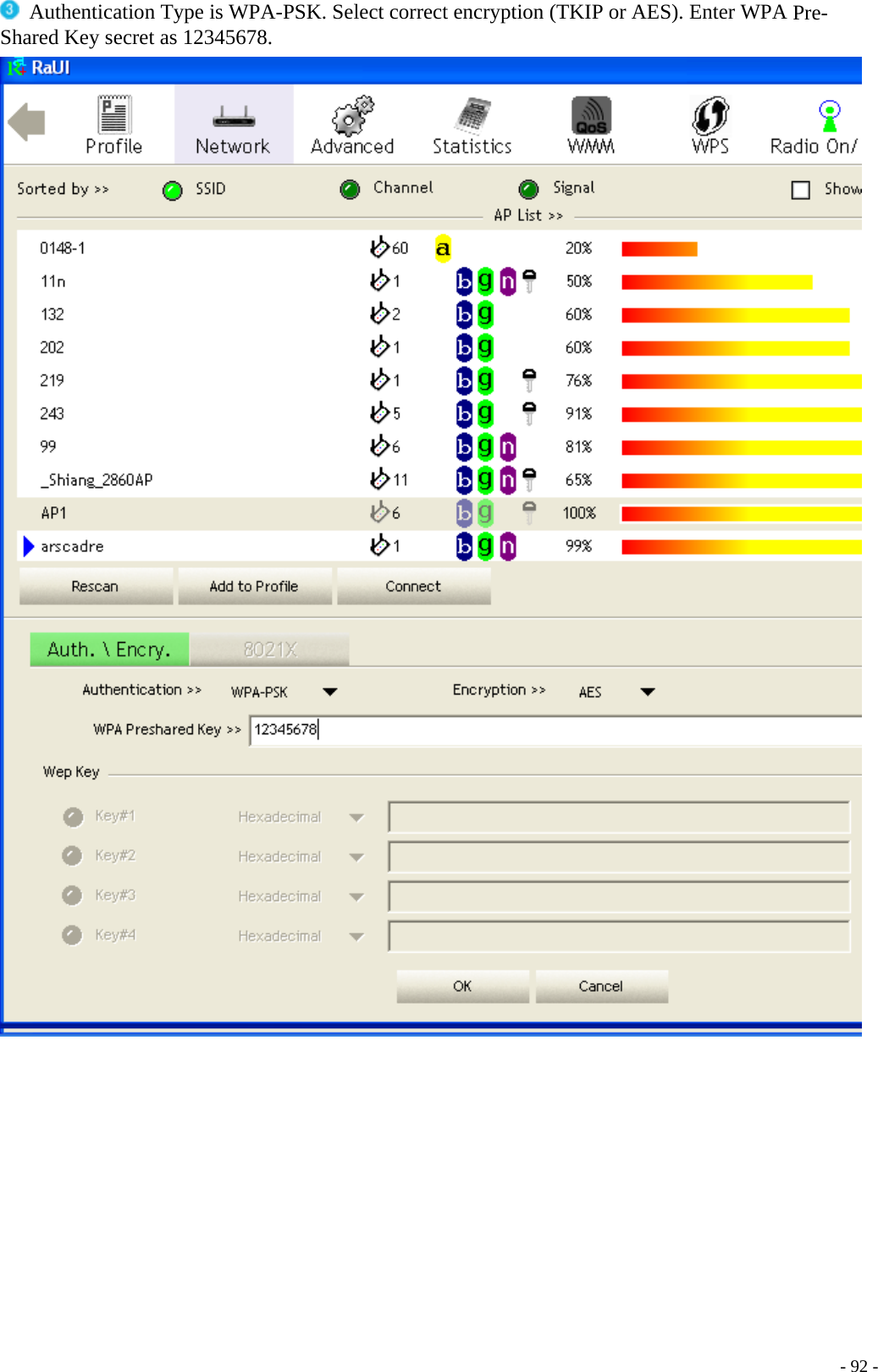
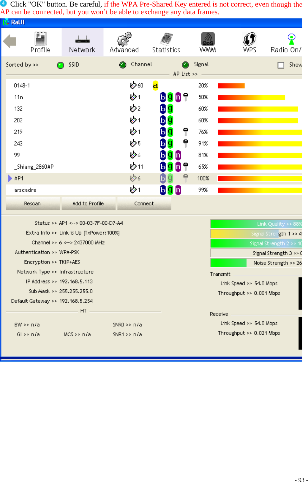
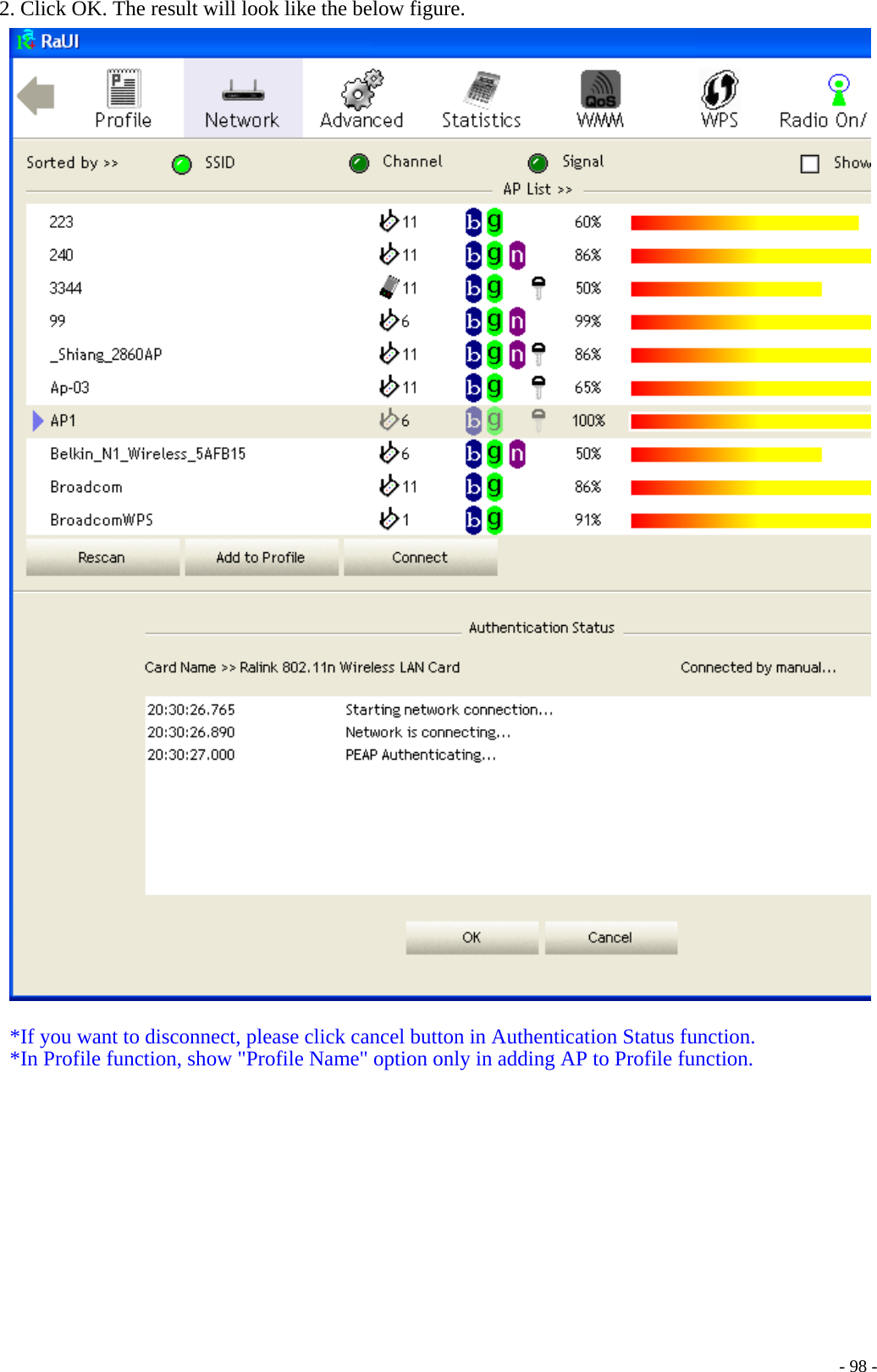
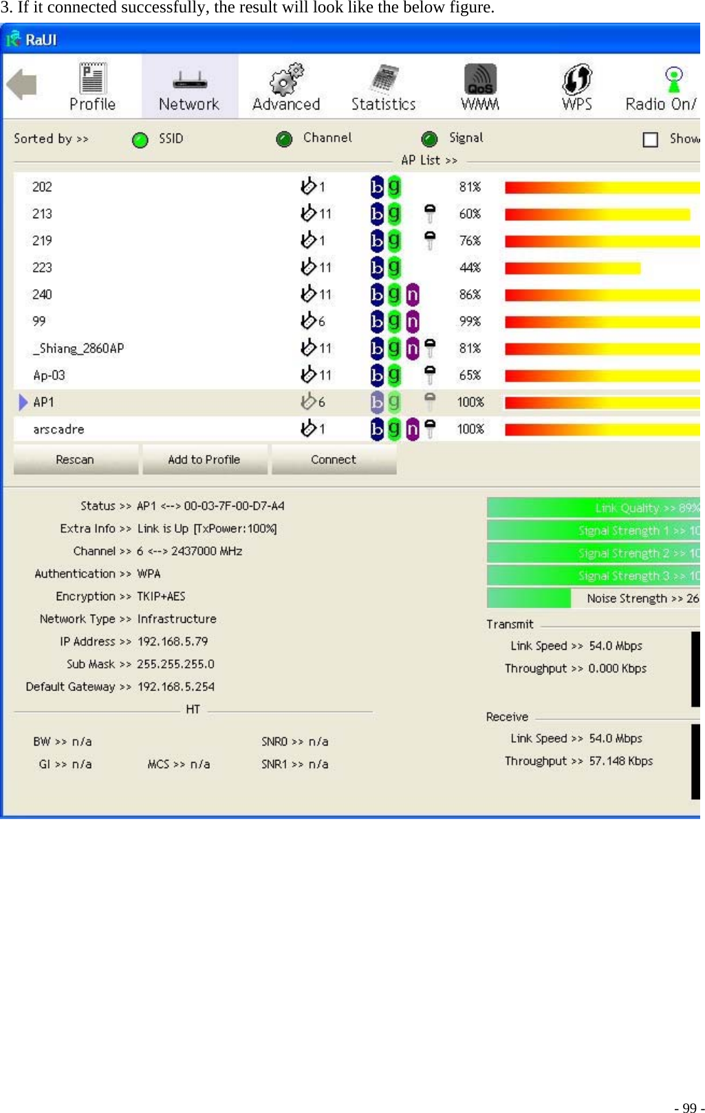
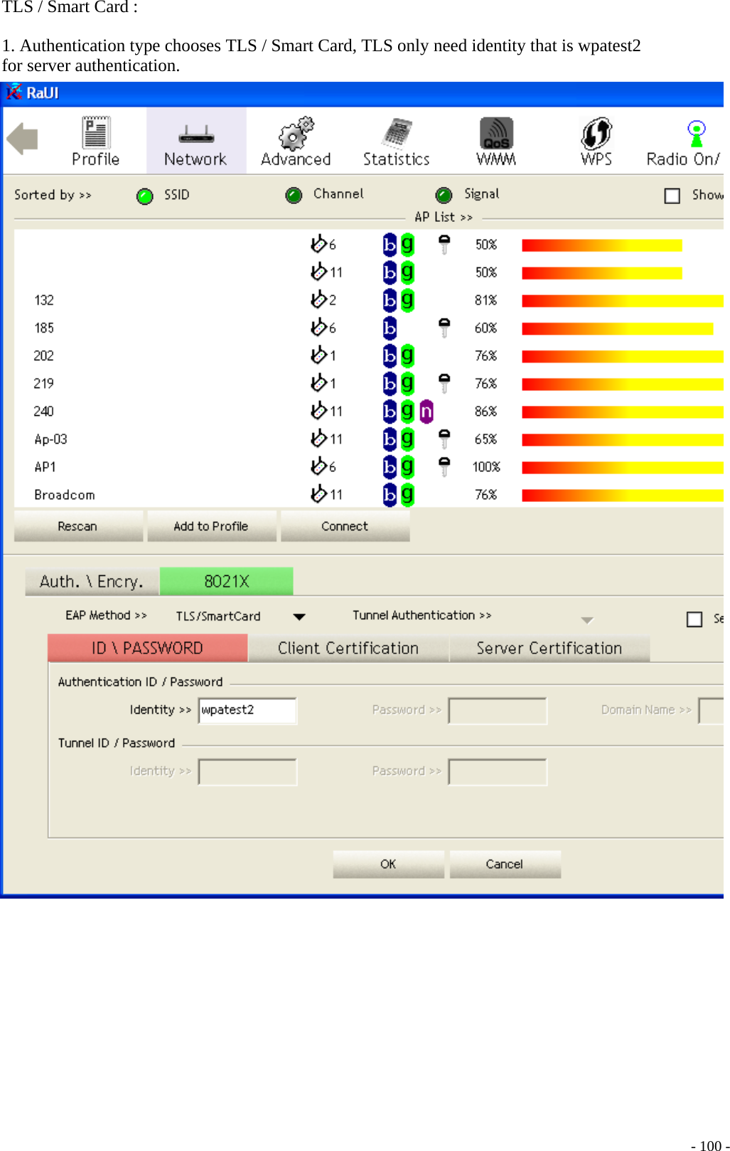
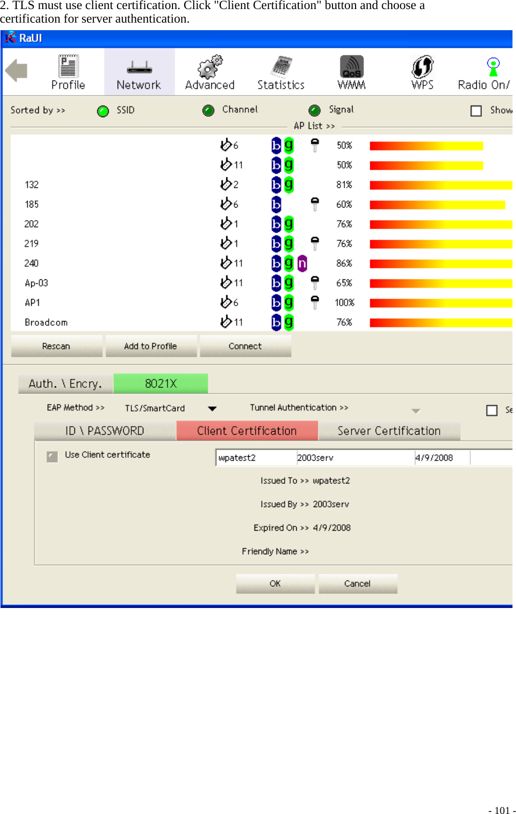
Loopcomm Technology LP-7185 802.11b/g WLAN PCI Adapter User Manual Title

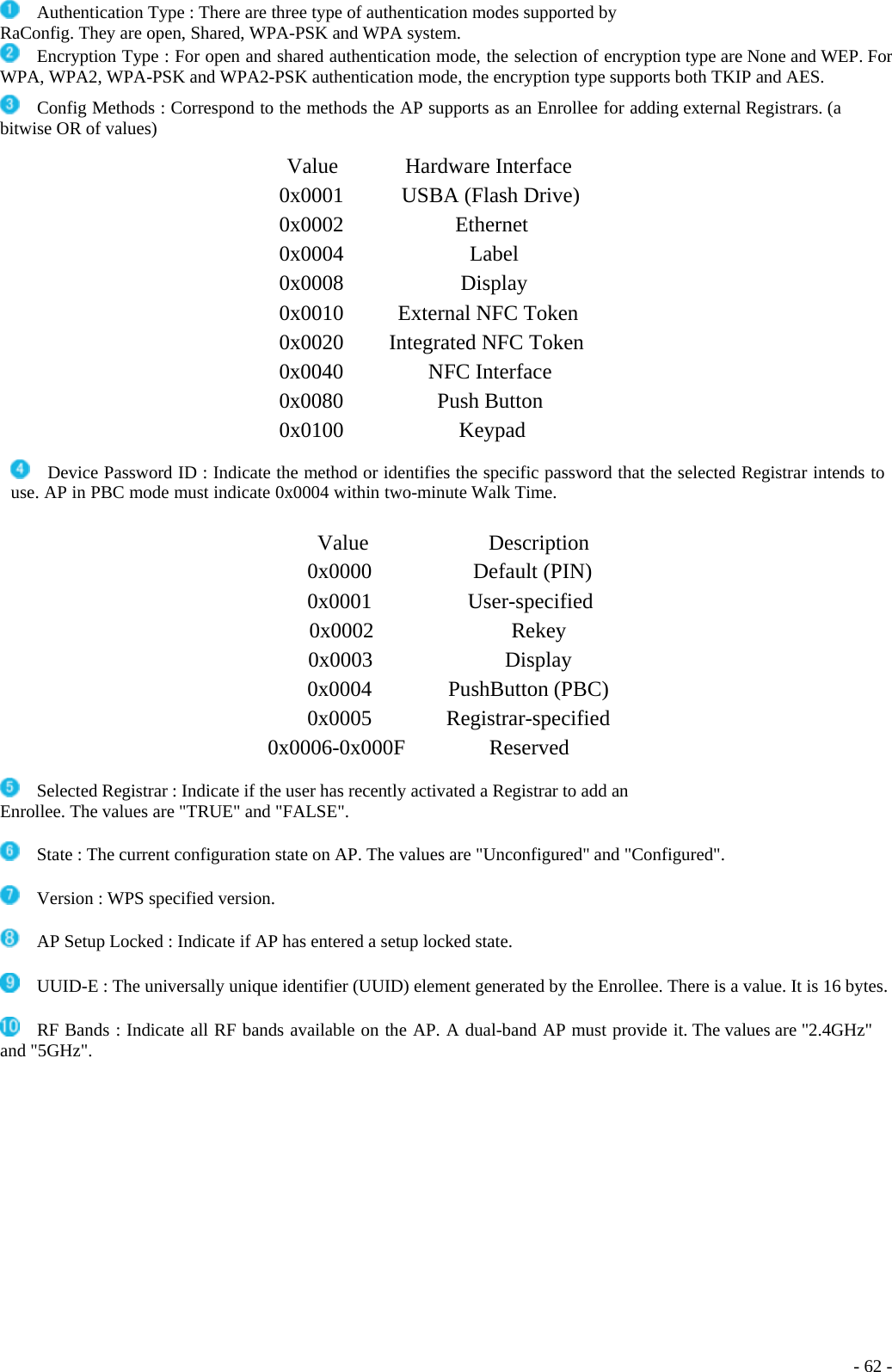
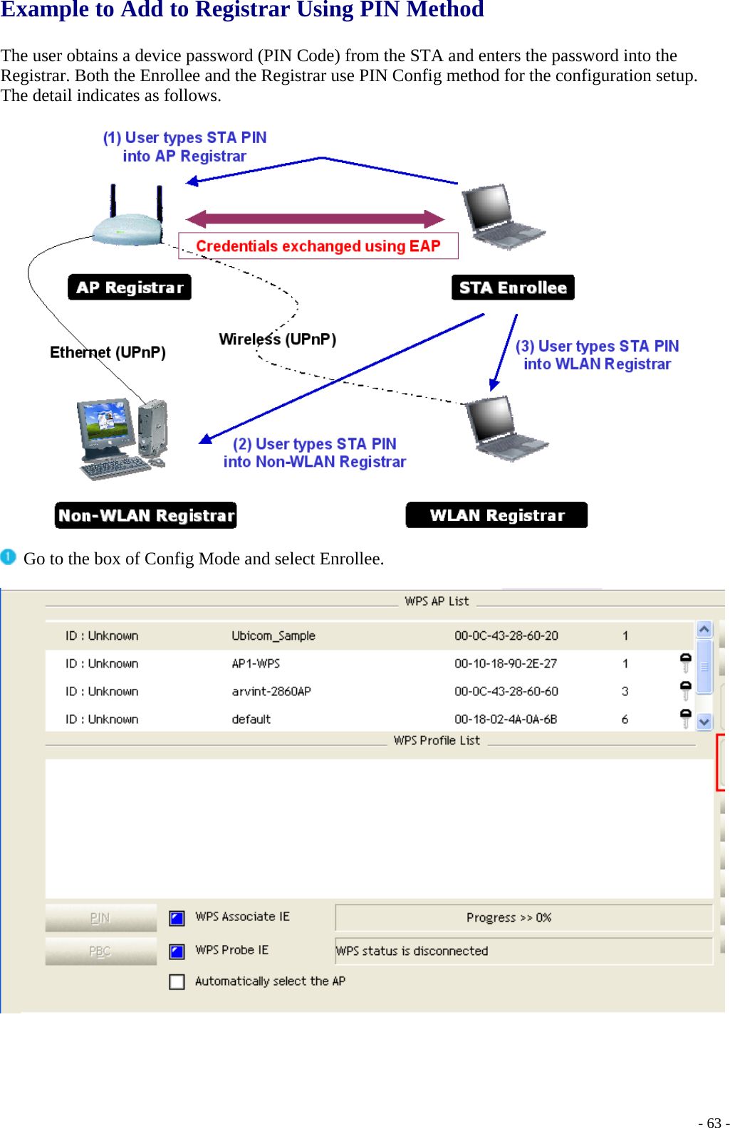
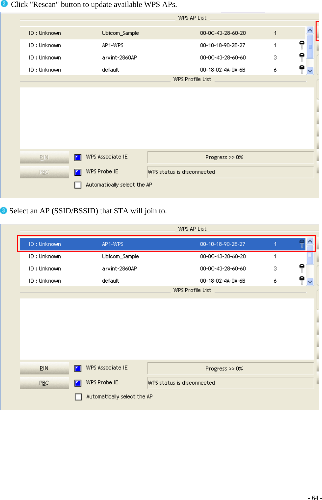
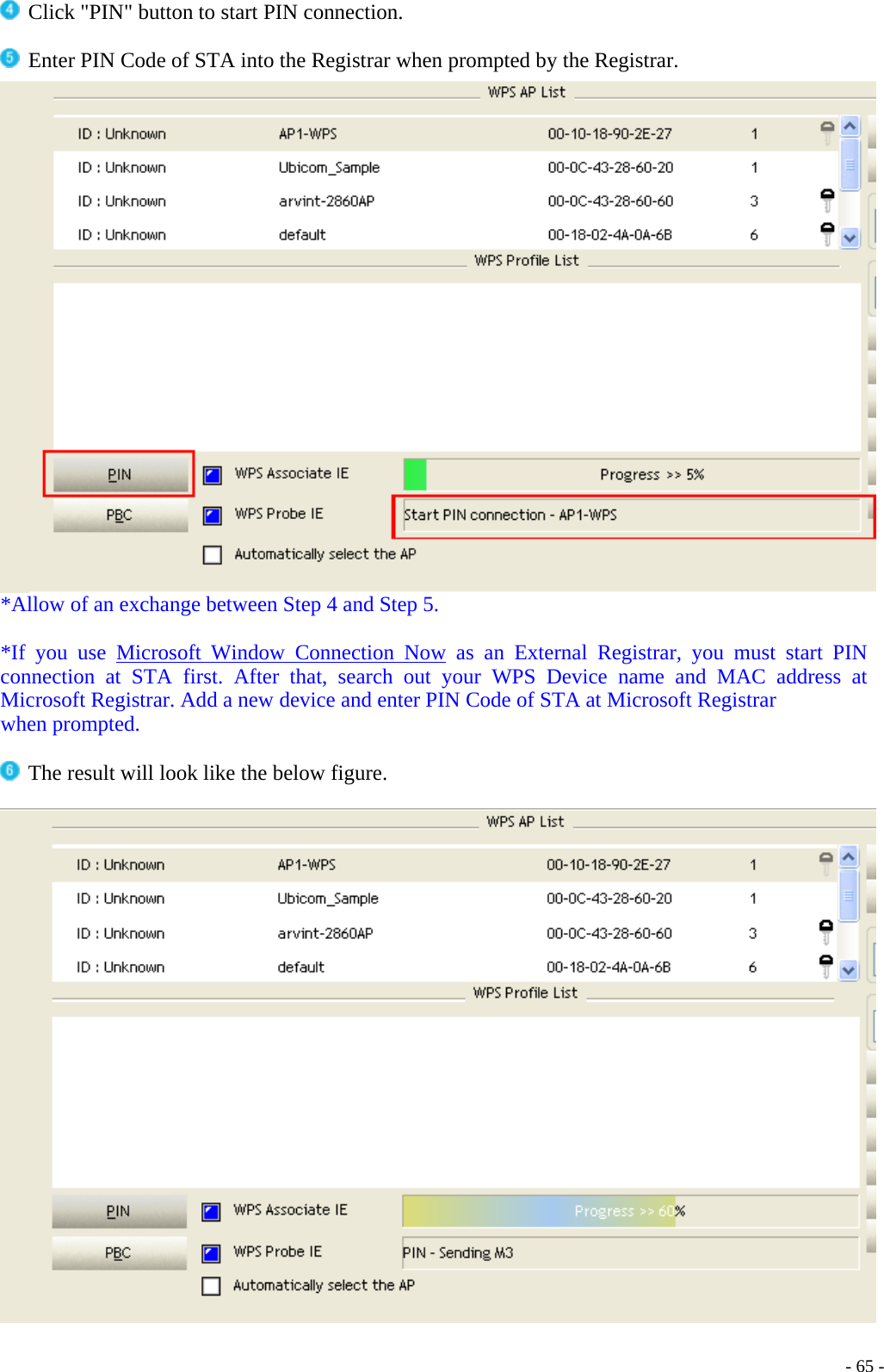
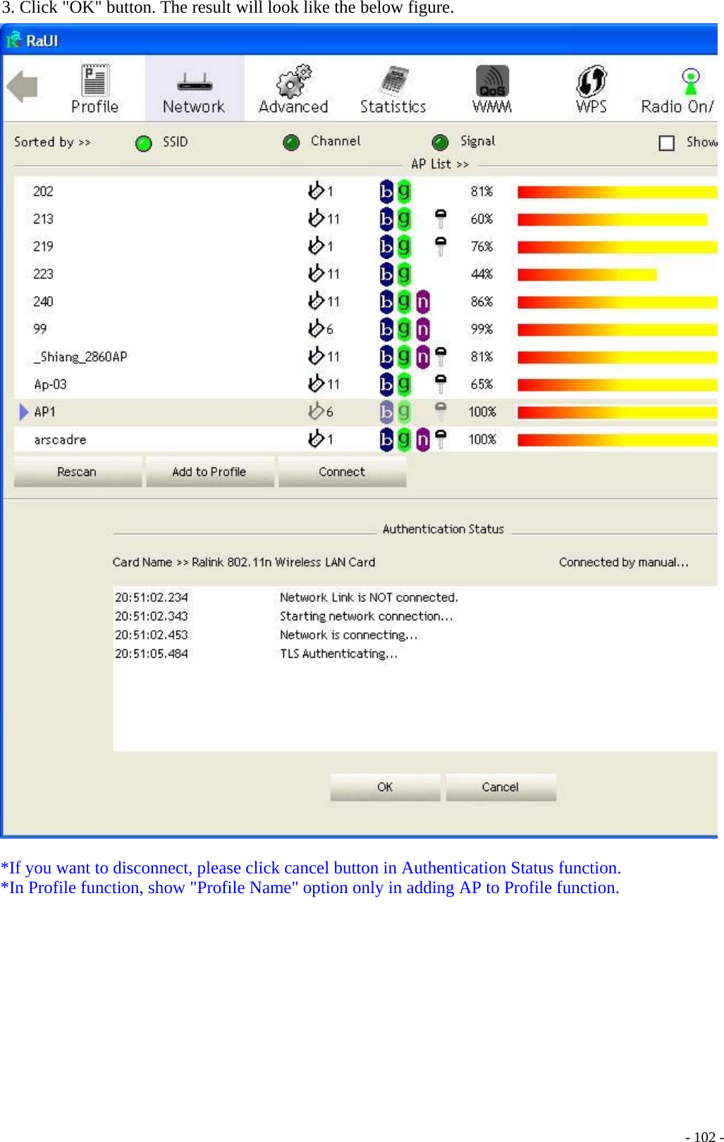
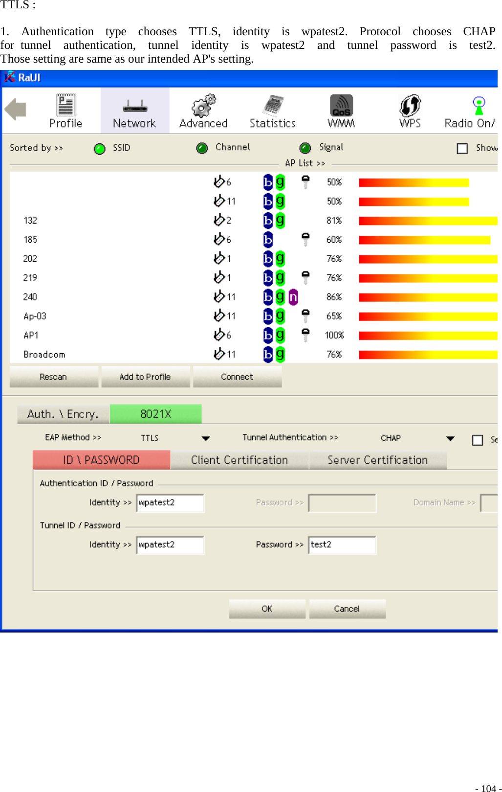
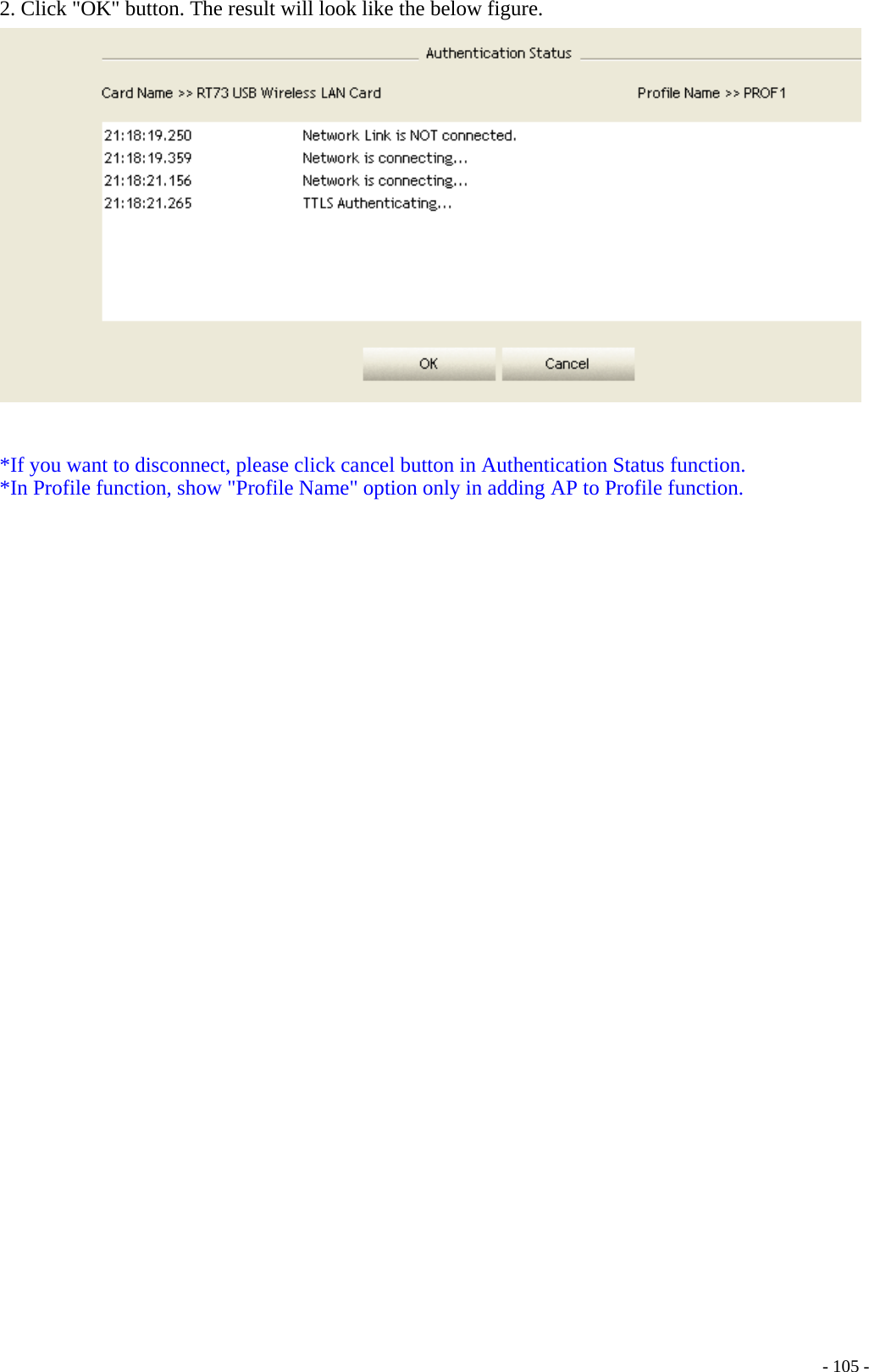
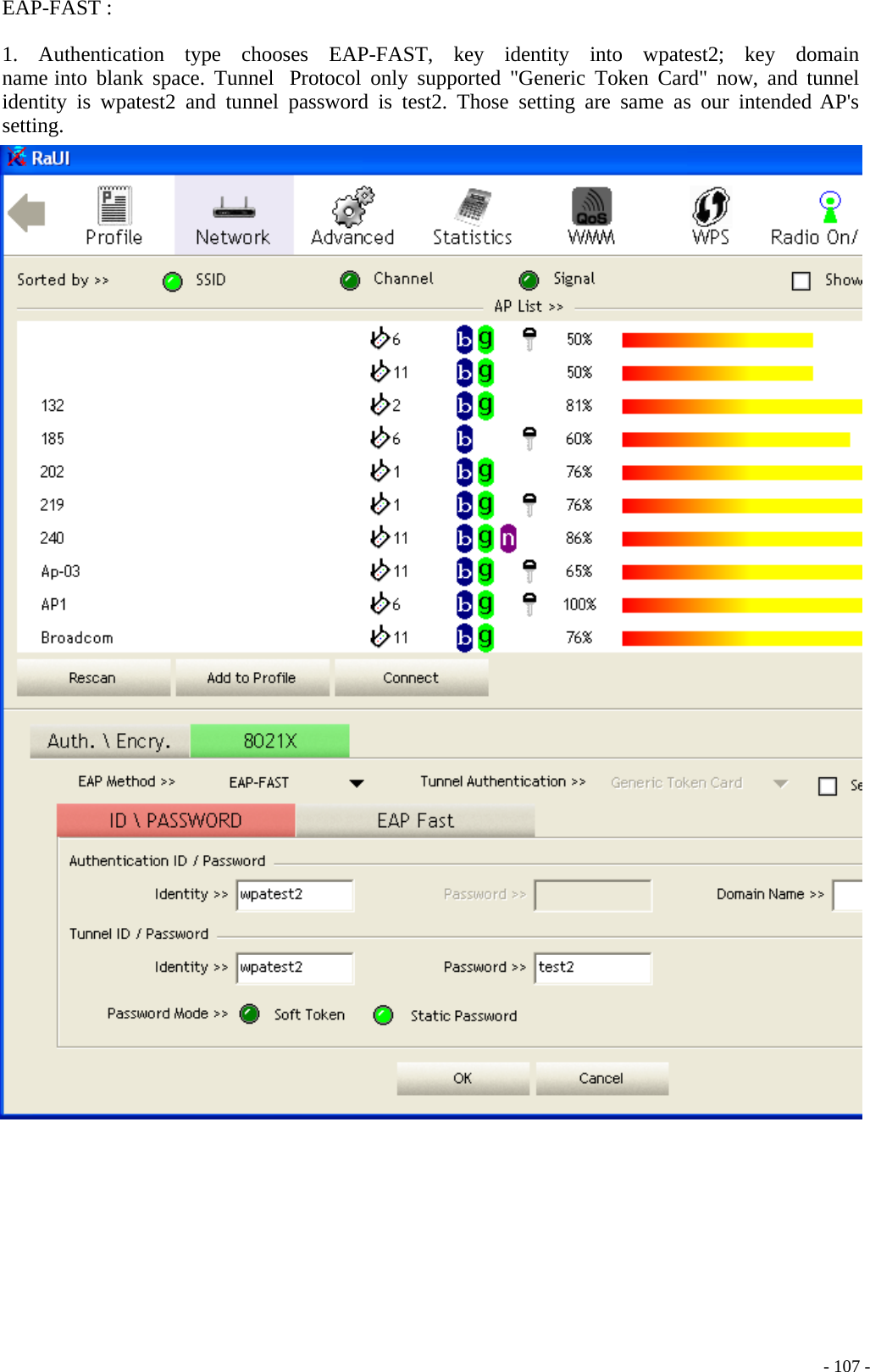
Loopcomm Technology,.Inc. 802.11b/g WLAN PCI Adapter Title

User manual

   - 1 -       Wireless LAN PCI Card                             User Manual V1.1
   - 2 -Content Introduction -----------------------------------------------------------------------------------------------3 Specifications----------------------------------------------------------------------------------------------4 Installation/ Uninstallation -----------------------------------------------------------------------------5 Ralink Wireless Utility ( RaUI ) or Windows Zero Configuration ( WZC ) ---------------- 10 Use WZC to configure wireless NIC---------------------------------------------------------------- 12 Start RaUI ----------------------------------------------------------------------------------------------- 19 Profile ------------------------------------------------------------------------------------------------------ 26 Add/Edit Profile------------------------------------------------------------------------------------------ 28 Example to Add Profile in Profile -------------------------------------------------------------------- 30 Network -------------------------------------------------------------------------------------------------- 34 Example on Adding Profile in Network------------------------------------------------------------ 42 Advanced------------------------------------------------------------------------------------------------- 46 Statistics -------------------------------------------------------------------------------------------------- 47 WMM----------------------------------------------------------------------------------------------------- 49 Example to Configure to Enable DLS (Direct Link Setup) ------------------------------------ 50 Example to Configure to Enable Wi-Fi Multi-Media ------------------------------------------- 56 Example to Configure to Enable WMM Power Save ------------------------------------------- 58 WPS------------------------------------------------------------------------------------------------------- 59 WPS Information on AP ------------------------------------------------------------------------------ 61 Example to Add to Registrar Using PIN Method ------------------------------------------------ 63 Example to Add to Registrar Using PBC Method ----------------------------------------------- 69 Example to Configure a Network/AP Using PIN or PBC Method---------------------------- 74 Link Status----------------------------------------------------------------------------------------------- 77 Auth. \ Encry. Setting - WEP/TKIP/AES---------------------------------------------------------- 78 802.1x Setting ------------------------------------------------------------------------------------------- 79 Example to Reconnect 802.1x Authenticated Connection after 802.1x Authenticated  connection Is Failed in Profile ------------------------------------------------------------------------ 82 Example to Configure Connection with WEP on ------------------------------------------------ 86 Example to Configure Connection with WPA-PSK --------------------------------------------- 90 Example to Configure Connection with WPA ---------------------------------------------------- 94 Country Channel List --------------------------------------------------------------------------------110 Acknowledgements -------------------------------------------------------------------------------------112
   - 3 -Introduction Thank you for purchasing Wireless LAN PCI Card. Wireless card is a perfect combination product of performance and cost-effectiveness. It is sincerely hoped that you can enjoy the wireless world through this solidly profiled wireless card. It provides a full solution of the IEEE 802.11b/g protocols, this solution passed the WiFi tests that are compatible with all the wireless products with WiFi logo. If you have a wireless card on hand, it means you can connect to the wireless world without any difficulty. It provides all the data rates in the IEEE 802.1b/g standards, which confines the highest data rate as 54Mbps. In addition, it rewards customers with proprietary “Turbo mode” for a better throughput as well as supports both the short and long preambles to ensure the compatibilities with legacy wireless products and new ones, saving the panic works for finding compatible products. Since the security has became one of the most important issue in the wireless society, it provides you with the full security coverage from the naïve 64/128bits Wep encryptions, second generation WPA-PSK and WPA-AES encryption, to the most advanced WPA2-PSK and WPA2-AES encryption. WPA2 is the latest security standard currently approved by WiFi standard.  Notice : The changes or modifications not expressly approved by the party responsible for compliance could void the user’s authority to operate the equipment.   IMPORTANT NOTE: To comply with the FCC RF exposure compliance requirements, no change to the antenna or the device is permitted. Any change to the antenna or the device could result in the device exceeding the RF exposure requirements and void user’s authority to operate the device. This device should be installed and operated with a minimum                   distance of 20centimeters between the radiator and your body.   The Federal Communication Commission Radio Frequency InterferenceStatement includes the following paragraph:•The equipment has been tested and found to comply with the limits for a ClassB Digital Device, pursuant to part 15 of the FCC Rules.  These limits are designedto provide reasonable protection against harmful interference in a residentialinstallation.  This equipment generates, uses and can radiate radio frequencyenergy and, if not installed and used in accordance with the instruction, may causeharmful interference to radio communication.  However, there is no grantee thatinterference will not occur in a particular installation.  If this equipment dose causeharmful interference to radio or television reception, which can be determined by turning the equipment off and on , the user is encouraged to try to correct the interference by one or more of the following measures:--Reorient or relocate the receiving antenna.--Increase the separation between the equipment and receiver.--Connect the equipment into an outlet on a circuit different from that to which the   receiver is connected.--Consult the dealer or an experienced radio/TV technician for help.The user should not modify or change this equipment without written approvalForm Loopcomm Technology,Inc..Modification could void authority to use this equipment.
   - 4 -Specifications      Interface PCI Standard 802.11b, 802.11g  OS support  98SE, WinME, Win2000, WinXP32, WinXP64, Vista32, Vista64 Data rate  1,2,5.5,11,6,8,12,18,24,36,48,54Mbps, depends on the wireless mode Frequency band  BG:2.4 ~ 2.497 GHz Operation Channel  1~11(BG) Coverage Area  Indoors: 100m (BG) Outdoors: 400m (BG) Compatibility  Fully compatible with IEEE 802.11 b/g devices Operation Mode  Infrastructure and AdHoc Security Capacity  64-bit/128-bit WEP, TKIP,WPA-AES, and WPA2-PSK,WPA2-AES Antenna External antenna LED  LED0: On: link is on. Off: link is off LED1:Blinking: data transition Turbo mode  Active when there is no other station around Power Saving mode Fast wake up and maximum power saving Other features  Dynamically adjust power for the most stable and best throughput Dynamically adjust receiving ability for the best receiving Compiled with all the main radio regulations
Installation  Hardware Installation Install Wireless LAN PCI Card (card only) into your computer PCI slot as below.           Install antenna to your Wireless LAN PCI Card as picture below.         - 5 -
Software Installation Click My Computer icon, then click DVD, then click autorun   Click Driver Installation    Click I accept the term of the license agreement ,then click Next icon.      - 6 -
Click Ralink Configuration Tool, then click Next icon.        Click Optimize for WiFi modes, then click Next icon.            - 7 -
Click Install icon.          Click Finish icon.            - 8 -
Software Uninstall Click My Computer icon, then click Add or Remove Program icon, and then click Ralink Wireless LAN icon and then click Remove icon.         Click Yes, I want to restart my computer now icon, and then Finish icon.          - 9 -
Ralink Wireless Utility ( RaUI ) or Windows Zero Configuration ( WZC )  In windows XP, it provides wireless configuration utility named "Windows Zero configuration" which provides basic configuration function for Ralink Wireless NIC. Ralink's utility ( RaUI ) provides WPA supplicant functionality. To make it easier for user to select the correct utility. RaUI will let user make the selection when it first runs after windows XP boots. Click Figure 1-1 the icon will bring up the selection window and let user make the selection.    Figure 1-1 RaUI.exe  RaUI can co-exist with WZC. When coexisting with WZC, RaUI only provides monitoring function, such as link status, network status, statistic counters, advance feature status, WMM status and WPS status. It won't interfere with WZC's configuration or profile functions. It is shown as Figure 1-2.    Figure 1-2 Select WZC or RaUI   If "Use RaConfig as Configuration utility" is selected, please jump to Section 2 on running RaUI.  If "Use Zero Configuration as Configuration utility" is selected, please continue on the section. We will explain the difference between RaUI and WZC. Figure 1-3 shows the RaUI status when WZC is active as main control utility.     - 10 -
   Figure 1-3 RaUI status with WZC active  When activating WZC, there are couple difference on RaUI status compared to that with out WZC running.   Profile button will be gray, profile function is removed since the NIC is controlled by WZC  The connect and add profile function will be gray. The reason is same as the first difference.  For all other functions provided by RaUI, please read through this document for full detail.    - 11 -
 Use WZC to configure wireless NIC   If connection is lost or not connected, the status prompt as Figure 1-4 will pop up.    Figure 1-4 status prompt of no connection   Right-click the network connection icon in task bar.    Figure 1-5 Select WZC main status   Select "View Available Wireless Networks" will pop up the dialog shown as Figure 1-6.    - 12 -
   Figure 1-6 Wireless Network Connection     Select intended AP and click "Connect" shown as Figure 1-7. Then click "Connect Anyway" shown as Figure 1-8.    - 13 -
   Figure 1-7 Select intended AP : AP1, then click "Connect"    - 14 -
  Figure 1-8 Connect AP : AP1 successfully    If you want to modify information about AP, click "Change advanced settings" shown as Figure 1-9. Then choose "Wireless Networks" label shown as Figure 1-10.    - 15 -
  Figure 1-9 Click "Change advanced settings"  Figure 1-10 Choose "Wireless Networks" label    - 16 -
   Click "Properties" shown as Figure 1-11. Then click "OK" button.   Figure 1-11 AP's properties    After filling appropriate value, click "OK" button. And the status will prompt up as Figure 1-12.    Figure 1-12 Network connection status    Click the Ralink's icon will bring up RaUI main window. User can find the surrounding APs in the list. The current connected AP will also shown with the green icon indicated as Figure 1-13. User may use the advance tab to configure more advanced features provided by Ralink's wireless NIC. For the detail on configure the advanced features, please check the Advance setting section for detail.    - 17 -
   Figure 1-13 Show connection status by using WZC to do connection    - 18 -
Start RaUI  When starting RaUI, system will connect to the AP with best signal strength without setting profile or matching profile setting. When starting RaUI, it will issue a scan command to wireless NIC. After two seconds, the AP list will updated with the result of BSS list scan. The AP list include most used fields, such as SSID, network type, channel used, wireless mode, security status and signal percentage. The arrow icon indicates the connected BSS or IBSS network. The page is shown as Figure 2-1.    Figure 2-1-1 RaUI section introduction  There are three sections in RaUI. These sections are briefly described as follow.    - 19 -
  Button Section : Include Profile page, Network page, Advanced page, Statistics page, WMM page, WPS page, About button, Radio On/Off button and Help button.    Figure 2-1-2 Button section    Figure 2-1-3 Move to the left    Figure 2-1-4 Move to the right   Function Section : Corresponding button.    Figure 2-1-5 Profile page    - 20 -
   Figure 2-1-6 Network page    Figure 2-1-7 Advance page    - 21 -
   Figure 2-1-8 Statistics page    Figure 2-1-9 WMM page    - 22 -
   Figure 2-1-10 WPS page    Figure 2-1-11 About page    Status Section : Include Link Status, Authentication Status, AP's information, Configuration and retrying the connection when authentication is failed.    - 23 -
  Figure 2-1-12 Link Status   Figure 2-1-13 Authentication Status   Figure 2-1-14 AP's Information    - 24 -
   Figure 2-1-15 Retry the connection   Figure 2-1-16 Configuration  At the mean time of starting RaUI, there is also a small Ralink icon appears within windows taskbar as Figure 2-1-15. You may double click it to bring up the main menu if you selected to close RaUI menu eariler. You may also use mouse's right button to close RaUI utility.    Figure 2-1-17 Ralink icon in system tray    - 25 -
 Besides, the small icon will change color to reflect current wireless network connection status. The status indicates as follow:    : Indicate Connected and Signal Strength is Good.  : Indicate Connected and Signal Strength is Normal.  : Indicated not connected yet.  : Indicated wireless NIC not detected.  : Indicate Connected and Signal Strength is Weak. Profile  Profile can book keeping your favorite wireless setting among your home, office, and other public  hot-spot.  You  may  save  multiple  profiles,  and  activate  the  correct  one  at  your preference. Figure 2-2-1 show the profile function.    Figure 2-2-1 Profile function  Definition of each field :    Profile Name : Name of profile, preset to PROF* (* indicate 1, 2, 3...).   SSID :    AP or Ad-hoc name.   Network Type : Network's type, including infrastructure and Ad-Hoc.   Authentication : Authentication mode.     Encryption : Encryption Type.   Use 802.1x : Whether or not use 802.1x feature.   Cannel : Channel in use for Ad-Hoc mode.   Power Save Mode : Choose from CAM (Constantly Awake Mode) or Power Saving Mode.   Tx Power : Transmit power, the amount of power used by a radio transceiver to send the signal out.   RTS Threshold : User can adjust the RTS threshold number by sliding the bar or key in the value directly.  Fragment Threshold : User can adjust the Fragment threshold number by sliding the bar or key in the value directly.    - 26 -
 Icons and buttons :  Indicate connection is successful on currently activated profile.  Indicate connection is failed on currently activated profile.  Indicate network type is infrastructure mode.  Indicate network type is Ad-hoc mode.  Indicate security-enabled wireless network.  Add a new profile.  Edit an existing profile.  Delete an existing profile.  Activate selected profile.  Show the information of Status Section.  Hide the information of Status Section.    - 27 -
Add/Edit Profile  There are three methods to open Profile Editor form.   You can open it from "Add to Profile" button in Site Survey function.  You can open it from "Add" button in Profile function.   You can open it from "Edit" button in Profile function.      Figure 2-2-2 Configuration    Profile Name : User can chose name for this profile, or use default name defined by system.    SSID : User can key in the intended SSID name or use pull down menu to select from available APs.    Power Save Mode : Choose from CAM Constantly Awake Mode for Power Saving Mode.    - 28 -
   Network Type : There are two types, infrastructure and 802.11 Ad-hoc mode. Under Ad- hoc mode, user can also choose the preamble type, the available preamble type includes auto and long. In addition to that, the channel field will be available for setup in Ad-hoc mode.   RTS Threshold : User can adjust the RTS threshold number by sliding the bar or key in the value directly. The default value is 2347.    Fragment Threshold : User can adjust the Fragment threshold number by sliding the bar or key in the value directly. The default value is 2346.    Channel : Only available for setting under Ad-hoc mode. User can choose the channel frequency to start their Ad-hoc network.    Authentication Type : There are 7 type of authentication modes supported by RaUI. They are open, Shared, LEAP, WPA and WPA-PSK, WPA2 and WPA2-PSK.    Encryption Type : For open and shared authentication mode, the selection of encryption type are None and WEP. For WPA, WPA2, WPA-PSK and WPA2-PSK authentication mode, the encryption type supports both TKIP and AES.     - 29 -  802.1x Setting : This is introduced in the topic of "Section 3-2 : 802.1x Setting".    WPA Pre-shared Key : This is the shared secret between AP and STA. For WPA-PSK and WPA2-PSK authentication mode, this field must be filled with character longer than 8 and less than 32 length.    WEP Key : Only valid when using WEP encryption algorithm. The key must matched AP's key. There are several formats to enter the keys.  1.    Hexadecimal - 40bits : 10 Hex characters.  2.    Hexadecimal - 128bits : 26Hex characters.  3.    ASCII - 40bits : 5 ASCII characters.  4.    ASCII - 128bits : 13 ASCII characters.
 Example to Add Profile in Profile   Click Add in Profile function.       - 30 -
 Add Profile page will pop up.     - 31 -
 Change profile name to what you want to connect. Pull down the ssid and select one intended AP. The AP list is the result of last Network.     - 32 -
 Then, you can see the profile which you set appear in the profile list. Click "Activate". Activate the profile setting.     - 33 -
Network  Under the Network function, system will display the information of surrounding APs from last scan result. List informations include SSID, BSSID, Signal, Channel, Encryption algorithm, Authentication and Network type as Figure 2-3-1-1 shown.    Figure 2-3-1-1 Network fuction  Definition of each field :   SSID : Name of BSS or IBSS network.   Network Type : Network type in use, Infrastructure for BSS, Ad-Hoc for IBSS network.   Channel : Channel in use.   Wireless Mode : AP support wireless mode. It may support 802.11a, 802.11b, 802.11g or 802.11n wireless mode.   Security-Enable : Whether AP provides security-enabled wireless network.   Signal : Receive signal strength of specified network.      - 34 -
Icons and buttons : Indicate connection is successful. Indicate network type is infrastructure mode. Indicate network type is Ad-hoc mode.    - 35 - Indicate security-enabled wireless network.  Indicate 802.11a wireless mode. mode.   Indicate 802.11b wireless. Indicate 802.11g wireless mode. Indicate 802.11n wireless mode    Indicate that AP list are sorted by SSID, Channel or Signal.  Command to connect to the selected network.  Issue an rescan command to wireless NIC to update information on surrounding wireless network.  Add the selected AP to Profile setting. It will bring up profile page and save user's setting to a new profile.  Show the information of Status Section.  Hide the information of Status Section.
Connected network :   When RaUI first ran, it will select the best AP to connect automatically.   If user wants to connect to other AP. He can click "Connect" button for the intended AP to make connection.   If the intended network has encryption other than "Not Use", RaUI will bring up the security page and let user input the appropriate information to make the connection. Please refer to example on how to fill the security information.  When you double click on the intended AP, you can see AP's detail information.  AP's detail information divide into three parts. They are General, WPS, CCX information and 802.11n ( 802.11n button only exists for the AP supported N mode ). The introduction is as follow :    - 36 -
  General information contain AP's ssid, MAC address, authentication type, encryption type, channel, network type, beacon interval, signal strength and supported rates. It shows as Figure 2-3-1-2.     Figure 2-3-1-2 General informaion about AP's detal information    - 37 -
   WPS information contain authentication type, encryption type, config methods, device password id, selected registrar, state, version, AP setup locked, UUID-E and RF bands as Figure 2-3-1-3. The introduction indicates as follow :    Authentication Type : There are three type of authentication modes supported by RaConfig. They are open, Shared, WPA-PSK and WPA system.   Encryption Type : For open and shared authentication mode, the selection of encryption type are None and WEP. For WPA, WPA2, WPA-PSK and WPA2-PSK authentication mode, the encryption type supports both TKIP and AES.  Config Methods : Correspond to the methods the AP supports as an Enrollee for adding external Registrars. (a bitwise OR of values)  Value Hardware Interface 0x0001 USBA (Flash Drive) 0x0002 Ethernet 0x0004 Label 0x0008 Display 0x0010  External NFC Token 0x0020  Integrated NFC Token 0x0040 NFC Interface 0x0080 Push Button 0x0100 Keypad     Device Password ID : Indicate the method or identifies the specific password that the selected Registrar intends to use. AP in PBC mode must indicate 0x0004 within two-minute Walk Time.   Value Description 0x0000 Default (PIN) 0x0001 User-specified 0x0002 Rekey 0x0003 Display 0x0004 PushButton (PBC) 0x0005 Registrar-specified 0x0006-0x000F Reserved     Selected Registrar : Indicate if the user has recently activated a Registrar to add an Enrollee. The values are "TRUE" and "FALSE".    State : The current configuration state on AP. The values are "Unconfigured"    and "Configured".   Version : WPS specified version.   AP Setup Locked : Indicate if AP has entered a setup locked state.   UUID-E : The universally unique identifier (UUID) element generated by the Enrollee. There is a value. It is 16 bytes.   RF Bands : Indicate all RF bands available on the AP. A dual-band AP must provide it. The values are "2.4GHz" and "5GHz".    - 38 -
   Figure 2-3-1-3 WPS information about AP's detail information    - 39 -
 CCX information contains CCKM, Cmic and Ckip information. It shows as Figure 2-3-1-4.    Figure 2-3-1-4 CCX information about AP's detail information    - 40 -
 802.11n information contains some related 802.11n information. It shows as Figure 2-3-1-5.    Figure 2-3-1-5 802.11n information    - 41 -
Example on Adding Profile in Network   Select the intended network from AP list in Network function.       - 42 -
 Click "Add to Profile".      - 43 -
 System will pop up Add Profile windows. You can change profile name which you like most.     - 44 -
 Then, you can see the profile which you set appear in the profile list. Click "Activate". Activate the profile setting.     - 45 -
Advanced  Figure 2-4 shows Advance function of RaUI.    Figure 2-4 Advance function    Wireless mode : Select wireless mode. 802.11 B only, 802.11 A only, 802.11 B/G mix, 802.11 B/G/N mix, 802.11 A/B/G mix, and 802.11 A/B/G/N mix modes are supported. (802.11 A/B/G mix selection item only exists for A/B/G adapter ; 802.11 B/G/N mix selection item only exists for B/G/N adapter ; 802.11 A/B/G/N mix selection item only exists for A/B/G/N adapter)  Wireless Protection : User can choose from Auto, On, and Off.   (only 802.11n adapter don't support.)  Auto : STA will dynamically change as AP announcement.     On : Always send frame with protection.  Off : Always send frame without protection.  TX Rate : Manually force the Transmit using selected rate. Default is auto. (802.11n wireless card don't support TX Rate now)  Enable TX Burst : Ralink's proprietary frame burst mode.   Enable TCP Window Size : Enhance throughput.  Fast Roaming at : fast to roaming, setup by transmit power.  Select Your Country Region Code : eight countries to choose. Country channel list : Country channel list. (11A ListBox only shows for A/B/G adapter.)  Show Authentication Status Dialog : When you connect AP with authentication, choose whether show "Authentication Status Dialog" or not. Authentication Status Dialog display the process about 802.1x authentication.  Enable CCX (Cisco Compatible eXtensions) : support Cisco Compatible Extensions function.  LEAP turn on CCKM.  Enable Radio Measurement : can channel measurement every 0~2000 milliseconds.  Apply the above changes.      - 46 -
Icons and buttons:  Show the information of Status Section.   Hide the information of Status Section.  Statistics  Statistics page displays the detail counter information based on 802.11 MIB counters. This page translates that MIB counters into a format easier for user to understand. Figure 2-5-1 shows the detail page layout.    Figure 2-5-1 Statistics function  Transmit Statistics :     Frames Transmitted Successfully : Frames successfully sent.   Frames Fail To Receive ACK After All Retries : Frames failed transmit after hitting retry limit.    - 47 -
  RTS Frames Successfully Receive CTS : Successfully receive CTS after sending RTS frame.  RTS Frames Fail To Receive CTS : Failed to receive CTS after sending RTS.   Frames Retransmitted Successfully : Successfully retransmitted frames numbers.   Reset counters to zero.  Receive Statistics :     Frames Received Successfully : Frames received successfully.   Frames Received With CRC Error : Frames received with CRC error.   Frames Dropped Due To Out-of-Resource : Frames dropped due to resource issue.   Duplicate Frames Received : Duplicate received frames.   Reset counters to zero. Icons and buttons: Show the information of Status Section. Hide the information of Status Section.    - 48 -
WMM  Figure 2-6-1 shows WMM function of RaUI. It involves "WMM Enable", "WMM - Power Save Enable" and DLS setup. The introduction indicates as follow :     Figure 2-6-1 WMM function  WMM Enable : Enable Wi-Fi Multi-Media. The setting method follows Section 2-6-2. WMM - Power Save Enable : Enable WMM Power Save. The setting method follows Section 2-6-3.  Direct Link Setup Enable : Enable DLS (Direct Link Setup). The setting method follows Section 2-6-4.  Icons and buttons:    - 49 - Show the information of Status Section. Hide the information of Status Section.
 Example to Configure to Enable DLS (Direct Link Setup)    Click "Direct Link Setup Enable"       - 50 -
 Change to "Network" function. And add a AP that supports DLS features to a Profile. The result will look like the below figure in Profile page.   The setting of DLS indicates as follow :   Fill in the blanks of Direct Link with MAC Address of STA. The STA must conform to two conditions as follow :  1. Connect with the same AP that support DLS features.  2. Have to enable DLS.    - 51 -
   Timeout Value represents that it disconnect automatically after some seconds. The value is integer. The integer must be between 0~65535. It represents that it always connects if the value is zero. Default value of Timeout Value is 60 seconds.       - 52 -
 Click "Apply" button. The result will look like the below figure.   Describe "DLS Status" as follow :   As the up figure, after configuring DLS successfully, show MAC address of the opposite side and Timeout Value of setting in "DLS Status". In "DLS Status" of the opposite side, it shows MAC address of myself and Timeout Value of setting.   Display the values of "DLS Status" to "Direct Link Setup" as follow :  1.    In "DLS Status" select a direct link STA what you want to show it's values in "Direct Link Setup".       - 53 -
2.    Double click. And the result will look like the below figure.    Disconnect Direct Link Setup as follow :  1.    Select a direct link STA.       - 54 -
2.    Click "Tear Down" button. The result will look like the below figure.     - 55 -
Example to Configure to Enable Wi-Fi Multi-Media  If you want to use "WMM-Power Save" or "Direct Link" you must enable WMM. The setting method of enabling WMM indicates as follows:   Click "WMM Enable".       - 56 -
  Change to "Network" function. And add a AP that supports WMM features to a Profile. The result will look like the below figure in Profile page.     - 57 -
Example to Configure to Enable WMM Power Save     Click "WMM-Power Save Enable".       Please select which ACs you want to enable. The setting of enabling WMM-Power Save is successfully.      - 58 -
WPS  Figure 2-7-1 shows WPS function of RaUI. The introduction indicates as follow:    Figure 2-7-1 WPS function    - 59 -
  WPS Configuration : The primary goal of Wi-Fi Protected Setup (Wi-Fi Simple Configuration) is to simplify the security setup and management of Wi-Fi networks. Ralink STA as an Enrollee or external Registrar supports the configuration setup using PIN configuration method or PBC configuration method through an internal or external Registrar.  WPS AP List : Display the information of surrounding APs with WPS IE from last scan result. List information include SSID, BSSID, Channel, ID (Device Password ID), Security- Enabled.  Rescan : Issue a rescan command to wireless NIC to update information on surrounding wireless network.  Information : Display the information about WPS IE on the selected network. List information include Authentication Type, Encryption Type, Config Methods, Device Password ID, Selected Registrar, State, Version, AP Setup Locked, UUID-E and RF Bands. It's detail follows WPS Information on AP.  PIN Code : 8-digit numbers. It is required to enter PIN Code into Registrar using PIN method. When STA is Enrollee, you can use "Renew" button to re-generate new PIN Code.  Config Mode : Our station role-playing as an Enrollee or an external Registrar.  Table of Credentials: Display all of credentials got from the Registrar. List information include SSID, MAC Address, Authentication and Encryption Type. If STA Enrollee, credentials are created as soon as each WPS success. If STA Registrar, RaUI creates a new credential with WPA2-PSK/AES/64Hex-Key and doesn't change until next switching to STA Registrar.  Control items on credentials 1. Detail : Information about Security and Key in the credential. 2. Connect : Command to connect to the selected network inside credentials. The active selected credential is as like as the active selected Profile. 3. Rotate : Command to rotate to connect to the next network inside credentials. 4. Disconnect : Stop WPS action and disconnect this active link. And then select the last profile at the Profile Page of RaUI if exist. If there is an empty profile page, the driver will select any non-security AP. 5. Export Profile: Export all credentials to Profile. 6. Delete : Delete an existing credential. And then select the next credential if exist. If there is an empty credential, the driver will select any non-security AP.  PIN : Start to add to Registrar using PIN configuration method. If STA Registrar, remember that enter PIN Code read from your Enrollee before starting PIN.  PBC : Start to add to AP using PBC configuration method. *When you click PIN or PBC, please don't do any rescan within two-minute connection. If you want to abort this setup within the interval, restart PIN/PBC or press Disconnect to stop WPS action.  WPS associate IE : Send the association request with WPS IE during WPS setup. It is optional for STA.  WPS probe IE : Send the probe request with WPS IE during WPS setup. It is optional for STA.  Progress Bar : Display rate of progress from Start to Connected status.  Status Bar: Display currently WPS Status.  Automatically select the AP: Start to add to AP by using to select the AP automatically in PIN method. **There are examples in    - 60 -section 2-7-3(PIN Enrollee Setup), section 2-7-4(PBC Enrollee Setup) and section 2-7-5(Registrar Configures and AP)** Icons and buttons: Show the information of Status Section. Hide the information of Status Section.
WPS Information on AP  WPS information contain authentication type, encryption type, config methods, device password id, selected registrar, state, version, AP setup locked, UUID-E and RF bands. The introduction indicates as follow :      - 61 -
     Authentication Type : There are three type of authentication modes supported by RaConfig. They are open, Shared, WPA-PSK and WPA system.     Encryption Type : For open and shared authentication mode, the selection of encryption type are None and WEP. For WPA, WPA2, WPA-PSK and WPA2-PSK authentication mode, the encryption type supports both TKIP and AES.     Config Methods : Correspond to the methods the AP supports as an Enrollee for adding external Registrars. (a bitwise OR of values)  Value Hardware Interface 0x0001 USBA (Flash Drive) 0x0002 Ethernet 0x0004 Label 0x0008 Display 0x0010  External NFC Token 0x0020  Integrated NFC Token 0x0040 NFC Interface 0x0080 Push Button 0x0100 Keypad      Device Password ID : Indicate the method or identifies the specific password that the selected Registrar intends to use. AP in PBC mode must indicate 0x0004 within two-minute Walk Time.   Value Description 0x0000 Default (PIN) 0x0001 User-specified 0x0002 Rekey 0x0003 Display 0x0004 PushButton (PBC) 0x0005 Registrar-specified 0x0006-0x000F Reserved      Selected Registrar : Indicate if the user has recently activated a Registrar to add an Enrollee. The values are "TRUE" and "FALSE".      State : The current configuration state on AP. The values are "Unconfigured" and "Configured".      Version : WPS specified version.      AP Setup Locked : Indicate if AP has entered a setup locked state.      UUID-E : The universally unique identifier (UUID) element generated by the Enrollee. There is a value. It is 16 bytes.      RF Bands : Indicate all RF bands available on the AP. A dual-band AP must provide it. The values are "2.4GHz" and "5GHz".    - 62 -
 Example to Add to Registrar Using PIN Method   The user obtains a device password (PIN Code) from the STA and enters the password into the Registrar. Both the Enrollee and the Registrar use PIN Config method for the configuration setup. The detail indicates as follows.     Go to the box of Config Mode and select Enrollee.      - 63 -
  Click "Rescan" button to update available WPS APs.    Select an AP (SSID/BSSID) that STA will join to.       - 64 -
  Click "PIN" button to start PIN connection.   Enter PIN Code of STA into the Registrar when prompted by the Registrar.  *Allow of an exchange between Step 4 and Step 5.  *If you use Microsoft Window Connection Now as an External Registrar, you must start PIN connection at STA first. After that, search out your WPS Device name and MAC address at Microsoft Registrar. Add a new device and enter PIN Code of STA at Microsoft Registrar when prompted.   The result will look like the below figure.      - 65 -
  Configured and got one or multiple credential(s).   Then connect successfully. The result will look like the below figure.      - 66 -
  Click "Detail" button.   You will look like the below figure.    *If Credential#1 is reliable and present, system will connect with Credential#1. On the contrary, system will auto rotate to the next existed credential.  *Also you can click "Rotate" button. Command to rotate to the next credential you want to use.  Describe "WPS Status Bar" - "PIN - xxx" as follow :      - 67 -
  Asuccessful PIN Configuration : Start PIN connection - SSID ~> Begin associating to WPS AP ~> Associated to WPS AP ~> Sending EAPOL-Start ~> Sending EAP-Rsp (ID) ~> Receive EAP-Req (Start) ~> Sending M1 ~> Received M2 ~> (Received M2D ~> Sending EAP-Rsp (ACK)) ~> Sending M3 ~> Received M4 ~> Sending M5 ~> Received M6 ~> Sending M7 ~> Received M8 ~> Sending EAP-Rsp(Done) ~> Configured ~> WPS status is disconnected ~> WPS status is connected successfully-SSID   WPS configuration doesn't complete after two-minute connection : WPS Eap process failed.  When Errors occur within two-minute connection, the WPS status bar might report on "WPS Eap process failed".  Error messages might be :  1. Receive EAP with wrong NONCE.  2. Receive EAP without integrity.  3. Error PIN Code.  4. An inappropriate EAP-FAIL received.    - 68 -
Example to Add to Registrar Using PBC Method   The PBC method requires the user to press a PBC button on both the Enrollee and the Registrar within a two-minute interval called the Walk Time. If only one Registrar in PBC mode, which PBC mode is obtained from ID 0x0004, is found after a complete scan, the Enrollee can immediately begin running the Registration Protocol.  If the Enrollee discovers more than one Registrar in PBC mode, it MUST abort its connection attempt at this scan and continue searching until two-minute timeout.  *Before you press PBC on STA and candidate AP. Make sure all of APs aren't PBC mode or APs using PBC mode have left their Walk Time.     Go to the box of Config Mode and select Enrollee.       - 69 -
 Click PBC to start PBC connection.  Push PBC on AP.    *Allow of an exchange between Step 2 and Step 3.   Then it can be shown "Rcanning AP" as the below figure.       - 70 -
 When finding only one AP, join it.   Check WPS Information on available WPS APs       - 71 -
 Configured and got one or multiple credential(s).   Then connect successfully. The result will look like the below figure.     Describe "WPS Status Bar" -    "PBC - xxx" as follow :     - 72 -
 A successful PBC Configuration :  Start PBC connection ~> Scanning AP ~> Begin associating to WPS AP ~> Associated to WPS AP ~> Sending EAPOL-Start ~> Sending EAP-Rsp (ID) ~> Receive EAP-Rsp (Start) ~> Sending M1 ~> Received M2 ~> Sending M3 ~> Received M4 ~> Sending M5 ~> Received M6 ~> Sending M7 ~> Received M8 ~> Sending EAP-Rsp (Done) ~> Configured ~> WPS status is disconnected ~> WPS status is connected successfully-SSID   No PBC AP available :  Scanning AP ~> No PBC AP available ~> Scanning AP ~> No PBC AP available ~>...   Too Many PBC AP available :  Scanning AP ~> Too Many PBC AP available ~> Scanning AP ~> Too Many PBC AP available ~>...   WPS configuration doesn't complete after two-minute connection : WPS Eap process failed.  When Errors occur within two-minute connection, the WPS status bar might report on" WPS Eap process failed".  Error messages might be :  1. Receive EAP with wrong NONCE.  2. Receive EAP without integrity.  3. An inappropriate EAP-FAIL received.  Describe "Multiple PBC session overlaps" as follow :   Dual bands : AP1 is a G-Band AP using PBC mode. (ID = 0x0004) AP2 is a A-Band AP using PBC mode. (ID = 0x0004) They have the same UUID-E. STA would regard these two APs as a dual-radio AP and select one band to connect.   Different UUID-E :  AP1 is a G-Band AP using PBC mode. (ID = 0x0004) AP2 is a G-Band AP using PBC mode. (ID = 0x0004) They have the different UUID-E. STA would regard these two APs as two different APs and wait until only one PBC AP is available.    - 73 -
Example to Configure a Network/AP Using PIN or PBC Method     Go to the box of Config Mode and select Registrar.      - 74 -
 Enter "Detail" of the credential and change configurations (SSID, Authentication, Encryption and Key) manually if need.     If PIN configuration setup, enter Pin Code read from your Enrollee.       - 75 - Start PIN or PBC. The following procedures are as similar as section 2-7-3(PIN Enrollee Setup) or section 2-7-4(PBC Enrollee Setup),   If your AP Enrollee has been configured before WPS process, the credential you set in advance will be updated to AP itself. Otherwise, after a successful registration, the AP Enrollee will be re-configured with the new parameters, and STA Registrar will connect to the AP Enrollee with these new parameters.
   Describe "WPS Status Bar" - "PIN - xxx" as follow :  A successful PIN Configuration :  Start PIN connection - SSID ~> Begin associating to WPS AP ~> Associated to WPS AP ~> Sending EAPOL-Start ~> Sending EAP-Rsp (ID) ~> Receive M1 ~> Sending M2 ~> Receive M3 ~> Sending M4 ~> Receive M5 ~> Sending M6 ~> Receive M7 ~> Sending M8 ~> Receive EAP Rsp (Done) ~> Sending EAP Rsp (ACK) ~> Configured ~> WPS status is disconnected ~> WPS status is connected successfully-SSID  Describe "WPS Status Bar" -    "PBC - xxx" as follow :  A successful PBC Configuration :  Start PBC connection ~> Scanning AP ~> Begin associating to WPS AP ~> Associated to WPS AP ~> Sending EAPOL-Start ~> Sending EAP-Rsp (ID) ~> Receive M1 ~> Sending M2 ~> Receive M3 ~> Sending M4 ~> Receive M5 ~> Sending M6 ~> Receive M7 ~> Sending M8 ~> Receive EAP Rsp (Done) ~> Sending EAP Rsp (ACK) ~> Configured ~> WPS status is disconnected ~> WPS status is connected successfully-SSID    - 76 -
Link Status  Figure 2-9 is the link status page, it displays the detail information current connection.    Figure 2-9 Link Status function   Status : Current connection status. If no connection, if will show Disconnected. Otherwise, the SSID and BSSID will show here.  Extra Info : Display link status in use.  Channel : Display current channel in use.  Authentication : Authentication mode in use.   Encryption : Encryption type in use.  Network Type : Network type in use.  IP Address : IP address about current connection.   Sub Mask : Sub mask about current connection.  Default Gateway :    Default gateway about current connection.  Link Speed : Show current transmit rate and receive rate.  Throughout : Display transmits and receive throughput in unit of Mbps.  Link Quality : Display connection quality based on signal strength and TX/RX packet error rate.  Signal Strength 1 : Receive signal strength 1, user can choose to display as percentage or dBm format.  Signal Strength 2 : Receive signal strength 2, user can choose to display as percentage or dBm format.  Signal Strength 3 : Receive signal strength 3, user can choose to display as percentage or dBm format.  Noise Strength : Display noise signal strength.  HT : Display current HT status in use, containing BW, GI,    MCS, SNR0, and SNR1 value. (Show the information only for 802.11n wireless card.)    - 77 -
Auth. \ Encry. Setting - WEP/TKIP/AES  Auth. \    Encry.    Setting, shown as Figure 3-1.    Figure 3-1 Auth. \  Encry.  Setting   Authentication Type : There are 7 type of authentication modes supported by RaUI. They are open, Shared, LEAP, WPA and WPA-PSK, WPA2 and WPA2-PSK.   Encryption Type : For open and shared authentication mode, the selection of encryption type are None and WEP. For WPA, WPA2, WPA-PSK and WPA2-PSK authentication mode, the encryption type supports both TKIP and AES.     - 78 - 8021X : This is introduced in the topic of Section 3-2.   WPA Pre-shared Key : This is the shared secret between AP and STA. For WPA-PSK and WPA2-PSK authentication mode, this field must be filled with character longer than 8 and less than 32 length.   WEP Key : Only valid when using WEP encryption algorithm. The key must matched AP's key. There are several formats to enter the keys.   Hexadecimal - 40bits : 10 Hex characters.   Hexadecimal - 128bits : 32Hex characters.  ASCII - 40bits : 5 ASCII characters.  ASCII - 128bits : 13 ASCII characters.  **Powered by Meetinghouse.
802.1x Setting  802.1x is a authentication for "WPA" and "WPA2" certificate to server.    Authentication type :    PEAP : Protect Extensible Authentication Protocol. PEAP transport securely authentication data by using tunneling between PEAP clients and an authentication server. PEAP can authenticate wireless LAN clients using only server-side certificates, thus simplifying the implementation and administration of a secure wireless LAN.   TLS/Smart Card : Transport Layer Security. Provides for certificate-based and mutual authentication of the client and the network. It relies on client-side and server-side certificates to perform authentication and can be used to dynamically generate user-based and session-based WEP keys to secure subsequent communications between the WLAN client and the access point.   TTLS : Tunneled Transport Layer Security. This security method provides for certificate- based, mutual authentication of the client and network through an encrypted channel. Unlike EAP-TLS, EAP-TTLS requires only server-side certificates.   EAP-FAST : Flexible Authentication via Secure Tunneling. It was developed by Cisco. Instead of using a certificate, mutual authentication is achieved by means of a PAC (Protected Access Credential) which can be managed dynamically by the authentication server. The PAC can be provisioned (distributed one time) to the client either manually or automatically. Manual provisioning is delivery to the client via disk or a secured network distribution method. Automatic provisioning is an in-band, over the air, distribution. For tunnel authentication, only support "Generic Token Card" authentication now.   LEAP : Light Extensible Authentication Protocol. It is an EAP authentication type used primarily in Cisco Aironet WLANs. It encrypts data transmissions using dynamically generated WEP keys, and supports mutual authentication.   MD5-Challenge: Message Digest Challenge. Challenge is an EAP authentication type that provides base-level EAP support. It provides for only one-way authentication - there is no mutual authentication of wireless client and the network. Session Resumption : user can choose "Disable" and "Enable". Tunnel      - 79 -
Authentication :   Protocol : Tunnel protocol, List information include "EAP-MSCHAP v2", "EAP-TLS/Smart card", "Generic Token Card", "CHAP", "MS-CHAP", "MS-CHAP-V2", "PAP" and "EAP- MD5".   Tunnel Identity : Identity for tunnel.   Tunnel Password : Password for tunnel.  - ID \ PASSWORD -    Authentication ID / Password : Identity, password and domain name for server. Only "EAP-FAST" and "LEAP" authentication can key in domain name. Domain name can be keyed in blank space.   Tunnel ID / Password : Identity and Password for server.  - Client Certification -      Use Client certificate : Client certificate for server authentication.     - 80 -
- EAP Fast -   Allow unauthenticated provision mode : During the PAC can be provisioned (distributed one time) to the client automatically. It only supported "Allow unauthenticated provision mode" and use "EAP-MSCHAP v2" authentication to authenticate now. It causes to continue with the establishment of the inner tunnel even though it is made with an unknown server.   Use protected authentication credential : During the PAC can be provisioned to the client manually via disk or a secured network distribution method.  - Server Certification -      Certificate issuer : Choose use server that issuer of certificates.   Allow intimidate certificates : It must be in the server certificate chain between the server certificate and the server specified in the certificate issuer must be field.   Server name : Enter an authentication sever root.    - 81 -
Example to Reconnect 802.1x Authenticated Connection after 802.1x Authenticated connection Is Failed in Profile  There are two situations to be able to reconnect 802.1x authenticated connection and authenticate successfully after 802.1x authenticated connection is failed in profile page. Two examples about this case are as follows:  When keying in error identity, password or domain name :   Authentication type chooses "PEAP", key identity into test. Tunnel Protocol is "EAP- MSCHAP-v2, and tunnel identity is test and tunnel password is test. Those setting are same as our intended AP's setting.     Because keying error identity and error password, the result will look like the below figure.     If you want to disconnect, click cancel button in Authentication Failure dialog. If you want to reconnect, key identity into wpatest2. And tunnel identity is wpatest2 and tunnel password is test2. Those setting are same as our intended AP's setting.     - 82 -
   Click "OK" button. If it connected successfully, the result will look like the below figure.        - 83 -
When occurring "Timeout" :    Authentication type chooses "PEAP", key identity into wpatest2. Tunnel Protocol is "EAP-MSCHAP-v2, and tunnel identity is wpatest2 and tunnel password is test2. Those setting are same as our intended AP's setting.   Because occurring "Timeout", the result will look like the below figure.       - 84 -
 If it connected successfully, the result will look like the below figure.     - 85 -
Example to Configure Connection with WEP on   Select AP with WEP encryption and click "Connect" button.       - 86 -
 Auth. \ Encry. function pop up.     - 87 -
Enter 1234567890 at Key#1 which is same as our intended AP's setting.       - 88 -
Click "OK" button. The result will look like the below figure.     - 89 -
Example to Configure Connection with WPA-PSK   Select the AP with WPA-PSK authentication mode and click "Connect" button.      - 90 -
  Auth. \ Encry. function pop up. (If AP setup security to Both (TKIP + AES), system defines is AES that security is severely.)     - 91 -
  Authentication Type is WPA-PSK. Select correct encryption (TKIP or AES). Enter WPA Pre-Shared Key secret as 12345678.       - 92 -
  Click "OK" button. Be careful, if the WPA Pre-Shared Key entered is not correct, even though the AP can be connected, but you won’t be able to exchange any data frames.     - 93 -
Example to Configure Connection with WPA   Select AP with WPA authentication mode and click "Connect" button.        - 94 -
 Auth. \ Encry. function pop up. (If AP setup security to Both (TKIP + AES), system defines is AES that security is severely.)       - 95 -
  Click "8021X" button and 802.1x setting page will pop up.      - 96 -
 Authentication type and setting method :  PEAP :  1. Authentication type chooses PEAP, key identity into wpatest2. Protocol chooses EAP- MSCHAP v2 for tunnel authentication, tunnel identity is wpatest2 and tunnel password is test2. Those setting are same as our intended AP's setting.      - 97 -
2. Click OK. The result will look like the below figure.   *If you want to disconnect, please click cancel button in Authentication Status function. *In Profile function, show "Profile Name" option only in adding AP to Profile function.     - 98 -
3. If it connected successfully, the result will look like the below figure.        - 99 -
TLS / Smart Card :  1. Authentication type chooses TLS / Smart Card, TLS only need identity that is wpatest2 for server authentication.      - 100 -
2. TLS must use client certification. Click "Client Certification" button and choose a certification for server authentication.        - 101 -
3. Click "OK" button. The result will look like the below figure.   *If you want to disconnect, please click cancel button in Authentication Status function. *In Profile function, show "Profile Name" option only in adding AP to Profile function.     - 102 -
4. If it connected successfully, the result will look like the below figure.      - 103 -
TTLS :  1.  Authentication  type  chooses  TTLS,  identity  is  wpatest2.  Protocol  chooses  CHAP  for tunnel  authentication,  tunnel  identity  is  wpatest2  and  tunnel  password  is  test2.  Those setting are same as our intended AP's setting.      - 104 -
2. Click "OK" button. The result will look like the below figure.     *If you want to disconnect, please click cancel button in Authentication Status function. *In Profile function, show "Profile Name" option only in adding AP to Profile function.     - 105 -
3. If it connected successfully, the result will look like the below figure.      - 106 -
EAP-FAST :  1.  Authentication  type  chooses  EAP-FAST,  key  identity  into  wpatest2;  key  domain  name into blank space. Tunnel  Protocol only supported "Generic Token Card" now, and tunnel identity is wpatest2 and tunnel password is test2. Those setting are same as our intended AP's setting.      - 107 -
2. Click "OK" button. The result will look like the below figure.      - 108 -
3. If it connected successfully, the result will look like the below figure.   *If you want to disconnect, please click cancel button in Authentication Status function. *In Profile function, show "Profile Name" option only in adding AP to Profile function.    - 109 -
   - 110 -Country Channel List  Country channel list, channel classification and range.   Classification Range 0:GFCC  CH1 ~ CH111:GIC (Canada)  CH1 ~ CH112:GETSI  CH1 ~ CH133:GSPAIN  CH10 ~ CH114:GFRANCE  CH10 ~ CH135:GMKK  CH14 ~ CH146:GMKKI (TELEC)  CH1 ~ CH147:GISRAEL  CH3 ~ CH9   Country Name  Classification Range Argentina 0 CH1~11 Australia 1 CH1~13 Austria 1 CH1~13 Bahrain 1 CH1~13 Belarus 1 CH1~13 Belgium 1 CH1~13 Bolivia 1 CH1~13 Brazil 0 CH1~11 Bulgaria 1 CH1~13 Canada 0 CH1~11 Chile 1 CH1~13 China 1 CH1~13 Colombia 0 CH1~11 Costa Rica  1  CH1~13 Croatia 1 CH1~13 Cyprus 1 CH1~13 Czech Republic  1  CH1~13 Denmark 1 CH1~13 Ecuador 1 CH1~13 Egypt 1 CH1~13 Estonia 1 CH1~13 Finland 1 CH1~13 France 3 CH10~13 France2 1 CH1~13 Germany 1 CH1~13 Greece 1 CH1~13
   - 111 - Hong Kong  1  CH1~13 Hungary 1 CH1~13 Iceland 1 CH1~13 India 1 CH1~13 Indonesia 1 CH1~13 Ireland 1 CH1~13 Israel 6 CH3~9 Italy 1 CH1~13 Japan 5 CH1~14 Japan2 4 CH14~14 Japan3 1 CH1~13 Jordan 3 CH10~13 Kuwait 1 CH1~13 Latvia 1 CH1~13 Lebanon 1 CH1~13 Latvia 1 CH1~13 Lebanon 1 CH1~13 Liechtenstein 1 CH1~13 Lithuania 1 CH1~13 Luxembourg 1 CH1~13 Macedonia 1 CH1~13 Malaysia 1 CH1~13 Mexico 0 CH1~11 Morocco 1 CH1~13 Netherlands 1 CH1~13 New Zealand  1  CH1~13 Nigeria 1 CH1~13 Norway 1 CH1~13 Panama 1 CH1~13 Paraguay 1 CH1~13 Peru 1 CH1~13 Philippines 1 CH1~13 Poland 1 CH1~13 Portugal 1 CH1~13 Puerto Rico  1  CH1~13 Romania 1 CH1~13 Russia 1 CH1~13 Saudi Arabia  1  CH1~13 Singapore 1 CH1~13 Slovakia 1 CH1~13 Slovenia 1 CH1~13 South Africa  1  CH1~13
   - 112 - South Korea  1  CH1~13 Spain 2 CH10~11 Sweden 1 CH1~13 Switzerland 1 CH1~13 Taiwan 0 CH1~11 Thailand 1 CH1~13 Turkey 1 CH1~13 United Arab Emirates  1  CH1~13 United Kingdom  1  CH1~13 United States of America  0  CH1~11 Uruguay 1 CH1~13 Venezuela 1 CH1~13 Yugoslavia 0 CH1~11      Acknowledgements  The above setting is test platform by RaLink technology corp. User can set the function in accordance with A.P.  Acknowledgements:  "This product includes software developed by MDC and its licensors. This product includes software developed by the OpenSSL Project for use in the OpenSSL Toolkit (http://www.openssl.org/)". This product includes cryptographic software written by Eric Young (eay@cryptsoft    .com). This product includes software written by Tim Hudson (tjh@cryptsoft.com).
   - 113 -FCC INFORMATION   The Federal Communication Commission Radio Frequency Interference Statement includes the following paragraph:    The equipment has been tested and found to comply with the limits for a Class B Digital Device, pursuant to part 15 of the FCC Rules.    These limits are designed to provide reasonable protection against harmful interference in a residential installation.  This equipment generates, uses and can radiate radio frequency energy and, if not installed and used in accordance with the instruction, may cause harmful interference to radio communication.    However, there is no grantee that interference will not occur in a particular installation.    If this equipment dose cause harmful interference to radio or television reception, which can be determined by   turning the equipment off and on , the user is encouraged to try to correct the   interference by one or more of the following measures:  --Reorient or relocate the receiving antenna. --Increase the separation between the equipment and receiver. --Connect the equipment into an outlet on a circuit different from that to which the     receiver is connected. --Consult the dealer or an experienced radio/TV technician for help.  The user should not modify or change this equipment without written approval Form loopcomm technology. Modification could void authority to use this equipment.

Navigation menu