Loopcomm Technology LP-7665 802.11 b/g/n WIRELESS PIC CARD User Manual
Loopcomm Technology,.Inc. 802.11 b/g/n WIRELESS PIC CARD
Users Manual
1
Table of Contents
1. Introduction...................................................................................................................................3
1.1 Welcome......................................................................................................................3
1.2 Product Feature.........................................................................................................3
1.3 Contents of Package...................................................................................................3
1.4 Before you begin.........................................................................................................4
2. Designing Your PCI Adapter........................................................................................................4
3. Installation.....................................................................................................................................5
3.1 Install Your PCI Adapter...........................................................................................5
3.2 Install Driver and Utility...........................................................................................5
4. Utility Configure...........................................................................................................................8
4.1 WZC............................................................................................................................8
4.1.1 Ralink Wireless Utility (RaUI) or Windows Zero Configuration (WZC)....8
4.1.2 Use WZC to configure wireless NIC...............................................................9
4.2 RaUI..........................................................................................................................13
4.2.1 Start.................................................................................................................13
4.2.1.1 Start RaUI.....................................................................................................13
4.2.2 Profile..............................................................................................................18
4.2.2.1 Profile......................................................................................................18
4.2.2.2 Add/Edit Profile.....................................................................................20
4.2.2.3 Example to Add Profile in Profile.........................................................21
4.2.3 Network...........................................................................................................23
4.2.3.1 Network...................................................................................................23
4.2.3.2 Example on Adding Profile in Network...............................................25
4.2.4 Advanced.........................................................................................................27
4.2.5 Statistics...........................................................................................................27
4.2.6 WMM..............................................................................................................29
4.2.6.1 WMM......................................................................................................29
4.2.6.2 Example to Configure to Enable DLS (Direct Link Setup)................29
4.2.6.3 Example to Configure to Enable Wi-Fi Multi-Media.........................30
4.2.6.4 Example to Configure to Enable WMM-Power Save.........................31
4.2.7 WPS.................................................................................................................32
4.2.7.1 WPS.........................................................................................................32
4.2.7.2 WPS Information on AP........................................................................34
4.2.7.3 Example to Add to Registrar Using PIN Method................................35
4.2.7.4 Example to Add to Registrar Using PBC Method...............................37
4.2.7.5 Example to Configure a Network/AP Using PIN or PBC Method.....41
4.2.8 About...............................................................................................................42
4.2.9 Link Status......................................................................................................43
4.3 Security.....................................................................................................................44
4.3.1 Auth.\Encry. Setting-WEP/TKIP/AES.........................................................44
4.3.2 802.1x Setting..................................................................................................44
4.3.3 Example to Reconnect 802.1x Authenticated Connection after 802.1x
Authenticated connection is failed in Profile...................................................................46
4.3.4 Example to Configure Connection with WEP on........................................47
4.3.5 Example to Configure connection with WPA-PSK......................................50
4.3.6 Example to configure connection with WPA................................................51
5. Trouble Shooting.........................................................................................................................54
2

1. Introduction
1.1 Welcome
PCI Adapter connects you with IEEE802.11n networks at receiving rate up to an incredible 300Mbps!
By using the reflection signal, 802.11n technology increases the range and reduces "dead spots in the
wireless coverage area.
Unlike ordinary wireless networking of 802.11b/g standards that are confused by wireless reflections,
802.11n can actually use these reflections to increase four times transmission range of 802.11g
products.
Besides, when both ends of the wireless link are 802.11n products, The PCI can utilize twice radio
band to increase three times transmission speed of ordinary 802.11g standard products, and can comply
with backwards 802.11b/802.11g standards.
Soft AP supported by PCI Adapter can help you establish wireless LAN networking with lowest cost.
Besides, WPS (PBC and PIN) encryption method can free you from remembering the long passwords.
Complete WMM function makes your voice and video more smooth.
1.2 Product Feature
Complies with IEEE 802.11n , IEEE 802.11g, IEEE 802.11b standards
Provides 32-bit PCI interface
Provides 300Mbps receiving rate and 300Mbps sending rate
Supports 20MHz/40MHz frequency width
Auto-detects and changes the network transmission rate
Provides two work modes: Infrastructure and Ad-Hoc
Supports Soft AP to establish your wireless LAN networking with lowest cost
Supports 64/128-bit WEP, WPA, WPA2 encryption methods and 802.1x security authentication
standard
Supports WPS (PBC and PIN) encryption method to free you from remembering long passwords
Supports WMM to make your voice and video more smooth
Supports Windows® 2000, XP 32/64, Vista 32/64, win 7 32/64
1.3 Contents of Package
One PCI Card
One Installation CD w/User Manual
Two Detachable 2 dBi antennas
Contact your local authorized reseller or the store purchased from for any items damaged and/or
missing.
3
1.4 Before you begin
You must have the following:
A desktop PC with an available 32-bit PCI slot
Minimum 300MHz processor and 32MB memory
Windows 2000, XP, 2003, Vista, Win 7
A CD-ROM Drive
PCI controller properly installed and working in the desktop PC
802.11n or 802.11b/g Access Point (for infrastructure Mode) or another 802.11n or 802.11b/g
wireless adapter (for Ad-Hoc; Peer-to-Peer networking mode.)
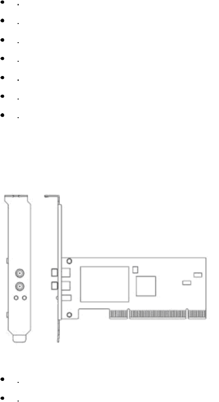
2. Designing Your PCI Adapter
PCI Adapter supports up to 300Mbps connections. It is fully compliant with the specifications defined
in 802.11n standard.
The status LED indicators of PCI Card are described in the following.
Lnk/Act ON (Green): Indicates a valid connection.
Lnk/Act Flashing: Indicates the Adapter is transmitting or receiving data.
4
3. Installation
3.1 Install Your PCI Adapter
Open your PC case and locate an available PCI on the motherboard.
Slide PCI Adapter into the PCI slot. Make sure that all of its pins are touching the slot's contacts.
You may have to apply a bit of pressure to slide PCI Adapter all the way in. after it is firmly in place,
secure its fastening tab to your PC's chassis with a mounting screw. Then close your PC.
Attach the external antennas to PCI Adapter's antenna port.
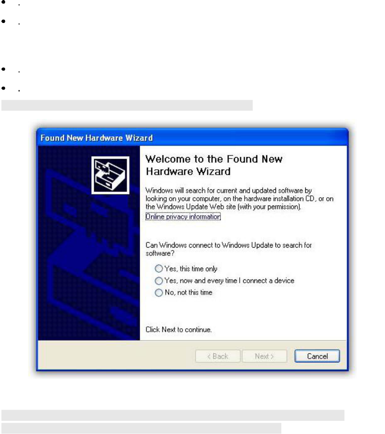
Power on the PC.
Note: Select Cancel when "Found New Hardware window appears.
3.2 Install Driver and Utility
NOTE: Snap-shot screens of the following installation procedure are based on Windows XP.
Installation procedures will be similar for other windows operating systems.
1. Insert Installation CD to your CD-ROM drive. And click Driver Installation. The wizard will install
all necessary files to your computer automatically.
2. Click Next to accept the Agreement. Or click Cancel to cancel the installation.
5
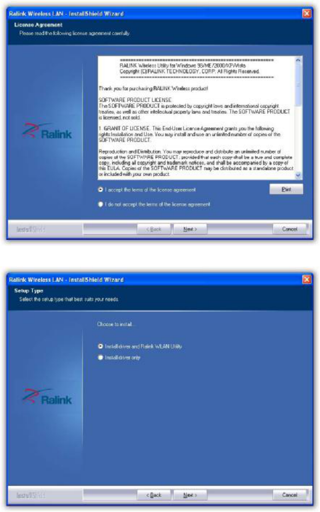
3. Click Next.
6
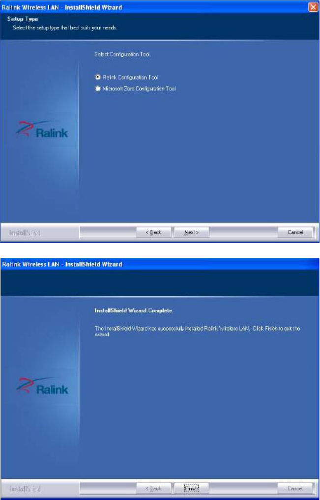
4. Select Ralink Configuration Tool or Microsoft Zero Configuration Tool then click Next.
a. It#s recommended to select Ralink Configuration Tool, which provides fully access to all function of
PCI Adapter.
b. If you prefer to use the wireless configuration tool provided by Windows XP or Vista, please select
Microsoft Zero Configuration Tool.
5. Click Finish to complete the software installation.
7
4. Utility Configure
4.1 WZC
4.1.1 Ralink Wireless Utility (RaUI) or Windows Zero Configuration (WZC)
Windows XP includes a wireless configuration utility named "Windows Zero configuration" (WZC)
which provides basic configuration functions to the Ralink Wireless NIC. Ralink's utility (RaUI)
additionally provides WPA functionality. To make it easier for the user to select the correct utility. RaUI
will let users make a selection when it first runs after windows XP boots.
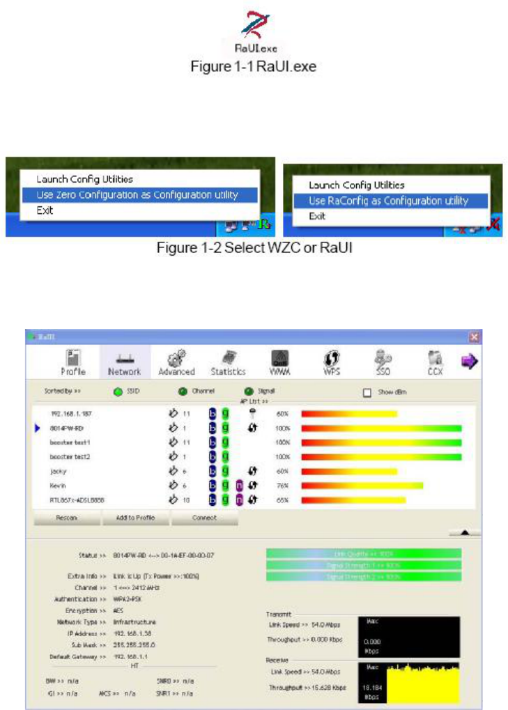
Double-clicking the icon will bring up the selection window and allow the user make a selection.
RaUI can co-exist with WZC. When coexisting with WZC, RaUI only provides monitoring functions,
such as surveying the link status, network status, statistic counters, advanced feature status, WMM
status and WPS status. It won't interfere with WZC's configuration or profile functions. It is shown as
Figure 1-2.
If "Use RaConfig as Configuration utility" is selected, please jump to Section 2 on running RaUI.
If "Use Zero Configuration as Configuration utility" is selected, please continue.
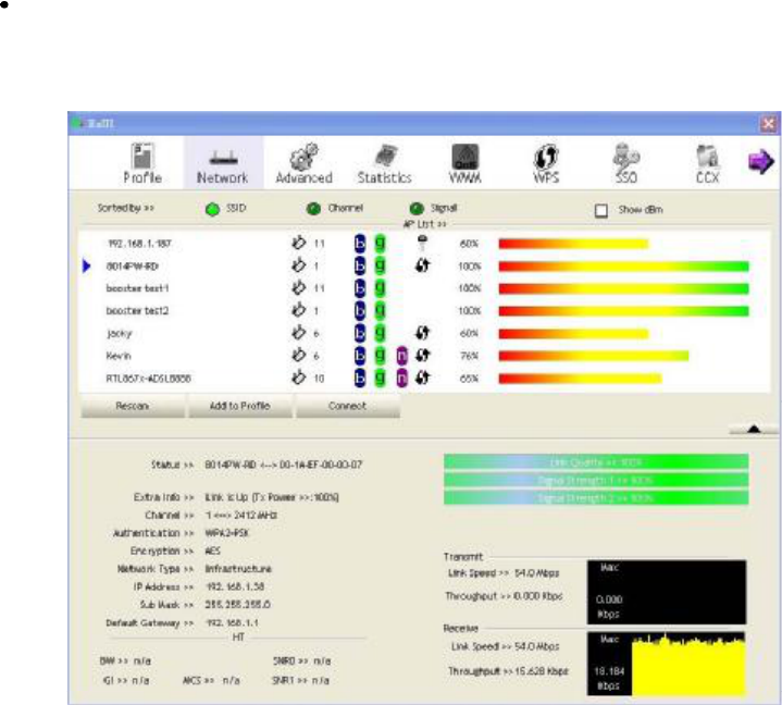
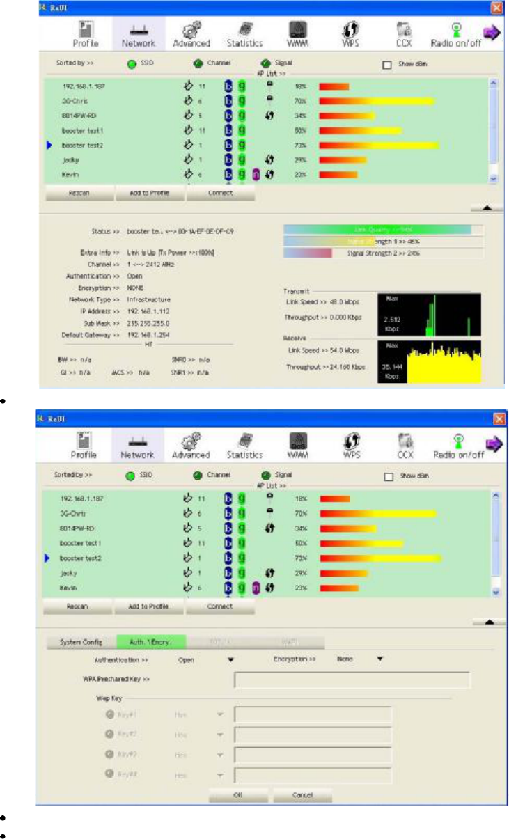
We will explain the difference between RaUI and WZC. Figure 1-3 shows the RaUI status when WZC
is activated as the main control utility.
Figure 1-3 RaUI status with WZC active
8
When activating WZC, there are several differences with the RaUI status, compared to the RaUI status
without WZC running.
The profile button will be gray. Profile functionality is removed since the NIC is controlled by
WZC.
The Connect and Add to Profile function will be gray. Profile functionality is removed since the
NIC is controlled by WZC.
Please read through this document for full details on the other functions provided byRaUI.
4.1.2 Use WZC to configure wireless NIC
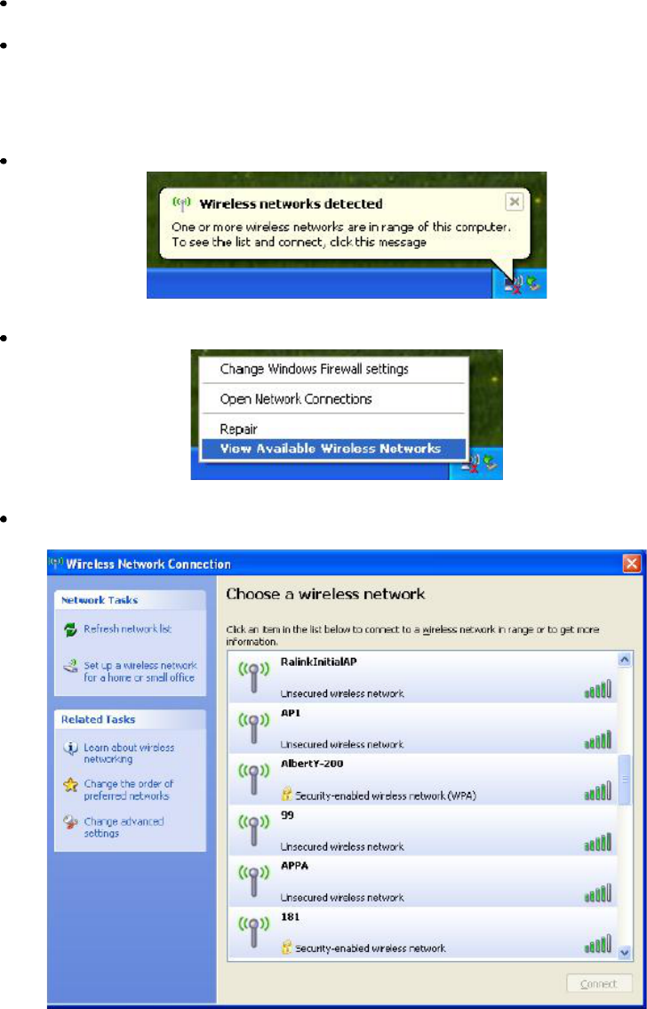
If there is no connection or it is lost, the status prompt will pop up, as shown in Figure 1-4.
Figure 1-4 status prompt for no connection
Right-click the network connection icon in taskbar.
Figure 1-5 Select WZC main status
Select "View Available Wireless Networks" and the "Wireless Network Connection" dialog box will
pop up, as shown in Figure 1-6.
Figure 1-6 Wireless Network Connection
9
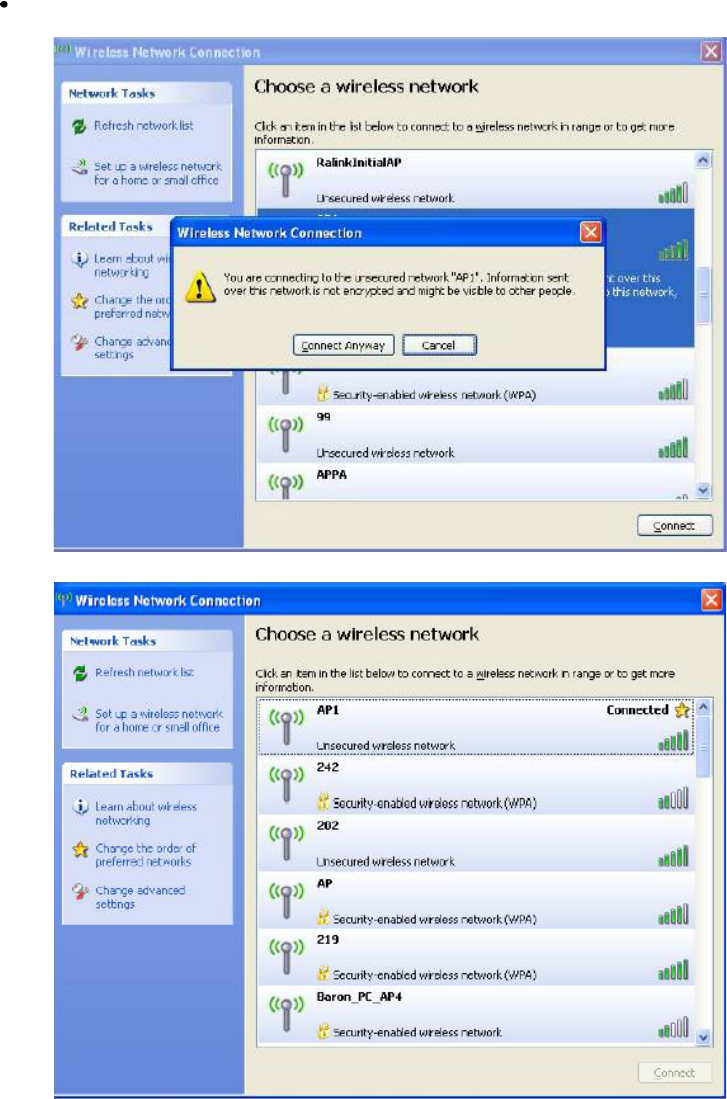
Select the intended access point and click "Connect". Then click "Connect Anyway" as shown as
Figure 1-7.
Figure 1-7 Select intended AP: AP1, then click "Connect"
Figure 1-8 Connect to AP: AP1 successfully
10
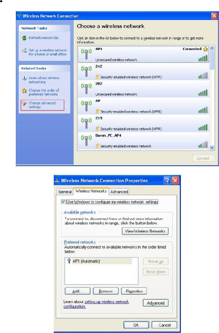
If you want to modify information about the AP, click "Change advanced settings "as shown in
Figure 1-9. Then select the "Wireless Networks" tab shown as Figure1-10.
Figure 1-9 Click "Change advanced settings"
Figure 1-10 choose the "Wireless Networks" tab
11
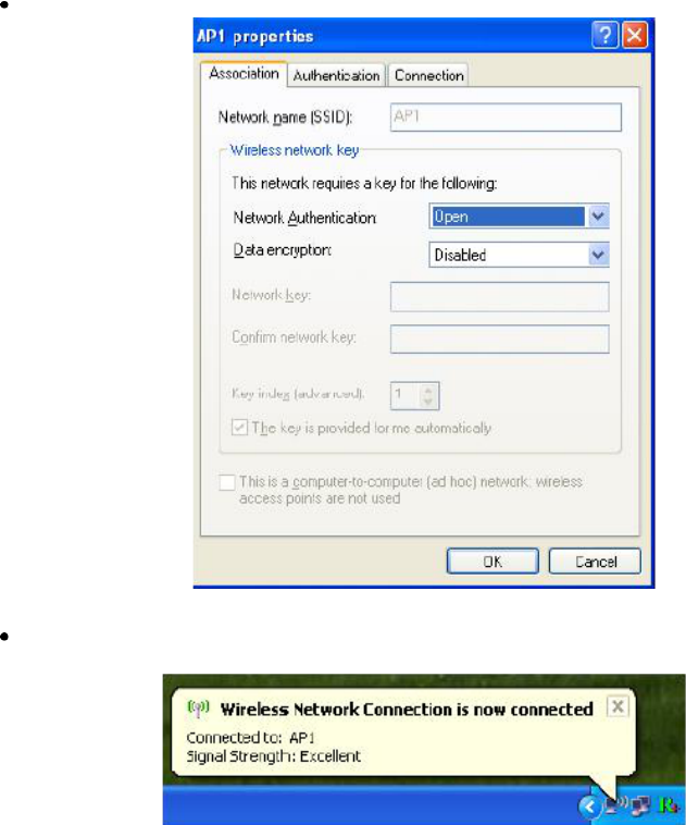
Click "Properties" as shown in Figure 1-11. Then click "OK" button.
Figure 1-11 AP's properties
After filling in the appropriate value, click "OK." The pop-up will indicate the status as shown in
Figure 1-12.
Figure 1-12 Network connection status
12
Clicking the Ralink icon will bring up the RaUI main window. Users can find the surrounding APs
in the list. The currently connected AP will be shown with a blue icon beside it, as shown in Figure
1-13. Users may use the advanced tab to configure more advanced features provided by Ralink's
wireless NIC. For details on configuring the advanced features, please check the Advance setting
section.
Figure 1-13 Show connection status by using WZC to initiate the connection
4.2 RaUI
4.2.1 Start
4.2.1.1 Start RaUI
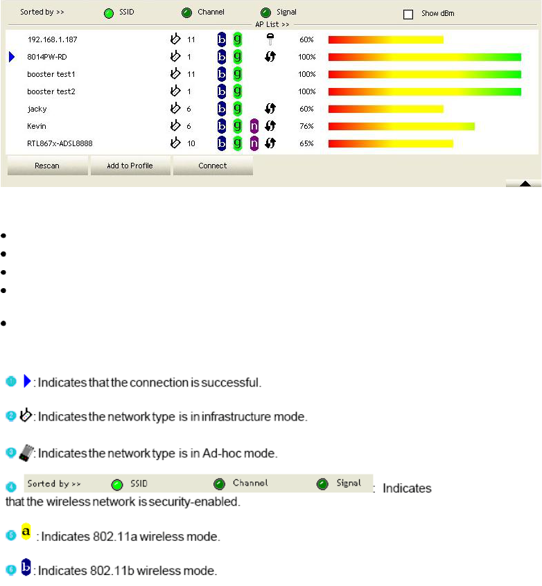
When starting RaUI, the system will connect to the AP with best signal strength without setting a
profile or matching a profile setting. When starting RaUI, it will issue a scan command to a wireless
NIC. After two seconds, the AP list will be updated with the results of a BSS list scan. The AP list
includes most used fields, such as SSID, network type, channel used, wireless mode, security status and
the signal percentage. The arrow icon indicates the connected BSS or IBSS network. The dialog box is
shown in Figure 2-1.
13
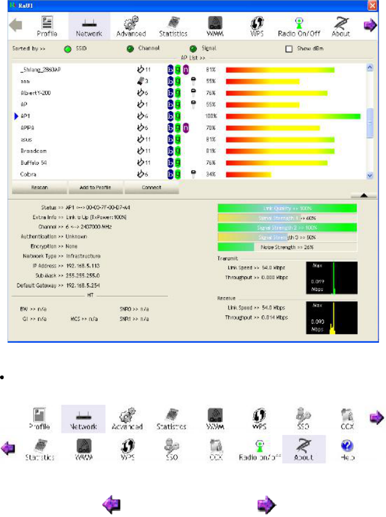
Figure 2-1-1 RaUI section introduction
There are three sections to the RaUI dialog box. These sections are briefly described as follow.
Button Section: Include buttons for selecting the Profile page, Network page, Advanced page,
Statistics page, WMM page, WPS page, SSO page, CCX page, and about button, Radio On/Off
button and Help.
Figure 2-1-2 Button section
Figure 2-1-3 Move to the left Figure 2-1-4 Move to the right
14
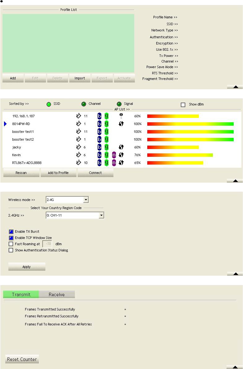
Function Section: Appears to present information and options related to the button.
Figure 2-1-5 Profile page
Figure 2-1-6 Network page
Figure 2-1-7 Advance page
Figure 2-1-8 Statistics page
15
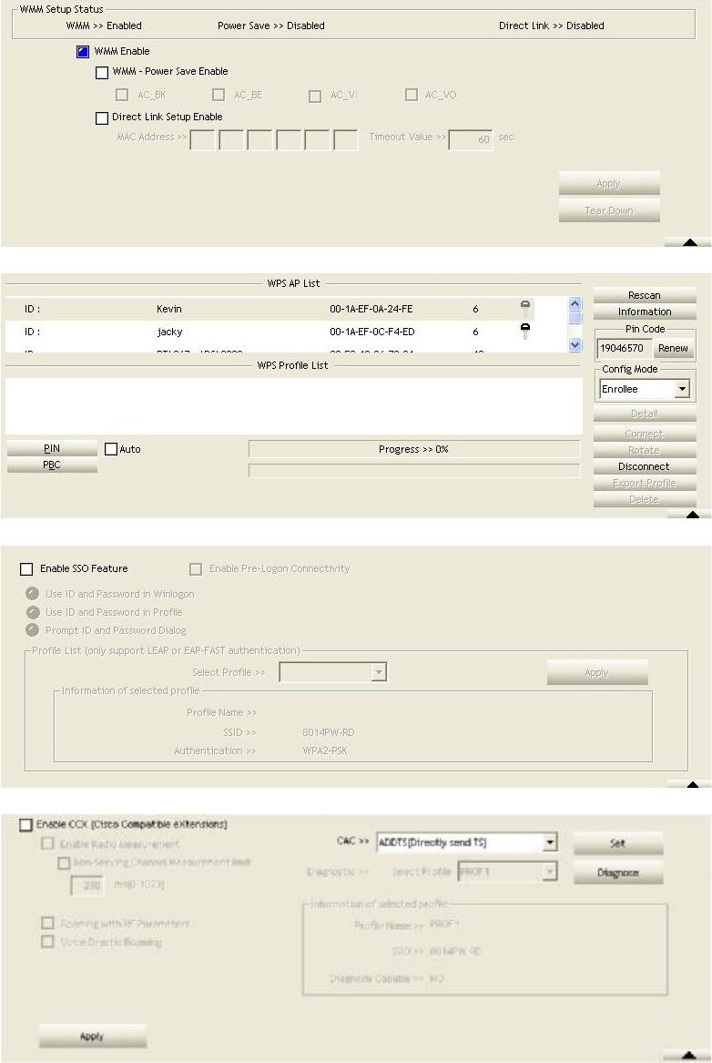
Figure 2-1-9 WMM page
Figure 2-1-10 WPS page
Figure 2-1-11 SSO page
Figure 2-1-12 CCX page
16
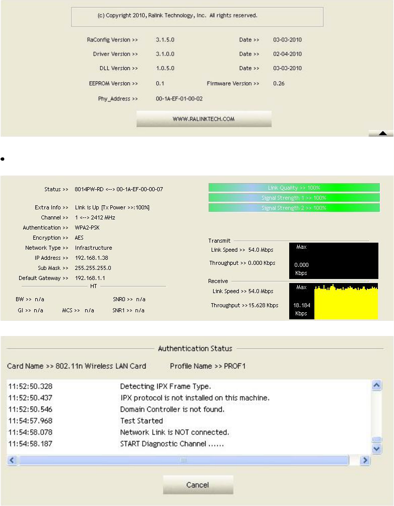
Figure 2-1-13 About page
Status Section: This section includes information about the link status,authentication status, AP's
information and configuration, and retrying the connection when authentication is failed.
Figure 2-1-14 Link Status
Figure 2-1-15 Authentication Status
17
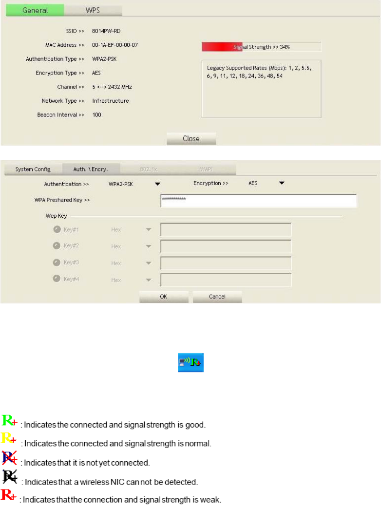
Figure 2-1-16 AP#s Information
Figure 2-1-17 Configuration
When starting RaUI, a small Ralink icon appears in the notifications area of the taskbar, as shown in
Figure 2-1-15. You can double click it to maximize the dialog box if you selected to close it earlier. You
may also use the mouse's right button toclose RaUI utility.
Figure 2-1-18 Ralink icon in system tray
Additionally, the small icon will change color to reflect current wireless network connection status. The
status is shown as follows:
4.2.2 Profile
4.2.2.1Profile
The Profile List keeps a record of your favorite wireless settings at home, office, and other public
hot-spots. You can save multiple profiles, and activate the correct one at your preference. Figure 2-2-1
shows the basic profile section.
18
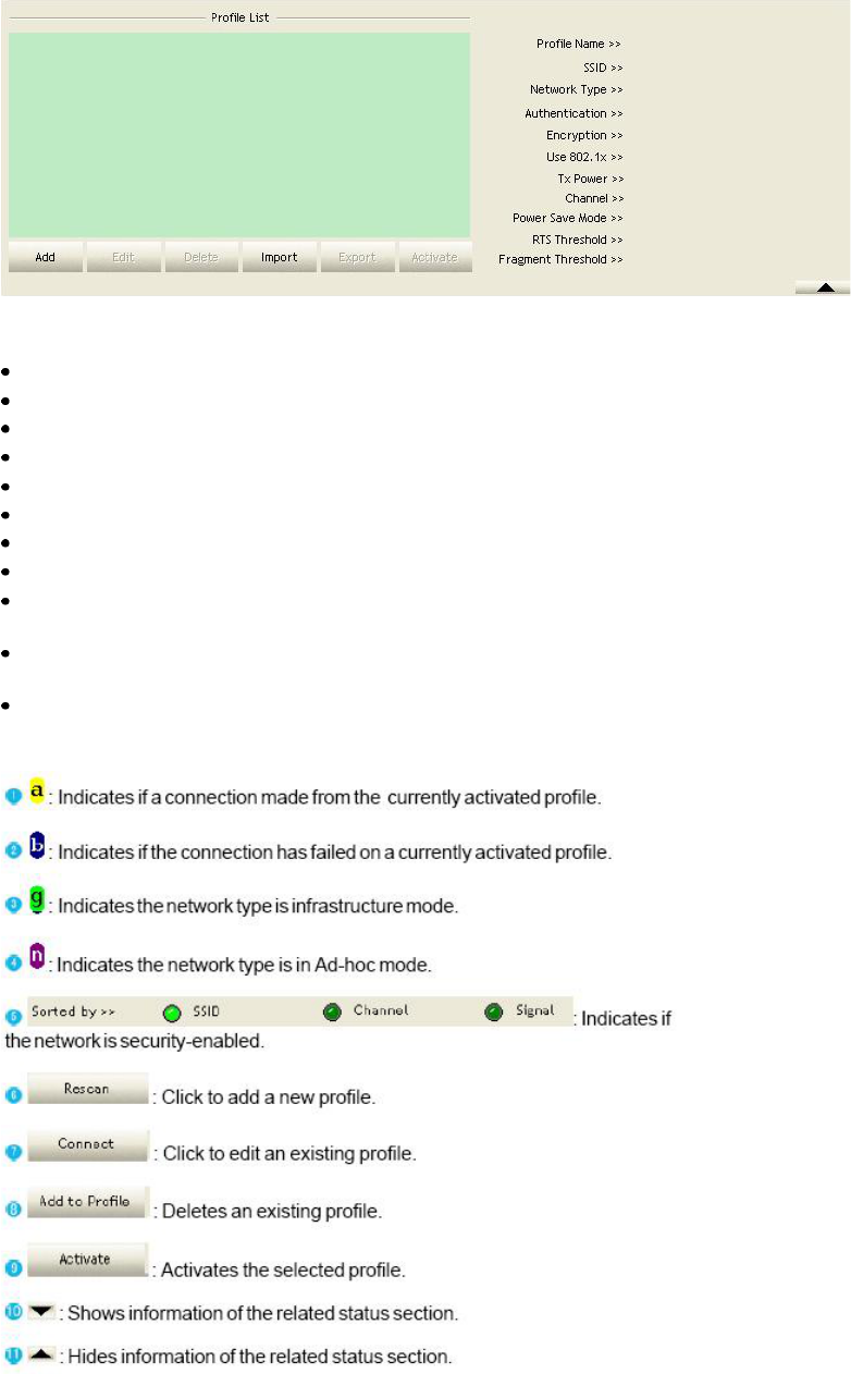
Figure 2-2-1 Profile function
Definition of each field:
Profile Name: Name of profile, preset to PROF* (* indicate 1, 2, 3...).
SSID: The access point or Ad-hoc name.
Network Type: Indicates the networks type, including infrastructure and Ad-Hoc.
Authentication: Indicates the authentication mode used.
Encryption: Indicates the encryption Type used.
Use 802.1x: Shows if the 802.1x feature is used or not.
Cannel: Channel in use for Ad-Hoc mode.
Power Save Mode: Choose from CAM (Constantly Awake Mode) or Power Saving Mode.
Tx Power: Transmitting power, the amount of power used by a radio transceiver tosend the signal
out.
RTS Threshold: Users can adjust the RTS threshold number by sliding the bar orkeying in the value
directly.
Fragment Threshold: The user can adjust the Fragment threshold number by sliding the bar or key in
the value directly.
Icons and buttons:
19
4.2.2.2Add/Edit Profile
There are three methods to open the Profile Editor dialog box.
You can open it by clicking the "Add to Profile" button in the Site Survey tab.
You can open it by clicking the "Add" button in the Profile tab.
You can open it by clicking the "Edit" button on the Profile tab.
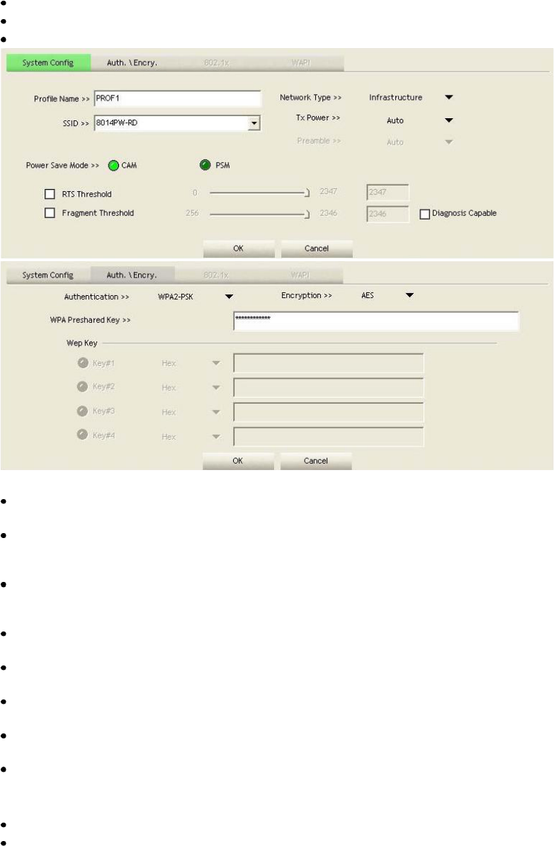
Figure 2-2-2 Configuration
Profile Name: The user can chose any name for this profile, or use the default name defined by
system.
SSID: The user can key in the intended SSID name or select one of the available APs from the
drop-down list. Power Save Mode: Choose CAM (Constantly Awake Mode) or Power Saving
Mode.
Network Type: There are two types, infrastructure and 802.11 Ad-hoc mode. Under Ad-hoc mode,
user can also choose the preamble type. The available preamble type includes auto and long. In
addition, the channel field will be available for setup in Ad-hoc mode.
RTS Threshold: User can adjust the RTS threshold number by sliding the bar, or key in the value
directly. The default value is 2347.
Fragment Threshold: User can adjust the Fragment threshold number by sliding the bar or key in the
value directly. The default value is 2346.
Channel: Only available for setting under Ad-hoc mode. Users can choose the channel frequency to
start their Ad-hoc network.
Authentication Type: There are 7 type of authentication modes supported by RaUI. They are open,
Shared, LEAP, WPA and WPA-PSK, WPA2 and WPA2-PSK.
Encryption Type: For open and shared authentication mode, the selection of available encryption
type are none and WEP. For WPA, WPA2, WPA-PSK andWPA2-PSK authentication mode,
both TKIP and AES encryption is available.
802.1x Setting: This is introduced in the topic of "Section 3-2 : 802.1x Setting".
WPA Pre-shared Key: This is the key shared between the AP and STA. For WPA-PSK and
WPA2-PSK authentication mode, this field must be filled with a key between 8 and 32 characters in
20
length.
WEP Key: Only valid when using WEP encryption algorithms. The key must be identical to the
AP's key. There are several formats to enter the keys.
1. Hexadecimal - 40bits: 10 Hex characters.
2. Hexadecimal - 128bits: 26Hex characters.
3. ASCII - 40bits: 5 ASCII characters.
4. ASCII - 128bits: 13 ASCII characters.
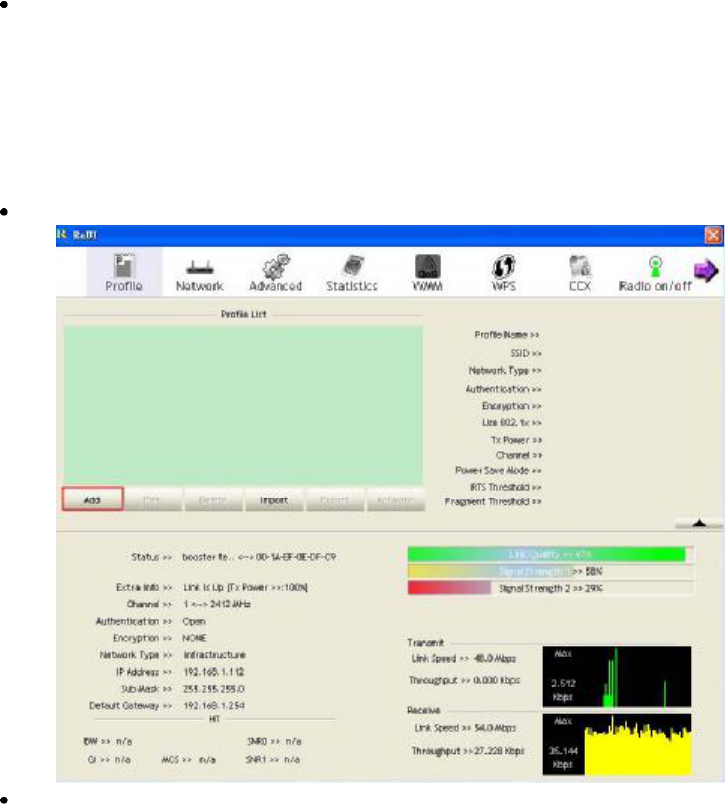
4.2.2.3Example to Add Profile in Profile
Click "Add" below the Profile List.
The "Add Profile" will appear.
21
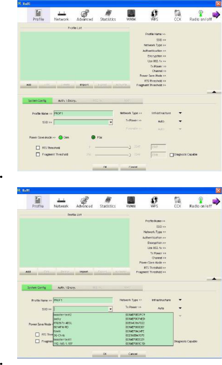
Specify a Profile Name. Select an AP from the SSID drop-down list. The AP list from the last
Network.
Now the profile which the user set appears in the profile list. Click "Activate".
22
4.2.3 Network
4.2.3.1Network
The system will display the information of local APs from the last scan result as part of the Network
section. The Listed information includes the SSID, BSSID, Signal, Channel, Encryption algorithm,
Authentication and Network type as shown in Figure 2-3-1-1.
Figure 2-3-1-1 Network function
Definition of each field:
SSID: Name of BSS or IBSS network.
Network Type: Network type in use, Infrastructure for BSS, Ad-Hoc for IBSS network.
Channel: Channel in use.
Wireless Mode: AP support wireless mode. It may support 802.11a, 802.11b, 802.11g or 802.11n
wireless mode.
Security-Enable: Indicates if the AP provides a security-enabled wireless network. Signal: Receive
signal strength of the specified network.
Icons and buttons:
23
Connected network:
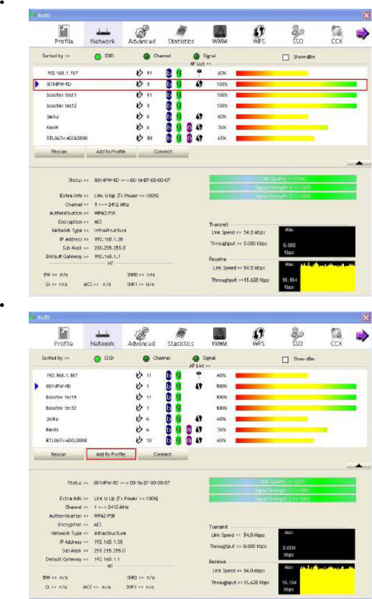
When RaUI first runs, it will select the best AP to connect to automatically.
If the user wants to use another AP, they can click "Connect" for the intended AP to make a
connection.
If the intended network uses encryption other than "Not Use," RaUI will bring up the security page
and let the user input the appropriate information to make the connection. Please refer to the
example on how to fill in the security information.
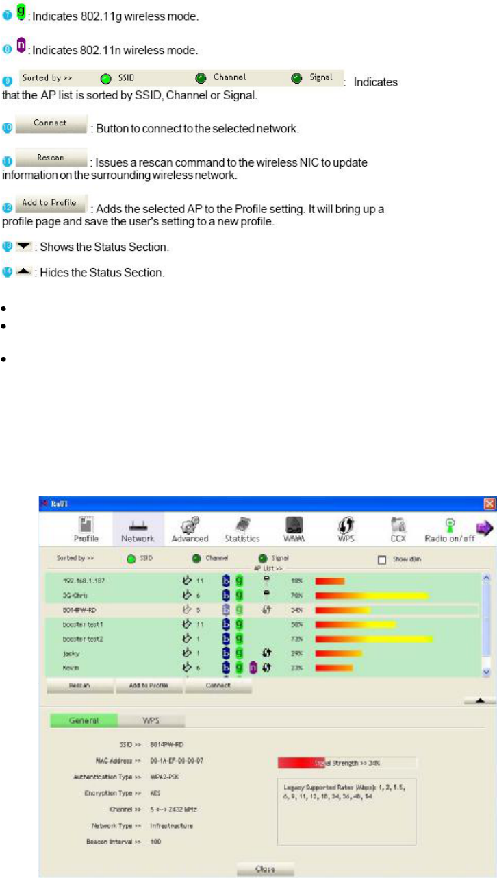
When you double click an AP, you can see detailed information about that AP.
The detailed AP information is divided into three parts. They are General, WPS, CCX information and
802.11n (The 802.11n button only exists for APs supporting N mode.) The introduction is as follows:
General information contains the AP#s SSID, MAC address, authentication type, encryption type,
channel, network type, beacon interval, signal strength and supported rates. It is shown in Figure
2-3-1-2.
24
4.2.3.2Example on Adding Profile in Network
Select the AP from the list on the Network tab
Click "Add to Profile"
25
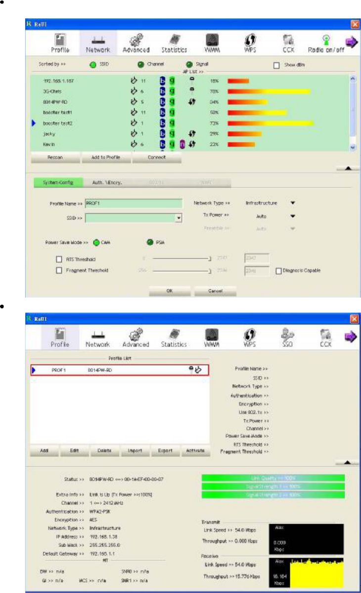
The System section will appear at the bottom of the Add Profile window. You can specify your own
profile name.
Next, you will see the new profile in the profile list. Click "Activate"
26
4.2.4 Advanced
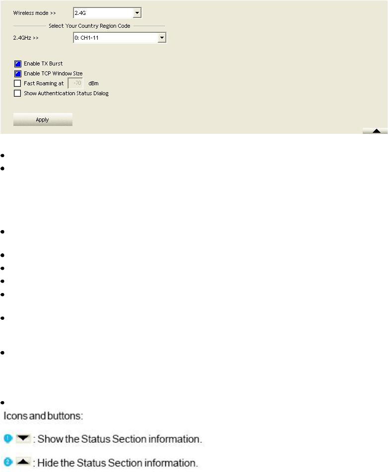
Figure 2-4 Advance function
Wireless mode: Select wireless mode. 2.4G, 5G and 2.4+5G are supported.
Wireless Protection: Users can choose from Auto, on, and off. (This is not supported by 802.11n
adapters.)
Auto: STA will dynamically change as AP announcement.
On: The frames are always sent with protection.
Off: The frames are always sent without protection.
TX Rate: Manually select the transfer rate. The default setting is auto. (802.11nwireless cards do not
allow the user to select the TX Rate.)
Enable TX Burst: Ralink's proprietary frame burst mode.
Enable TCP Window Size: Optimize the TCP window size to allow for greater throughput.
Fast Roaming at-: enables fast roaming, which is set by the transmit power.
Select Your Country Region Code: There are eight countries to choose from in the country channel
list. (11A List Box only shows for 5G adapter.)
Show Authentication Status Dialog: When you connect to an AP with authentication, choose
whether show the "Authentication Status Dialog" or not.The Authentication Status Dialog displays
the processes during 802.1x authentication.
Enable CCX (Cisco Compatible Extensions): Choose whether Cisco Compatible Extensions are
supported or not.
LEAP turn on CCKM.
Enable Radio Measurement: can measure the channel every 0~2000milliseconds.
Apply the above changes.
4.2.5 Statistics
The Statistics page displays detailed counter information based on 802.11 MIB counters. This page
translates that MIB counters into a format easier for the user to understand. Figure 2-5-1 shows the
detailed page layout.
27
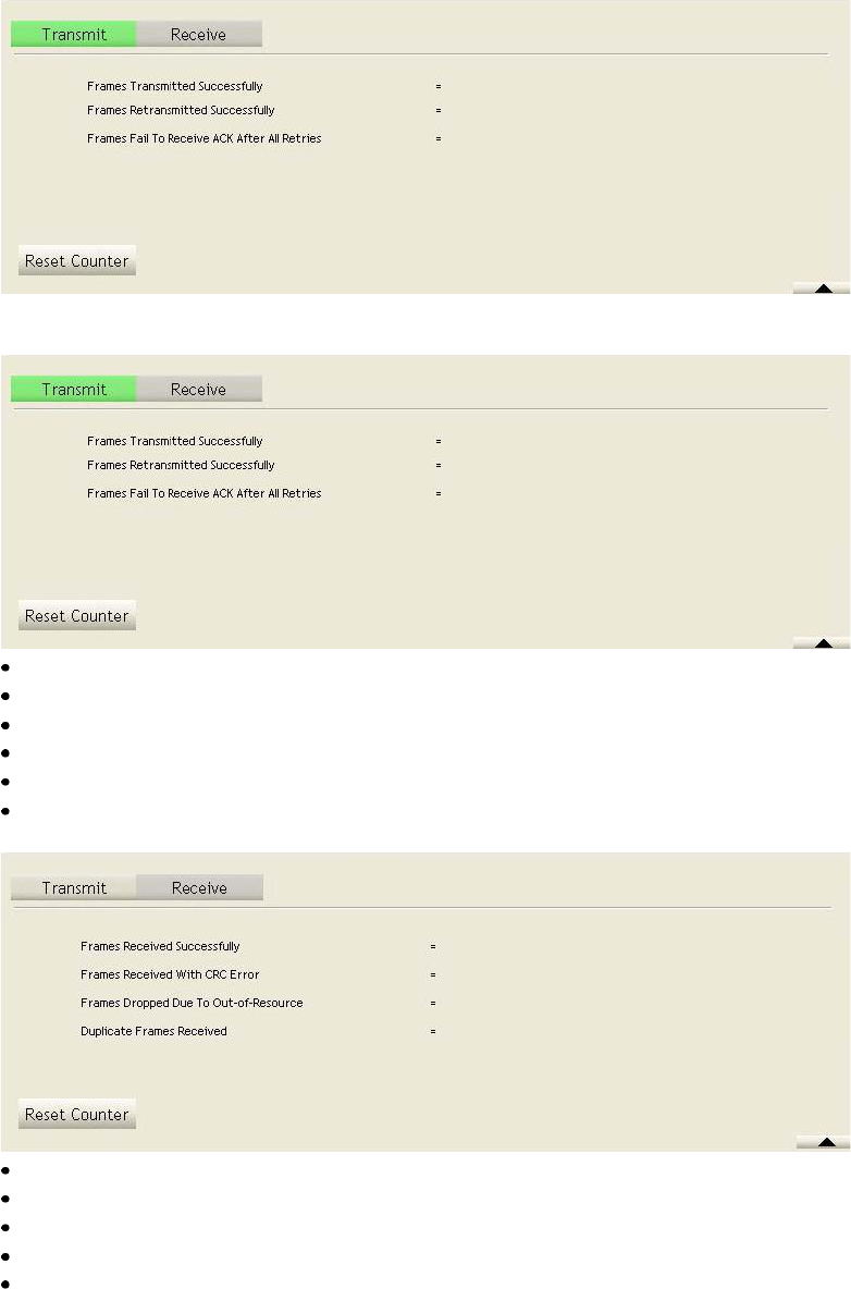
Figure 2-5-1 Statistics function
Transmit Statistics:
Frames Transmitted Successfully: Frames successfully sent.
Frames Fail To Receive ACK After All Retries: Frames failed transmit after hitting retry limit.
RTS Frames Successfully Receive CTS: Successfully receive CTS after sending RTS frame.
RTS Frames Fail To Receive CTS: Failed to receive CTS after sending RTS.
Frames Retransmitted Successfully: Successfully retransmitted frames numbers.
Reset counters to zero.
Receive Statistics:
Frames Received Successfully: The number of frames successfully received.
Frames Received With CRC Error: The number of frames received with a CRC error.
Frames Dropped Due to Out-of-Resource: The number of frames dropped due to a resource issue.
Duplicate Frames Received: The number of duplicate frames received.
Reset all the counters to zero.
28
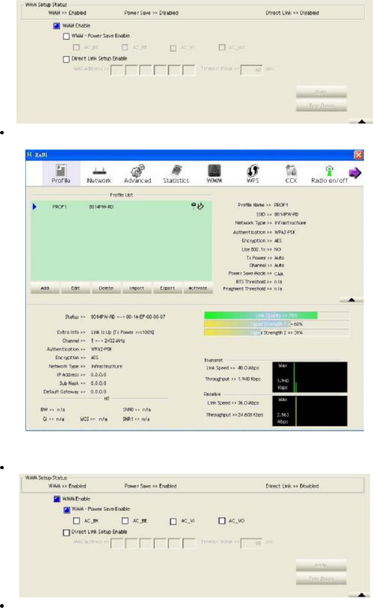
4.2.6 WMM
4.2.6.1WMM
Figure 2-6-1 shows WMM function of RaUI. It involves "WMM Enable", "WMM -Power Save
Enable" and DLS setup. The introduction indicates as follow:
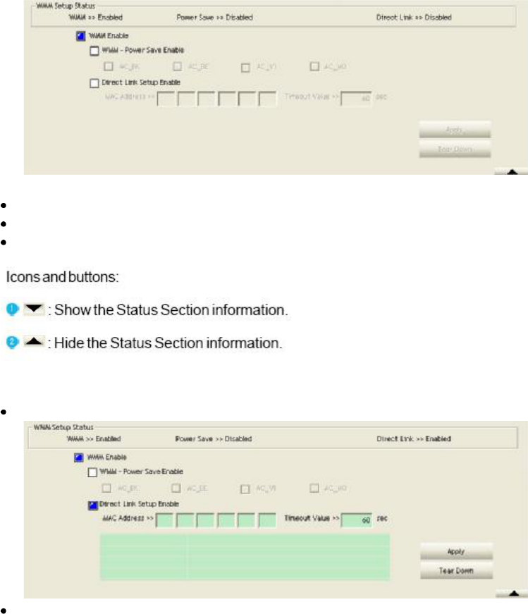
Figure 2-6-1 WMM function
WMM Enable: Enable Wi-Fi Multi-Media. The setting method follows Section 2-6-2.
WMM - Power save Enable: Enable WMM Power Save. The setting method follows Section 2-6-3.
Direct Link Setup Enable: Enable DLS (Direct Link Setup). The setting method follows Section
2-6-4.
4.2.6.2Example to Configure to Enable DLS (Direct Link Setup)
Click the "Direct Link Setup Enable" checkbox
Change to "Network" function. Add an AP that supports DLS features to the Profile. The result will
look like the Profile Page in the figure below.
29
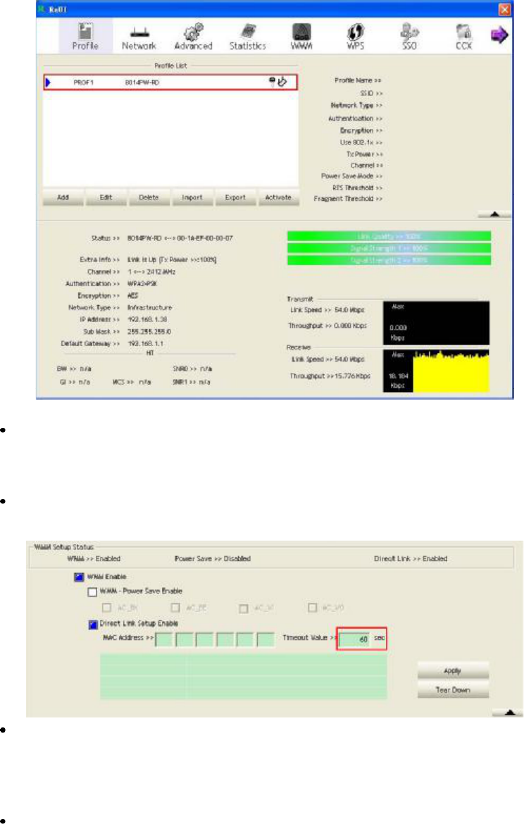
The DLS settings are explained as follows:
Fill in the blanks of Direct Link with MAC Address of STA. The STA must conform to these two
conditions:
1. Connect with an AP that supports DLS features.
2. Ensure that DLS is enabled.
The Timeout Value indicates the time in seconds before it disconnects automatically. The value is an
integer. The integer must be between 0~65535. A zero value specifies that it stays connected. The
default Timeout Value is 60seconds.
Click "Apply"
4.2.6.3Example to Configure to Enable Wi-Fi Multi-Media
If you want to use "WMM-Power Save" or "Direct Link" you must enable WMM. The setting method
of enabling WMM indicates as follows:
Click "WMM Enable".
30
Change to "Network" function. And add a AP that supports WMM features to a Profile. The result
will look like the below figure in Profile page.
4.2.6.4Example to Configure to Enable WMM-Power Save
Click "WMM-Power save Enable".
Please select which ACs you want to enable. The setting of enabling WMM-Power Save is
successfully.
31
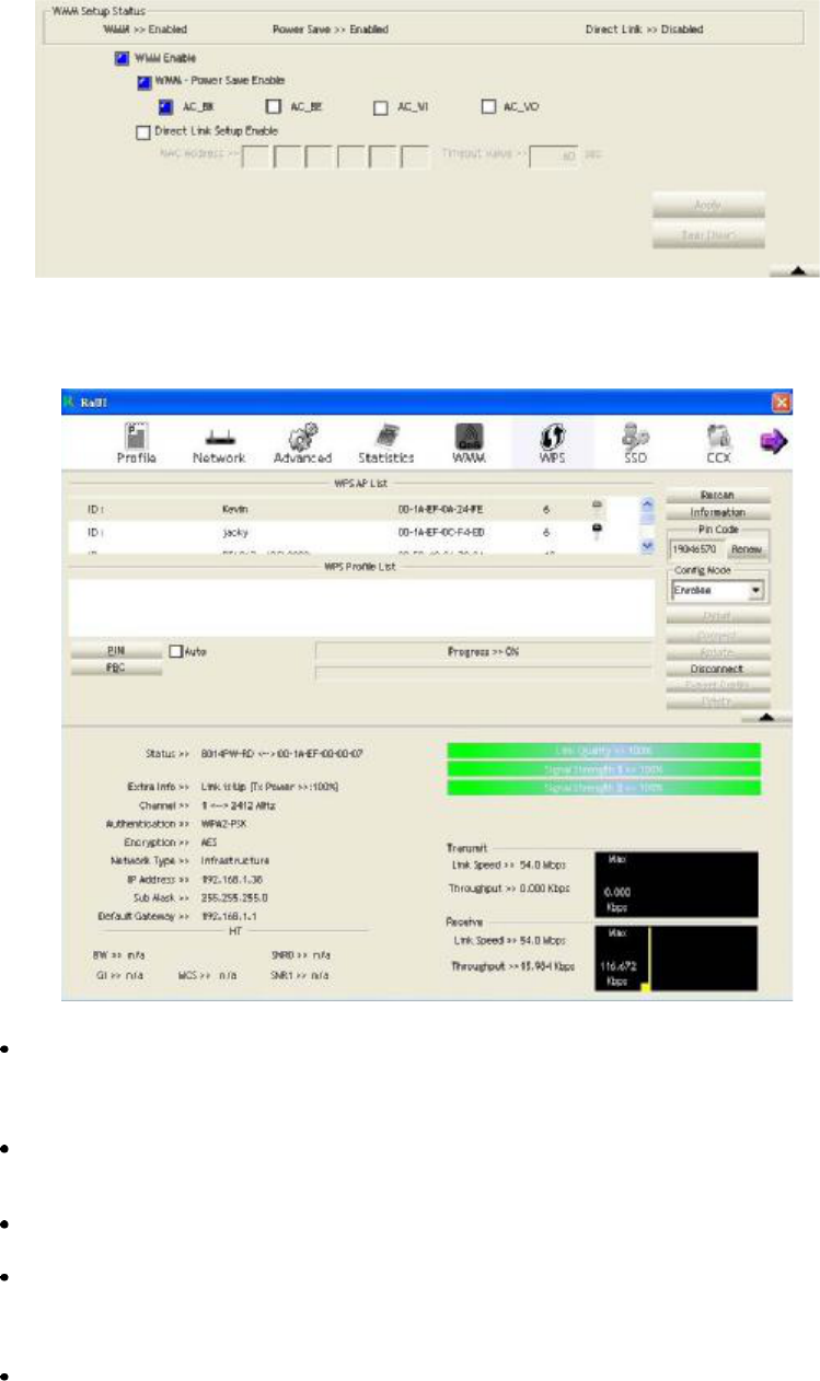
4.2.7 WPS
4.2.7.1WPS
Figure 2-7-1 WPS function
WPS Configuration: The primary goal of Wi-Fi Protected Setup (Wi-Fi Simple Configuration) is to
simplify the security setup and management of Wi-Fi networks. Ralink STA supports the
configuration and setup using a PIN configuration method or a PBC configuration method through
an internal or external Registrar.
WPS AP List: Displays the information of the surrounding APs with WPS IE from the last scan
result. The detailed information includes the SSID, BSSID, Channel, ID (Device Password ID),
Security-Enabled.
Rescan: Issues a rescan command to the wireless NIC to update information on the surrounding
wireless network.
Information: Displays the information about WPS IE on the selected network. The detailed list
includes the Authentication Type, Encryption Type, Config Methods, Device Password ID, Selected
Registrar, State, Version, AP Setup Locked, UUID-E and RF Bands. Further details are available
here: WPS Information on AP.
PIN Code: The user is required to enter an 8-digit PIN Code into Registrar. When an STA is the
Enrollee, you can click "Renew" to re-generate a new PIN Code.
32

Config Mode: The station serving as an Enrollee or an external Registrar.
Table of Credentials: Displays all credentials obtained by the Registrar. The detailed list includes
information about the SSID, MAC Address, Authentication and Encryption Type. If STA is the
Enrollee, the credentials are created immediately with each WPS success. If STA is the Registrar,
RaUI creates a new credential withWPA2-PSK/AES/64Hex-Key and doesn't change this until
switching to STA Registrar.
Control items for credentials.
1. Detail: Command to obtain Information about Security and the Key in the credential.
2. Connect: Command to connect to the selected network inside credentials. The active selected
credential is as like as the active selected Profile.
3. Rotate: Command to rotate to connect to the next network inside credentials.
4. Disconnect: Stops the WPS action and disconnects the active link. It then selects the most recent
profile on the Profile Page of RaUI. If there are no profiles, the driver will select any non-security AP.
5. Export Profile: Exports all credentials to a Profile.
6. Delete: Deletes an existing credential. And then selects the next credential. If there is not another
credential, the driver will select any non-security AP.
PIN: Start to add to Registrar using PIN configuration method. If STA Registrar, remember that
enter PIN Code read from your Enrollee before starting PIN.
PBC: Start to add to AP using PBC configuration method.
After the user clicks PIN or PBC, please do not rescan within two-minutes of the connection. If you
want to abort this setup within the interval, restart PIN/PBC or click "Disconnect" to stop WPS action.
WPS associate IE: Sends the association request with WPS IE during the WPS setup. It is optional
for STA.
WPS probe IE: Sends the probe request with WPS IE during WPS setup. It is optional for STA.
Progress Bar: Displays the rate of progress from Start to Connected.
Status Bar: Displays the current WPS Status.
Automatically select the AP: Starts to add to AP by using to select the AP automatically in PIN
method.
**There are examples in section 2-7-3(PIN Enrollee Setup), section 2-7-4(PBC Enrollee Setup) and
section 2-7-5(Registrar Configures and AP)**
33
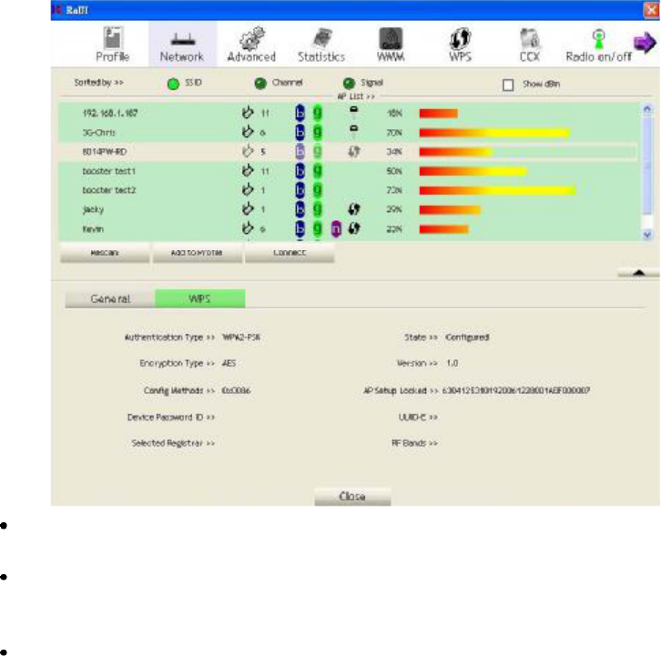
4.2.7.2WPS Information on AP
The WPS information (shown below) includes the authentication type, encryption
type, Config methods, device password ID, selected registrar, state, version, AP setup
locked, UUID-E and RF bands.
Authentication Type: There are three authentication modes supported by RaConfig.
They are open, Shared, WPA-PSK and WPA system.
Encryption Type: For open and shared authentication mode, the selection of
encryption type are None and WEP. For WPA, WPA2, WPA-PSK and WPA2-PSK
authentication mode, the encryption type supports both TKIP and AES.
Config Methods: Correspond to the methods the AP supports as an Enrollee for
adding external Registrars. (a bitwise OR of values)
Value Hardware Interface
0x0001 USBA (Flash Drive)
0x0002 Ethernet
0x0004 Label
0x0008 Display
0x0010 External NFC Token
0x0020 Integrated NFC Token
0x0040 NFC Interface
0x0080 Push Button
0x0100 Keypad
34
Device Password ID: Indicates the method or identifies the specific password that
the selected Registrar intends to use. The AP in PBC mode must indicate0x0004
within the two-minute Walk Time.
Value Description
0x0000 Default(PIN)
0x0001 User-specified
0x0002 Rekey
0x0003 Display
0x0004 Push Button (PBC)
0x0005 Registrar-specified
0x0006-0x000F Reserved
Selected Registrar: Indicates if the user has recently activated a Registrar to add an
Enrollee. The values are "TRUE" and "FALSE".
State: The current configuration state of the AP. The values are "Unconfigured" and
"Configured".
Version: The specified WPS version.
AP Setup Locked: Indicates if the AP has entered a locked setup state.
UUID-E: The universally unique identifier (UUID) element generated by the
Enrollee. The value is 16 bytes.
RF Bands: Indicates all of the RF bands available to the AP. A dual-band AP must
provide it. The values are "2.4GHz" and "5GHz".
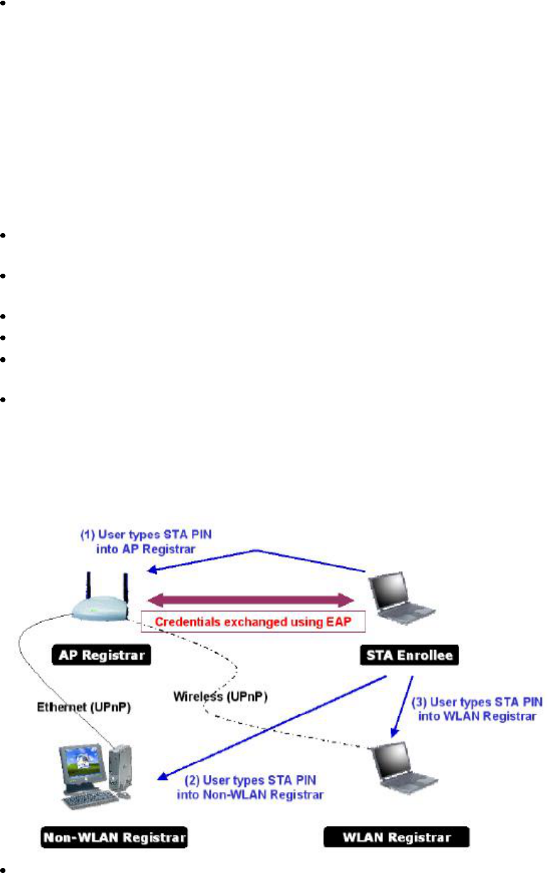
4.2.7.3Example to Add to Registrar Using PIN Method
The user obtains a device password (PIN Code) from the STA and enters the password into the
Registrar. Both the Enrollee and the Registrar use PIN Config method for the configuration setup. The
following image outlines the process.
Select "Enrollee" from the Config Mode drop-down list.
35
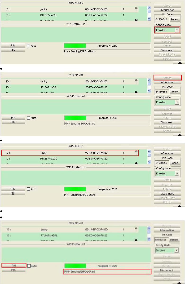
Click "Rescan" to update available WPS APs.
Select an AP (SSID/BSSID) that STA will join to.
Click "PIN" to enter the PIN
Enter the PIN Code of the STA into the Registrar when prompted by the Registrar.
The user can also click "Rotate" to rotate to the next credential usable credential.
36
Describe "WPS Status Bar" - "PIN - xxx" as follow:
Acceptable PIN Configurations:
Start PIN connection - SSID ~> Begin associating to WPS AP ~> Associated to WPS AP ~> Sending
EAPOL-Start ~> Sending EAP-Rsp (ID) ~> Receive EAP-Req(Start) ~> Sending M1 ~> Received M2
~> (Received M2D ~> Sending EAP-Rsp(ACK)) ~> Sending M3 ~> Received M4 ~> Sending M5 ~>
Received M6 ~>Sending M7 ~> Received M8 ~> Sending EAP-Rsp(Done) ~> Configured ~> WPS
status is disconnected ~> WPS status is connected successfully-SSID
WPS configuration doesn't complete after a two-minute connection:
WPS EAP process failed.
When errors occur within two minutes of connecting, the WPS status bar might report "WPS EAP
process failed".
Error messages might be:
1. Receive EAP with wrong NONCE.
2. Receive EAP without integrity.
3. Error PIN Code.
4. An inappropriate EAP-FAIL received.
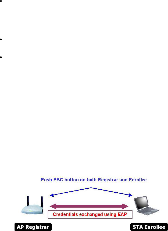
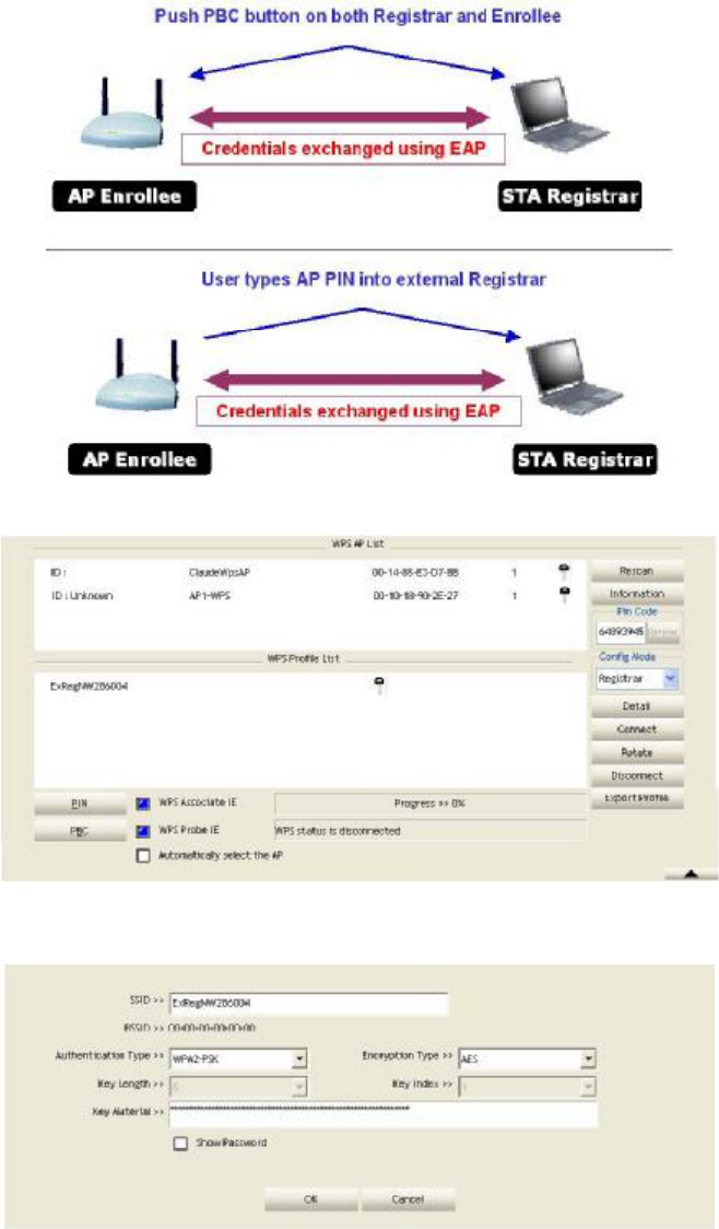
4.2.7.4Example to Add to Registrar Using PBC Method
The PBC method requires the user to press a PBC button on both the Enrollee and the Registrar within
a two-minute interval called the Walk Time. If there is only one Registrar in PBC mode, the PBC mode
selected is obtained from ID 0x0004, and is found after a complete scan. The Enrollee can then
immediately begin running the Registration Protocol.
If the Enrollee discovers more than one Registrar in PBC mode, it MUST abort its connection attempt
at this scan and continue searching until the two-minute timeout.
*Before you press PBC on STA and candidate AP. Make sure all APs aren't PBC mode or APs using
PBC mode have left their Walk Time.
1. Select "Enrollee from the Config Mode drop-down list.
37
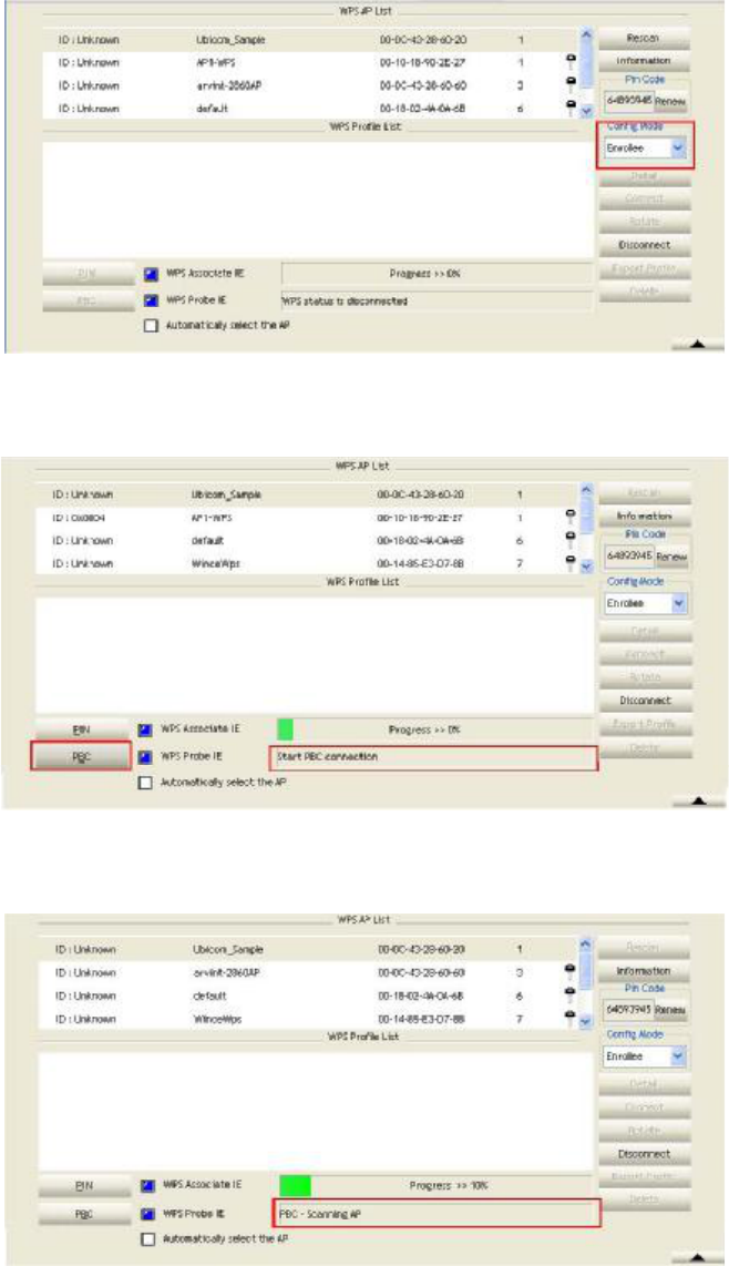
2. Click PBC to start the PBC connection.
3. Push the PBC on AP.
*Allow time for an exchange between Step 2 and Step 3.
4. The progress bar as shown in the figure below indicates that scanning progress.
5. When one AP is found, join it.
38
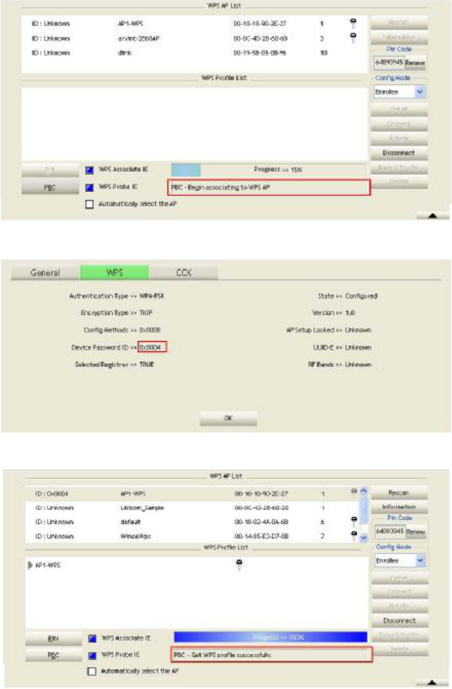
6. Check WPS Information on the available WPS APs
7. Configure and receive one or more credential(s).
8. Then connect successfully. The result will be displayed as it is in the figure below.
39
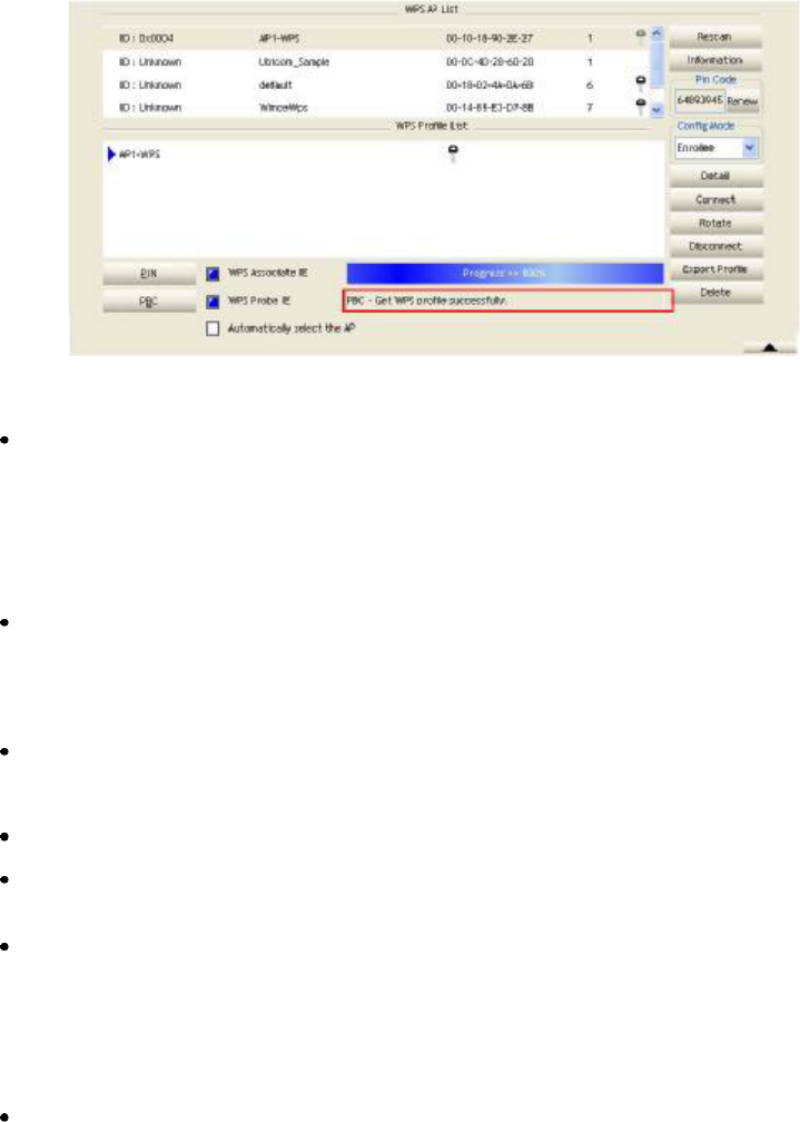
Describe "WPS Status Bar" -"PBC - xxx" as follow :
A successful PBC Configuration :
Start PBC connection ~> Scanning AP ~> Begin associating to WPS AP ~> Associated to WPS AP ~>
Sending EAPOL-Start ~> Sending EAP-Rsp (ID) ~> Receive EAP-Rsp (Start) ~> Sending M1 ~>
Received M2 ~> Sending M3 ~> Received M4 ~> Sending M5 ~> Received M6 ~> Sending M7 ~>
Received M8 ~> Sending EAP-Rsp (Done) ~> Configured ~> WPS status is disconnected ~> WPS
status is connected successfully-SSID
No PBC AP available :
Scanning AP ~> No PBC AP available ~> Scanning AP ~> No PBC AP available
~>...
Too Many PBC AP available :
Scanning AP ~> Too Many PBC AP available ~> Scanning AP ~> Too Many PBC AP available ~>...
WPS configuration doesn't complete after two-minute connection: WPS Eap process failed.
When Errors occur within two-minutes of establishing a connection, the WPS status bar might
report "WPS Eap process failed"
Error messages might be:
1. Receive EAP with wrong NONCE.
2. Receive EAP without integrity.
3. An inappropriate EAP-FAIL received.
Describe "Multiple PBC session overlaps" as follow:
Dual bands:
AP1 is a G-Band AP using PBC mode. (ID = 0x0004)
AP2 is a A-Band AP using PBC mode. (ID = 0x0004)
They have the same UUID-E.
STA would regard these two APs as a dual-radio AP and select one band to connect.
Different UUID-E:
AP1 is a G-Band AP using PBC mode. (ID = 0x0004)
40
AP2 is a G-Band AP using PBC mode. (ID = 0x0004)
They have the different UUID-E. STA would regard these two APs as two different APs and wait until
only one PBC AP is available.
4.2.7.5Example to Configure a Network/AP Using PIN or PBC Method
Select Registrar from the Config Mode drop-down list.
Enter the details of the credential and change configurations (SSID, Authentication, Encryption and
Key) manually if needed.
If the PIN configuration is setup, enter the PIN sent from the Enrollee.
41
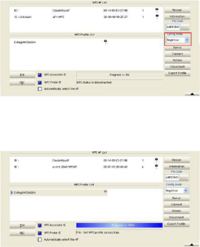
Start PIN or PBC. The following procedures are as similar as section 2-7-3 (PIN Enrollee Setup) or
section 2-7-4(PBC Enrollee Setup)
If your AP Enrollee has been configured before the WPS process, the credential you set in advance will
be updated to the AP itself. Otherwise, after a successful registration, the AP Enrollee will be
re-configured with the new parameters, and the STA Registrar will connect to the AP Enrollee with
these new parameters.
Describe "WPS Status Bar" - "PIN - xxx" as follow:
A successful PIN Configuration:
Start PIN connection - SSID ~> Begin associating to WPS AP ~> Associated to WPS AP ~> Sending
EAPOL-Start ~> Sending EAP-Rsp (ID) ~> Receive M1 ~> Sending M2 ~> Receive M3 ~> Sending
M4 ~> Receive M5 ~> Sending M6 ~> Receive M7 ~> Sending M8 ~> Receive EAP Rsp (Done) ~>
Sending EAP Rsp (ACK) ~> Configured ~> WPS status is disconnected ~> WPS status is connected
successfully-SSID
Describe "WPS Status Bar" -"PBC - xxx" as follow:
A successful PBC Configuration:
Start PBC connection ~> Scanning AP ~> Begin associating to WPS AP ~> Associated to WPS AP ~>
Sending EAPOL-Start ~> Sending EAP-Rsp (ID) ~> Receive M1 ~> Sending M2 ~> Receive M3 ~>
Sending M4 ~> Receive M5 ~> Sending M6 ~> Receive M7 ~> Sending M8 ~> Receive EAP Rsp
(Done) ~> Sending EAP Rsp (ACK) ~> Configured ~> WPS status is disconnected ~> WPS status is
connected successfully-SSID
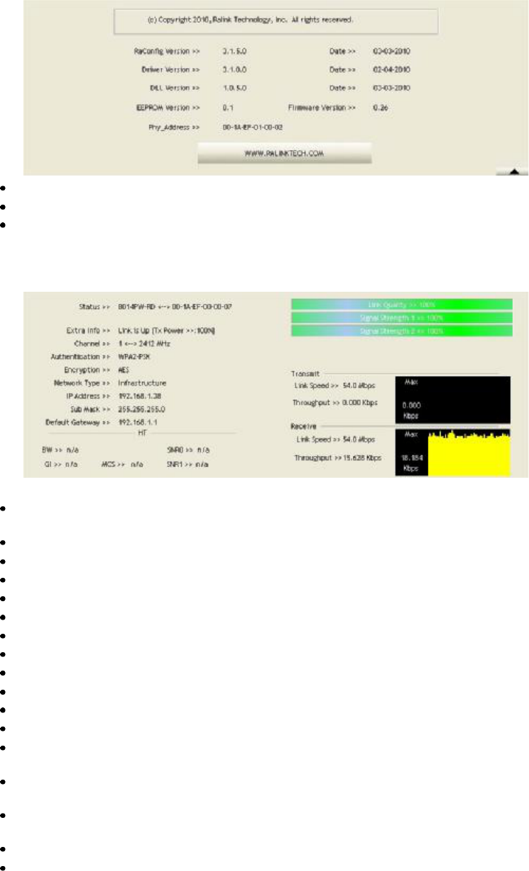
4.2.8 About
Click "About" displays the wireless card and driver version information as shown in Figure 2-8.
42
Connect to Ralink's website: Ralink Technology, Corp.
Display Configuration Utility, Driver, and EEPROM version information.
Display Wireless NIC MAC address.
4.2.9 Link Status
The link status page displays detailed information about the current connection as shown in Figure 2-9.
Figure 2-9 Link Status function
Status: Current connection status. If no connection, if will show Disconnected. Otherwise, the SSID
and BSSID will show here.
Extra Info: Display link status in use.
Channel: Display current channel in use.
Authentication: Authentication mode in use.
Encryption: Encryption type in use.
Network Type: Network type in use.
IP Address: IP address about current connection.
Sub Mask: Sub mask about current connection.
Default Gateway: Default gateway about current connection.
Link Speed: Show current transmit rate and receive rate.
Throughout: Display transmits and receive throughput in unit of Mbps.
Link Quality: Display connection quality based on signal strength and TX/RX packet error rate.
Signal Strength 1: Receive signal strength 1, user can choose to display as percentage or dBm
format.
Signal Strength 2: Receive signal strength 2, user can choose to display as percentage or dBm
format.
Signal Strength 3: Receive signal strength 3, user can choose to display as percentage or dBm
format.
Noise Strength: Display noise signal strength.
HT: Display current HT status in use, containing BW, GI, MCS, SNR0, and SNR1value. (Show the
information only for 802.11n wireless card.)
43
4.3 Security
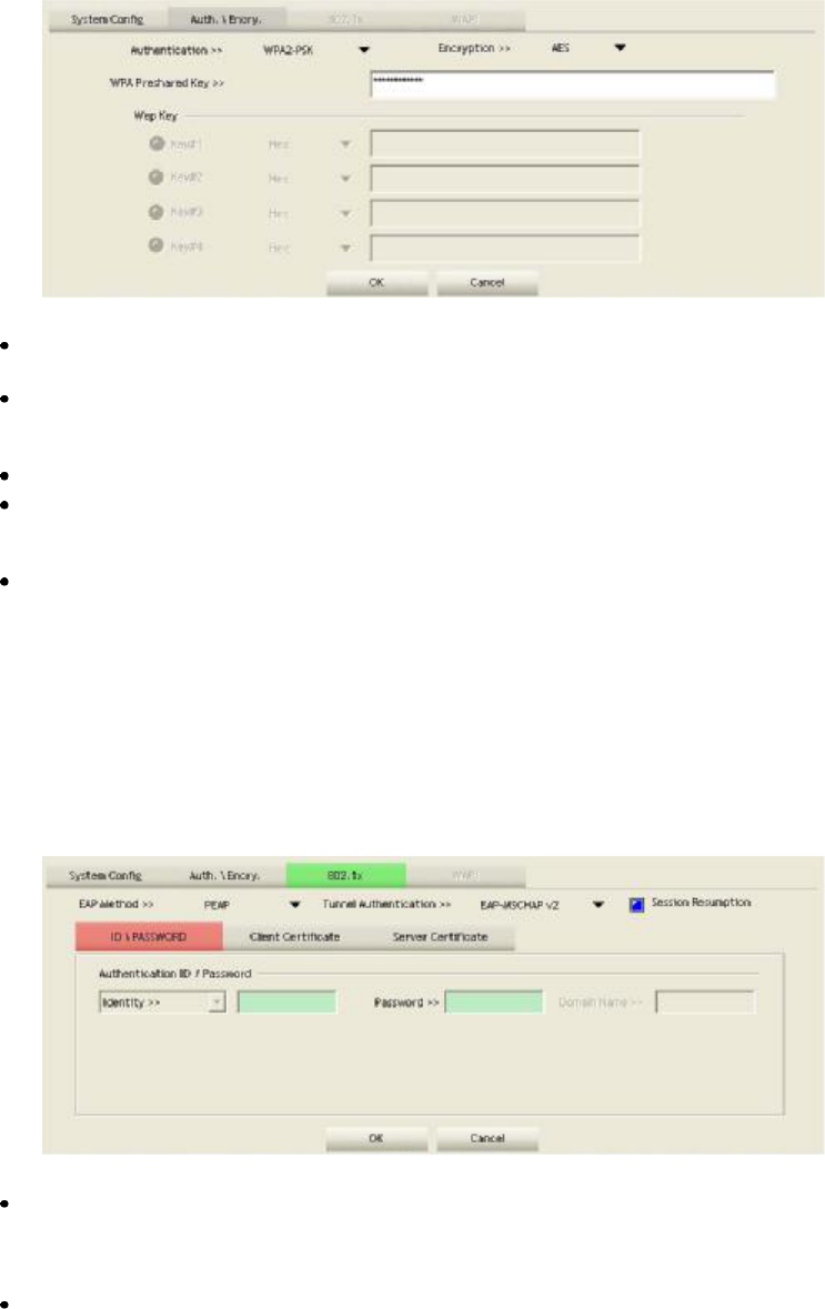
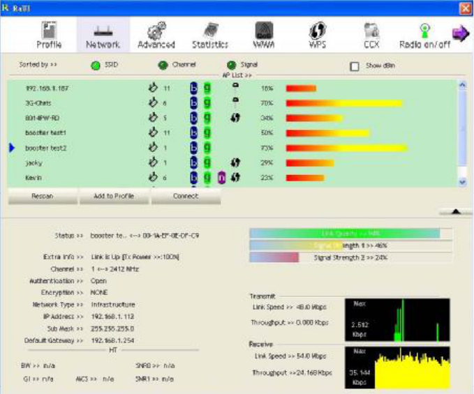
4.3.1 Auth.\Encry. Setting-WEP/TKIP/AES
Figure 3-1 Auth.\Encry. Settings
Authentication Type: There are 7 authentication modes supported by RaUI. They are open, Shared,
LEAP, WPA and WPA-PSK, WPA2 and WPA2-PSK.
Encryption Type: For open and shared authentication mode, the available encryption types are None
and WEP. For WPA, WPA2, WPA-PSK and WPA2-PSKauthentication mode, the encryption type
supports both TKIP and AES.
8021X: This is introduced in the topic of Section 3-2.
WPA Pre-shared Key: This is the shared key between the AP and STA. If operating in WPA-PSK
and WPA2-PSK authentication mode, this field must be filled with a key between 8 and 32
characters in length.
WEP Key: Only valid when using WEP encryption algorithm. The key must match the AP's key.
There are several formats to enter the keys.
Hexadecimal - 40bits: 10 Hex characters.
Hexadecimal - 128bits: 32Hex characters.
ASCII - 40bits: 5 ASCII characters.
ASCII - 128bits: 13 ASCII characters.
4.3.2 802.1x Setting
802.1x is used for authentication of the "WPA" and "WPA2" certificate by the server.
Authentication type:
PEAP: Protect Extensible Authentication Protocol. PEAP transport securely authenticates data by
using tunneling between PEAP clients and an authentication server. PEAP can authenticate wireless
LAN clients using only server-side certificates, thus simplifying the implementation and
administration of a secure wireless LAN.
TLS/Smart Card: Transport Layer Security. Provides for certificate-based and mutual authentication
of the client and the network. It relies on client-side and server-side certificates to perform
44
authentication and can be used to dynamically generate user-based and session-based WEP keys to
secure subsequent communications between the WLAN client and the access point.
TTLS: Tunneled Transport Layer Security. This security method provides for certificate-based,
mutual authentication of the client and network through an encrypted channel. Unlike EAP-TLS,
EAP-TTLS requires only server-side certificates.
EAP-FAST: Flexible Authentication via Secure Tunneling. It was developed by Cisco. Instead of
using a certificate, mutual authentication is achieved by means of a PAC (Protected Access
Credential) which can be managed dynamically by the authentication server. The PAC can be
supplied (distributed one time) to the client either manually or automatically. Manually, it is
delivered to the client via disk or a secured network distribution method. Automatically, it is
supplied as an in-band, over the air, distribution. For tunnel authentication, only support "Generic
Token Card" authentication.
LEAP: Light Extensible Authentication Protocol is an EAP authentication type used primarily by
Cisco Aironet WLANs. It encrypts data transmissions using dynamically generated WEP keys, and
supports mutual authentication.
MD5-Challenge: Message Digest Challenge. Challenge is an EAP authentication type that provides
base-level EAP support. It provides for only one-way authentication - there is no mutual
authentication of wireless client and the network.
Session Resumption: The user can choose "Disable" and "Enable".
Tunnel Authentication:
Protocol: Tunnel protocol, List information include "EAP-MSCHAP v2", "EAP-TLS/Smart card",
"Generic Token Card", "CHAP", "MS-CHAP", "MS-CHAP-V2","PAP" and "EAP-MD5".
Tunnel Identity: Identity for tunnel.
Tunnel Password: Password for tunnel.
ID \ PASSWORD
Authentication ID/Password: The identity, password and domain name for server. Only
"EAP-FAST" and "LEAP" authentication can key in domain name. Domain names can be keyed in
the blank space.
Tunnel ID/Password: Identity and Password for the server.
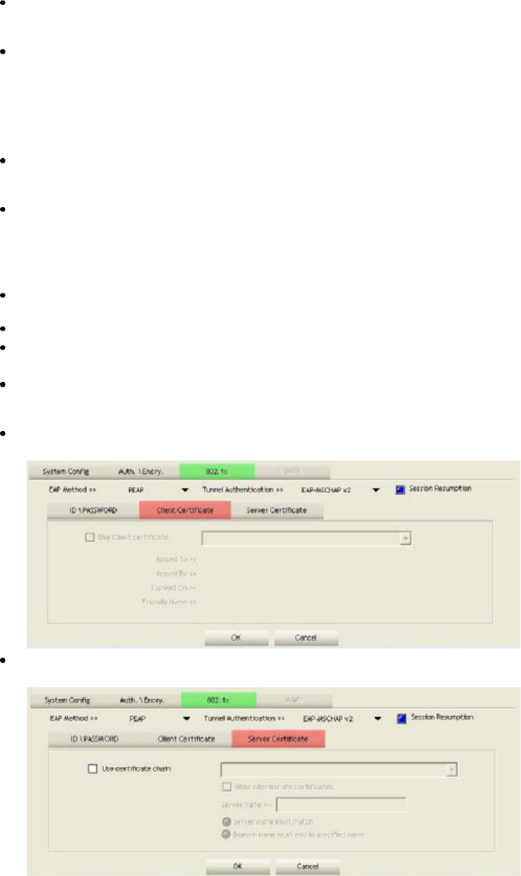
Client Certification
Use Client certificate: Client certificate for server authentication.
Server Certification
45
Certificate issuer: Select the server that issues the certificate.
Allow intermediate certificates: It must be in the server certificate chain between the server
certificate and the server specified in the "certificate issuer must be" field.
Server name: Enter an authentication sever root.
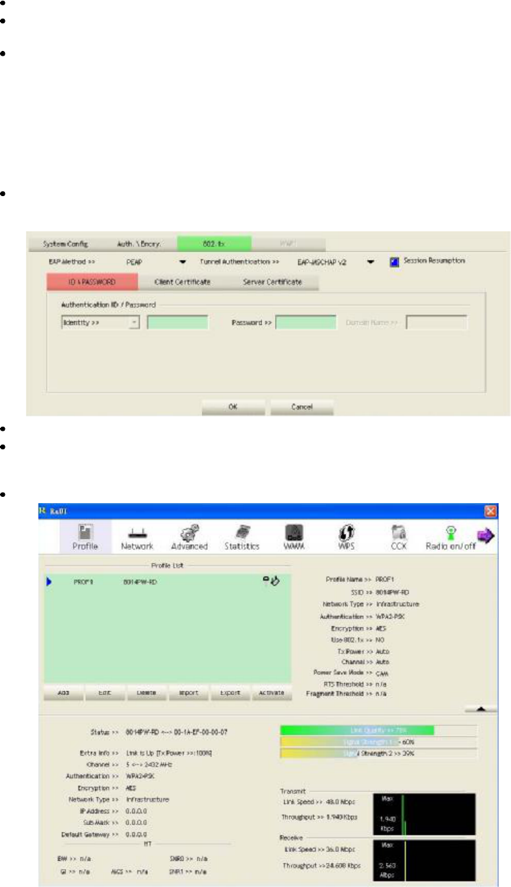
4.3.3 Example to Reconnect 802.1x Authenticated Connection after 802.1x
Authenticated connection is failed in Profile
There are two situations where a user is able to reconnect an 802.1x authenticated connection and
authenticate successfully after an 802.1x authenticated connection has failed on the profile page. They
are as follows:
When keying in an identity, password or domain name error:
Authentication type chooses "PEAP", key identity into test. Tunnel Protocol is"EAP-MSCHAP-v2,
the tunnel identity and tunnel password are tested. Those settings are the same as our intended AP's
setting.
Because of keying identity and password errors, the result will appear as in the image below.
If you want to disconnect, click "Cancel" on the Authentication Failure dialog box. If you want to
reconnect, key the identity into wpatest2. The tunnel identity is wpatest2and the tunnel password is
test2. Those setting are the same as our intended AP's setting.
Click "OK". If it has connected successfully. The result will appear as the image below.
46
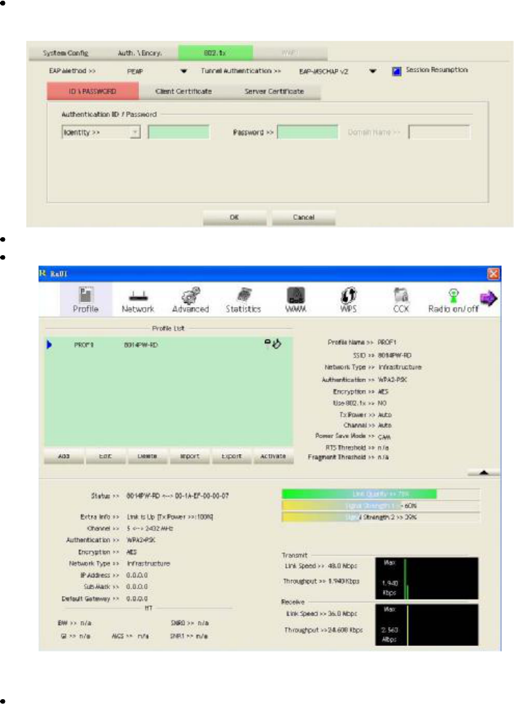
When a "Timeout" occurs;
Choose "PEAP" as the Authentication type and key-in "wpatest2" as the identity .Tunnel Protocol is
"EAP-MSCHAP-v2 and the tunnel identity is "wpatest2". The tunnel password is "test2". These
settings are the same as our intended AP's setting.
When a "Timeout" occurs, The following dialog box will be displayed;
If it has connected successfully, the dialog box will appear as follows;
4.3.4 Example to Configure Connection with WEP on
Select an AP with WEP encryption and click "Connect".
47
The Auth.\Encry. function will appear as below;
Enter 1234567890 in the Key#1 Hexadecimal field. This value is same as our intended AP's setting.
Click "OK". The dialog box will appear as below;
48
49
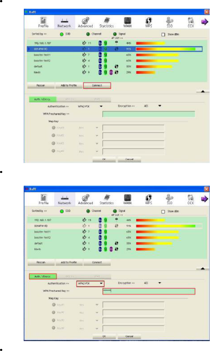
4.3.5Example to Configure connection with WPA-PSK
Select the AP with a WPA-PSK authentication mode and click "Connect .
Select WPA-PSK as the Authentication Type. Select TKIP or AES encryption. Enter the WPA
Pre-Shared Key.
Click "OK . Be careful, if the WPA Pre-Shared Key entered is not correct, you won#t be able to
exchange any data frames, even though the AP can be connected.
50
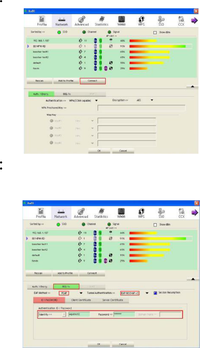
4.3.6Example to configure connection with WPA
Select an AP with WPA authentication mode and click "Connect .
Select WPA as the Authentication Type.
Click "802.1x and the setting page will appear.
1. PEAP:
Select "EAP-MSCHAP v2 from the drop-down list for tunnel authentication and key-in the tunnel
identity as "wpatest2 and the tunnel password as "test2 . These settings are the same as our intended
AP#s setting. Then click OK.
51
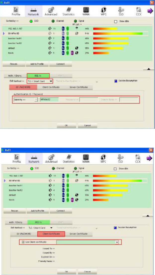
2. TLS/Smart Card:
Select TLS/Smart Card from the Authentication type drop-down list. TLS only requires the
identification to be set as "wpatest2 for server authentication.
TLS must use client certification. Click "Client Certification and select a certification for server
authentication. Then click OK.
52
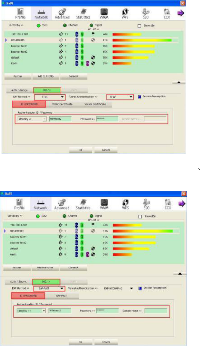
3. TTLS:
Select TTLS from the Authentication type drop-down list. Key-in the identity as "wpatest2 and
password. These settings are the same as our intended AP#s setting. Then click OK.
4. EAP-FAST:
Select EAP-FAST from the Authentication type drop-down list. Key-in the identity as "wpatest2
password and a domain name into the blank field. These settings are the same as our intended AP#s
setting. Then click OK.
53
54
5. Trouble Shooting
This chapter provides solutions to problems that may occur during the installation and operation of PCI
Adapter. Read the descriptions below to solve your problems.
1. The PCI Adapter does not work properly.
Reinsert PCI Adapter into your PC#s PCI slot. Right click on My Computer and select Properties.
Select the device manager and click on the Network Adapter. You will find PCI Adapter if it is installed
successfully. If you see the yellow exclamation mark, the resources are conflicting. You will see the
status of PCI Adapter. If there is a yellow question mark, please check the following: Make sure that
your PC has a free IRQ (Interrupt Request, a hardware interrupt on a PC.) Make sure that you have
inserted the right adapter and installed the proper driver. If PCI Adapter does not function after
attempting the above steps, remove it and do the following: Uninstall the driver software from your PC.
Restart your PC and repeat the hardware and software installation as specified in this User Guide.
2. I cannot communicate with the other computers linked via Ethernet in the Infrastructure
configuration.
Make sure that the PC to which PCI Adapter is associated is powered on. Make sure that PCI Adapter
is configured on the same channel and with the same security options as with the other computers in
the Infrastructure configuration.
3. What should I do when the computer with PCI Adapter installed is unable to connect to the
wireless network and/or the Internet?
Check that the LED indicators for the broadband modem are indicating normal activity. If not, there
may be a problem with the broadband connection. Check that the LED indicators on the wireless router
are functioning properly. If not, check that the AC power and Ethernet cables are firmly connected.
Check that the IP address, subnet mask, gateway, and DNS settings are correctly entered for the
network. In Infrastructure mode, make sure the same Service Set Identifier (SSID) is specified on the
settings for the wireless clients and access points. In Ad-Hoc mode, both wireless clients will need to
have the same SSID. Please note that it might be necessary to set up one client to establish a BSS
(Basic Service Set) and wait briefly before setting up other clients. This prevents several clients from
trying to establish a BSS at the same time, which can result in multiple singular BSSs being established,
rather than a single BSS with multiple clients associated to it. Check that the Network Connection for
the wireless client is configured properly. If Security is enabled, make sure that the correct encryption
keys are entered on both PCI Adapter and the access point.

FCC ID: VYTLP-7665
FCC Compliance and Advisory Statement
This device complies with Part 15 of the FCC rules. Operation is subject to the following two
conditions:(1) this device may not cause harmful interference, and (2) this device must accept
any interference received, including interference that may cause undesired operation.
This equipment has been tested and found to comply with the limits for a Class B digital device,
according to Part 15 of the FCC rules. These limits are designed to provide reasonable
protection against harmful interference in a residential installation. This equipment generates,
uses and can radiate radio frequency energy and if not installed and used in accordance with
the instructions, may cause harmful interference to radio communications. However, there is
no guarantee that interference will not occur in a particular installation. If this equipment does
cause harmful interference to radio or television reception, which can be determined by turning
the equipment off and on, the user is encouraged to try correct the interference by one or more
of the following measures:
1.Reorient the receiving antenna.
2.Increase the separation between the equipment and receiver.
3.Connect the equipment into and outlet on a circuit different from that to which the receiver is
connected.
4.Consult the dealer or an experienced radio/TV technician for help.
Any special accessories needed for compliance must be specified in the instruction manual.
Warning: A shielded-type power cord is required in order to meet FCC emission limits and
also to prevent interference to the nearby radio and television reception. It is essential that
only the supplied power cord be used. Use only shielded cables to connect I/O devices to this
equipment.
CAUSION: Any changes or modifications not expressly approved by the party responsible for
compliance could void your authority to operate the equipment.