Loopcomm Technology LP-8696C LP-8696C 802.11n WIRELESS AP ROUTER User Manual User s Manual of WLAN Broadband router 1T2R
Loopcomm Technology,.Inc. LP-8696C 802.11n WIRELESS AP ROUTER User s Manual of WLAN Broadband router 1T2R
UserManual.wiki
>
Loopcomm Technology
>
LP 8696C User Manual
Users Manual
Navigation menu
Upload a User Manual
Namespaces
Wiki Guide
HTML
PDF
Info
Views
User Manual
Discussion / Help
Navigation
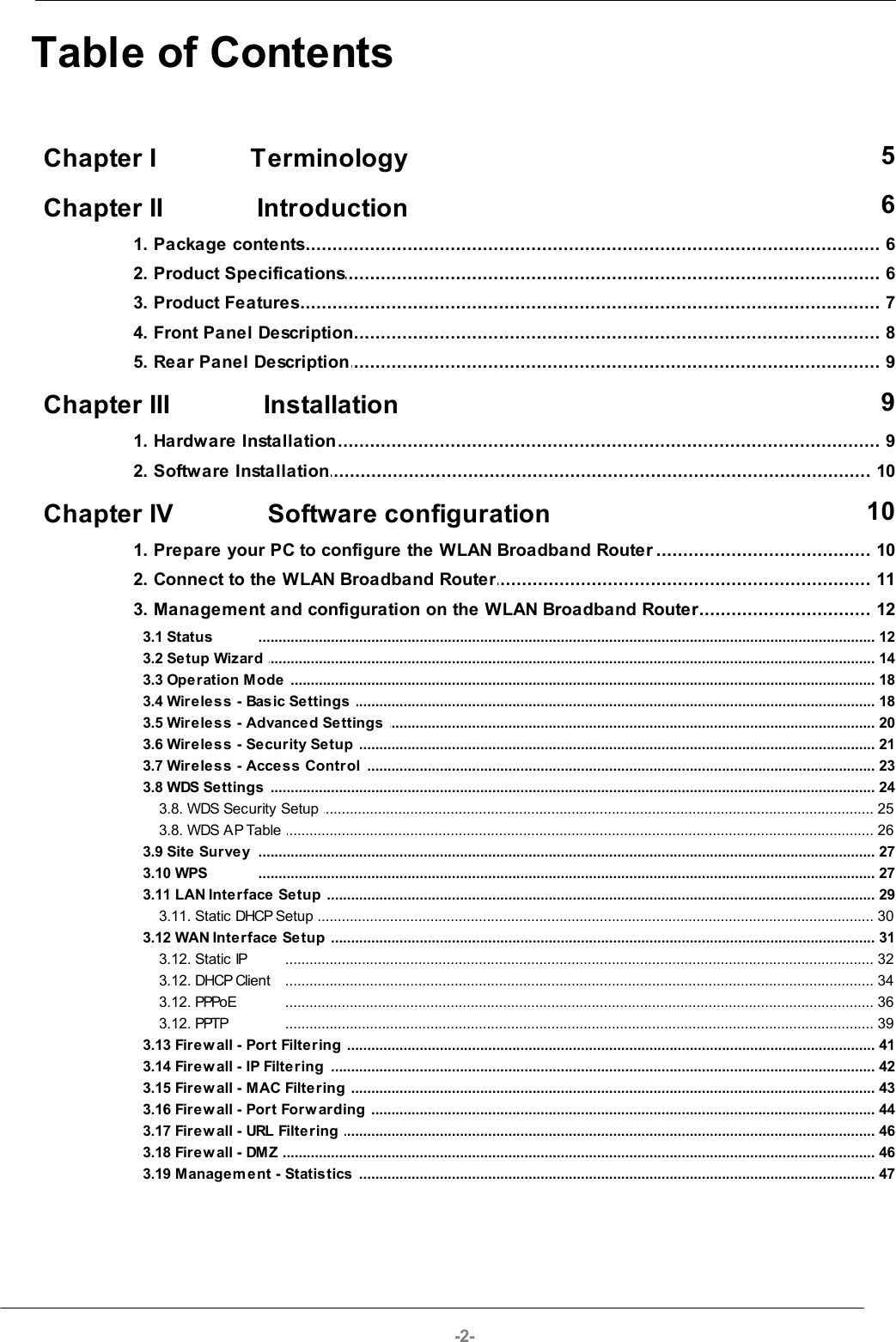
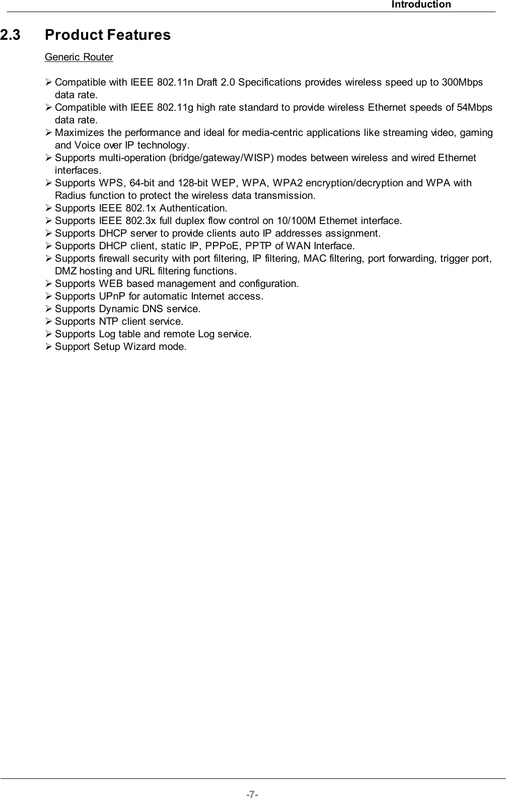
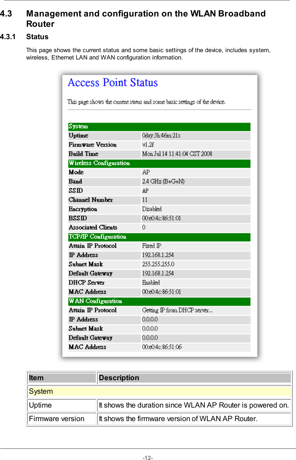
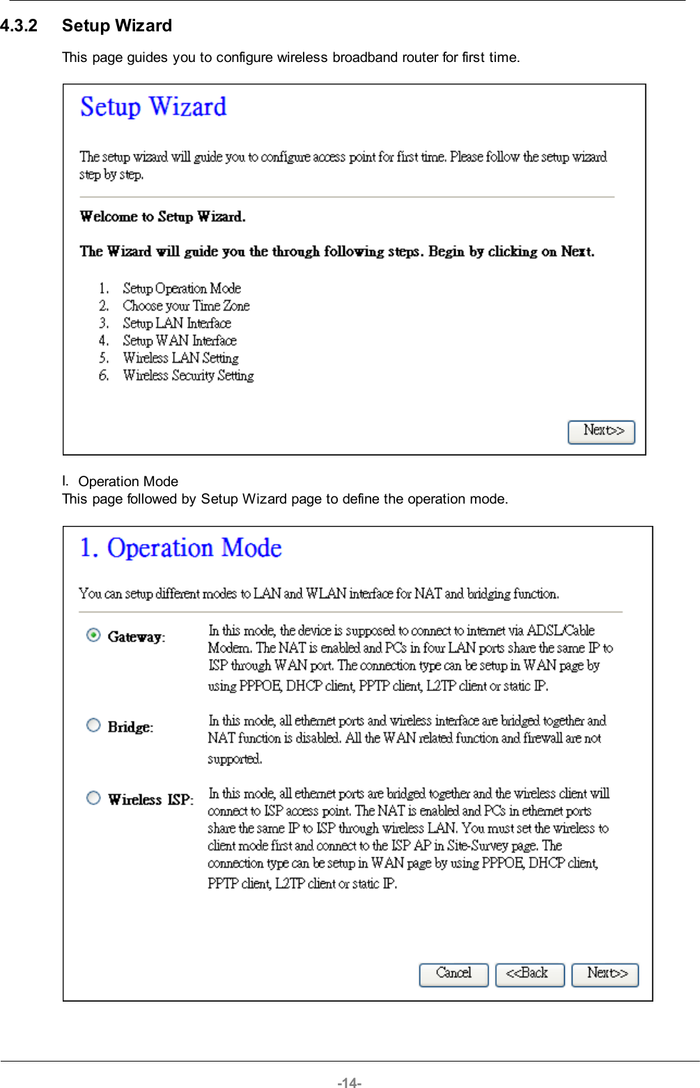
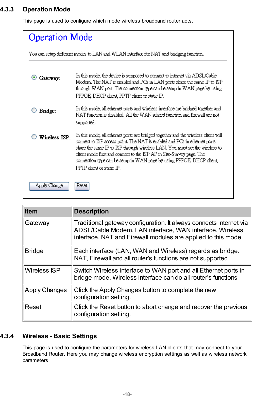
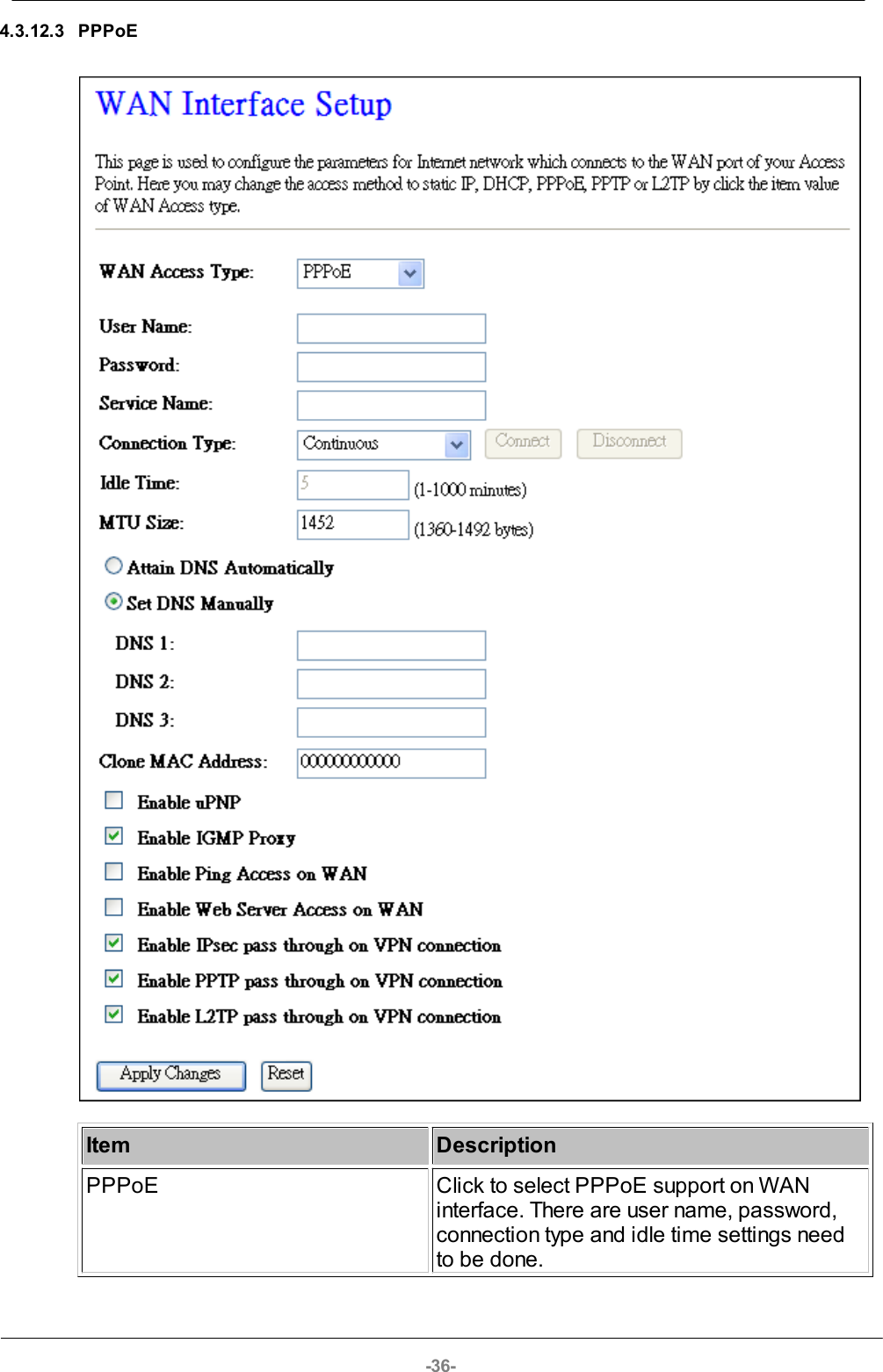
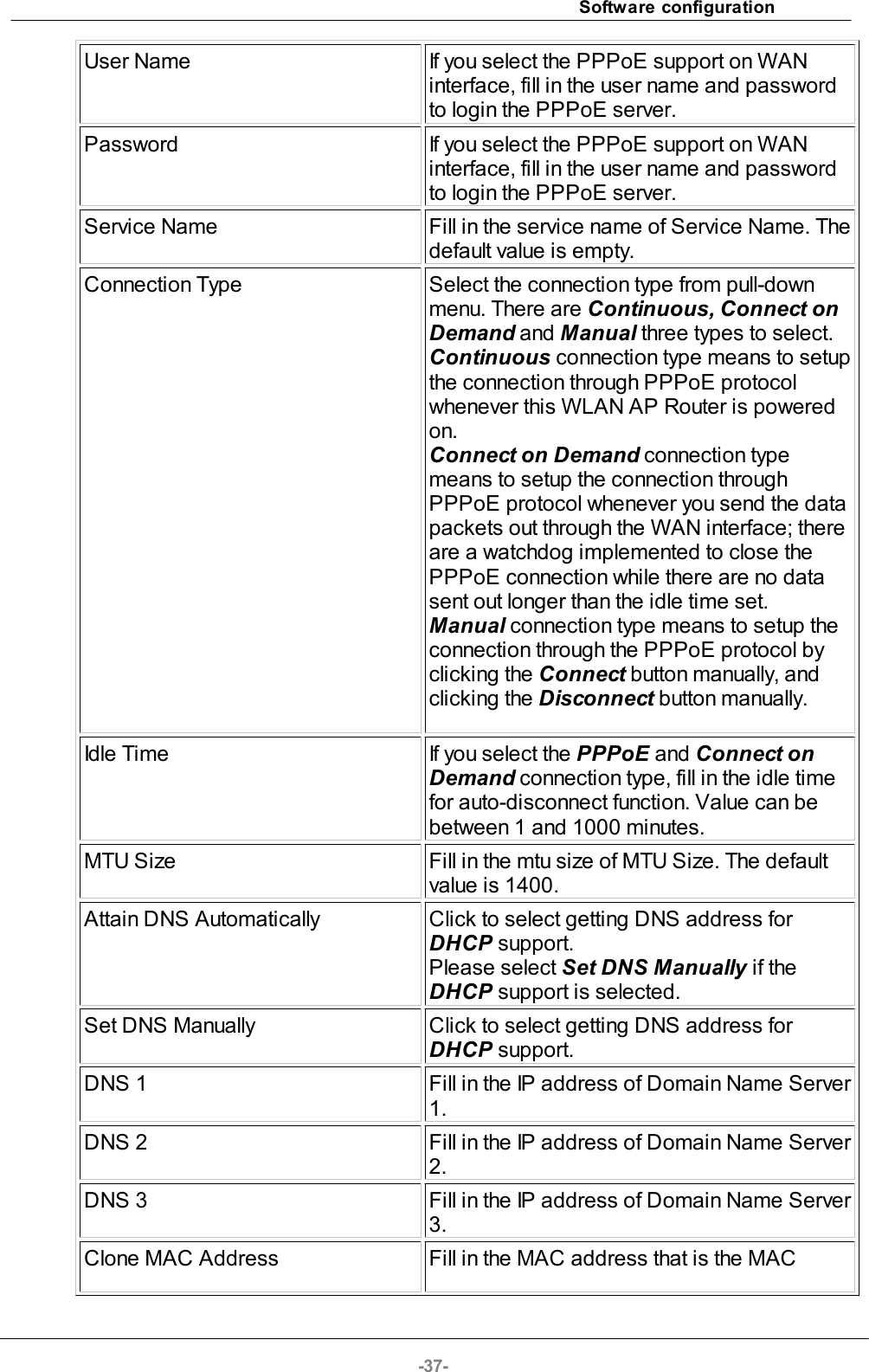
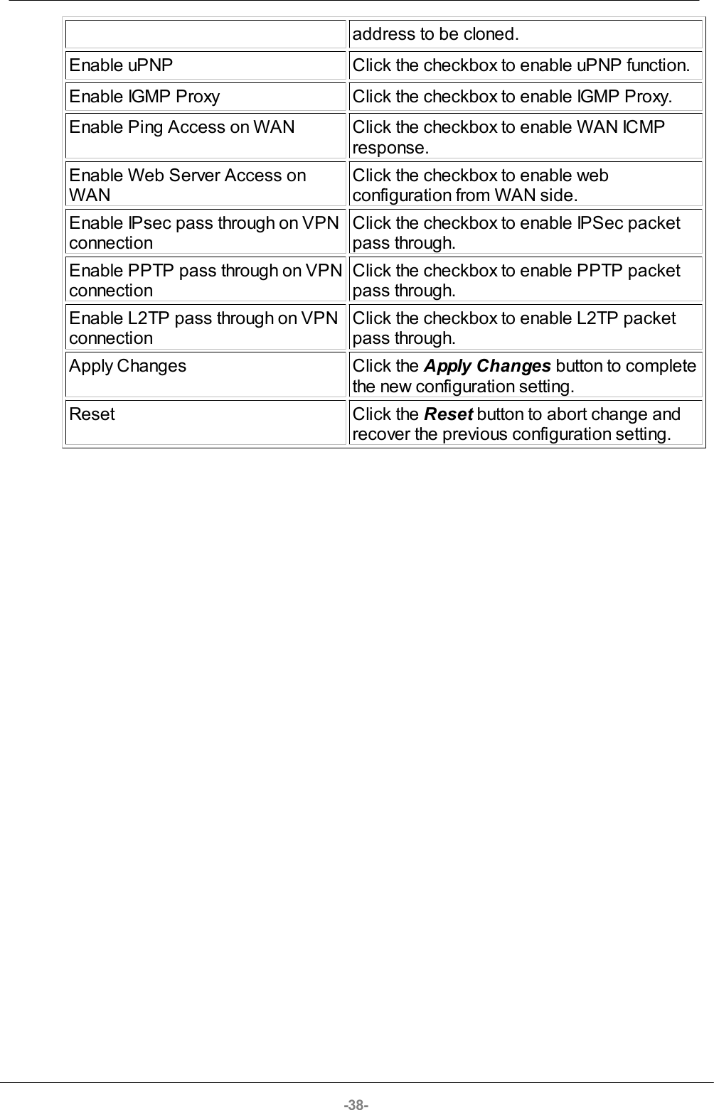
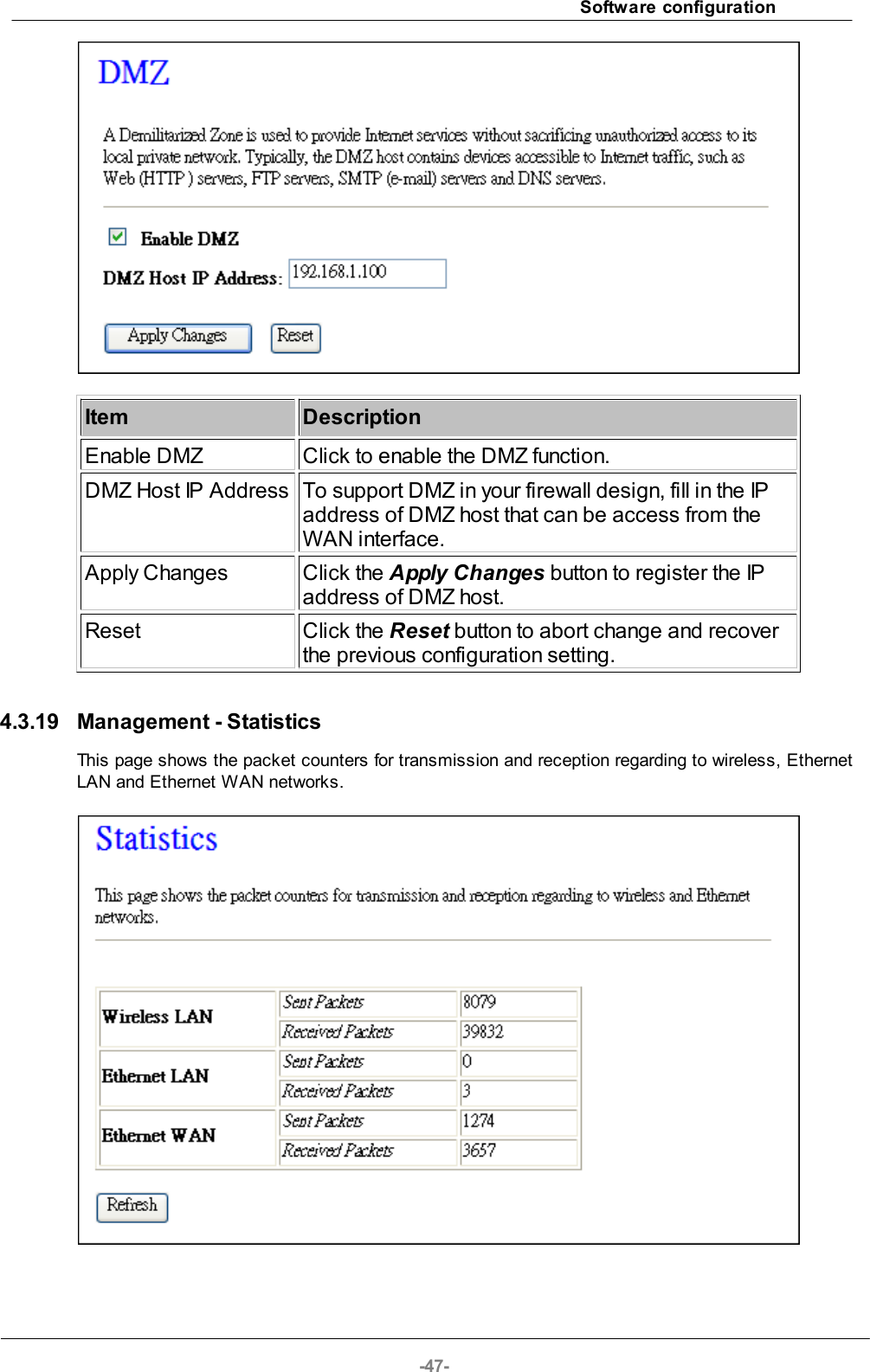
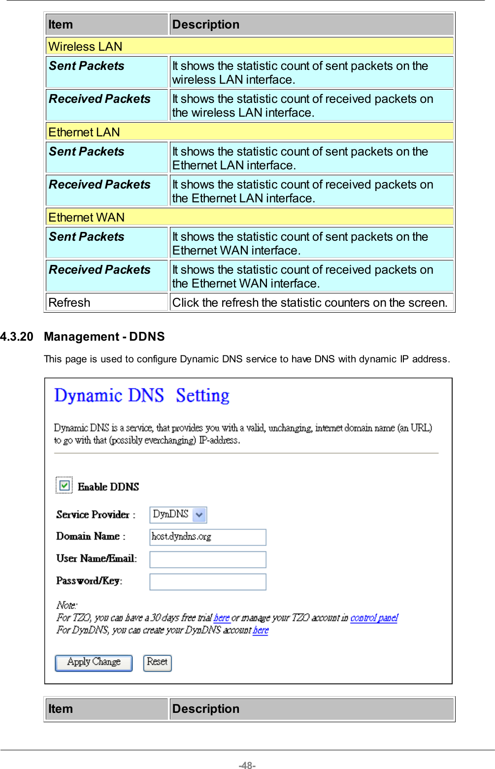
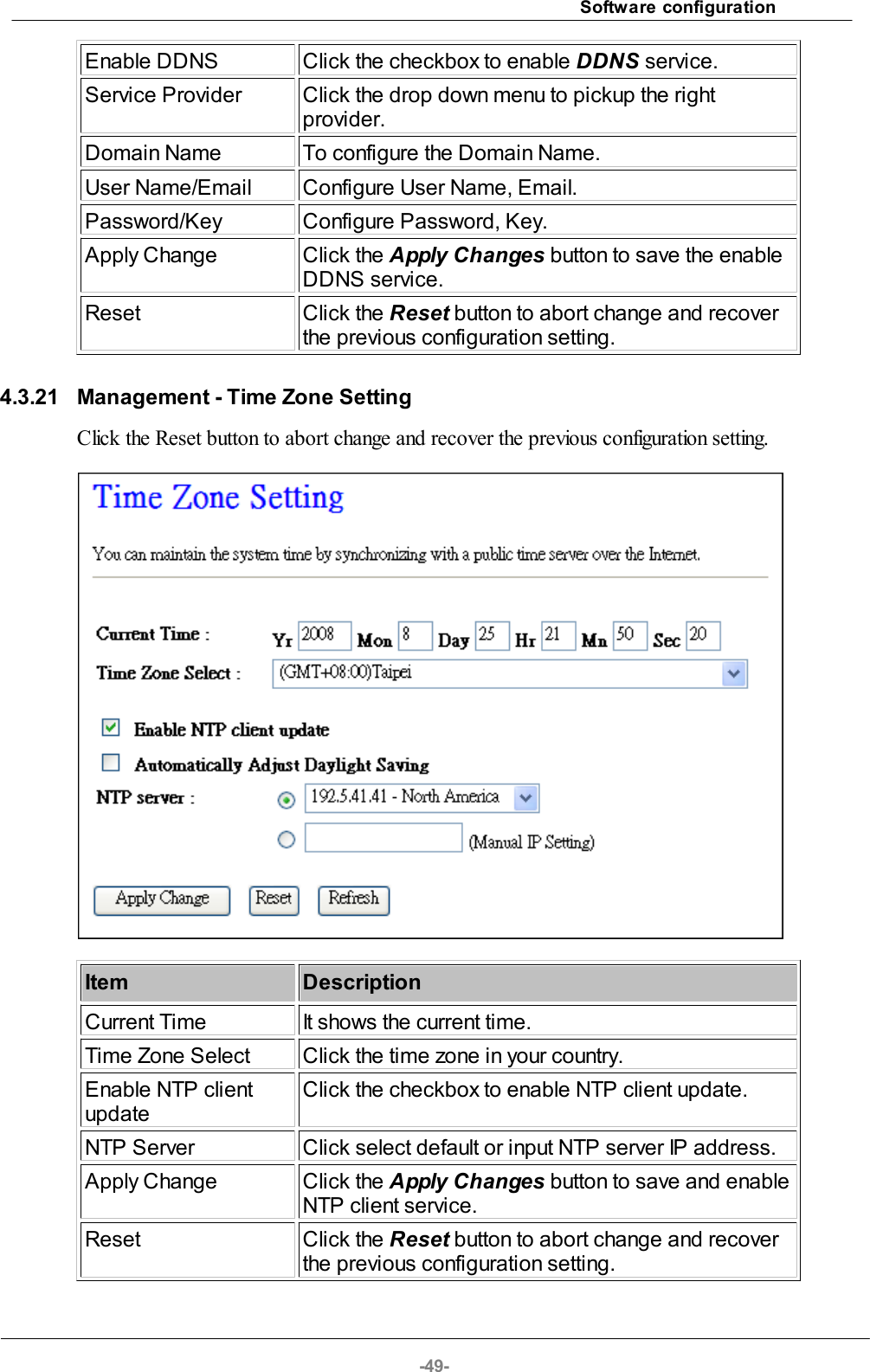
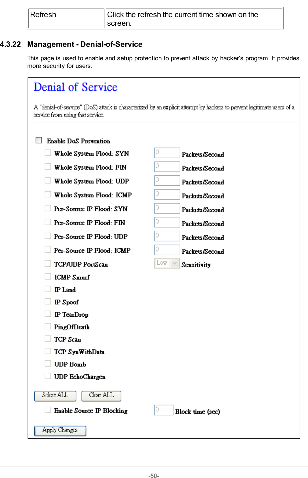
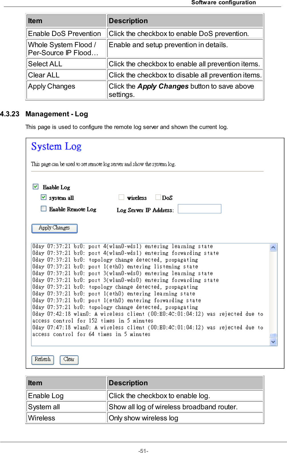
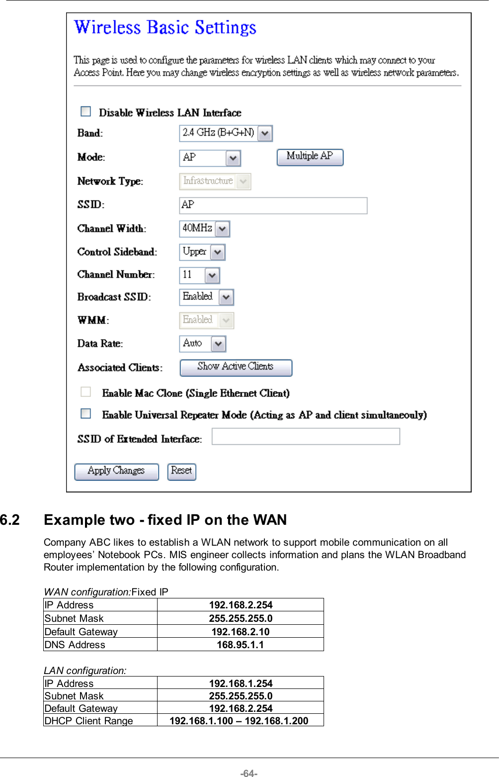
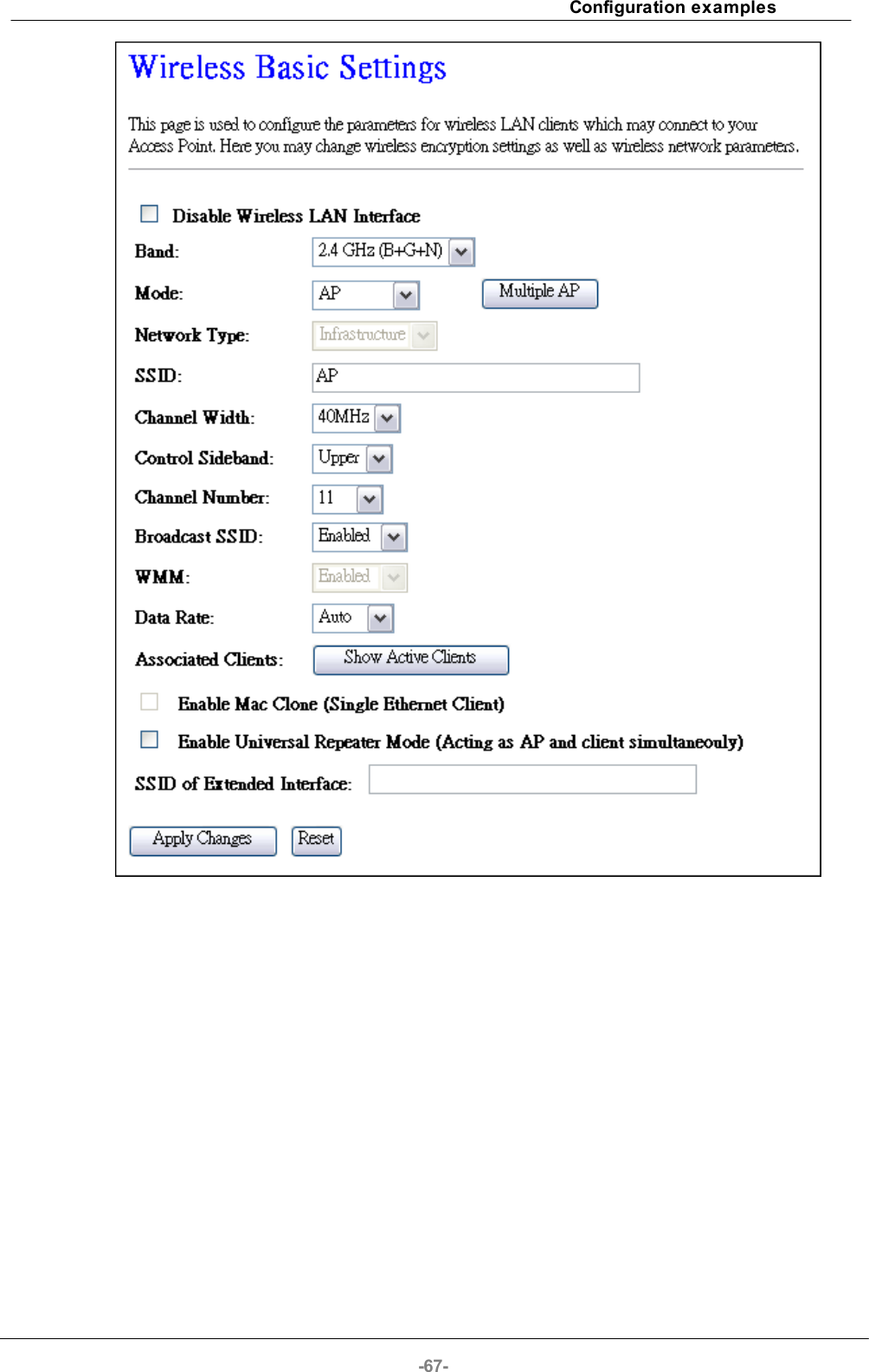
![Software configuration-19-ItemDescriptionDisable Wireless LAN InterfaceClick on to disable the wireless LAN data transmission.BandClick to select 2.4GHz(B) / 2.4GHz(G) / 2.4GHz(N) /2.4GHz(B+G)/ 2.4GHz(G+N) / 2.4GHz(B+G+N)ModeClick to select the WLAN AP / Client / WDS /AP+WDS wireless mode.Network TypeWhile Mode is selected to be Client. Click to select thenetwork type infrastructure or Ad hoc.SSIDIt is the wireless network name. The SSID can be 32bytes long.Channel WidthSelect the operating channel width 20 MHz or 40 MHz.[N band only]Control SidebandSelect the Sideband with Upper or Lower for channelwidth 40MHz. [N band only]](https://usermanual.wiki/Loopcomm-Technology/LP-8696C/User-Guide-1386951-Page-19.png)
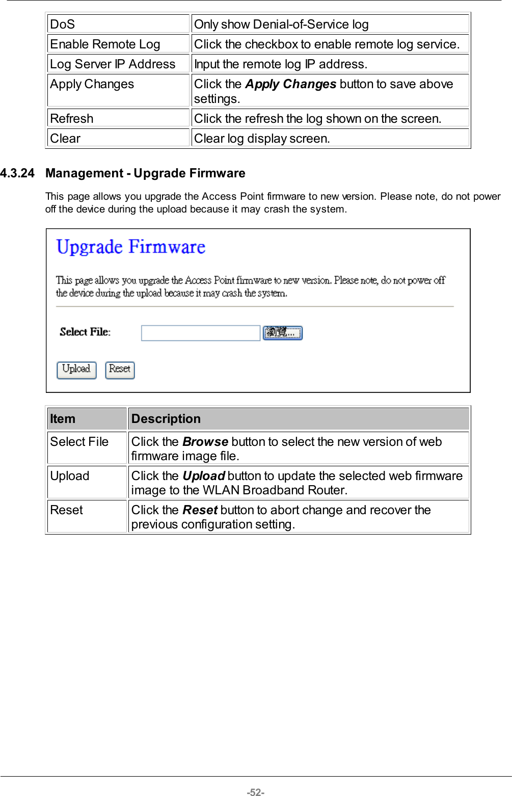
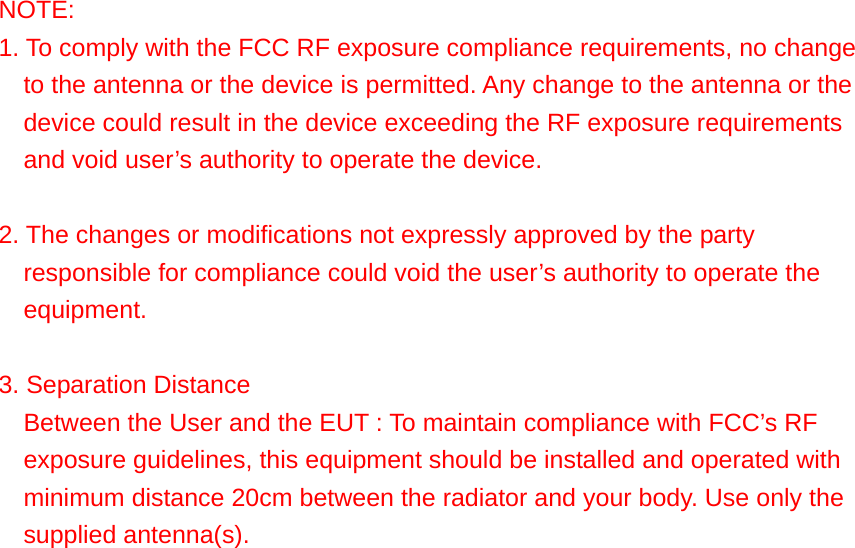
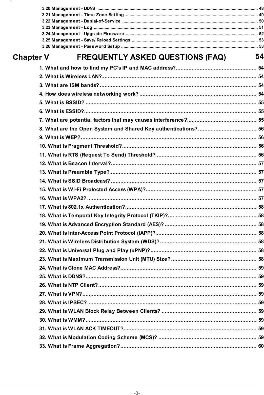
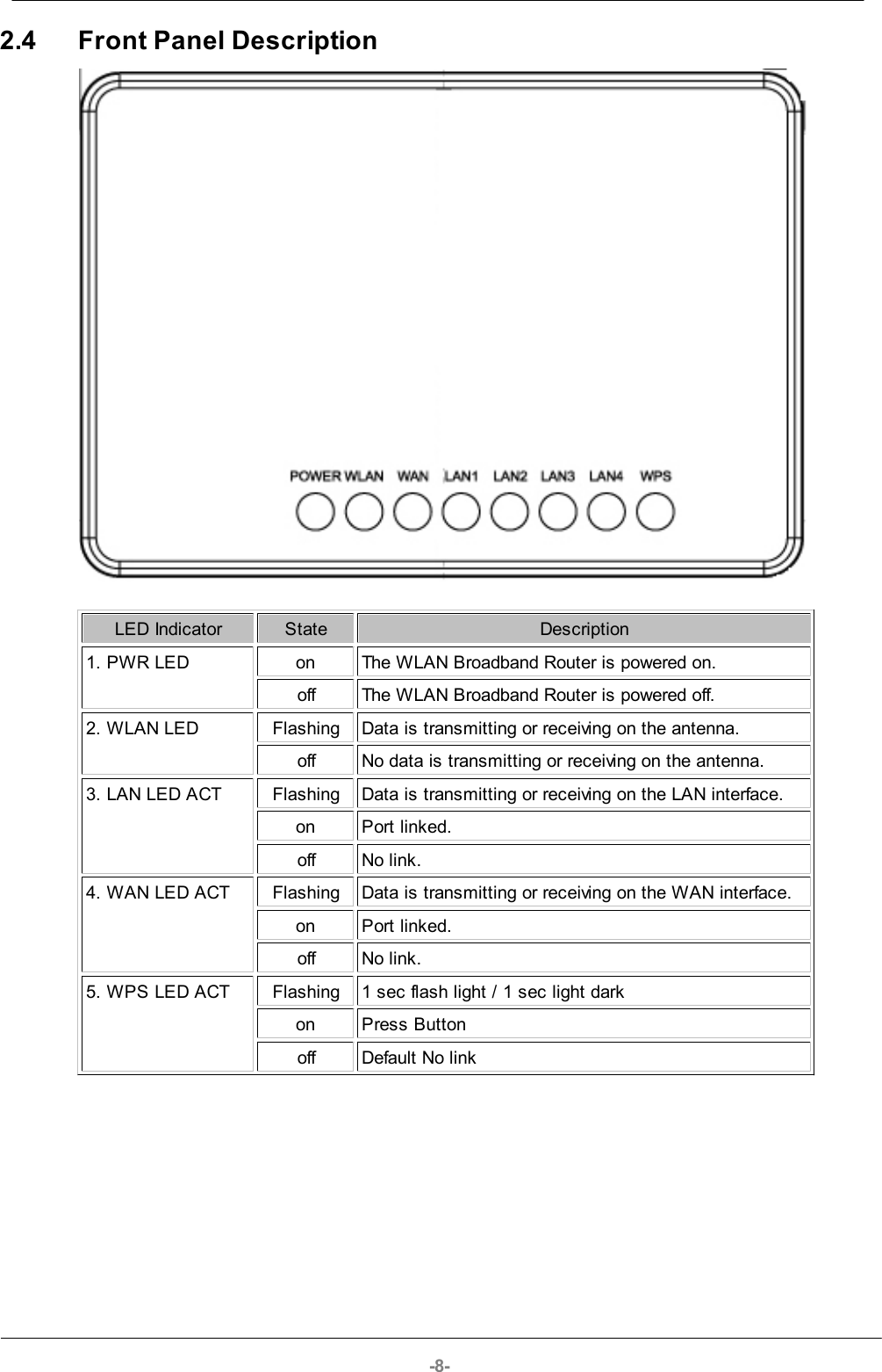
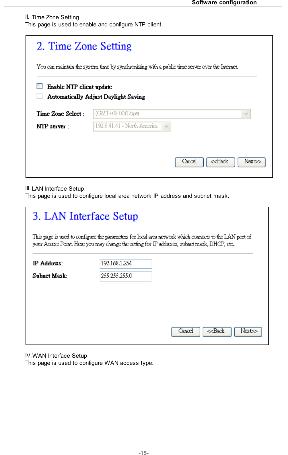
![-20-Channel NumberSelect the wireless communication channel from pull-down menu.Broadcast SSIDClick to enable or disable the SSID broadcast function.WMMClick Enabled/Disabled to init WMM feature.Data RateSelect the transmission data rate from pull-down menu.Data rate can be auto-select, 1M to 54Mbps or MCS.Associated Clients Click the Show Active Clients button to open ActiveWireless Client Table that shows the MAC address,transmit-packet, receive-packet and transmission-ratefor each associated wireless client.Enable Mac Clone(Single Ethernet Client)Take Laptop NIC MAC address as wireless clientMAC address. [Client Mode only]SSID of ExtendedClick to enable Universal Repeater ModeInterfaceAssign SSID when enables Universal Repeater Mode.Apply ChangesClick the Apply Changes button to complete the newconfiguration setting.ResetClick the Reset button to abort change and recover theprevious configuration setting.4.3.5 Wireless - Advanced SettingsThese settings are only for more technically advanced users who have a sufficient knowledge aboutwireless LAN. These settings should not be changed unless you know what effect the changes willhave on your WLAN Broadband Router.](https://usermanual.wiki/Loopcomm-Technology/LP-8696C/User-Guide-1386951-Page-20.png)
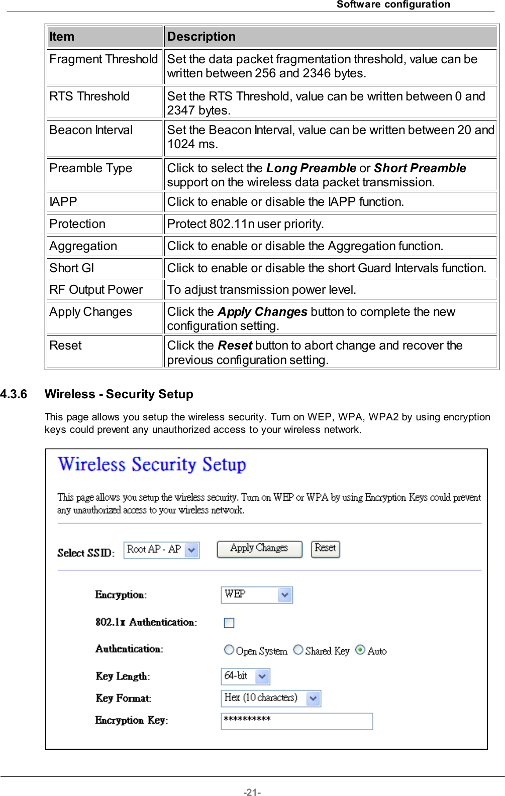
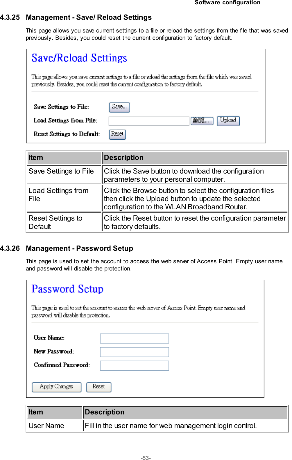
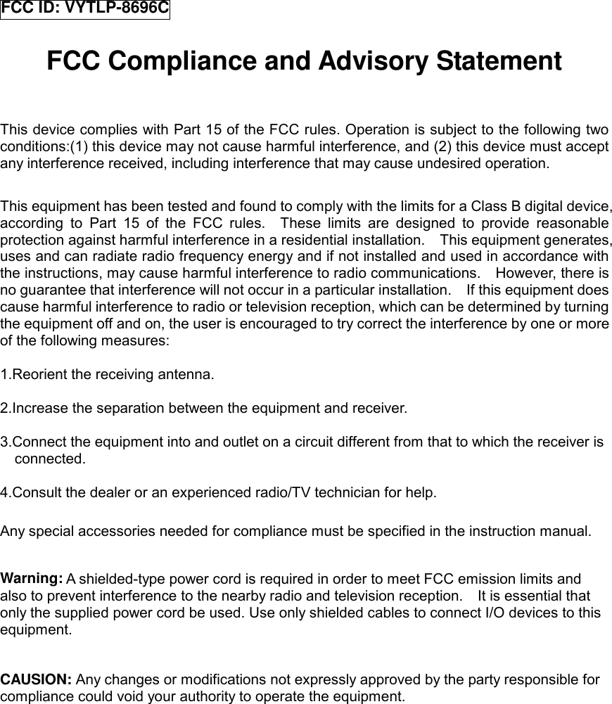
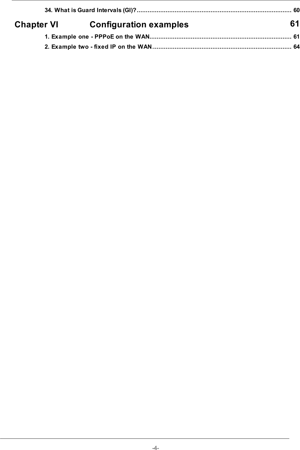
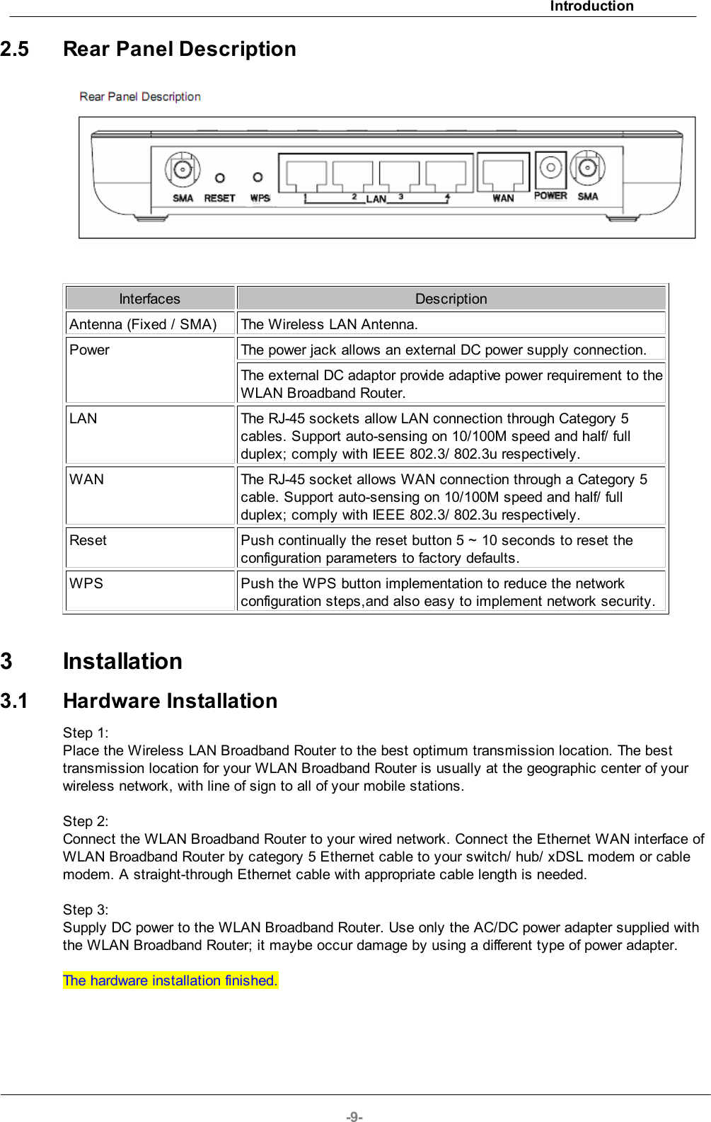
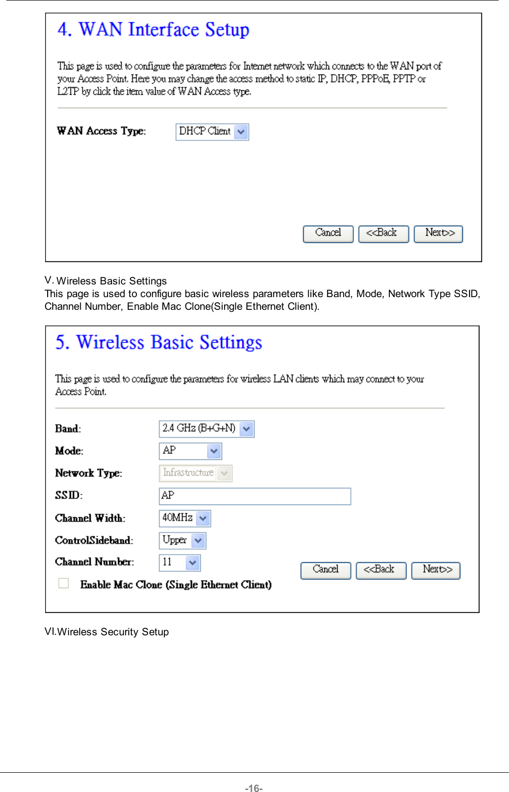
![-22-ItemDescriptionSelect SSIDSelect the SSID from multiple APs.EncryptionSelect the encryption supported over wireless access. Theencryption method can be None, WEP, WPA, WPA2 orWPA-Mixed.Use 802.1xAuthenticationWhile Encryption is selected to be WEP. Click the check boxto enable IEEE 802.1x authentication function.Authentication TypeClick to select the authentication type in Open System,Shared Key or Auto selection.Key LengthSelect the WEP shared secret key length from pull-downmenu. The length can be chose between 64-bit and 128-bit(known as “WEP2”) keys.The WEP key is composed of initialization vector (24 bits)and secret key (40-bit or 104-bit).Key FormatSelect the WEP shared secret key format from pull-downmenu. The format can be chose between plant text (ASCII)and hexadecimal (HEX) code.Encryption KeySecret key of WEP security encryption function.WPA AuthenticationModeWhile Encryption is selected to be WPA. Click to select theWPA Authentication Mode with Enterprise (RADIUS) orPersonal (Pre-Shared Key).WPA Cipher SuiteSelect the Cipher Suite for WPA encryption.WPA2 Cipher SuiteSelect the Cipher Suite for WPA2 encryption.Pre-Shared KeyFormatWhile Encryption is selected to be WPA.Select the Pre-shared key format from the pull-down menu.The format can be Passphrase or Hex (64 characters).[WPA, Personal(Pre-Shared Key) only]Pre-Shared KeyFill in the key value. [WPA, Personal(Pre-Shared Key)only]Enable Pre-AuthenticationClick to enable Pre-Authentication. [WPA2/WPA2 Mixed only, Enterprise only]AuthenticationRADIUS ServerSet the IP address, port and login password information ofauthentication RADIUS sever.Apply Changes Click the Apply Changes button to complete the newconfiguration setting.Reset Click the Reset button to abort change and recover theprevious configuration setting.WEP encryption key (secret key) length: Format Length](https://usermanual.wiki/Loopcomm-Technology/LP-8696C/User-Guide-1386951-Page-22.png)
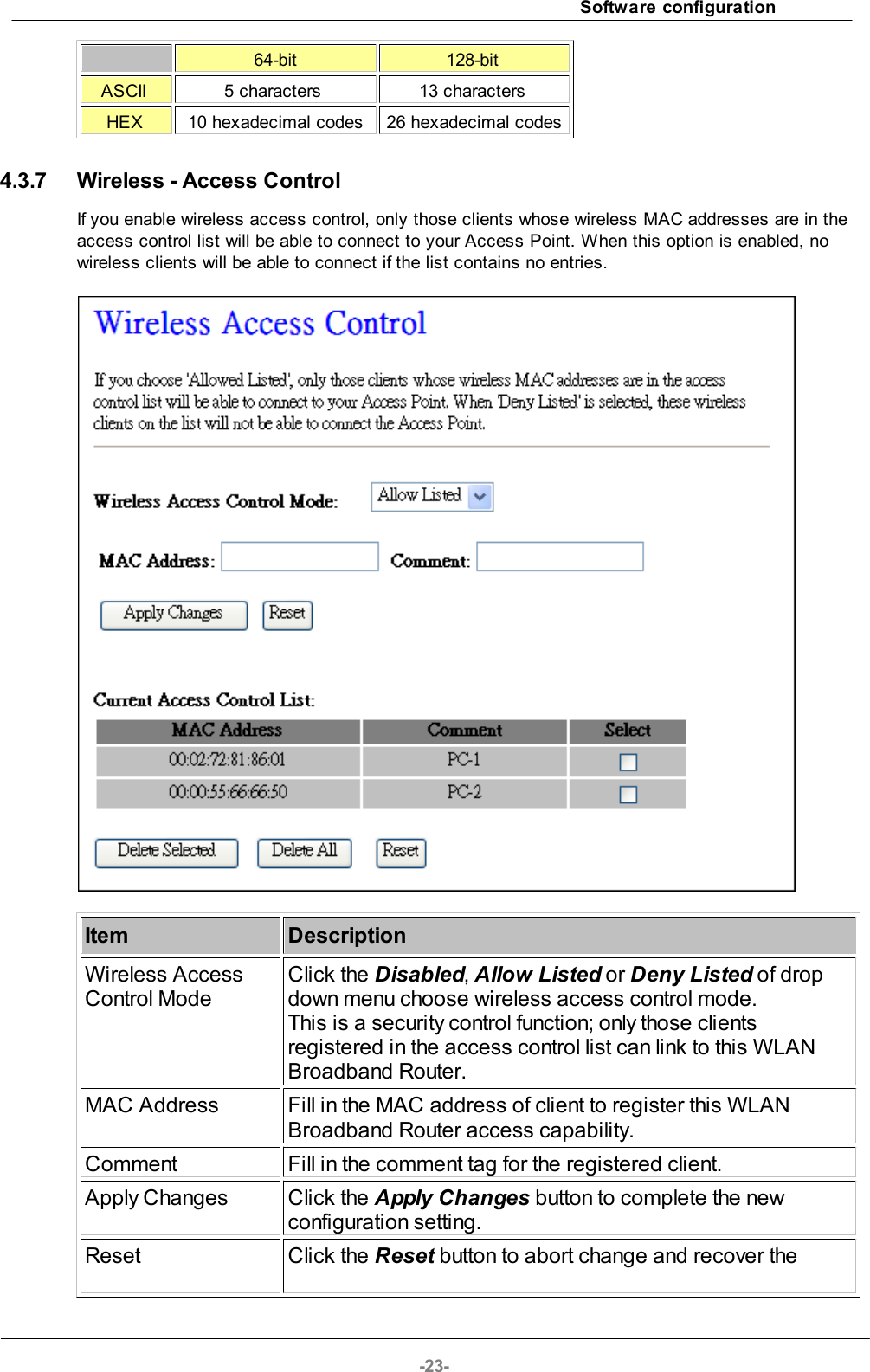
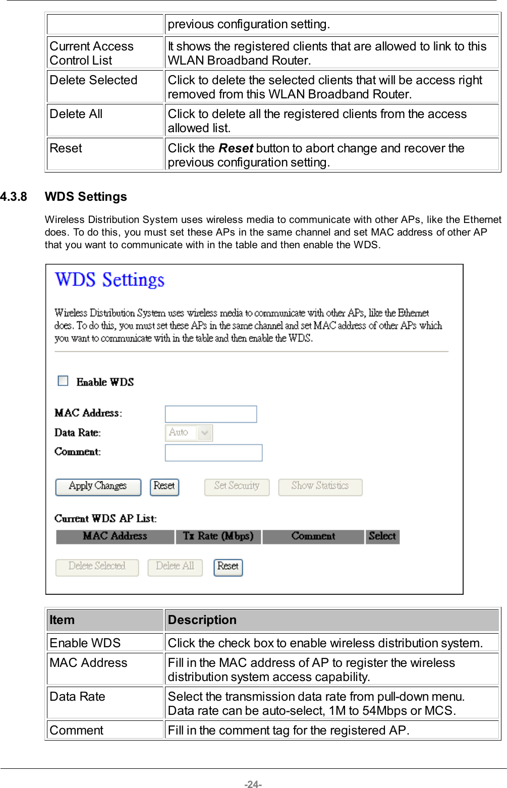
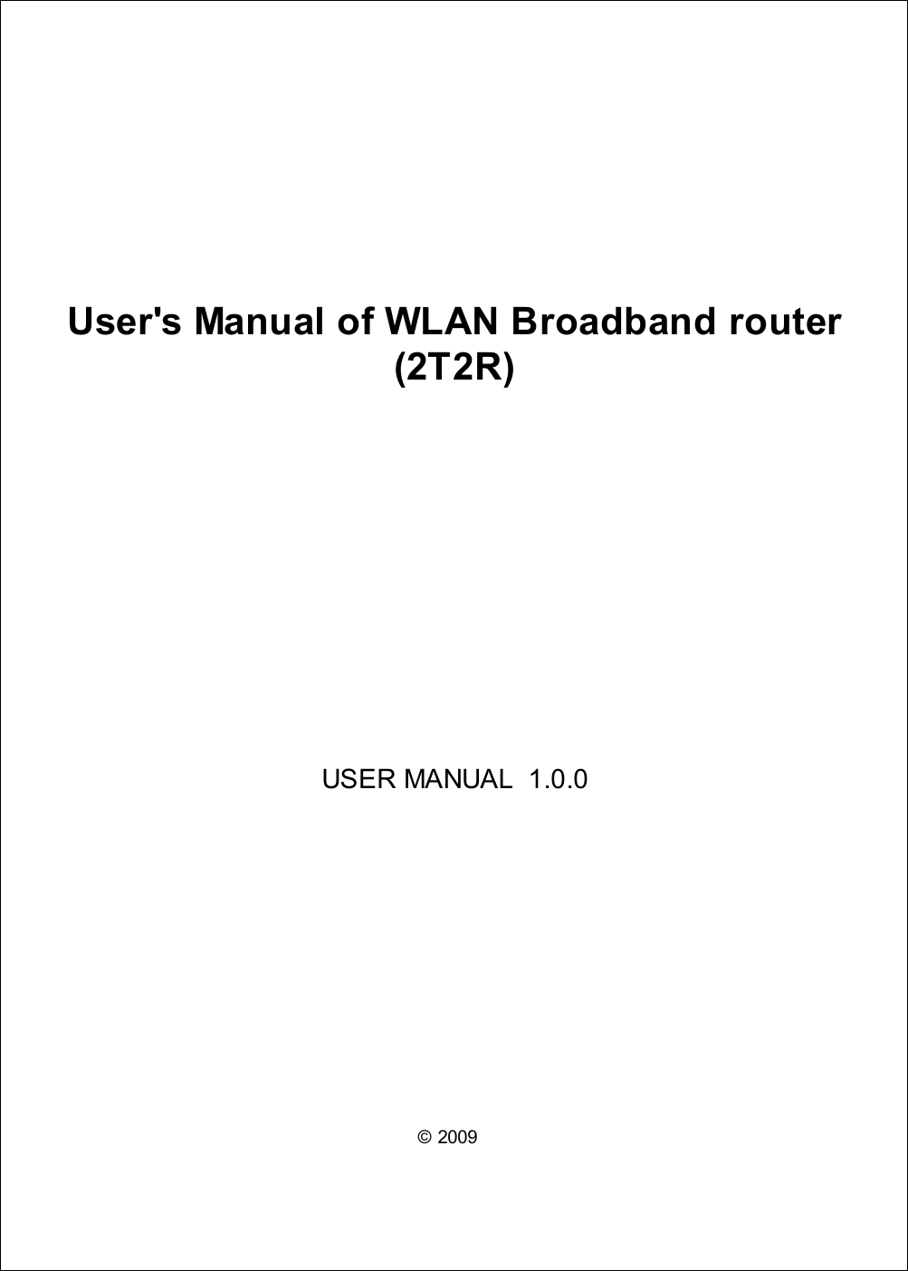
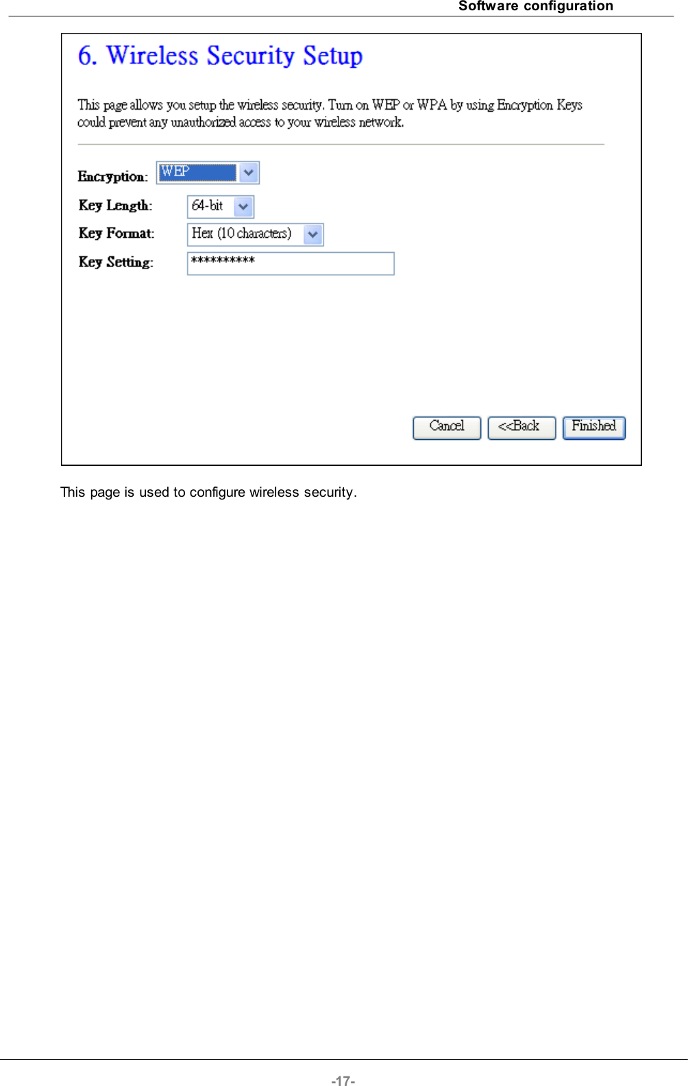
![Software configuration-25-Apply Changes Click the Apply Changes button to complete the newconfiguration setting.Reset Click the Reset button to abort change and recover theprevious configuration setting.Set SecurityClick button to configure wireless security like WEP(64bits),WEP(128bits), WPA(TKIP), WPA2(AES) or NoneShow Statistics It shows the TX, RX packets, rate statistics.Delete SelectedClick to delete the selected clients that will be access rightremoved from this WLAN Broadband Router.Delete AllClick to delete all the registered clients from the accessallowed list.ResetClick the Reset button to abort change and recover theprevious configuration setting.4.3.8.1 WDS Security SetupRequirement: Set [Wireless]->[Basic Settings]->[Mode]->AP+WDSThis page is used to configure the wireless security between APs.](https://usermanual.wiki/Loopcomm-Technology/LP-8696C/User-Guide-1386951-Page-25.png)
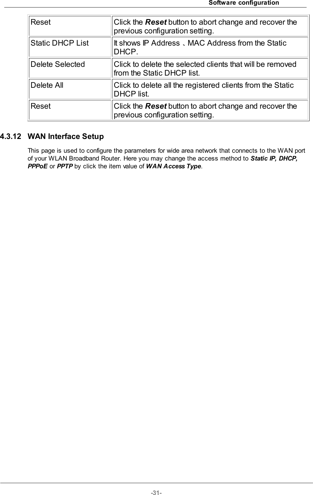
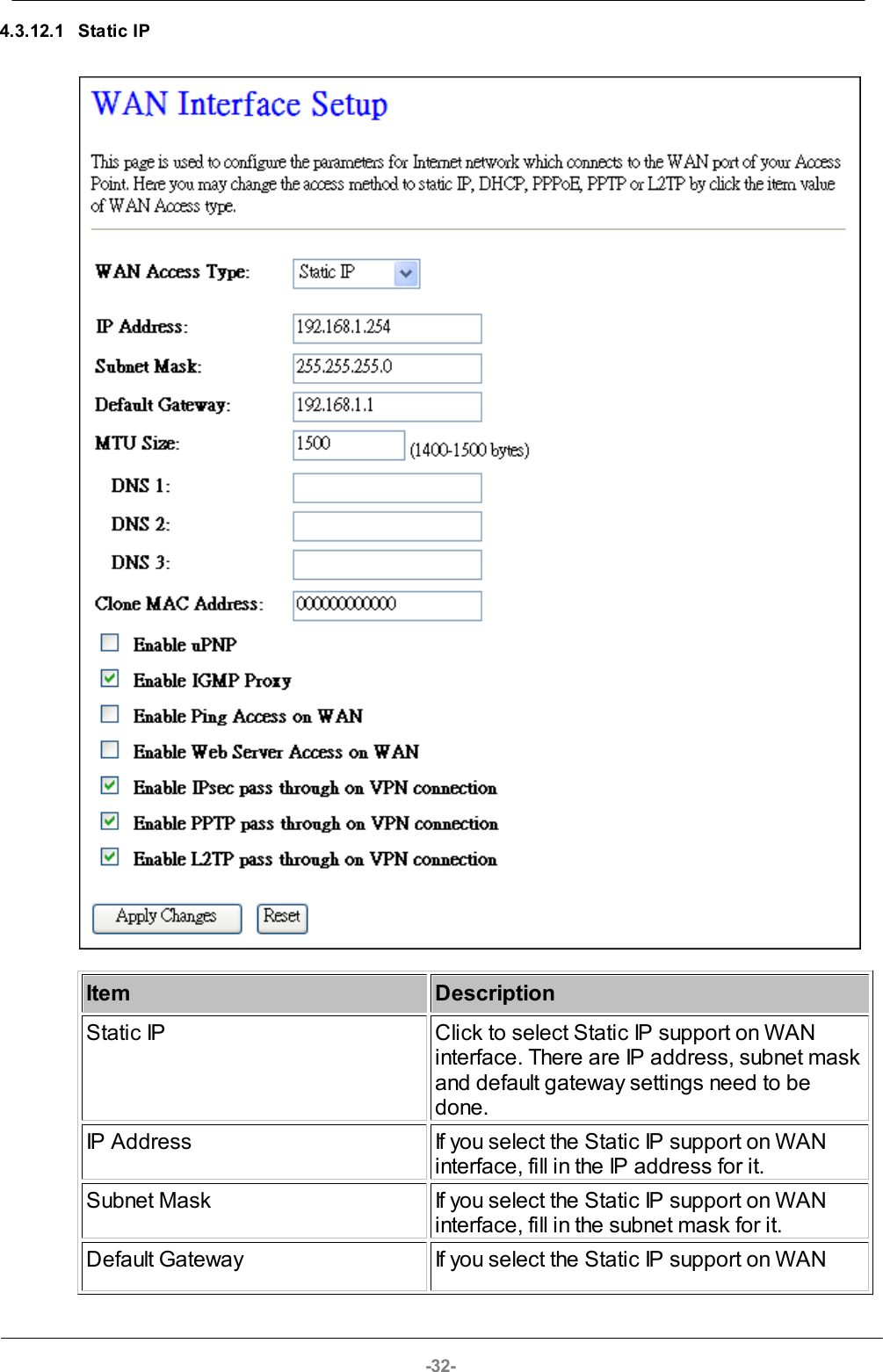
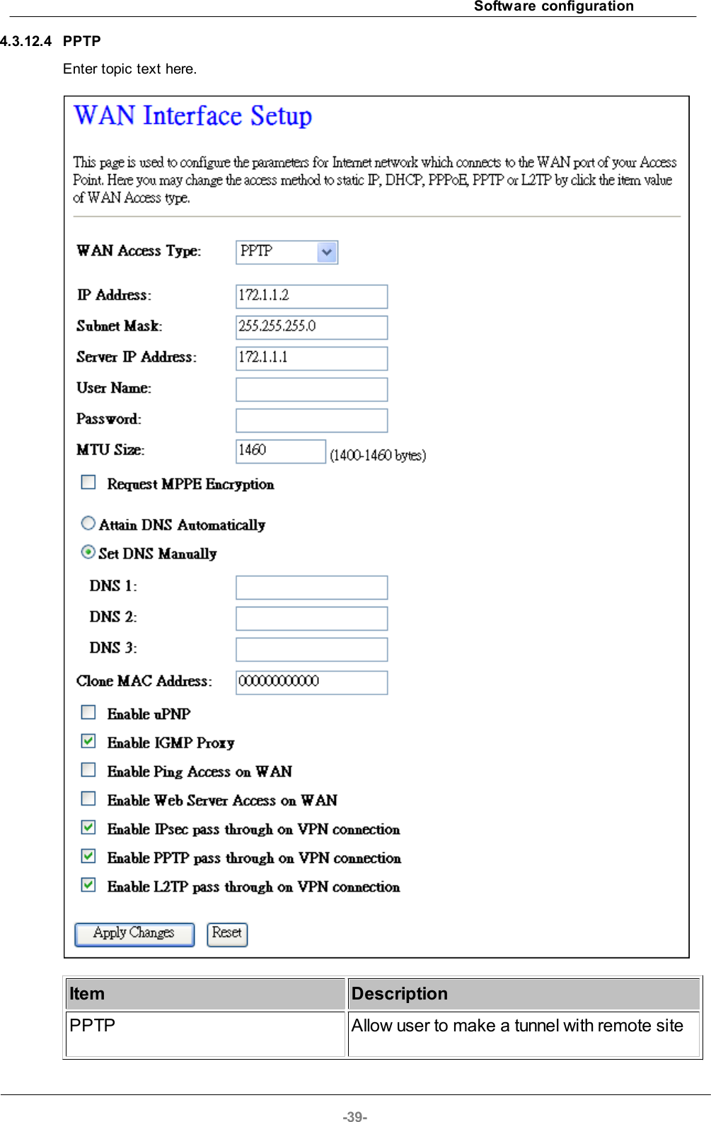
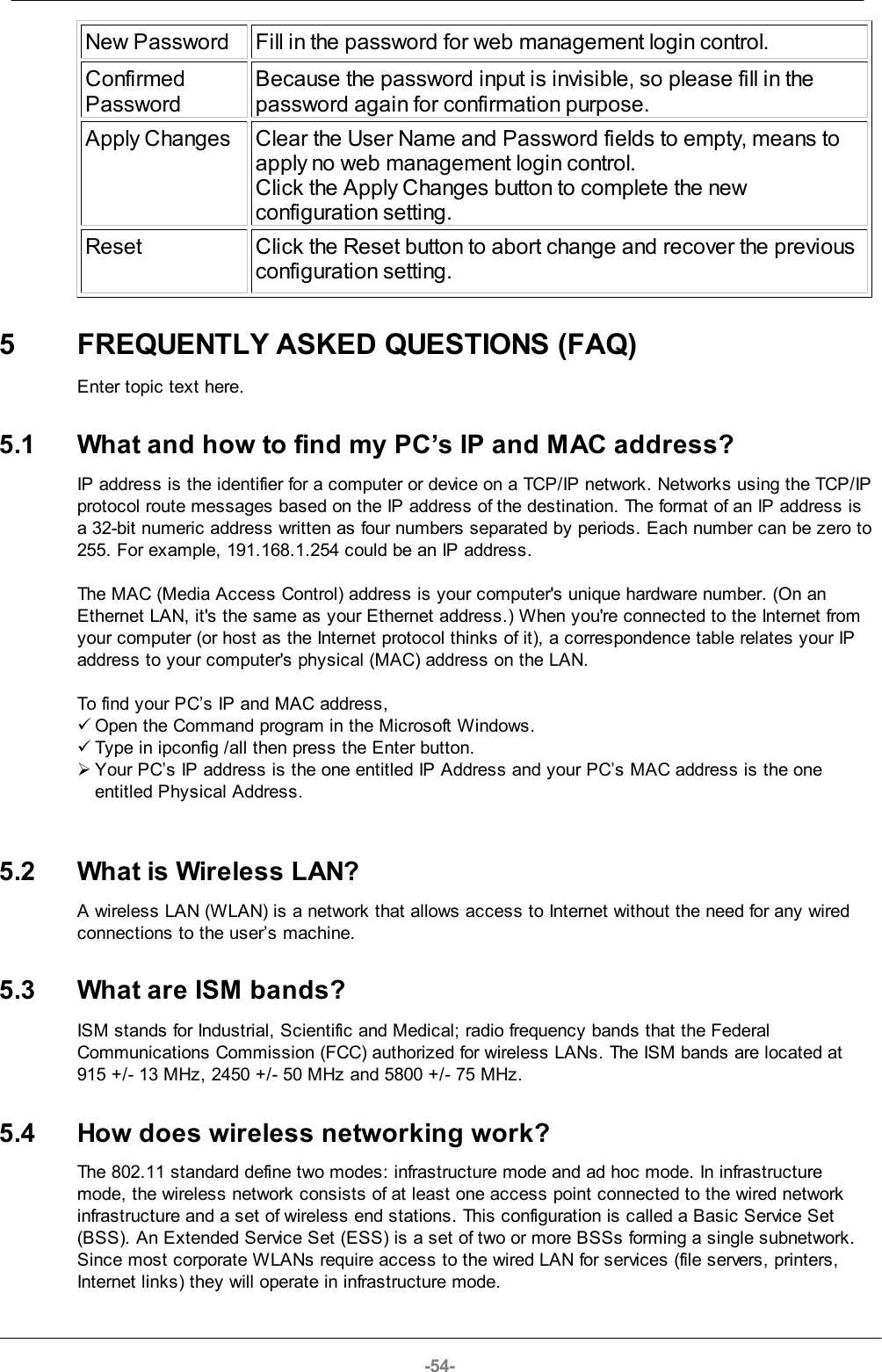
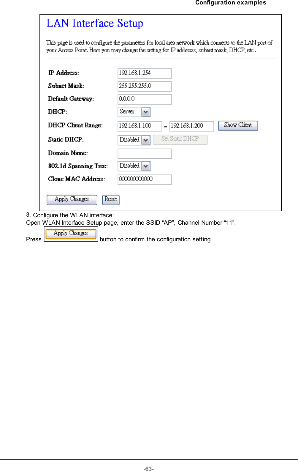
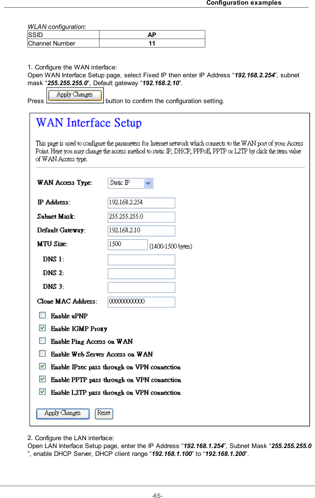
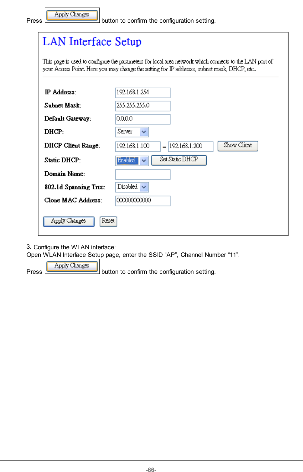
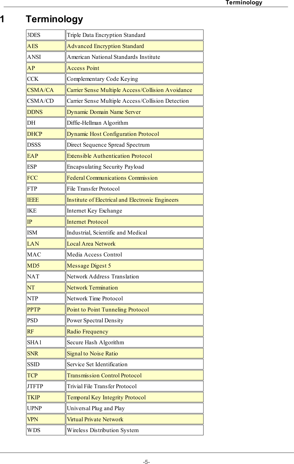
![Software configuration-29-4.3.11 LAN Interface SetupThis page is used to configure the parameters for local area network that connects to the LAN portsof your WLAN Broadband Router. Here you may change the setting for IP address, subnet mask,DHCP, etc.ItemDescriptionIP AddressFill in the IP address of LAN interfaces of this WLANAccess Point. Subnet MaskFill in the subnet mask of LAN interfaces of this WLANAccess Point.Default GatewayFill in the default gateway for LAN interfaces out goingdata packets.DHCPClick to select Disabled, Client or Server in differentoperation mode of wireless Access Point. DHCP Client RangeFill in the start IP address and end IP address to allocatea range of IP addresses; client with DHCP function setwill be assigned an IP address from the range.Show ClientClick to open the Active DHCP Client Table window thatshows the active clients with their assigned IP address,MAC address and time expired information. [Servermode only]](https://usermanual.wiki/Loopcomm-Technology/LP-8696C/User-Guide-1386951-Page-29.png)
![-30-Static DHCPSelect enable or disable the Static DHCP function frompull-down menu. [Server mode only]Set Static DHCPManual setup Static DHCP IP address for specific MACaddress. [Server mode only]Domain NameAssign Domain Name and dispatch to DHCP clients. It isoptional field.802.1d Spanning TreeSelect enable or disable the IEEE 802.1d Spanning Treefunction from pull-down menu.Clone MAC AddressFill in the MAC address that is the MAC address to beclonedApply ChangesClick the Apply Changes button to complete the newconfiguration setting.ResetClick the Reset button to abort change and recover theprevious configuration setting.4.3.11.1 Static DHCP SetupItemDescriptionIP AddressIf you select the Set Static DHCP on LAN interface, fill inthe IP address for it.MAC AddressIf you select the Set Static DHCP on LAN interface, fill inthe MAC address for it.CommentFill in the comment tag for the registered Static DHCP.Apply ChangesClick the Apply Changes button to complete the newconfiguration setting.](https://usermanual.wiki/Loopcomm-Technology/LP-8696C/User-Guide-1386951-Page-30.png)