Loopcomm Technology LP-9287C High Power 802.11g Wireless USB Adapter User Manual
Loopcomm Technology,.Inc. High Power 802.11g Wireless USB Adapter Users Manual
UserManual.wiki
>
Loopcomm Technology
>
LP 9287C User Manual
Users Manual
Navigation menu
Upload a User Manual
Namespaces
Wiki Guide
HTML
PDF
Info
Views
User Manual
Discussion / Help
Navigation
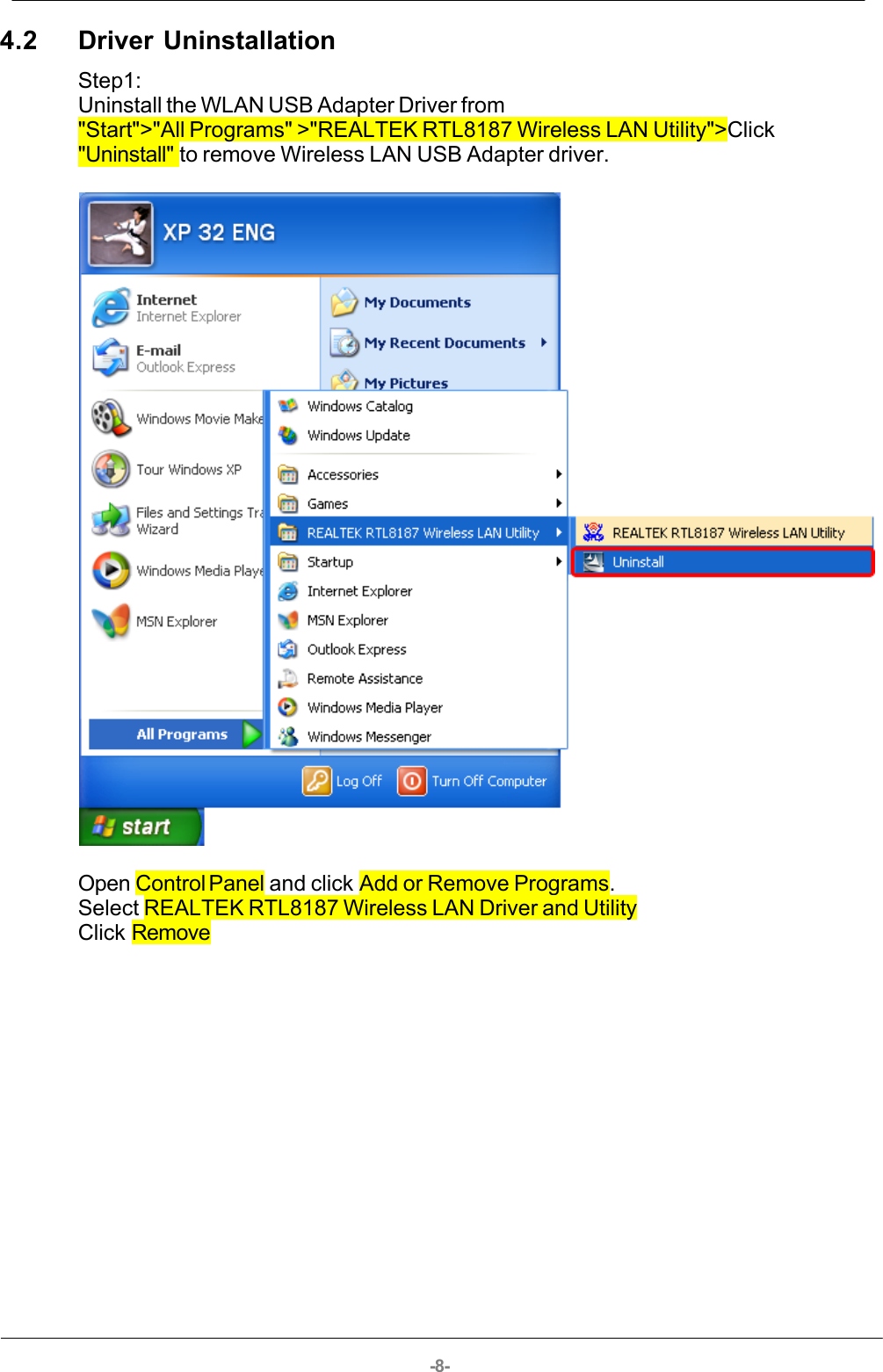
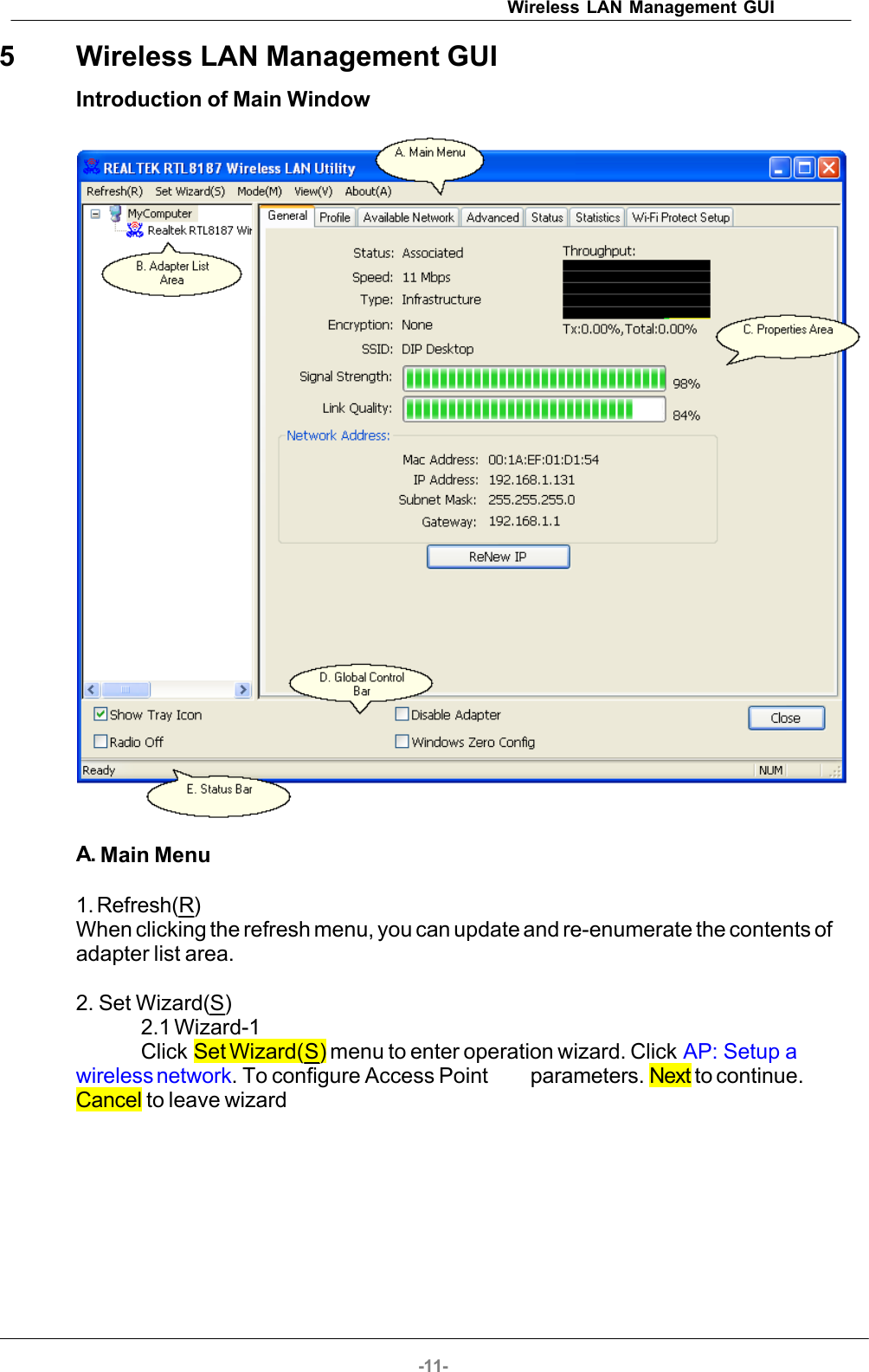
. Usermay skip wireless security. Strongly recommend user to setup wireless security to avoid invalid users. Back to go previous.Next to continue. Cancel to close wizard.](https://usermanual.wiki/Loopcomm-Technology/LP-9287C/User-Guide-1231099-Page-12.png)
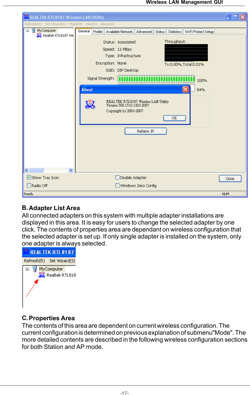
![-16-2.7 Wizard-7 Show all settings under AP mode. Click Finish to complete wizard setup.3. Mode(M)Wireless configuration is quickly switched to be either [Station] or [Access Point].4. View (V)Enable/disable the presence of E. Status Bar. Without the check mark (v) the E.Status Bar will be hidden.5. About (A)Click the "About" to show the about dialog. The application version and licenseinformation are shown in the about dialog.](https://usermanual.wiki/Loopcomm-Technology/LP-9287C/User-Guide-1231099-Page-16.png)