Loopcomm Technology LP2396K Outdoor 2.4GHz Wireless AP/CPE/Bridge User Manual
Loopcomm Technology,.Inc. Outdoor 2.4GHz Wireless AP/CPE/Bridge Users Manual
Users Manual

1
LP-2396K
Outdoor 2.4GHz Wireless AP/CPE/Bridge
User Manual

2
Table of Contents
1. Introduction ......................................................................................................................................... 3
1.1 Product Introduction ................................................................................................................ 4
1.2 Package Content ..................................................................................................................... 5
1.3 Product Features ..................................................................................................................... 6
1.4 Application ............................................................................................................................... 6
1.4.1 Wireless ISP (WISP) Mode .......................................................................................... 6
1.4.2 Bridge Mode ................................................................................................................. 7
1.5 Product Outline Introduction .................................................................................................... 8
1.5.1 Front view ..................................................................................................................... 8
1.5.2 Back view ..................................................................................................................... 8
1.5.3 LED Indication .............................................................................................................. 9
1.5.4 I/O Interface ................................................................................................................ 10
1.5.5 Mounting Options ....................................................................................................... 11
2. Hardware Installation ....................................................................................................................... 12
2.1 Connection overview ............................................................................................................. 12
2.2 Installation Steps ................................................................................................................... 12
2.3 IP Surveillance ....................................................................................................................... 14
3. Software Configuration .................................................................................................................... 15
3.1 System Requirements ........................................................................................................... 15
3.2 Easy Installation ..................................................................................................................... 15
3.3 Get started with LP-2396K .................................................................................................... 16
4. Software Features ............................................................................................................................ 17
4.1 Operation Mode ..................................................................................................................... 17
4.1.1 Access Point ............................................................................................................... 17
4.1.2 Client .......................................................................................................................... 25
4.1.3 WDS Access Point ..................................................................................................... 33
4.1.4 WDS Client ................................................................................................................. 41
4.1.5 AP Router ................................................................................................................... 49
4.1.6 Wireless ISP ............................................................................................................... 64
4.2 System Configuration ............................................................................................................ 80
4.2.1 Device IP Settings ...................................................................................................... 80
4.2.2 Time Settings .............................................................................................................. 81
4.2.3 Password Settings...................................................................................................... 82
4.2.4 System Management ................................................................................................. 83
4.2.5 Ping Watchdog ........................................................................................................... 84
4.2.6 Firmware Upgrade...................................................................................................... 85
4.2.7 Save and Restore ....................................................................................................... 85
4.2.8 Factory Default ........................................................................................................... 86
4.2.9 Reboot ........................................................................................................................ 86
4.2.10 Schedule Reboot ...................................................................................................... 87
4.3 Tools ....................................................................................................................................... 88
4.3.1 Network Ping .............................................................................................................. 88
4.3.2 Network Traceroute .................................................................................................... 89
4.4 Device Status ......................................................................................................................... 90
4.4.1 Device Information ..................................................................................................... 90
4.4.2 Wireless Information................................................................................................... 91
4.4.3 LAN Information ......................................................................................................... 91
4.4.4 Internet Information .................................................................................................... 92
4.4.5 Wireless Client Table .................................................................................................. 92
4.4.6 System LOG ............................................................................................................... 93
5.Compliance ....................................................................................................................................... 94

3
1. Introduction
Thank you for purchasing Loopcomm product. At loopcomm we strive to provide you with the
highest quality products through innovation and advanced technology. We pride ourselves on
delivering products that outperform the competition and go beyond your expectations. If you
have any questions please feel free to contact us. We’d love to hear from you and thank you for
your support!
Email: support@loopcomm.com
Website: www.loopcomm.com
Notice
This document is issued to guide users how to install and operate LP-2396K Outdoor
2.4Ghz Wireless AP/CPE/Bridge. Please read the document carefully to avoid any damage
which is caused by inappropriate use excluding from the warranty.
Loopcomm Technology Inc. reserves the right to revise/update the content of LP-2396K
user manual without advance notice.

4
1.1 Product Introduction
Loopcomm LP-2396K is an Outdoor 2.4Ghz Wireless AP/CPE/Bridge that provides wide
coverage of network connection in existing environment. It can operate up to 300Mbps data
rate by supporting IEEE 802.11b/g/n standard and with full WEP, WPA/WPA2 data security,
Wireless LAN Access Control List and TKIP/AES encryption, It keeps the data transmission safe
in any network connection mode. Moreover, it supports different operation modes for any
user’s applications like point to point network and IP surveillance.
Product Outline
5
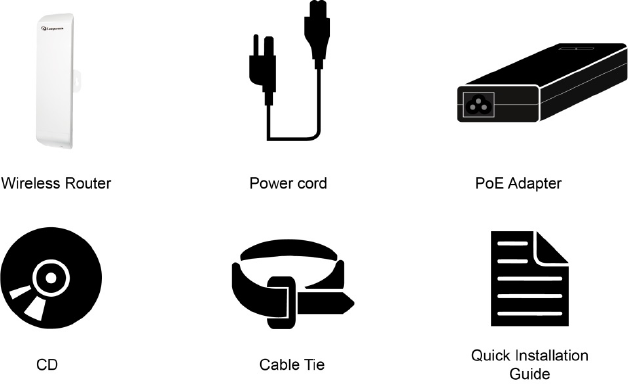
1.2 Package Content
The package content includes the following items, shown from left to right in the below figure.
LP-2396K
DC 24V/1A Power adapter
Power cord
User Manual CD
Cable Tie
Quick Installation Guide (QIG)
6
1.3 Product Features
Wireless Standards : IEEE 802.11b/g/n
Data transmission rate up to 300 Mbps at 40 MHz bandwidth
Operation Mode: Access Point/Client/WDS Access Point/WDS Client/AP Router/Wireless ISP
Reliable data security including WEP, WPA/WPA2, WPA-PSK/RADIUS, and WPA2-PSK/RADIUS
with TKIP/AES encryption.
Support SNMP V2 management, SSH, NTP, and Telnet.
Support QoS bandwidth control
MAC Access Control
Built-in Web-based management and firmware upgrade
PoE pass through available on Secondary Ethernet port (Configurable via Web UI)
Remotely enable system reset by PoE Adapter.
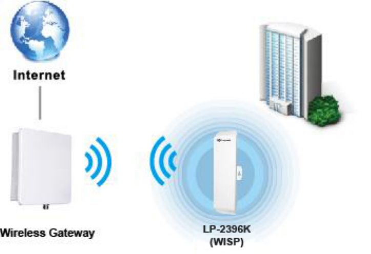
1.4 Application
1.4.1 Wireless ISP (WISP) Mode
LP-2396K can operate as station (client) in WISP mode to remotely receive broadband signal
from WISP outdoor AP (base station) of Internet Service Provider (ISP).
7
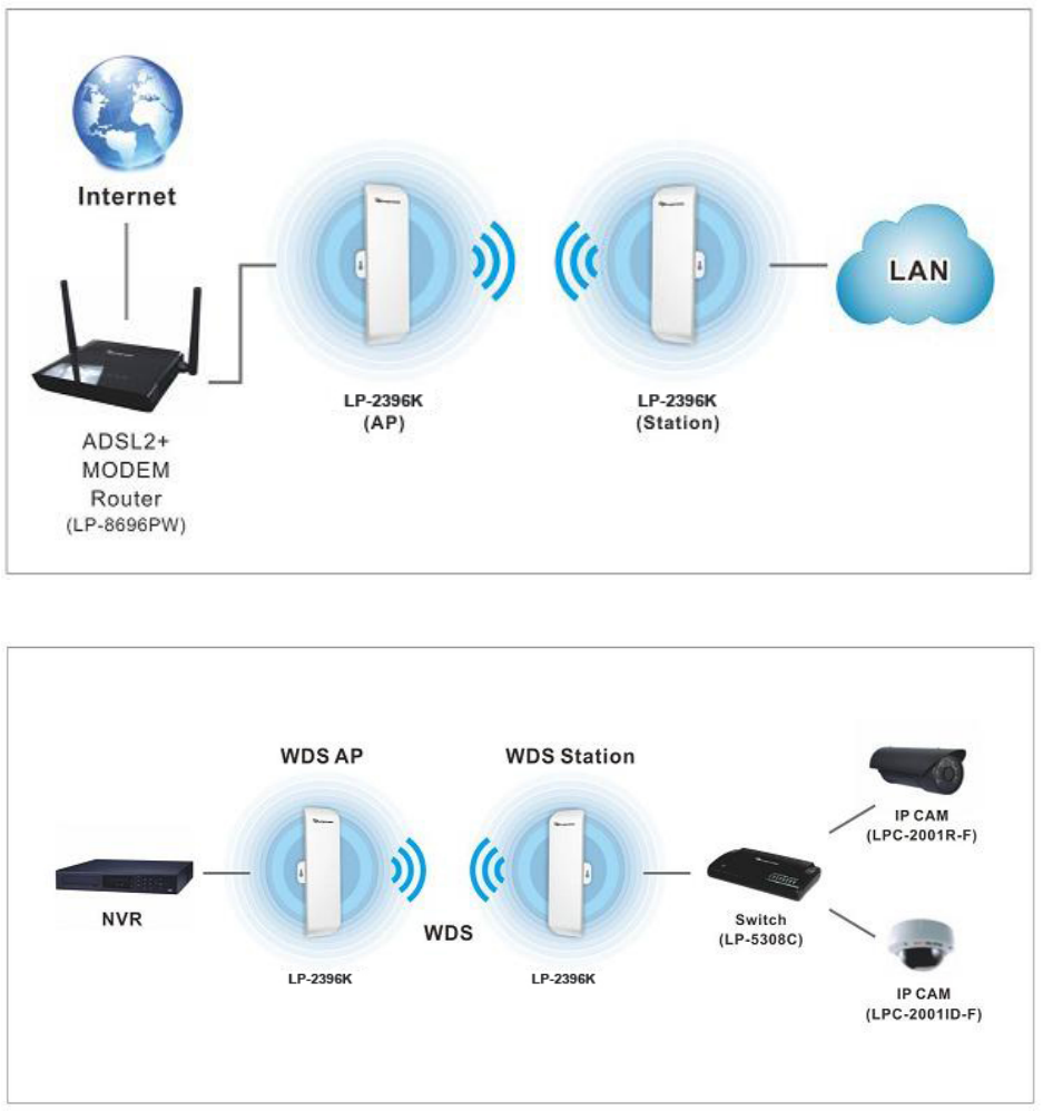
1.4.2 Bridge Mode
Since the antenna characteristics for LP-2396K is directional with high gain design, it can
transmit RF signal for several miles. Based on this point, LP-2396K is greatly used to bridge at
long distance transmission for point to point applications like IP surveillance, networking
company.
8
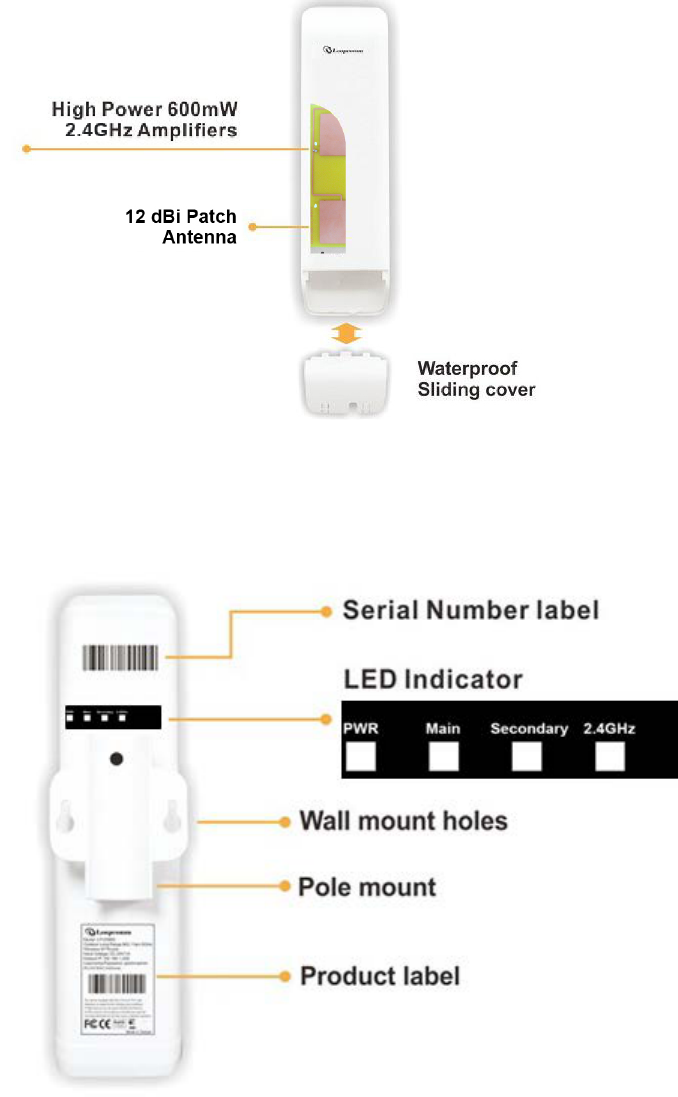
1.5 Product Outline Introduction
1.5.1 Front view
1.5.2 Back view
9
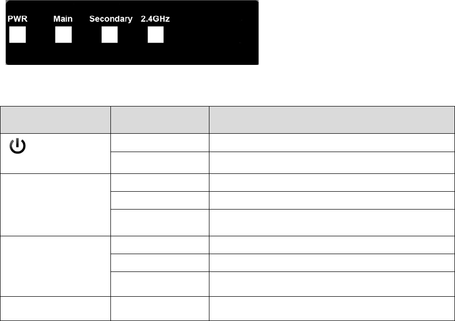
1.5.3 LED Indication
LED Indicator Status Description
ON The LP-2396K is powered ON.
OFF The LP-2396K is powered OFF.
Main ON Port linked.
OFF No connection.
Blink Data is being transmitted or received on the Main
Ethernet port.
Secondary ON Port linked.
OFF No connection.
Blink Data is being transmitted or received on the Secondary
Ethernet port.
2.4GHz Blink Data is being transmitted or received using Wi-Fi.
10
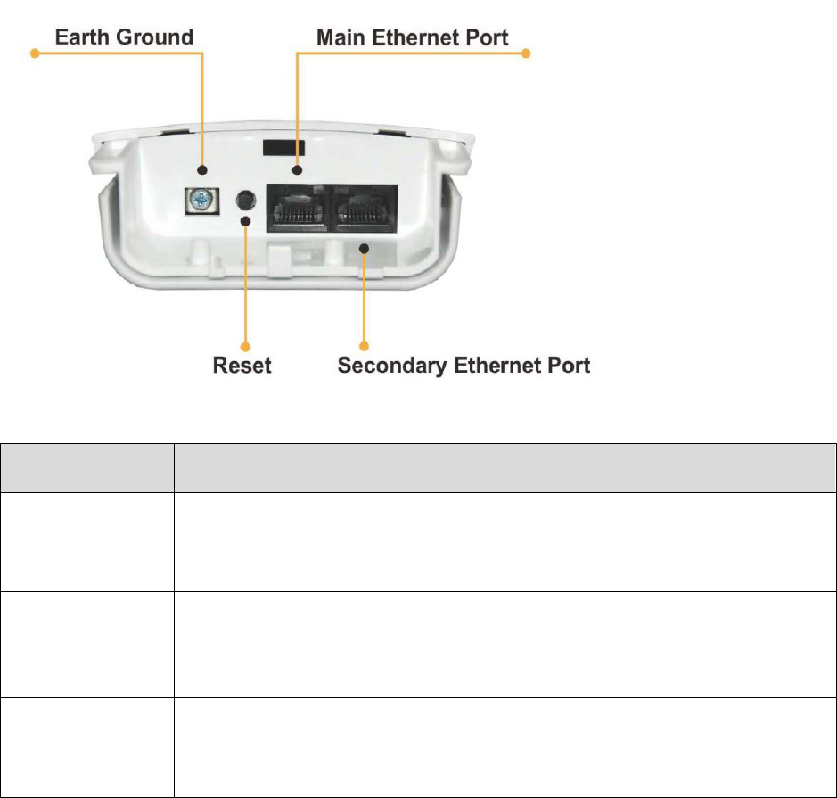
1.5.4 I/O Interface
Item
Description
Main
It mainly used as Power over Ethernet (PoE) port, which allows the router powered up
by PoE adapter when the connection is established by RJ-45 Cat.5 cable. It supports
auto-sensing on 10/100M speed, half/ full duplex, and complies with IEEE 802.3/ 802.3u
respectively.
Secondary
The Secondary Ethernet port allows users to connect to another device through RJ-45
Cat.5 cable. It supports auto-sensing on 10/100M speed, half/ full duplex, and complies
with IEEE 802.3/ 802.3u respectively.
(Note: In Operation mode the AP router’s secondary port will be WAN Port by default).
Reset Button
Press continually the reset button at least 5 seconds to reset the configuration
parameters to factory defaults
Earth Ground It used to connect the metal line to ground in order to avoid the device from external
electrical damage.
Note. LP-2396K built in PoE pass through function on Secondary Ethernet port. It means the
Secondary Ethernet port is able to provide 24V power for a secondary device if this function
enabled on Web Configuration (Please refer to the statement on Advanced Setting of Radio
menu).
11
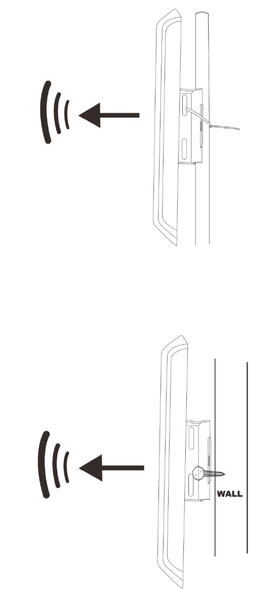
1.5.5 Mounting Options
Pole Mount
Use cable tie and make it pass through the one of middle holes to fix and tie on the pole.
Wall Mount
Please fix the screws into the wall and hang LP-2396K on the corresponding screws.
12
2. Hardware Installation
2.1 Connection overview
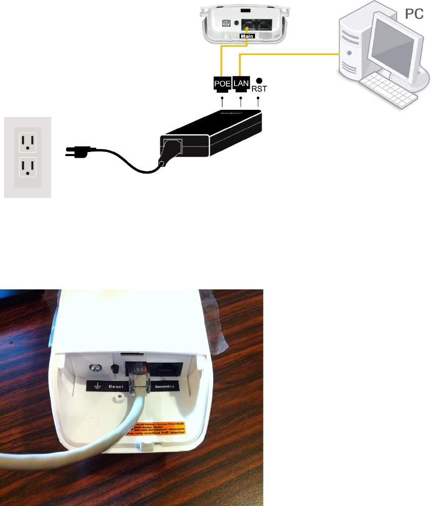
2.2 Installation Steps
1. Take off the water-proof sliding cover.
2. Connect the Main Ethernet port of LP-2396K with a RJ-45 cable.
Note. LP-2396K built in PoE pass through function on Secondary Ethernet port. It means the
Secondary Ethernet port is able to provide 24V power for a secondary device if this function
enabled on Web Configuration (Please refer to the statement on Advanced Setting of Radio
menu).
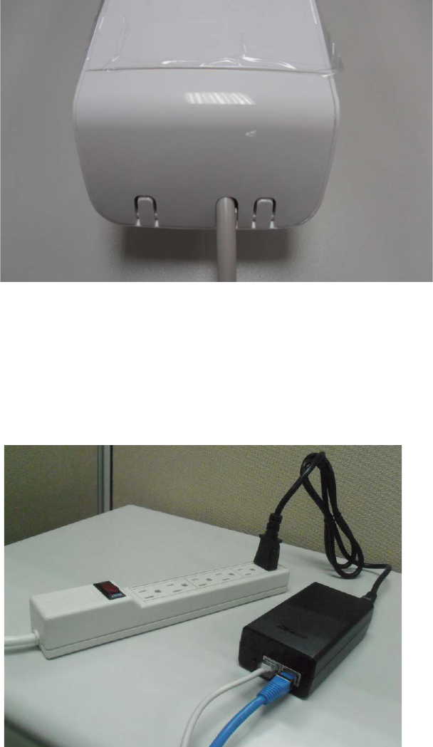
13
3. Make the water-proof sliding cover well installed.
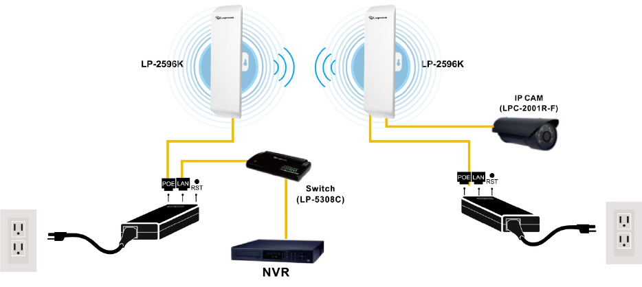
4. Connect Power cord to power outlet.
5. Connect other end of Power cord to PoE Adapter of 24V/1A.
6. PoE port: Connect other end of Main Ethernet port to PoE Adapter.
7. LAN port: Connect Ethernet cable from PoE Adapter to your computer/laptop for Web
configuration.
8. Reset button: It allows user to remotely reset the system of LP-2396K.
Note.
1. There is no software driver or utility installation needed.
2. RJ-45 8P8C Ethernet cable is required.
3. It takes about 60 seconds to complete the boot up sequence after LP-2396K powered up.
14
2.3 IP Surveillance
Example – Scenario for IP surveillance
The following figure indicates the basic setup to implement IP surveillance with a pair of LP-
2396K. The remote monitoring image can be delivered to local NVR via the high powered, long
distance transmission by LP-2396K.
15
3. Software Configuration
3.1 System Requirements
- Microsoft Windows XP/Vista/7/8, Mac iOS, Linux
- A Web Browser supports HTTP such as Internet Explorer, Google Chrome, Safari, and Mozilla
Firefox etc.
3.2 Easy Installation
Network Connection Setup:
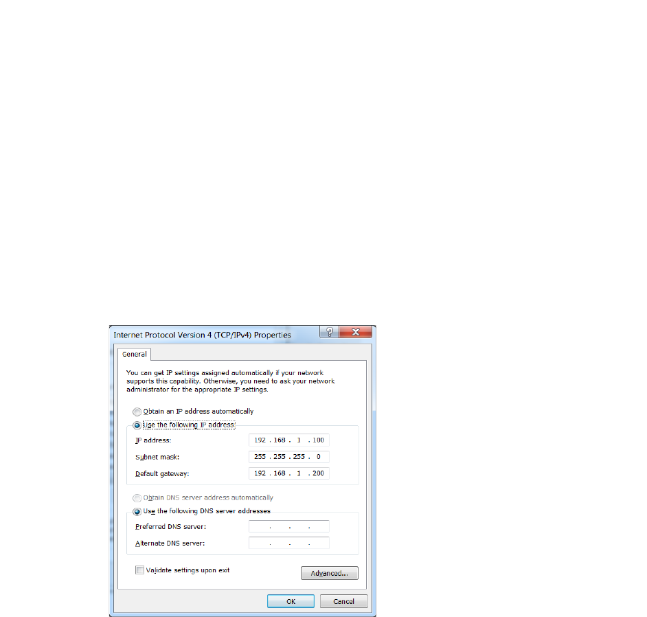
The default IP of LP-2396K is 192.168.1.200. You have to make sure your computer is on the
same network segment as LP-2396K before connecting to LP-2396K Configuration.
Example: In the Windows 7 operating system
1. Press Start and enter ncpa.cpl in search bar. You will see network connection page.
2. Select your network interface card and Right click to set Properties.
3. Double click Internet Protocol Version 4 (TCP/IPv4).
4. Select Specify an IP address and enter the IP address.
IP Address: 192.168.1.x (x can be any number between 1 to 254 except for 200)
Subnet Mask: 255.255.255.0
Default Gateway: 192.168.1.200
5. Click OK to complete the IP setting.
16
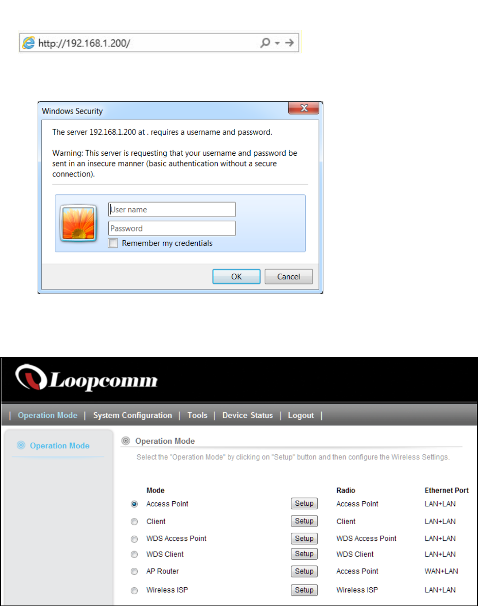
3.3 Get started with LP-2396K
1. Open Web browser and enter 192.168.1.200 in the URL field of Web browser.
2. Enter “admin” as default user name, and “admin” as default password.
After successful login , you can see the Loopcomm web page.
17
4. Software Features
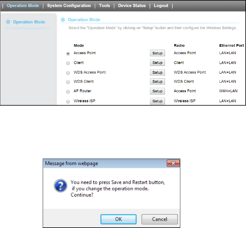
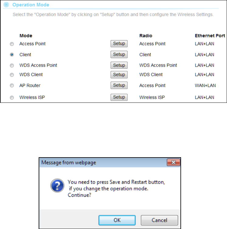
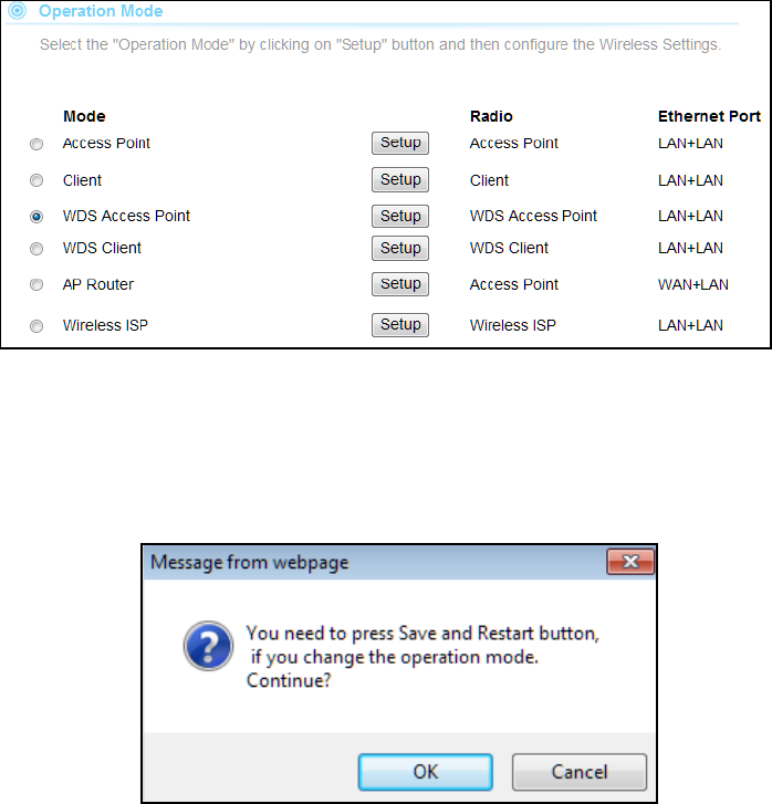
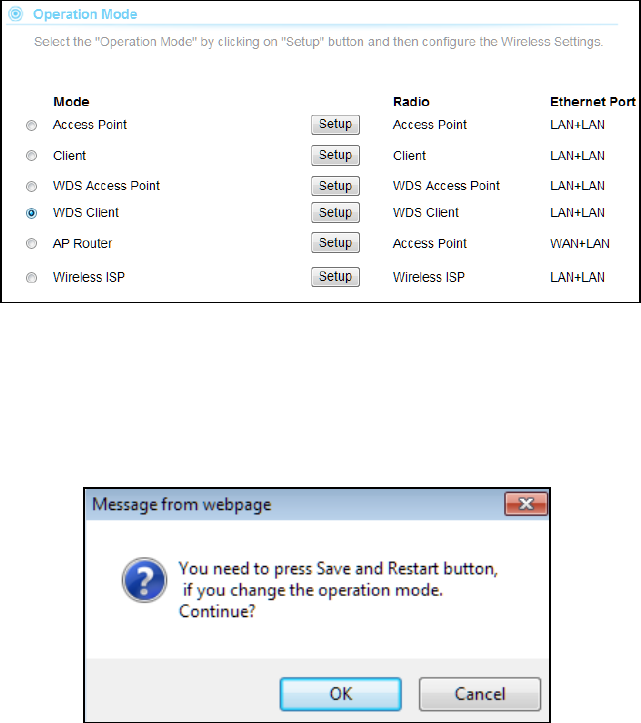
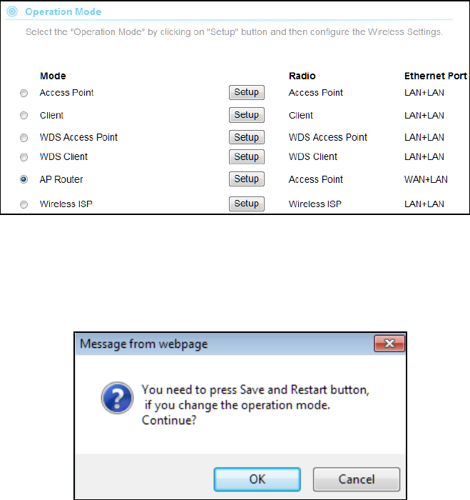
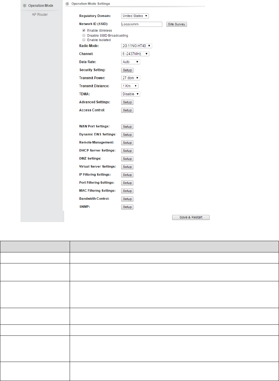
4.1 Operation Mode
In Operation Mode you will find wireless and WAN settings. The LP-2396K wireless settings are
dependent on the wireless operation mode you choose. To access wireless settings, click on the
“Setup” button. In Operation Mode there are 6 types, they are
4.1.1 Access Point
It Connects to an internal network (LAN) and broadcasts a wireless network connection
(WLAN). When operating in the Access Point mode, LP-2396K becomes the center hub of
the wireless network. All wireless cards and clients connect and communicate through the
device.
Note: Depending on the mode you choose, applicable settings will be enabled/ disabled
automatically.
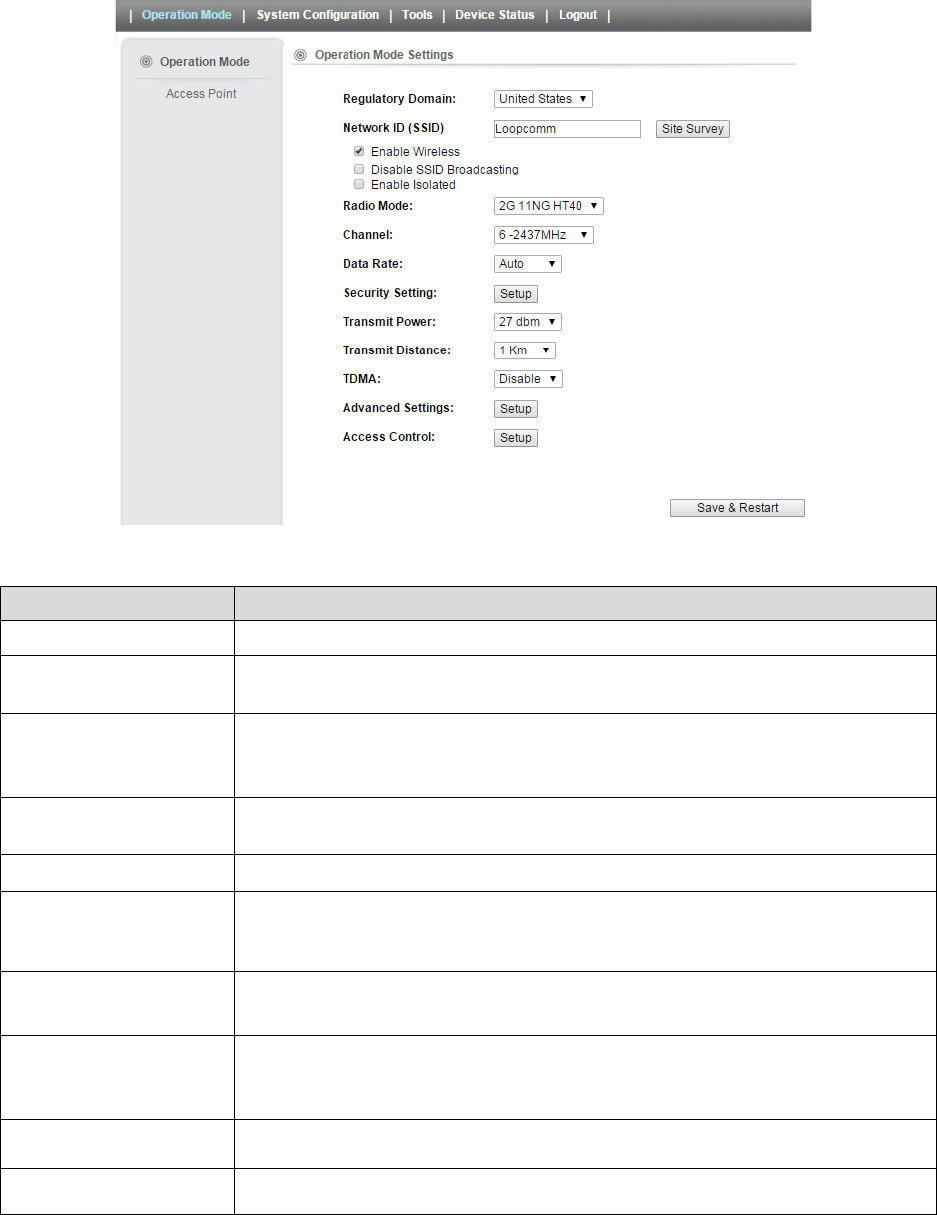
Press setup, then below Screen is displayed.
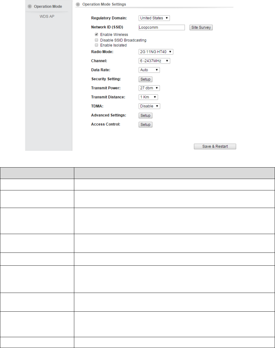
Press OK to continue, then below page is displayed.
18
Fields Description
Regulatory Domain Select the country from pull down menu.
Network SSID It is the wireless network name. User can use the default SSID or change it.
(Special characters cannot be used).
Enable Wireless
Disable SSID Broadcasting
Enable Isolated
Enable Wireless Option
SSID will be hidden, only users who know the SSID can associate with this network.
User cannot Ping.
Radio Mode
Select the Mode of 2G 11NG HT20 or 2G 11NG HT40
“Auto” option selects the mode by itself.
Channel Select the wireless communication frequency/channel from pull-down menu.
Data Rate Defines the data rate (in Mbps) at which the device should transmit wireless
packets. You can fix a specific data rate between MCS 0 and MCS 7 (or MCS 15 for
2x2 chain devices).
Transmit Power Defines the maximum average transmit output power (in dBm) of the device. The
transmit power level maximum is limited according to country regulations.
Transmit Distance Changing the distance value will change the ACK (Acknowledgement) timeout value
accordingly, so it means the distance should be set as real distance between LP-
2396K and other device for accurate transmission performance.
TDMA Time Division Multiple Access. Enable/Disable the function to access.
Save and Restart It saves the new settings and restarts.
19
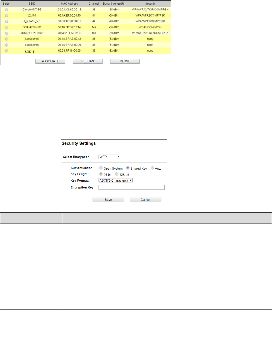
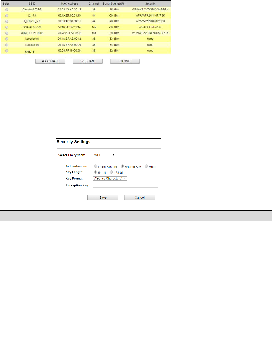
Site Survey
You could configure AP Client parameters here.
Click Rescan to browse more networks then select the SSID and press associate then close the page.
Note: Enter the SSID Password, if necessary.
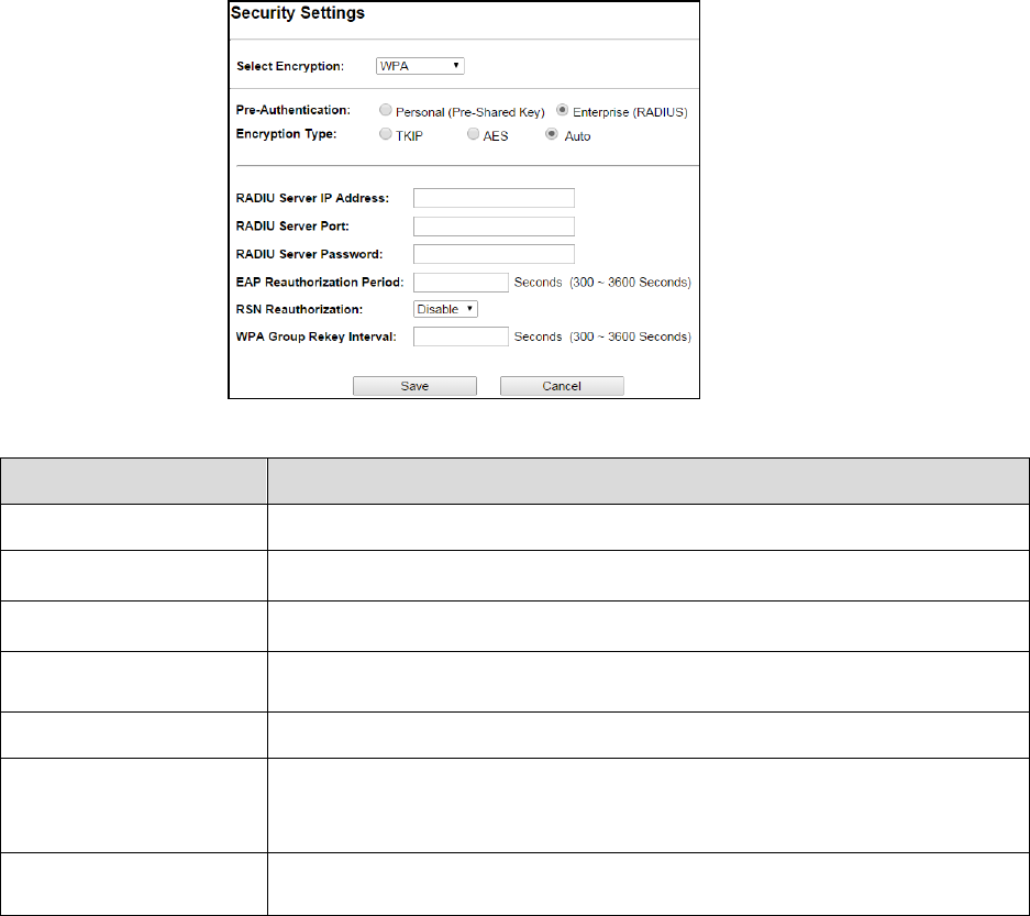
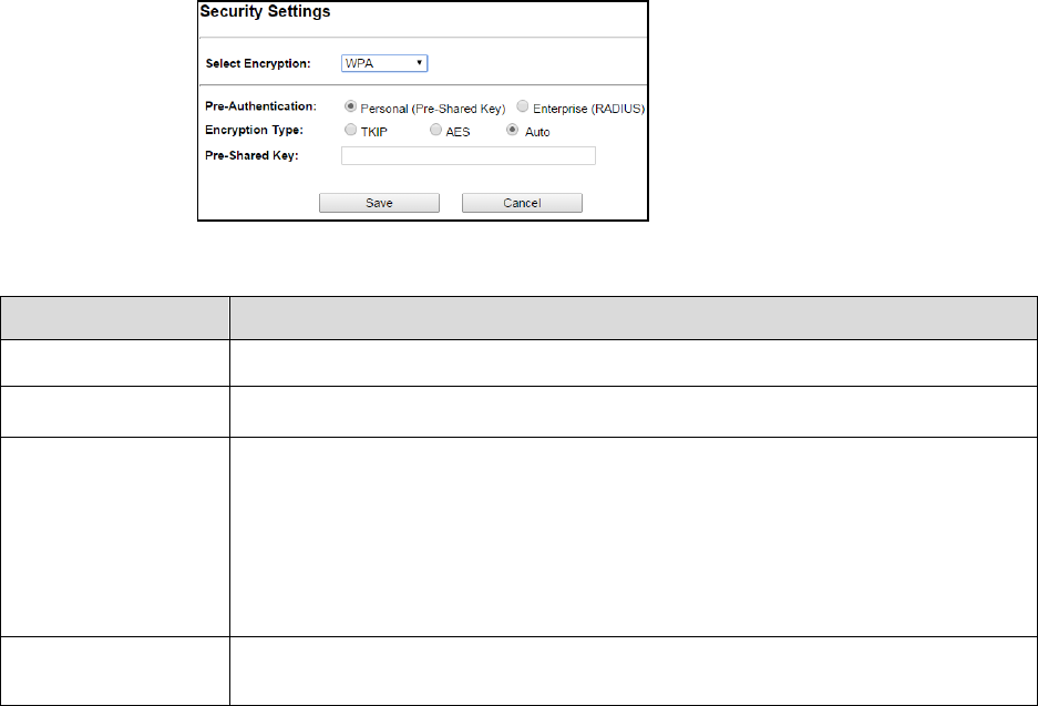
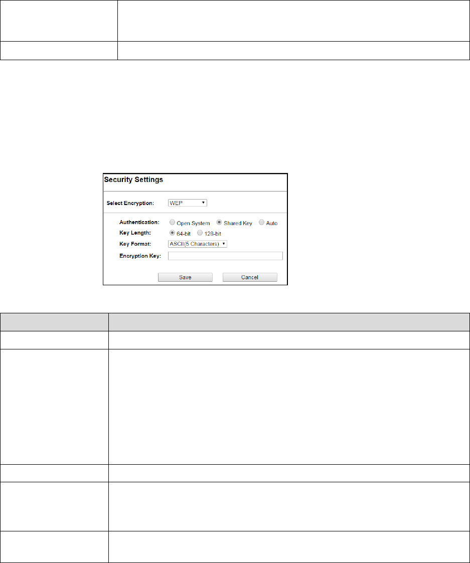
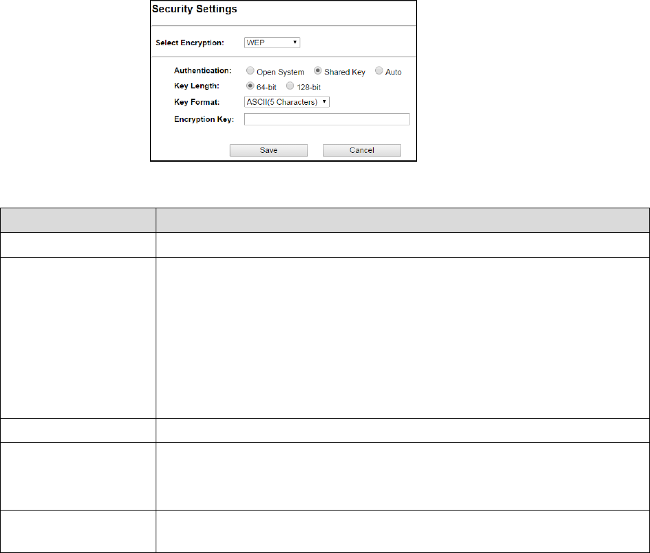
Security Settings
Security settings allow you to use encryption to secure your data.
There are 4 Encryption Modes in Security Settings. They are WEP, WPA, WPA2, and WPA-Mixed.
Functions are same for all Modes, below example is for WEP and WPA Encryption.
Fields Description
Select Encryption Select the Encryption Mode from the pull down menu.
Authentication
Open System:
Open system authentication provides identification for using the
wireless adapter's MAC address. Open system authentication is used when no
authentication is required.
Shared Key: It verifies that an authentication-initiating station has knowledge of a
shared secret. The 802.11 standard currently assumes that the shared secret is
delivered to the participating wireless clients by means of a more secure channel that
is independent of IEEE 802.11
Auto: Auto is the default authentication algorithm. It will change its authentication
type automatically to fulfill client’s requirement.
Key Length
Select the Key length
Key Format When Key Length is selected as 64-bites then Input ASCII (5 Characters) or Hex (10
Characters)
When Key Length is selected as 128-bits then Input ASCII (13 Characters) or Hex (128
Character)
Encryption Key
User can enter the characters based on selected Key Length & Key Format. The
format can be passphrase or characters.
20
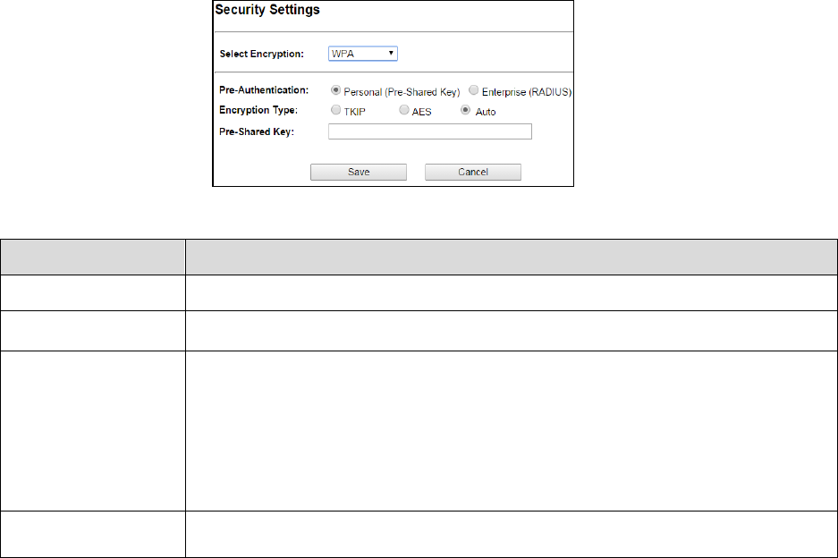
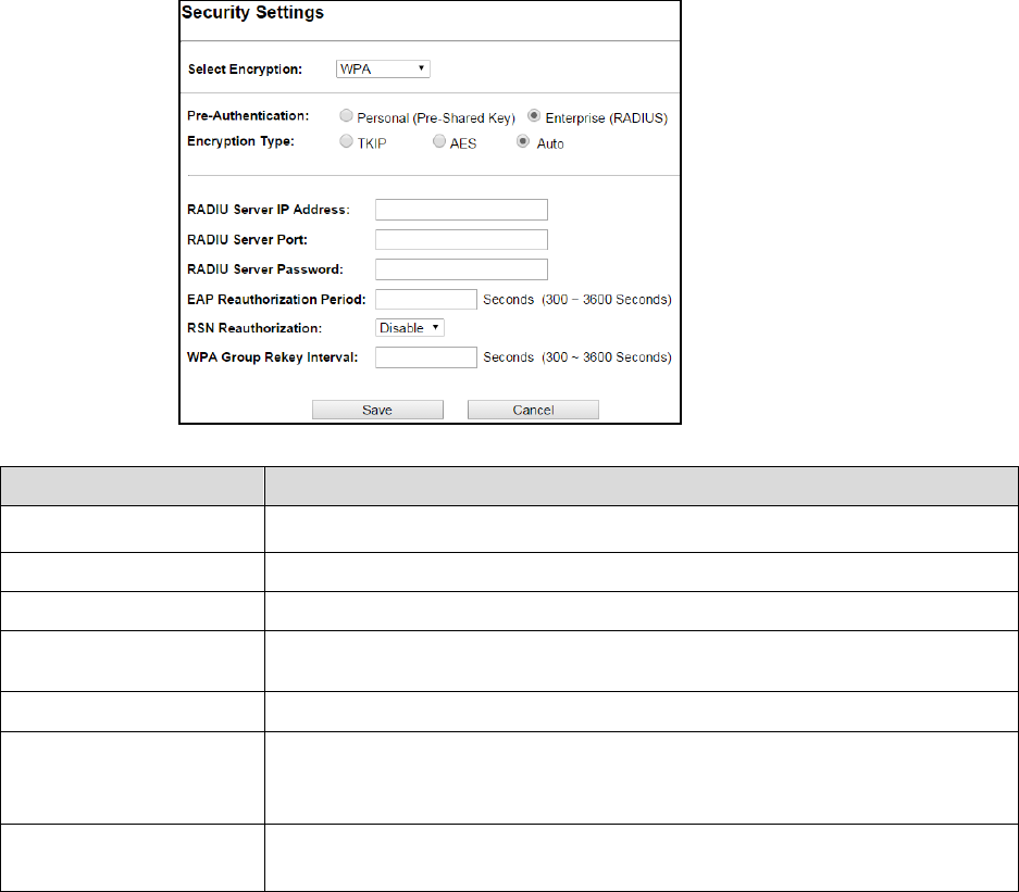
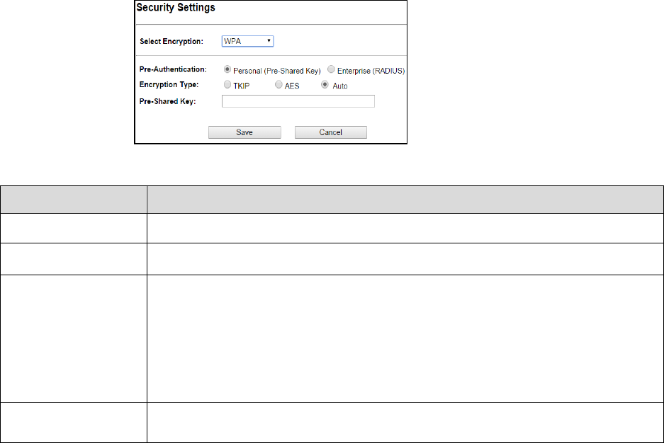
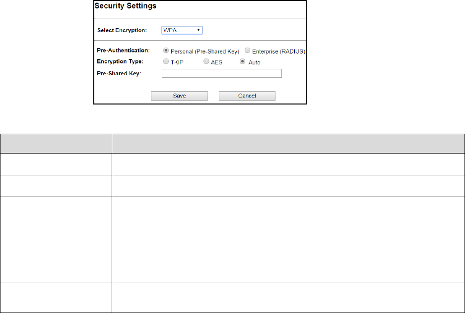
Fields Description
Select Encryption Select the Encryption Mode from the pull down menu.
Pre-Authentication Select Pre-Authentication as Personal or Enterprise.
Encryption Type
TKIP:
Temporal Key Integrity Protocol (TKIP) for data Encryption. TKIP utilizes a
stronger encryption method and incorporates Message Integrity Code (MIC) to provide
protection against hackers.
AES: Advanced Encryption Standard (AES) for data encryption. AES utilizes a symmetric
128-bit block data encryption.
AUTO: Auto is the default Encryption Type. It will change automatically to fulfill client’s
requirement.
Pre-shared Key User can enter Maximum number of Key Length. The format can be passphrase or any
characters.
21
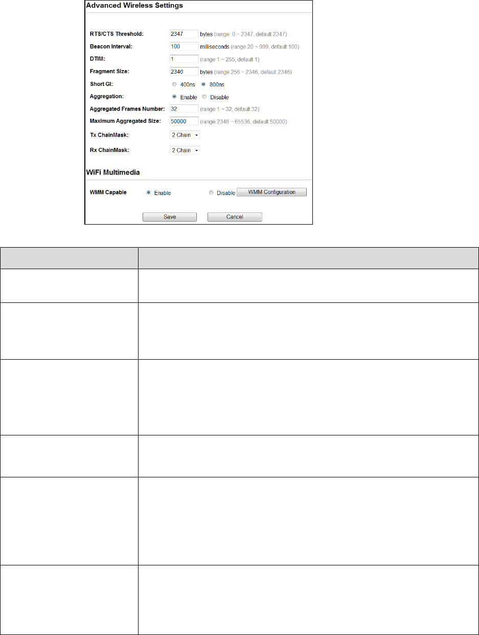
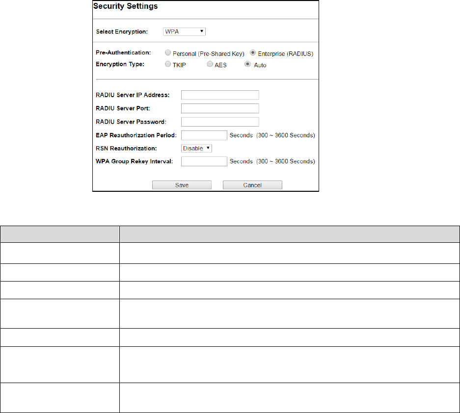
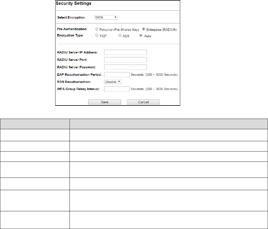
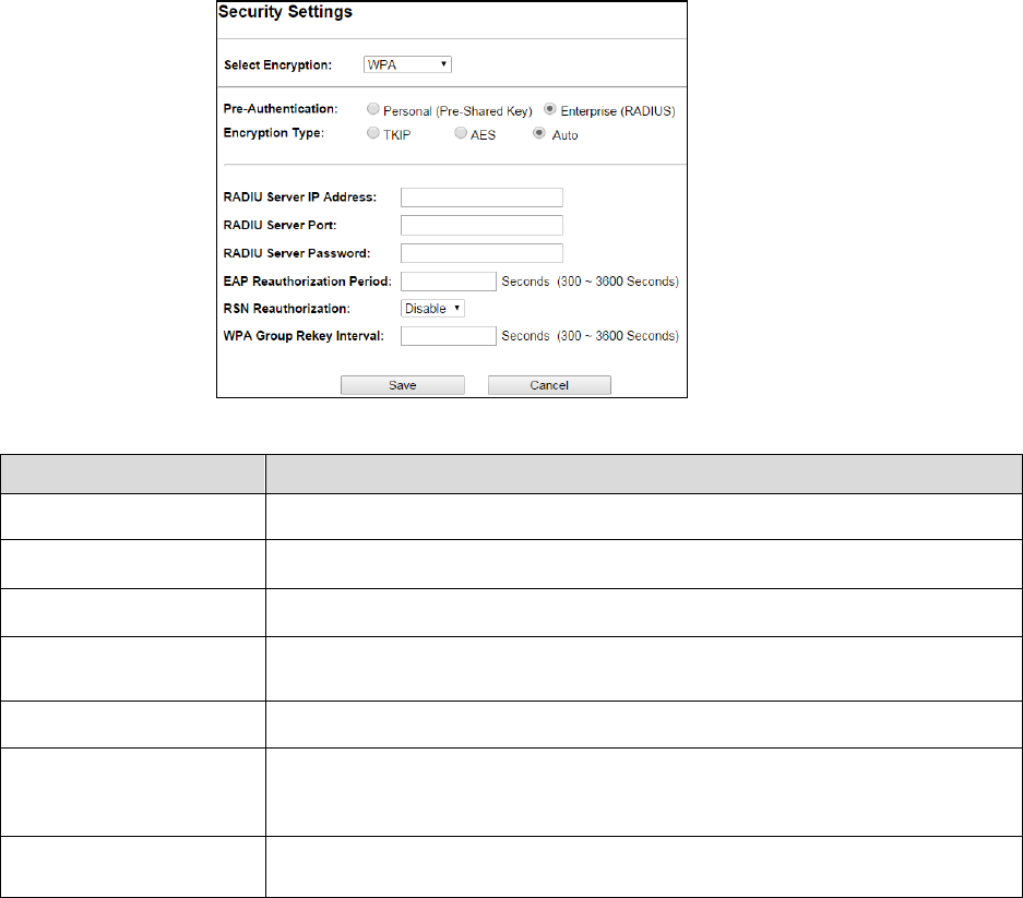
Fields Description
RADIU Server IP Address Enter the RADIU Server’s IP Address provided by your ISP.
RADIU Server Port
Enter the RADIUS Server’s port number provided by your ISP.
RADIU Server Password
Enter the RADIUS Server’s Password provided by your ISP.
EAP Reauthorization
Period
EAP- Session timeout interval for 802.1x re-authorization setting. Session timeout
interval unit is seconds
RSN Reauthorization Enable/Disable the function to access.
WPA Group Rekey Interval A group key is used for multicast/broadcast data, and the re-key interval is time
period that the system will change the group key periodically. The shorter the
interval is, the better the security.it varies from 300 to 3600 Seconds.
Save
Cancel
Click Save to change the new settings.
Click cancel to clear the entered settings.
22
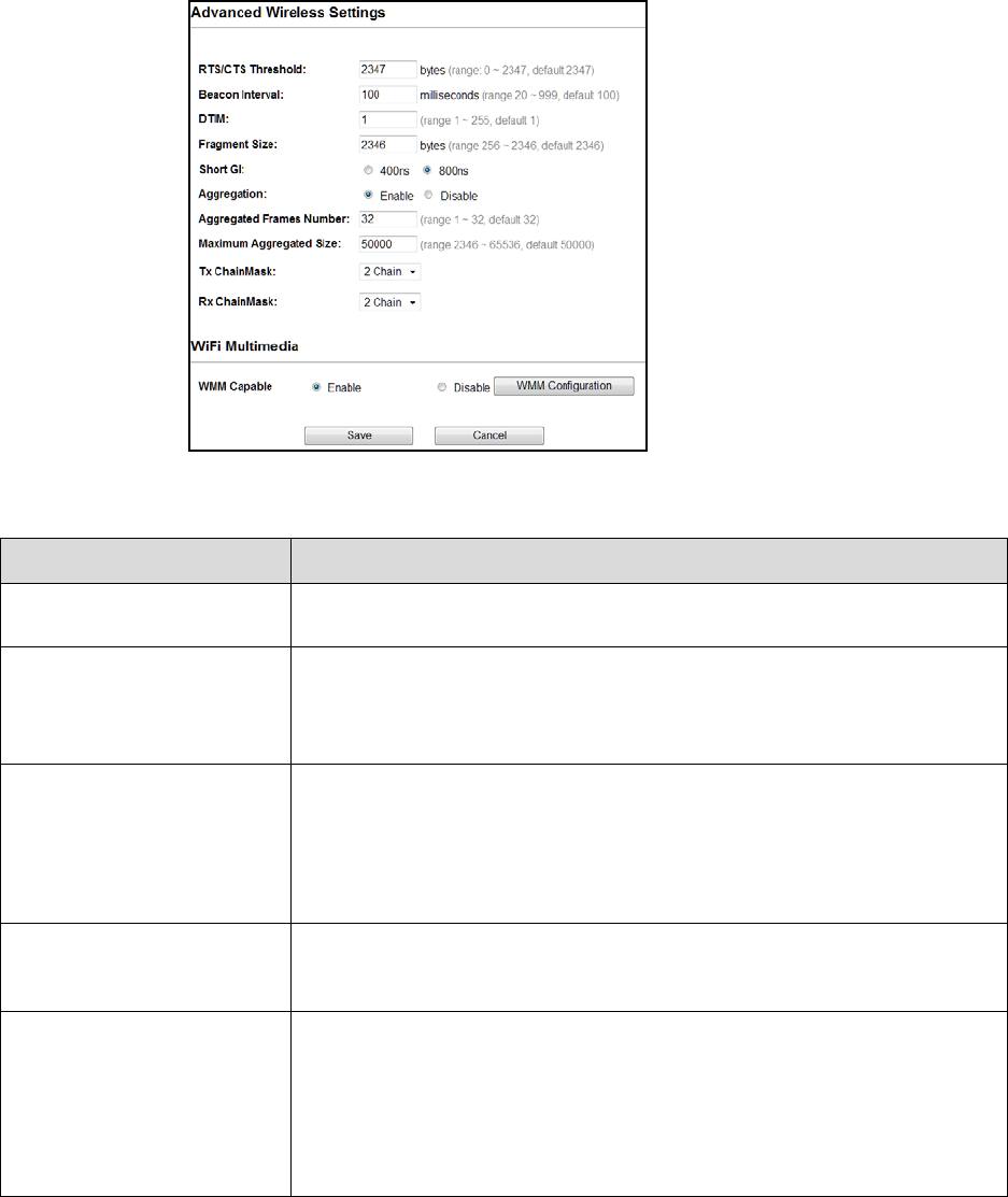
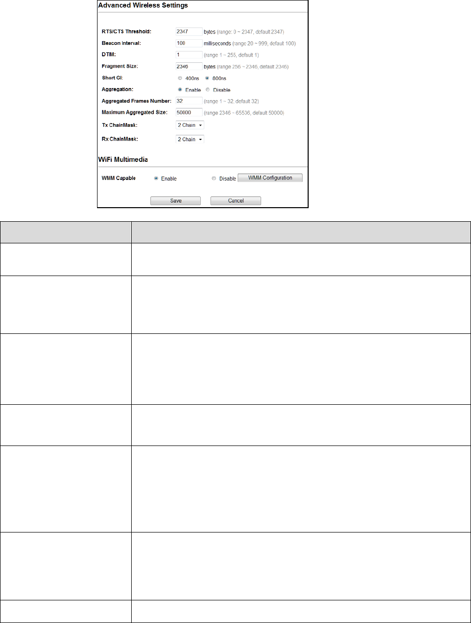
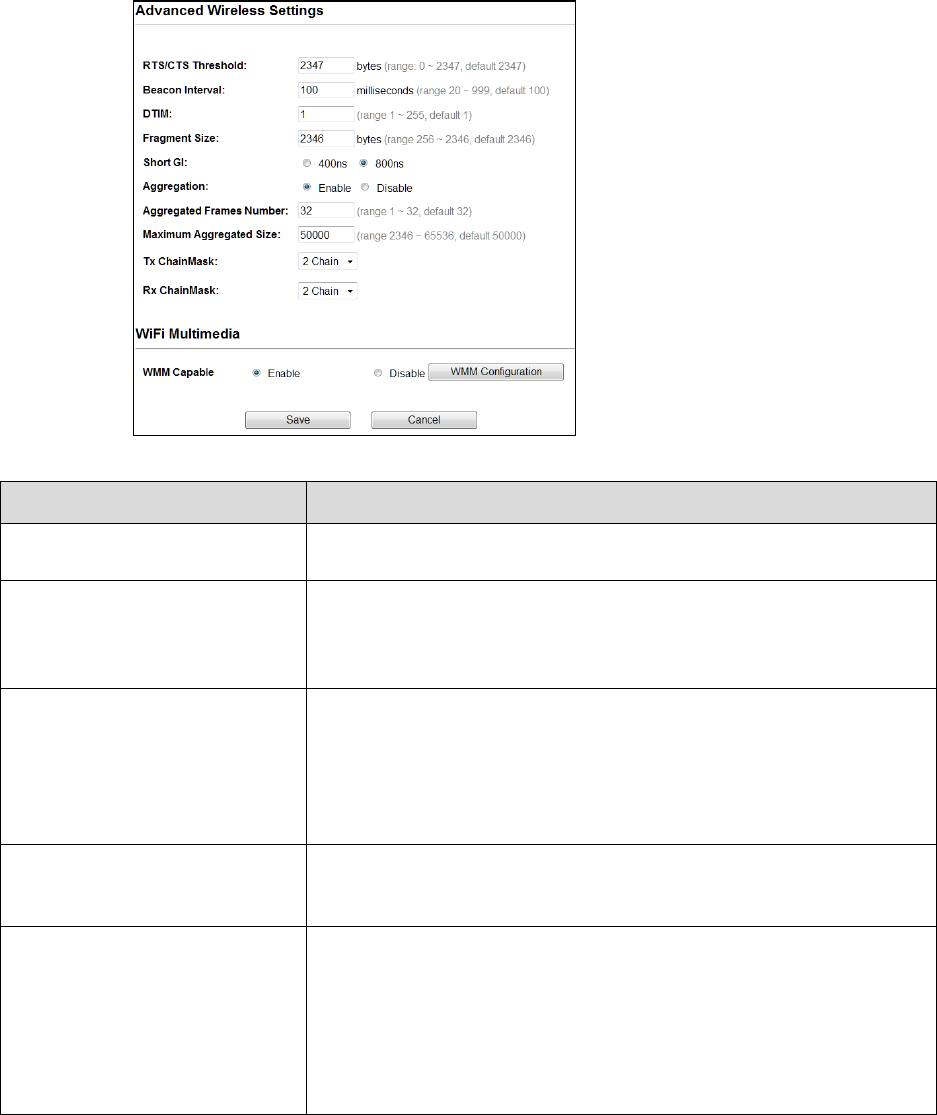
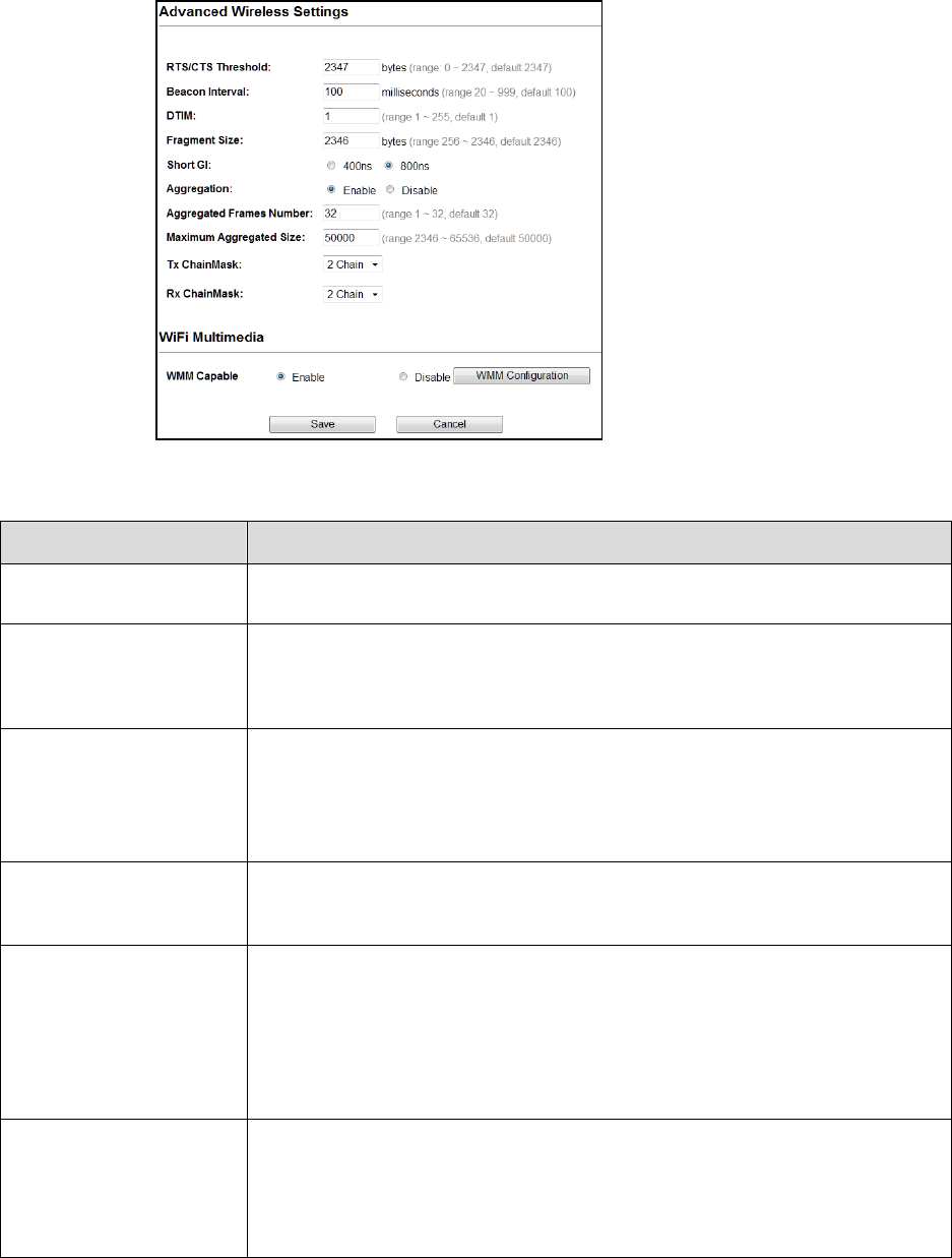
Advanced Settings
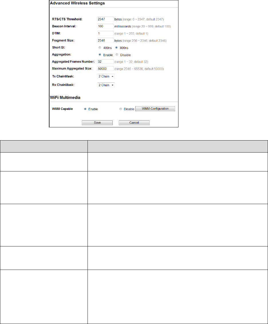
Fields Description
RTS/CTS Threshold
Determines the packet size of a transmission and, through the use of an AP,
helps control traffic flow. The range is 0-2347 bytes.
Beacon Interval Beacons are the packets sending by Access point to synchronize the wireless
network. The beacon interval is the time interval between beacons sending by
this unit in AP or AP+WDS operation. The default and recommended beacon
interval is 100 milliseconds.
DTIM This is the Delivery Traffic Indication Map. It is used to alert the clients that
multicast and broadcast packets buffered at the AP will be transmitted
immediately after the transmission of this beacon frame. You can change the
value from 1 to 255. The AP will check the buffered data according to this
value. For example, selecting “1” means to check the buffered data at every
beacon.
Fragment Size A large data frame is fragmented into several fragments each of size equal to
fragment threshold. By tuning the fragment threshold value, we can get
varying fragment sizes.
Short GI (Guard Interval) A GI is a period of time between symbol transmission that allows reflections
(from multipath) from the previous data transmission to settle before
transmitting a new symbol. The 802.11n draft specifies two guard intervals:
400ns (short) and 800ns (long). Support of the 400ns GI is optional for transmit
and receive. The purpose of a guard interval is to introduce immunity to
propagation delays, echoes, and reflections to which digital data is normally
very sensitive.

23
Aggregation A part of the 802.11n standard that allows sending multiple frames per single
access to the medium by combining frames together into one larger frame. It
creates the larger frame by combining smaller frames with the same physical
source, destination end points, and traffic class (QoS) into one large frame with
a common MAC header
Aggregated Frames Number Determines the number of frames combined in the new larger frame.
Maximum Aggregated Size Determines the size (in bytes) of the larger frame.
Tx/Rx ChainMask
Displays the number of independent spatial data streams the device is
transmitting (TX) and receiving (RX) simultaneously within one spectral channel
of bandwidth. Multiple chains increase data transfer performance significantly.
WMM Capable
Wi-Fi Multimedia
Enable the feature to access
WMM Configuration Displays the WMM Parameters of station and Access Point
Save
Cancel
Save the changed settings
Cancel the selected settings
24
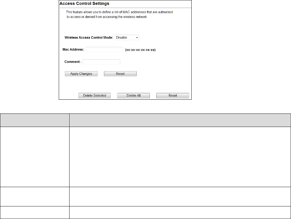
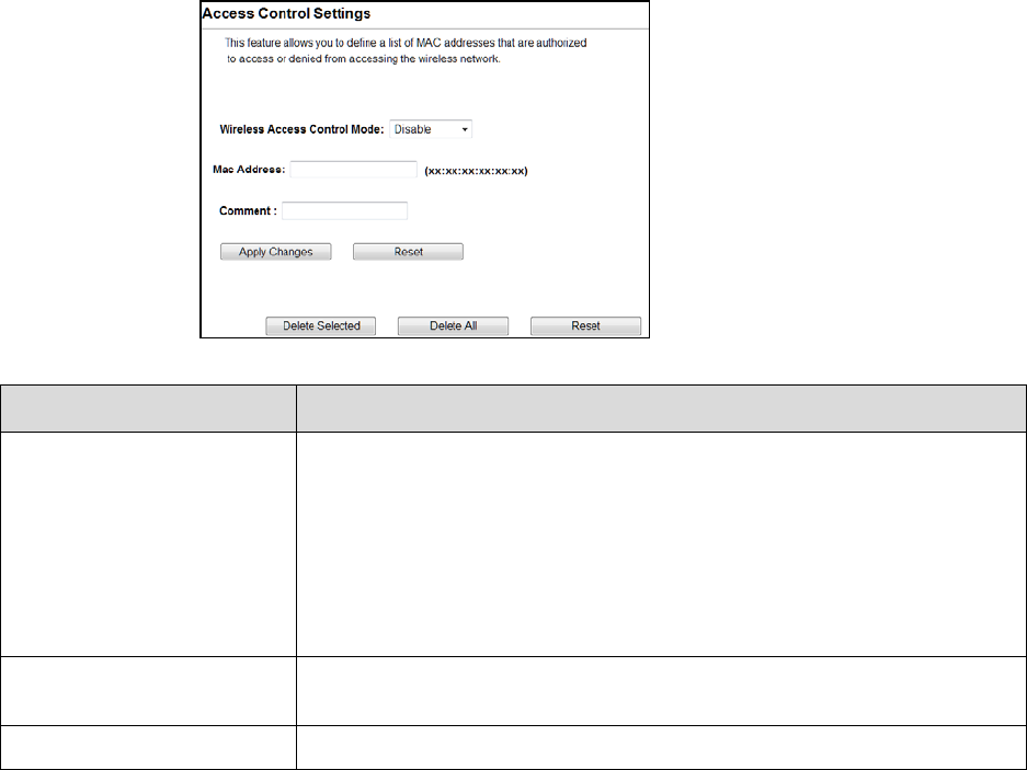
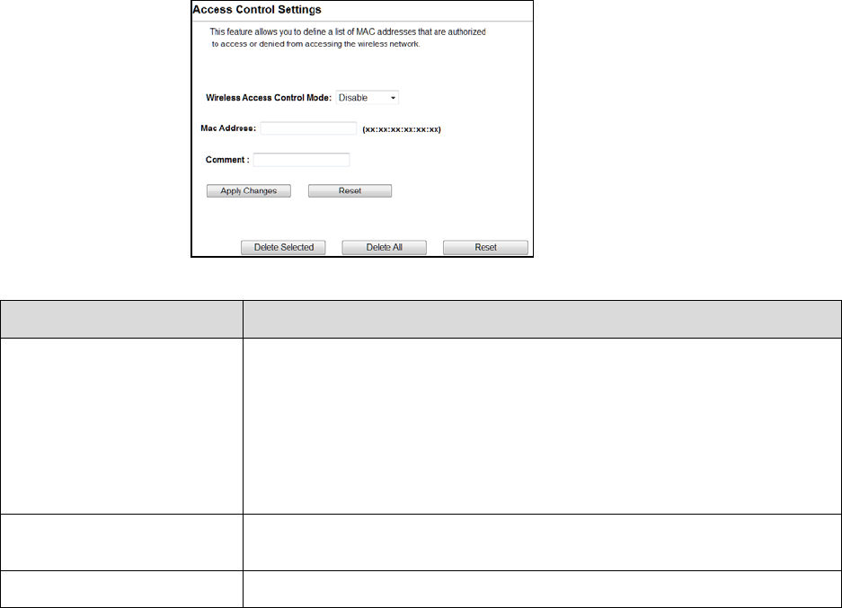
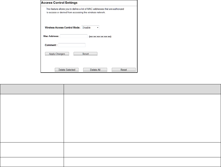
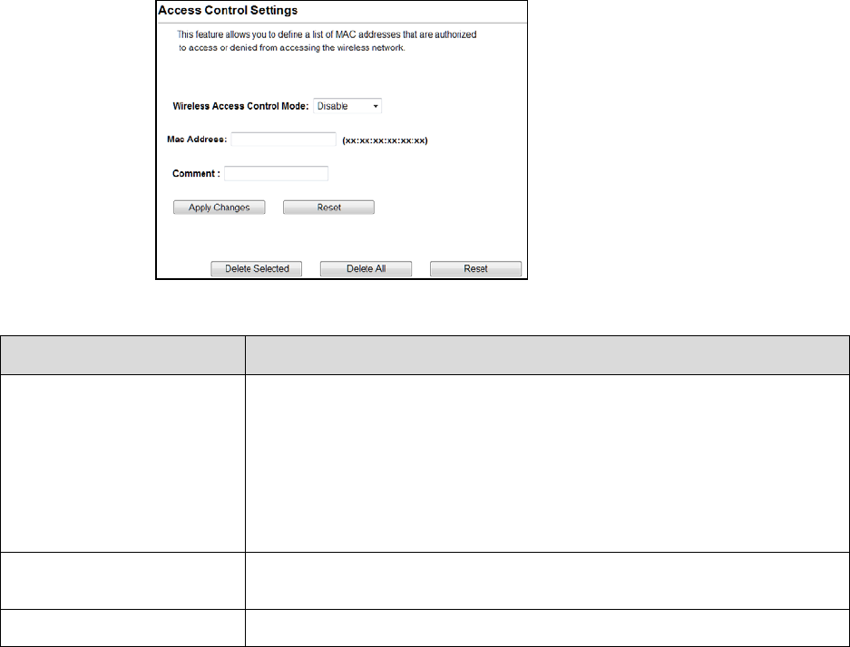
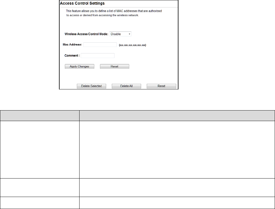
Access Control
This page allows administrator to have Access Control by entering MAC address of client
stations. When this function is Enabled, MAC address can be added into access control list and
only those clients whose wireless MAC address are in the access control list will be able to
connect or disconnect the internet.
Fields
Description
Wireless Access Control
Mode
The Selections are:
Disable: Disable the wireless ACL feature.
Allow Listed: When this option is selected, no wireless clients except those whose
MAC addresses are in the current access control list will be able to connect to
internet.
Deny Listed: When this option is selected, all wireless clients except those whose
MAC addresses are in the current access control list will not be able to connect to
internet.
Mac Address Enter client MAC address and press “Apply Changes” button to add client MAC
address into current access control list.
Comment Make a comment for Wireless access control.
Function buttons for the Access Control List:
Apply Changes
Click to add this entry into the Access Control List.
The Access Control List lists the client MAC addresses. Any wireless client with its MAC address
listed in this access control list will be able to connect to the device. You can select the entries
at the Select column and apply to the following function buttons.
Delete Selected: Delete the selected entries from the list.
Delete All: Flush the list.
Reset: Clear the settings.
25
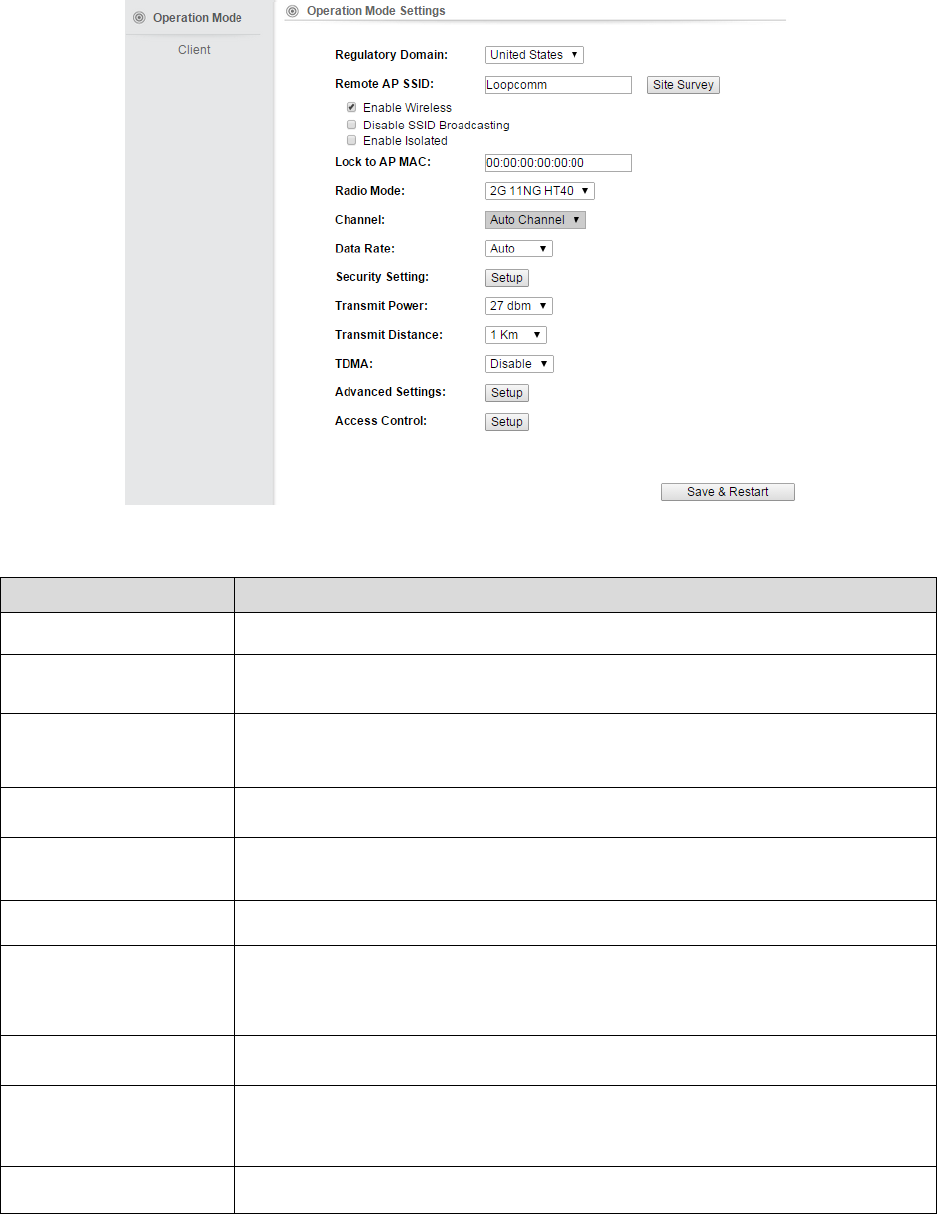
4.1.2 Client
It acts as a wireless client, to connect a remote segment to an existing WLAN
Note: Depending on the mode you choose, applicable settings will be enabled/disabled
automatically.
Press setup, then below Screen is displayed.
Press OK to continue, then below page is displayed.
26
Fields Description
Regulatory Domain Select the country from pull down menu.
Remote AP SSID Select Site Survey option then it will Scan & displays the SSID List, Choose one SSID
from the list.
Enable Wireless
Disable SSID Broadcasting
Enable Isolated
Enable Wireless Option
SSID will be hidden, only users who know the SSID can associate with this network.
User cannot Ping.
Lock to AP Mac Enter MAC address of the access point to which the client will be locked &
connected.
Radio Mode Select the Mode of 2G 11NG HT20 or 2G 11NG HT40
“Auto” option selects the mode by itself.
Channel Select the wireless communication frequency/channel from pull-down menu.
Data Rate Defines the data rate (in Mbps) at which the device should transmit wireless
packets. You can fix a specific data rate between MCS 0 and MCS 7 (or MCS 15 for
2x2 chain devices).
Transmit Power Defines the maximum average transmit output power (in dBm) of the device. The
transmit power level maximum is limited according to country regulations.
Transmit Distance
Changing the distance value will change the ACK (Acknowledgement) timeout value
accordingly, so it means the distance should be set as real distance between LP-
2396K and other device for accurate transmission performance.
Save and Restart It saves the new settings and restarts.
27
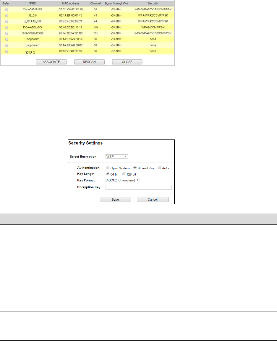
Site Survey
You could configure AP Client parameters here.
Click Rescan to browse more networks then select the SSID and press associate then close the page.
Note: Enter the SSID Password, if necessary.
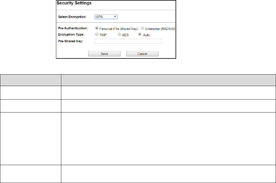
Security Settings
Security settings allow you to use encryption to secure your data.
There are 4 Encryption Modes in Security Settings. They are WEP, WPA, WPA2, and WPA-Mixed.
Functions are same for all Modes, below example is for WEP and WPA Encryption.
Fields
Description
Select Encryption
Select the Encryption Mode from the pull down menu.
Authentication
Open System: Open system authentication provides identification for using the
wireless adapter's MAC address. Open system authentication is used when no
authentication is required.
Shared Key: It verifies that an authentication-initiating station has knowledge of a
shared secret. The 802.11 standard currently assumes that the shared secret is
delivered to the participating wireless clients by means of a more secure channel that
is independent of IEEE 802.11
Auto: Auto is the default authentication algorithm. It will change its authentication
type automatically to fulfill client’s requirement.
Key Length Select the Key length
Key Format
When Key Length is selected as 64-bites then Input ASCII (5 Characters) or Hex (10
Characters)
When Key Length is selected as 128-bits then Input ASCII (13 Characters) or Hex (128
Character)
Encryption Key User can enter the characters based on selected Key Length & Key Format. The
format can be passphrase or characters.
28
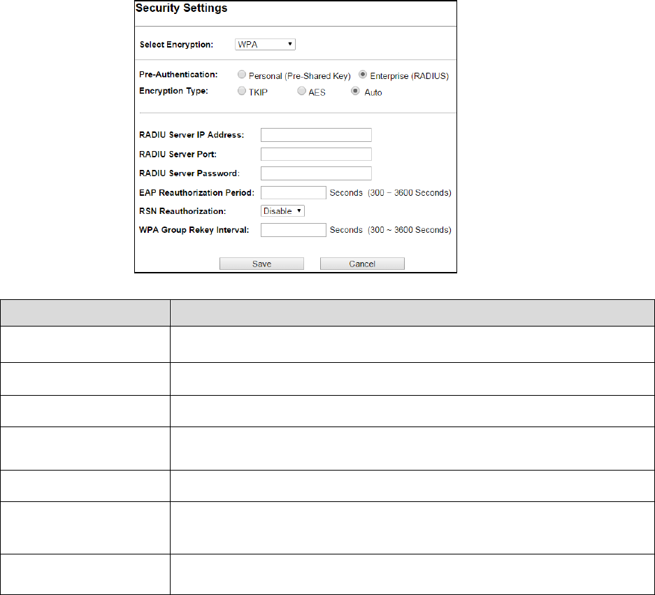
Fields Description
Select Encryption Select the Encryption Mode from the pull down menu.
Pre-Authentication Select Pre-Authentication as Personal or Enterprise.
Encryption Type TKIP: Temporal Key Integrity Protocol (TKIP) for data Encryption. TKIP utilizes a
stronger encryption method and incorporates Message Integrity Code (MIC) to provide
protection against hackers.
AES: Advanced Encryption Standard (AES) for data encryption. AES utilizes a symmetric
128-bit block data encryption.
AUTO: Auto is the default Encryption Type. It will change automatically to fulfill client’s
requirement.
Pre-shared Key
User can enter Maximum number of Key Length. The format can be passphrase or any
characters.
29
Fields Description
RADIU Server IP Address Enter the RADIU Server’s IP Address provided by your ISP.
RADIU Server Port Enter the RADIUS Server’s port number provided by your ISP.
RADIU Server Password Enter the RADIUS Server’s Password provided by your ISP.
EAP Reauthorization
Period
EAP- Session timeout interval for 802.1x re-authorization setting. Session timeout
interval unit is seconds.
RSN Reauthorization Enable/Disable the function to access.
WPA Group Rekey Interval
A group key is used for multicast/broadcast data, and the re-key interval is time
period that the system will change the group key periodically. The shorter the
interval is, the better the security.it varies from 300 to 3600 Seconds.
Save
Cancel
Click Save to change the new settings.
Click cancel to clear the entered settings.
30
Advanced Settings
Fields
Description
RTS/CTS Threshold Determines the packet size of a transmission and, through the use of an AP,
helps control traffic flow. The range is 0-2347 bytes.
Beacon Interval Beacons are the packets sending by Access point to synchronize the wireless
network. The beacon interval is the time interval between beacons sending by
this unit in AP or AP+WDS operation. The default and recommended beacon
interval is 100 milliseconds.
DTIM (Delivery Traffic
Indication Map)
This is the Delivery Traffic Indication Map. It is used to alert the clients that
multicast and broadcast packets buffered at the AP will be transmitted
immediately after the transmission of this beacon frame. You can change the
value from 1 to 255. The AP will check the buffered data according to this value.
For example, selecting “1” means to check the buffered data at every beacon.
Fragment Size A large data frame is fragmented into several fragments each of size equal to
fragment threshold. By tuning the fragment threshold value, we can get varying
fragment sizes.
Short GI (Guard Interval) A GI is a period of time between symbol transmission that allows reflections
(from multipath) from the previous data transmission to settle before
transmitting a new symbol. The 802.11n draft specifies two guard intervals:
400ns (short) and 800ns (long). Support of the 400ns GI is optional for transmit
and receive. The purpose of a guard interval is to introduce immunity to
propagation delays, echoes, and reflections to which digital data is normally
very sensitive.
Aggregation A part of the 802.11n standard that allows sending multiple frames per single
access to the medium by combining frames together into one larger frame. It
creates the larger frame by combining smaller frames with
the same physical source, destination end points, and traffic class (QoS) into one
large frame with a common MAC header
Aggregated Frames Number Determines the number of frames combined in the new larger frame.

31
Maximum Aggregated Size Determines the size (in bytes) of the larger frame.
Tx/Rx ChainMask
Displays the number of independent spatial data streams the device is
transmitting (TX) and receiving (RX) simultaneously within one spectral channel
of bandwidth. Multiple chains increase data transfer performance significantly.
WMM Capable
Enable the feature to access or Disable it.
WMM Configuration
Displays the WMM Parameters of station and Access Point
Save
Cancel
Save the changed settings
Cancel the selected settings
32
Access Control
This page allows administrator to have Access Control by entering MAC address of client
stations. When this function is Enabled, MAC address can be added into access control list and
only those clients whose wireless MAC address are in the access control list will be able to
connect or disconnect the internet.
Fields Description
Wireless Access Control Mode The Selections are:
Disable: Disable the wireless ACL feature.
Allow Listed: When this option is selected, no wireless clients except those
whose MAC addresses are in the current access control list will be able to
connect to internet.
Deny Listed: When this option is selected, all wireless clients except those
whose MAC addresses are in the current access control list will not be able to
connect to internet.
Mac Address Enter client MAC address and press “Apply Changes” button to add client MAC
address into current access control list.
Comment Make a comment for Wireless access control
Function buttons for the Access Control List:
Apply Changes
Click to add this entry into the Access Control List.
The Access Control List lists the client MAC addresses. Any wireless client with its MAC address
listed in this access control list will be able to connect to the device. You can select the entries
at the Select column and apply to the following function buttons.
Delete Selected: Delete the selected entries from the list.
Delete All: Flush the list.
Reset: Clear the settings.
33
4.1.3 WDS Access Point
It acts as the main base station for a Wireless Distribution System mesh network
Note: Depending on the mode you choose, applicable settings will be enabled/ disabled
automatically.
Press setup, then below Screen is displayed.
Press OK to continue, then below page is displayed.
34
Fields Description
Regulatory Domain Select the country from pull down menu.
Network SSID It is the wireless network name. User can use the default SSID or change it.
(Special characters cannot be used).
Enable Wireless
Disable SSID Broadcasting
Enable Isolated
Enable Wireless Option
SSID
will be hidden, only users who know the SSID can associate with this network.
User cannot Ping.
Radio Mode Select the Mode of 2G 11NG HT20 or 2G 11NG HT40
“Auto” option selects the mode by itself.
Channel Select the wireless communication frequency/channel from pull-down menu.
Data Rate Defines the data rate (in Mbps) at which the device should transmit wireless
packets. You can fix a specific data rate between MCS 0 and MCS 7 (or MCS 15
for 2x2 chain devices).
Transmit Power
Defines the maximum average transmit output power (in dBm) of the device. The
transmit power level maximum is limited according to country regulations.
Transmit Distance Changing the distance value will change the ACK (Acknowledgement) timeout
value accordingly, so it means the distance should be set as real distance
between LP-2396K and other device for accurate transmission performance.
Save and Restart It saves the new settings and restarts.
35
Site Survey
You could configure AP Client parameters here.
Click Rescan to browse more networks then select the SSID and press associate then close the page.
Note: Enter the SSID Password, if necessary.
Security Settings
Security settings allow you to use encryption to secure your data.
There are 4 Encryption Modes in Security Settings. They are WEP, WPA, WPA2, and WPA-Mixed.
Functions are same for all Modes, below example is for WEP and WPA Encryption.
Fields Description
Select Encryption Select the Encryption Mode from the pull down menu.
Authentication Open System: Open system authentication provides identification for using the
wireless adapter's MAC address. Open system authentication is used when no
authentication is required.
Shared Key: It verifies that an authentication-initiating station has knowledge of a
shared secret. The 802.11 standard currently assumes that the shared secret is
delivered to the participating wireless clients by means of a more secure channel that
is independent of IEEE 802.11
Auto: Auto is the default authentication algorithm. It will change its authentication
type automatically to fulfill client’s requirement.
Key Length Select the Key length
Key Format
When Key Length is selected as 64-bites then Input ASCII (5 Characters) or Hex (10
Characters)
When Key Length is selected as 128-bits then Input ASCII (13 Characters) or Hex (128
Character)
Encryption Key User can enter the characters based on selected Key Length & Key Format. The
format can be passphrase or characters.
36
Fields Description
Select Encryption Select the Encryption Mode from the pull down menu.
Pre-Authentication Select Pre-Authentication as Personal or Enterprise.
Encryption Type TKIP: Temporal Key Integrity Protocol (TKIP) for data Encryption. TKIP utilizes a
stronger encryption method and incorporates Message Integrity Code (MIC) to provide
protection against hackers.
AES: Advanced Encryption Standard (AES) for data encryption. AES utilizes a symmetric
128-bit block data encryption.
AUTO: Auto is the default Encryption Type. It will change automatically to fulfill client’s
requirement.
Pre-shared Key User can enter Maximum number of Key Length. The format can be passphrase or any
characters.
37
Fields Description
RADIU Server IP Address Enter the RADIU Server’s IP Address provided by your ISP.
RADIU Server Port Enter the RADIUS Server’s port number provided by your ISP.
RADIU Server Password Enter the RADIUS Server’s Password provided by your ISP.
EAP Reauthorization
Period
EAP- Session timeout interval for 802.1x re-authorization setting. Session timeout
interval unit is seconds.
RSN Reauthorization Enable/Disable the function to access.
WPA Group Rekey Interval A group key is used for multicast/broadcast data, and the re-key interval is time
period that the system will change the group key periodically. The shorter the
interval is, better the security. It varies from 300 to 3600 Seconds.
Save
Cancel
Click Save to change the new settings.
Click cancel to clear the entered settings.
38
Advanced Settings
Fields Description
RTS/CTS Threshold Determines the packet size of a transmission and, through the use of an AP,
helps control traffic flow. The range is 0-2347 bytes.
Beacon Interval Beacons are the packets sending by Access point to synchronize the wireless
network. The beacon interval is the time interval between beacons sending by
this unit in AP or AP+WDS operation. The default and recommended beacon
interval is 100 milliseconds.
DTIM (Delivery Traffic
Indication Map)
This is the Delivery Traffic Indication Map. It is used to alert the clients that
multicast and broadcast packets buffered at the AP will be transmitted
immediately after the transmission of this beacon frame. You can change the
value from 1 to 255. The AP will check the buffered data according to this
value. For example, selecting “1” means to check the buffered data at every
beacon.
Fragment Size A large data frame is fragmented into several fragments each of size equal to
fragment threshold. By tuning the fragment threshold value, we can get
varying fragment sizes.
Short GI (Guard Interval) A GI is a period of time between symbol transmission that allows reflections
(from multipath) from the previous data transmission to settle before
transmitting a new symbol. The 802.11n draft specifies two guard intervals:
400ns (short) and 800ns (long). Support of the 400ns GI is optional for transmit
and receive. The purpose of a guard interval is to introduce immunity to
propagation delays, echoes, and reflections to which digital data is normally
very sensitive.
Aggregation A part of the 802.11n standard that allows sending multiple frames per single
access to the medium by combining frames together into one larger frame. It
creates the larger frame by combining smaller frames with
the same physical source, destination end points, and traffic class (QoS) into
one large frame with a common MAC header

39
Aggregated Frames Number Determines the number of frames combined in the new larger frame.
Maximum Aggregated Size Determines the size (in bytes) of the larger frame.
Tx/Rx ChainMask
Displays the number of independent spatial data streams the device is
transmitting (TX) and receiving (RX) simultaneously within one spectral channel
of bandwidth. Multiple chains increase data transfer performance significantly.
WMM Capable Enable the feature to access or Disable it.
WMM Configuration Displays the WMM Parameters of station and Access Point.
Save
Cancel
Save the changed settings
Cancel the selected settings.
40
Access Control
This page allows administrator to have Access Control by entering MAC address of client
stations. When this function is Enabled, MAC address can be added into access control list and
only those clients whose wireless MAC address are in the access control list will be able to
connect or disconnect the internet.
Fields Description
Wireless Access Control Mode
The Selections are:
Disable: Disable the wireless ACL feature.
Allow Listed: When this option is selected, no wireless clients except those
whose MAC addresses are in the current access control list will be able to
connect to internet.
Deny Listed: When this option is selected, all wireless clients except those
whose MAC addresses are in the current access control list will not be able to
connect internet.
Mac Address Enter client MAC address and press “Apply Changes” button to add client MAC
address into current access control list.
Comment Make a comment for Wireless access control
Function buttons for the Access Control List:
Apply Changes
Click to add this entry into the Access Control List.
The Access Control List lists the client MAC addresses. Any wireless client with its MAC address
listed in this access control list will be able to connect to the device. You can select the entries
at the Select column and apply to the following function buttons.
Delete Selected: Delete the selected entries from the list.
Delete All: Flush the list.
Reset: Clear the settings.
41
4.1.4 WDS Client
It acts as a remote base station in a Wireless Distribution System mesh network
Note: Depending on the mode you choose, applicable settings will be enabled/ disabled
automatically.
Press setup, then below Screen is displayed.
Press OK to continue, then below page is displayed.
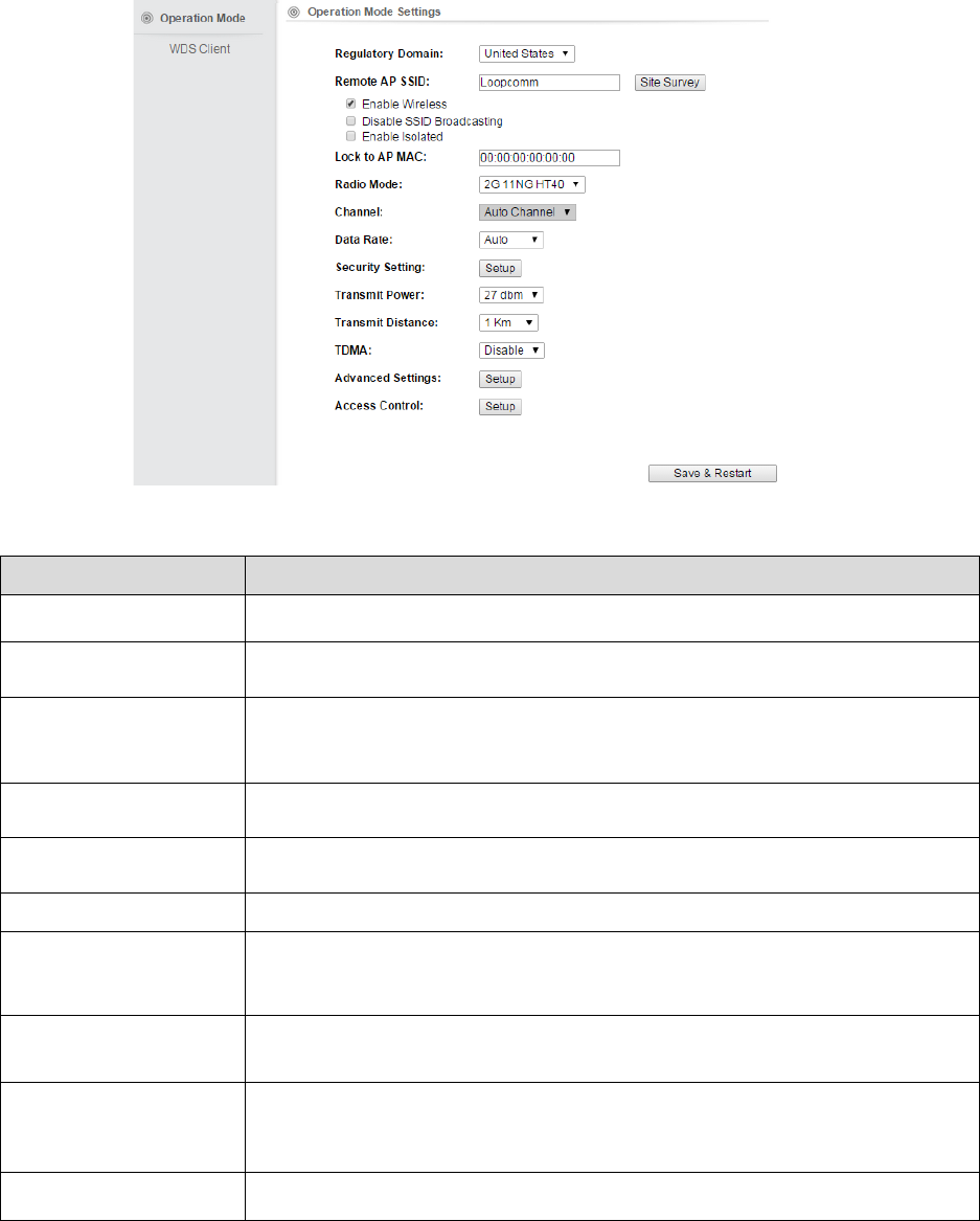
42
Fields
Description
Regulatory Domain Select the country from pull down menu.
Remote AP SSID
Select Site Survey option then it will Scan & displays the SSID List, Choose one SSID
from the list.
Enable Wireless
Disable SSID Broadcasting
Enable Isolated
Enable Wireless Option
SSID will be hidden, only users who know the SSID can associate with this network.
User cannot Ping.
Lock to AP Mac Enter MAC address of the access point to which the client will be locked and
connected.
Radio Mode Select the Mode of 2G 11NG HT20 or 2G 11NG HT40
“Auto” option selects the mode by itself.
Channel Select the wireless communication frequency/channel from pull-down menu.
Data Rate Defines the data rate (in Mbps) at which the device should transmit wireless
packets. You can fix a specific data rate between MCS 0 and MCS 7 (or MCS 15 for
2x2 chain devices).
Transmit Power Defines the maximum average transmit output power (in dBm) of the device. The
transmit power level maximum is limited according to country regulations.
Transmit Distance Changing the distance value will change the ACK (Acknowledgement) timeout value
accordingly, so it means the distance should be set as real distance between LP-
2396K and other device for accurate transmission performance.
Save and Restart It saves the new settings and restarts.

43
Site Survey
You could configure AP Client parameters here.
Click Rescan to browse more networks then select the SSID and press associate then close the page.
Note: Enter the SSID Password, if necessary.
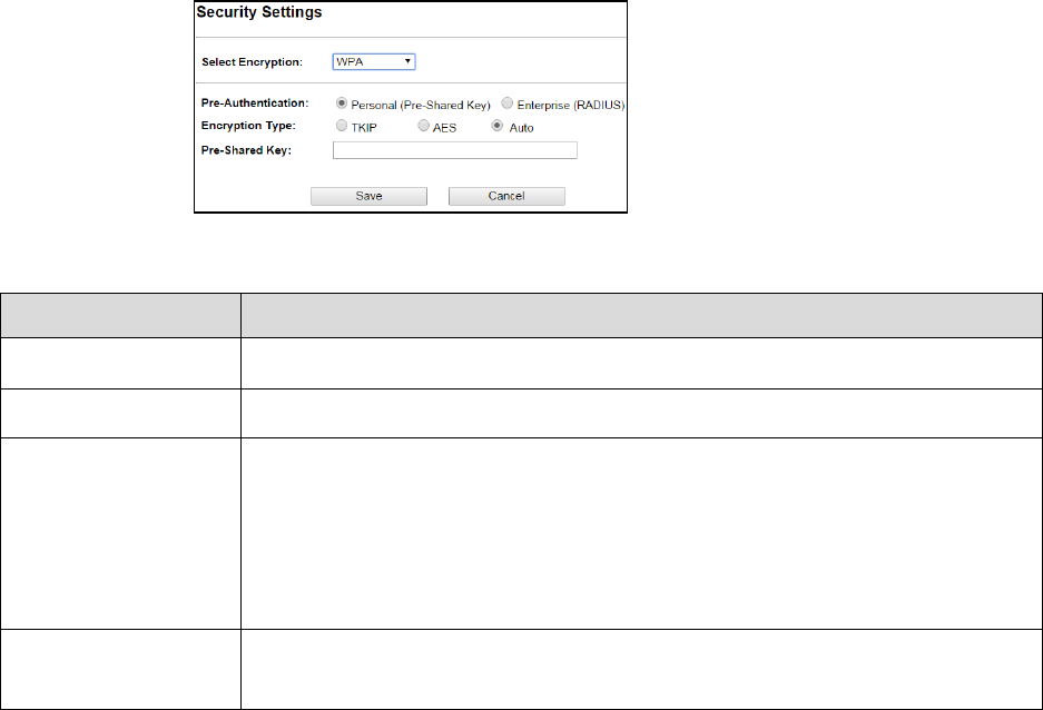
Security Settings
Security settings allow you to use encryption to secure your data.
There are 4 Encryption Modes in Security Settings. They are WEP, WPA, WPA2, and WPA-Mixed.
Functions are same for all Modes, below example is for WEP and WPA Encryption.
Fields Description
Select Encryption Select the Encryption Mode from the pull down menu.
Authentication Open System: Open system authentication provides identification for using the wireless
adapter's MAC address. Open system authentication is used when no authentication is
required.
Shared Key: It verifies that an authentication-initiating station has knowledge of a
shared secret. The 802.11 standard currently assumes that the shared secret is
delivered to the participating wireless clients by means of a more secure channel that is
independent of IEEE 802.11
Auto: Auto is the default authentication algorithm. It will change its authentication type
automatically to fulfill client’s requirement.
Key Length Select the Key length
Key Format When Key Length is selected as 64-bites then Input ASCII (5 Characters) or Hex (10
Characters)
When Key Length is selected as 128-bits then Input ASCII (13 Characters) or Hex (128
Character)
Encryption Key User can enter the characters based on selected Key Length & Key Format. The format
can be passphrase or characters.
44
Fields Description
Select Encryption Select the Encryption Mode from the pull down menu.
Pre-Authentication Select Pre-Authentication as Personal or Enterprise.
Encryption Type TKIP: Temporal Key Integrity Protocol (TKIP) for data Encryption. TKIP utilizes a
stronger encryption method and incorporates Message Integrity Code (MIC) to
provide protection against hackers.
AES: Advanced Encryption Standard (AES) for data encryption. AES utilizes a
symmetric 128-bit block data encryption.
AUTO: Auto is the default Encryption Type. It will change automatically to fulfill
client’s requirement.
Pre-shared Key User can enter Maximum number of Key Length. The format can be passphrase or
any characters.
45
Fields
Description
RADIU Server IP Address Enter the RADIU Server’s IP Address provided by your ISP.
RADIU Server Port Enter the RADIUS Server’s port number provided by your ISP.
RADIU Server Password Enter the RADIUS Server’s Password provided by your ISP.
EAP Reauthorization
Period
EAP- Session timeout interval for 802.1x re-authorization setting. Session timeout
interval unit is seconds
RSN Reauthorization Enable/Disable the function to access.
WPA Group Rekey Interval A group key is used for multicast/broadcast data, and the re-key interval is time
period that the system will change the group key periodically. The shorter the
interval is, better the security. It varies from 300 to 3600 Seconds.
Save
Cancel
Click Save to change the new settings.
Click cancel to clear the entered settings.
46
Advanced Settings
Fields Description
RTS/CTS Threshold Determines the packet size of a transmission and, through the use of an
AP, helps control traffic flow. The range is 0-2347 bytes.
Beacon Interval Beacons are the packets sending by Access point to synchronize the
wireless network. The beacon interval is the time interval between
beacons sending by this unit in AP or AP+WDS operation. The default and
recommended beacon interval is 100 milliseconds.
DTIM (Delivery Traffic Indication
Map)
This is the Delivery Traffic Indication Map. It is used to alert the clients that
multicast and broadcast packets buffered at the AP will be transmitted
immediately after the transmission of this beacon frame. You can change
the value from 1 to 255. The AP will check the buffered data according to
this value. For example, selecting “1” means to check the buffered data at
every beacon.
Fragment Size A large data frame is fragmented into several fragments each of size equal
to fragment threshold. By tuning the fragment threshold value, we can get
varying fragment sizes.
Short GI (Guard Interval) A GI is a period of time between symbol transmission that allows
reflections (from multipath) from the previous data transmission to settle
before transmitting a new symbol. The 802.11n draft specifies two guard
intervals: 400ns (short) and 800ns (long). Support of the 400ns GI is
optional for transmit and receive. The purpose of a guard interval is to
introduce immunity to propagation delays, echoes, and reflections to
which digital data is normally very sensitive.

47
Aggregation A part of the 802.11n standard that allows sending multiple frames per
single access to the medium by combining frames together into one larger
frame. It creates the larger frame by combining smaller frames with the
same physical source, destination end points, and traffic class (QoS) into
one large frame with a common MAC header
Aggregated Frames Number Determines the number of frames combined in the new larger frame.
Maximum Aggregated Size Determines the size (in bytes) of the larger frame.
Tx/Rx ChainMask
Displays the number of independent spatial data streams the device is
transmitting (TX) and receiving (RX) simultaneously within one spectral
channel of bandwidth. Multiple chains increase data transfer performance
significantly
WMM Capable Enable the feature to access or Disable it.
WMM Configuration Displays the WMM Parameters of station and Access Point
Save
Cancel
Save the changed settings
Cancel the selected settings
48
Access Control
This page allows administrator to have Access Control by entering MAC address of client
stations. When this function is Enabled, MAC address can be added into access control list and
only those clients whose wireless MAC address are in the access control list will be able to
connect or disconnect the internet.
Fields Description
Wireless Access Control Mode
The Selections are:
Disable: Disable the wireless ACL feature.
Allow Listed: When this option is selected, no wireless clients except those
whose MAC addresses are in the current access control list will be able to
connect to internet.
Deny Listed: When this option is selected, all wireless clients except those
whose MAC addresses are in the current access control list will not be able to
connect to internet.
Mac Address Enter client MAC address and press “Apply Changes” button to add client MAC
address into current access control list.
Comment Make a comment for Wireless access control
Function buttons for the Access Control List:
Apply Changes
Click to add this entry into the Access Control List.
The Access Control List lists the client MAC addresses. Any wireless client with its MAC address
listed in this access control list will be able to connect to the device. You can select the entries
at the Select column and apply to the following function buttons.
Delete Selected: Delete the selected entries from the list.
Delete All: Flush the list.
Reset: Clear the settings.
49
4.1.5 AP Router
It connects an external network (WAN) with an internal network (LAN/WLAN), to allow
cross-communication
Note: Depending on the mode you choose, applicable settings will be enabled/ disabled
automatically.
Press setup, then below Screen is displayed.
Press OK to continue, then below page is displayed.
Note: In AP router secondary port will be WAN Port by default.
50
Fields Description
Regulatory Domain Select the country from pull down menu.
Network SSID It is the wireless network name. User can use the default SSID or change it.
(Special characters cannot be used).
Enable Wireless
Disable SSID Broadcasting
Enable Isolated
Enable Wireless Option
SSID will be hidden, only users who know the SSID can associate with this network.
User cannot Ping.
Radio Mode Select the Mode of 2G 11NG HT20 or 2G 11NG HT40
“Auto” option selects the mode by itself.
Channel Select the wireless communication frequency/channel from pull-down menu.
Data Rate
Defines the data rate (in Mbps) at which the device should transmit wireless
packets. You can fix a specific data rate between MCS 0 and MCS 7 (or MCS 15 for
2x2 chain devices).
Transmit Power Defines the maximum average transmit output power (in dBm) of the device. The
transmit power level maximum is limited according to country regulations.
51
Transmit Distance Changing the distance value will change the ACK (Acknowledgement) timeout value
accordingly, so it means the distance should be set as real distance between LP-
2396K and other device for accurate transmission performance.
Save and Restart It saves the new settings and restarts.
Security Settings
Security settings allow you to use encryption to secure your data.
There are 4 Encryption Modes in Security Settings. They are WEP, WPA, WPA2, and WPA-Mixed.
Functions are same for all Modes, below example is for WEP and WPA Encryption.
Fields Description
Select Encryption Select the Encryption Mode from the pull down menu.
Authentication Open System: Open system authentication provides identification for using the
wireless adapter's MAC address. Open system authentication is used when no
authentication is required.
Shared Key: It verifies that an authentication-initiating station has knowledge of a
shared secret. The 802.11 standard currently assumes that the shared secret is
delivered to the participating wireless clients by means of a more secure channel that
is independent of IEEE 802.11
Auto: Auto is the default authentication algorithm. It will change its authentication
type automatically to fulfill client’s requirement.
Key Length Select the Key length
Key Format When Key Length is selected as 64-bites then Input ASCII (5 Characters) or Hex (10
Characters)
When Key Length is selected as 128-bits then Input ASCII (13 Characters) or Hex (128
Character)
Encryption Key User can enter the characters based on selected Key Length & Key Format. The
format can be passphrase or characters.
52
Fields Description
Select Encryption Select the Encryption Mode from the pull down menu.
Pre-Authentication Select Pre-Authentication as Personal or Enterprise.
Encryption Type TKIP: Temporal Key Integrity Protocol (TKIP) for data Encryption. TKIP utilizes a
stronger encryption method and incorporates Message Integrity Code (MIC) to provide
protection against hackers.
AES: Advanced Encryption Standard (AES) for data encryption. AES utilizes a symmetric
128-bit block data encryption.
AUTO: Auto is the default Encryption Type. It will change automatically to fulfill client’s
requirement.
Pre-shared Key
User can enter Maximum number of Key Length. The format can be passphrase or any
characters.
53
Fields Description
RADIU Server IP Address Enter the RADIU Server’s IP Address provided by your ISP.
RADIU Server Port Enter the RADIUS Server’s port number provided by your ISP.
RADIU Server Password Enter the RADIUS Server’s Password provided by your ISP.
EAP Reauthorization
Period
EAP- Session timeout interval for 802.1x re-authorization setting. Session timeout
interval unit is seconds
RSN Reauthorization Enable/Disable the function to access.
WPA Group Rekey Interval A group key is used for multicast/broadcast data, and the re-key interval is time
period that the system will change the group key periodically. The shorter the
interval is better the security. It varies from 300 to 3600 Seconds.
Save
Cancel
Click Save to change the new settings.
Click cancel to clear the entered settings.
54
Advanced Settings
Fields Description
RTS/CTS Threshold Determines the packet size of a transmission and, through the use of an
AP, helps control traffic flow. The range is 0-2347 bytes.
Beacon Interval Beacons are the packets sending by Access point to synchronize the
wireless network. The beacon interval is the time interval between
beacons sending by this unit in AP or AP+WDS operation. The default and
recommended beacon interval is 100 milliseconds.
DTIM (Delivery Traffic Indication
Map)
This is the Delivery Traffic Indication Map. It is used to alert the clients that
multicast and broadcast packets buffered at the AP will be transmitted
immediately after the transmission of this beacon frame. You can change
the value from 1 to 255. The AP will check the buffered data according to
this value. For example, selecting “1” means to check the buffered data at
every beacon.
Fragment Size A large data frame is fragmented into several fragments each of size equal
to fragment threshold. By tuning the fragment threshold value, we can get
varying fragment sizes.
Short GI (Guard Interval) A GI is a period of time between symbol transmission that allows
reflections (from multipath) from the previous data transmission to settle
before transmitting a new symbol. The 802.11n draft specifies two guard
intervals: 400ns (short) and 800ns (long). Support of the 400ns GI is
optional for transmit and receive. The purpose of a guard interval is to
introduce immunity to propagation delays, echoes, and reflections to
which digital data is normally very sensitive.

55
Aggregation A part of the 802.11n standard that allows sending multiple frames per
single access to the medium by combining frames together into one larger
frame. It creates the larger frame by combining smaller frames with the
same physical source, destination end points, and traffic class (QoS) into
one large frame with a common MAC header
Aggregated Frames Number Determines the number of frames combined in the new larger frame.
Maximum Aggregated Size Determines the size (in bytes) of the larger frame.
Tx/Rx ChainMask
Displays the number of independent spatial data streams the device is
transmitting (TX) and receiving (RX) simultaneously within one spectral
channel of bandwidth. Multiple chains increase data transfer performance
significantly
WMM Capable Enable the feature to access or Disable it.
WMM Configuration Displays the WMM Parameters of station and Access Point
Save
Cancel
Save the changed settings
Cancel the selected settings.
56
Access Control
This page allows administrator to have Access Control by entering MAC address of client
stations. When this function is Enabled, MAC address can be added into access control list and
only those clients whose wireless MAC address are in the access control list will be able to
connect or disconnect the internet.
Fields Description
Wireless Access Control Mode The Selections are:
Disable: Disable the wireless ACL feature.
Allow Listed: When this option is selected, no wireless clients except those
whose MAC addresses are in the current access control list will be able to
connect to internet.
Deny Listed: When this option is selected, all wireless clients except those
whose MAC addresses are in the current access control list will not be able to
connect to internet.
Mac Address Enter client MAC address and press “Apply Changes” button to add client MAC
address into current access control list.
Comment Make a comment for Wireless access control
Function buttons for the Access Control List:
Apply Changes
Click to add this entry into the Access Control List.
The Access Control List lists the client MAC addresses. Any wireless client with its MAC address
listed in this access control list will be able to connect to the device. You can select the entries
at the Select column and apply to the following function buttons.
Delete Selected: Delete the selected entries from the list.
Delete All: Flush the list.
Reset: Clear the settings.
57
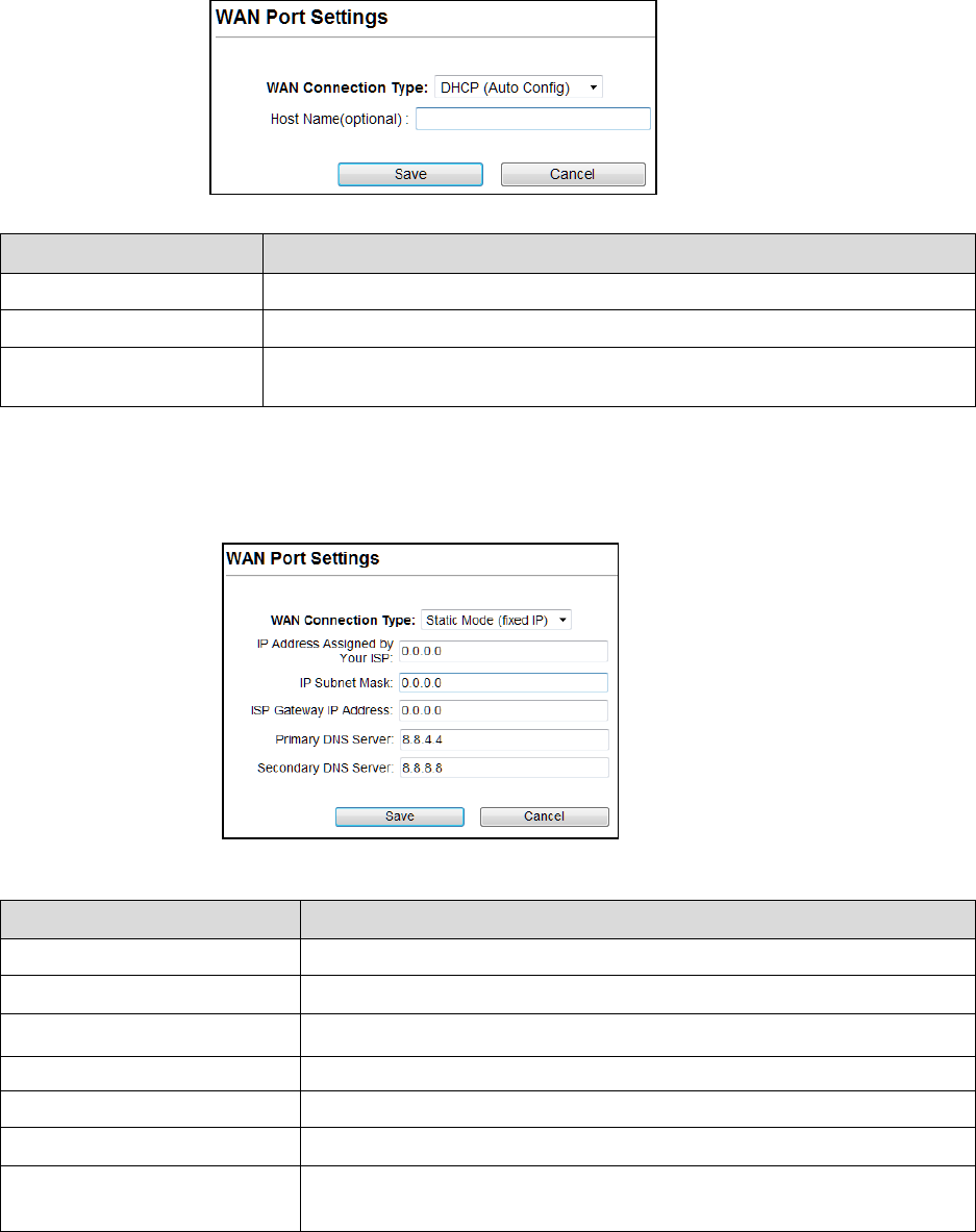
WAN Port Settings
There are three options DHCP, Static Mode, PPPoE for Internet connection on WAN port.
DHCP (Auto Config)
Fields Description
WAN Connection Type Select DHCP from pull down menu
Host Name Enter the Host Name of DHCP server. The default value is empty.
Save
Cancel
Click Save to change the new settings.
Click cancel to clear the entered settings.
Static Mode (fixed IP)
Fields
Description
WAN Connection Type Select Static Mode from pull down menu.
IP Address
Enter the IP address.
IP Subnet Mask Enter the subnet mask for WAN interface.
Gateway IP address Enter the default gateway for WAN interface outgoing data packets.
Primary DNS Server Enter the IP address of Domain Name Server 1.
Secondary DNS Server
Enter the IP address of Domain Name Server 2.
Save
Cancel
Click Save to change the new settings.
Click cancel to clear the entered settings.
58
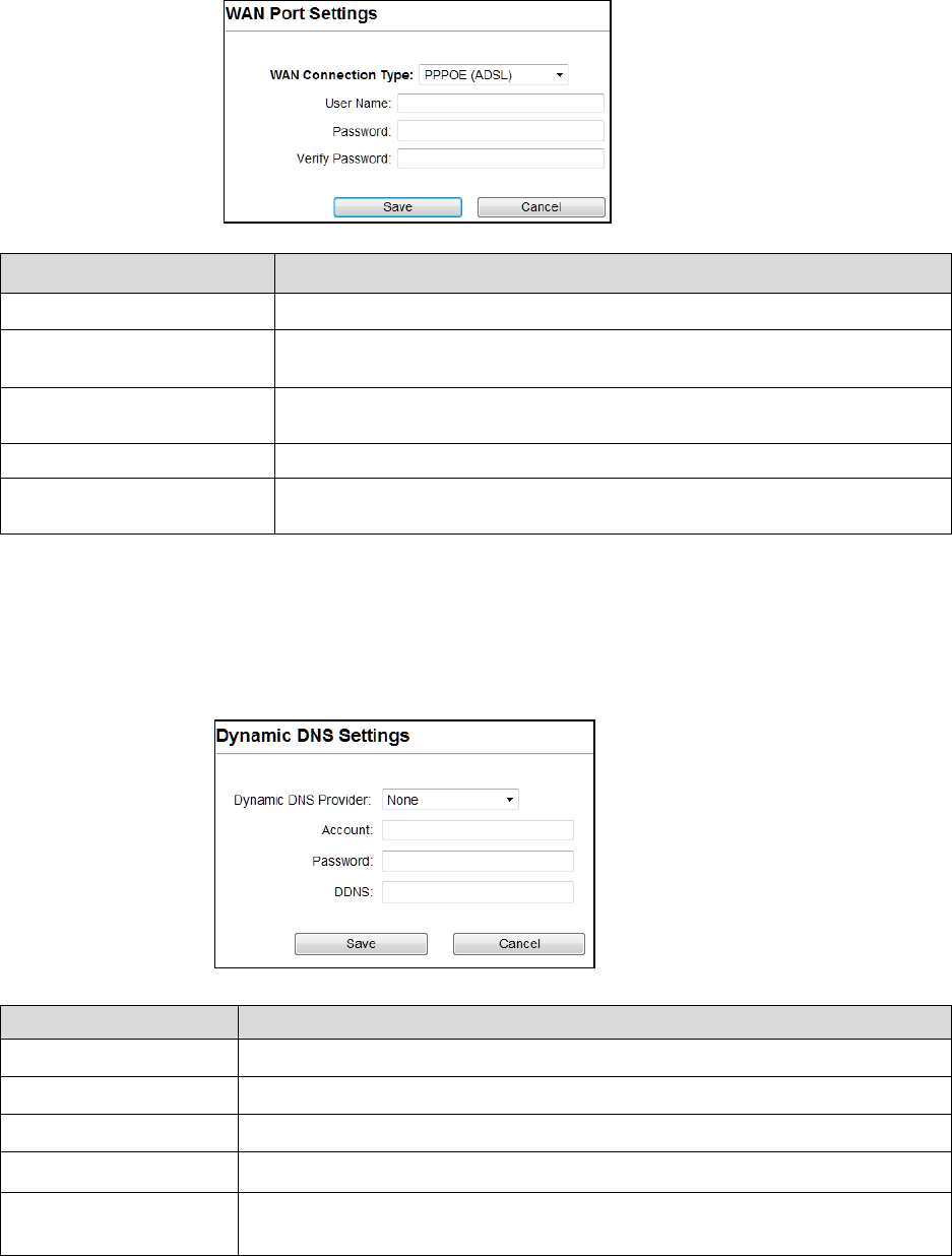
PPPoE (ADSL)
Fields Description
WAN connection Type Select PPPoE from pull down menu
User Name If you select the PPPoE support on WAN interface, Enter the user name to
login the PPPoE server Provided by ISP
Password If you select the PPPoE support on WAN interface, Enter the password to login
the PPPoE server Provided by ISP
Verify Password Enter the same password again for verification.
Save:
Cancel
Click Save to change the new settings.
Click cancel to clear the entered settings.
Dynamic DNS Settings
The Dynamic DNS features allow you to register your device with a DNS server and access your
device each time using the same host name
Fields Description
Dynamic DNS Provider Click the drop down menu to pick up the right DDNS provider you registered.
Account Enter the account of DDNS you registered.
Password Password assigned by the DDNS service provider.
DDNS Enter the domain name that you registered.
Save
Cancel
Click Save to change the new settings.
Click cancel to clear the entered settings.
59
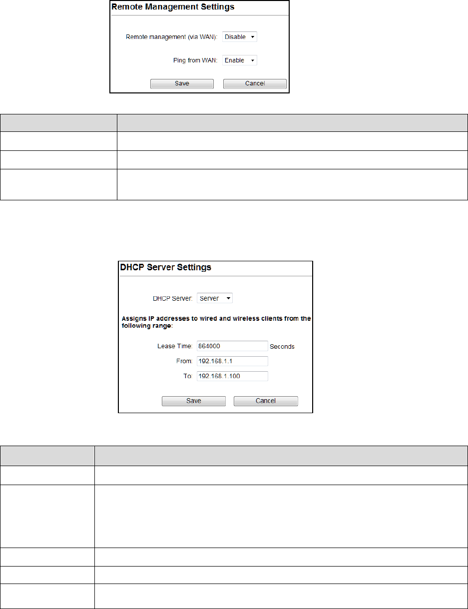
Remote Management
Fields Description
Remote Management Select Enable or Disable for remote management function.
Ping from WAN Select Disable or Enable for Ping permit from WAN.
Save
Cancel
Click Save to change the new settings.
Click cancel to clear the entered settings.
DHCP Server Settings
Fields Description
DHCP Server Select Server to access the feature.
Lease Time The Lease Time is the amount of time that a network user is allowed to maintain a
network connection to the device using the current dynamic IP address. At the end of the
Lease Time, the lease is either renewed or a new IP is issued by the DHCP server. The
amount of time is in units of seconds. The default value is 864000 seconds (1 day). The
value –1 stands for the infinite lease.
From Enter Start Address of the DHCP Client address range.
To
Enter End Address of the DHCP Client address range.
Save
Cancel
Click Save to change the new settings.
Click cancel to clear the entered settings.
60
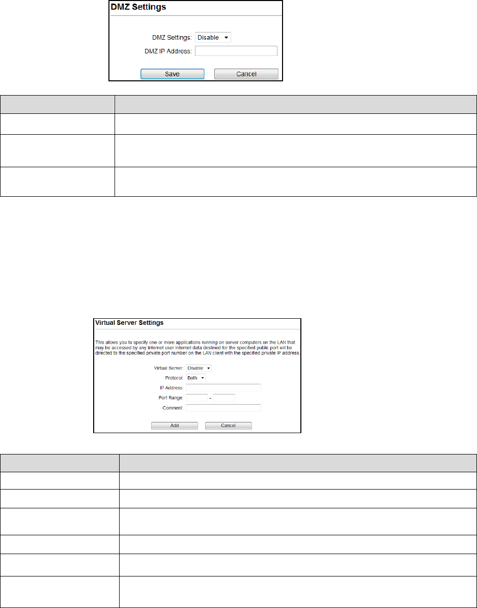
DMZ Settings
You may setup a De-Militarized (DMZ) to separate internal network and internet.
Fields Description
DMZ Settings Enable or Disable the DMZ function.
DMZ IP Address To support DMZ in your firewall design, Enter IP address of DMZ host that can be
access from the WAN interface.
Save
Cancel
Click Save to change the new settings.
Click cancel to clear the entered settings.
Virtual Server Settings
Virtual server feature allows users to make servers on your LAN accessible to internet users.
Normally, Internet users would not be able to access a server on your LAN because of native
NAT protection.The “virtual server” feature solves these problems and allows internet users to
connect to your servers
Fields Description
Virtual Server Select Enable or Disable the Virtual Server function.
Protocol There are 3 options, TCP&UDP, TCP or UDP.
IP Address Enter the IP address to which the data packets can be forwarded from WAN. The IP
address should be hosted in LAN behind the NAT firewall.
Port Range Enter the port range to which data packets can be forwarded.
Comment Make a comment for the Virtual Server policy.
Add
Cancel
Click Add to change the new settings.
Click cancel to clear the entered settings.
61
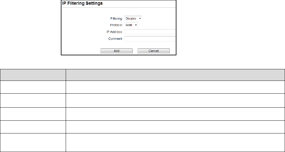
IP Filtering Settings
The IP filtering feature allows you to deny specific IP address which cannot connect to internet.
Fields Description
Filtering Enable/Disable the function to IP Filter
Protocol Specify protocol, TCP&UDP, TCP or UDP.
IP Address Enter the specific IP Address to be denied.
Comment Make a comment for the IP Filtering policy.
Add
Cancel
Click Add to change the new settings.
Click cancel to clear the entered settings.
62
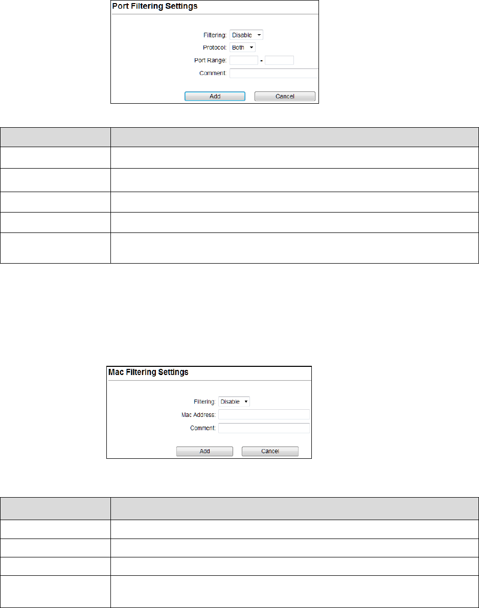
Port Filtering Settings
The Port filtering feature allows you to deny specific Ports which cannot connect to internet.
Fields Description
Filtering Enable/Disable the function to Port Filter
Protocol Specify the protocol TCP&UDP, TCP or UDP.
Port Range Enter the specific Port range to be denied.
Comment Make a comment for the Port Filtering policy.
Add
Cancel
Click Add to change the new settings.
Click cancel to clear the entered settings.
MAC Filtering Settings
The MAC filtering feature allows you to deny MAC address which cannot connect to internet.
Fields Description
Filtering Select Enable/Disable the Mac Filtering function.
Mac Address Enter the specific MAC address to be denied.
Comment Make a comment for the filtering policy.
Add
Cancel
Click Add to change the new settings.
Click cancel to clear the entered settings.
63
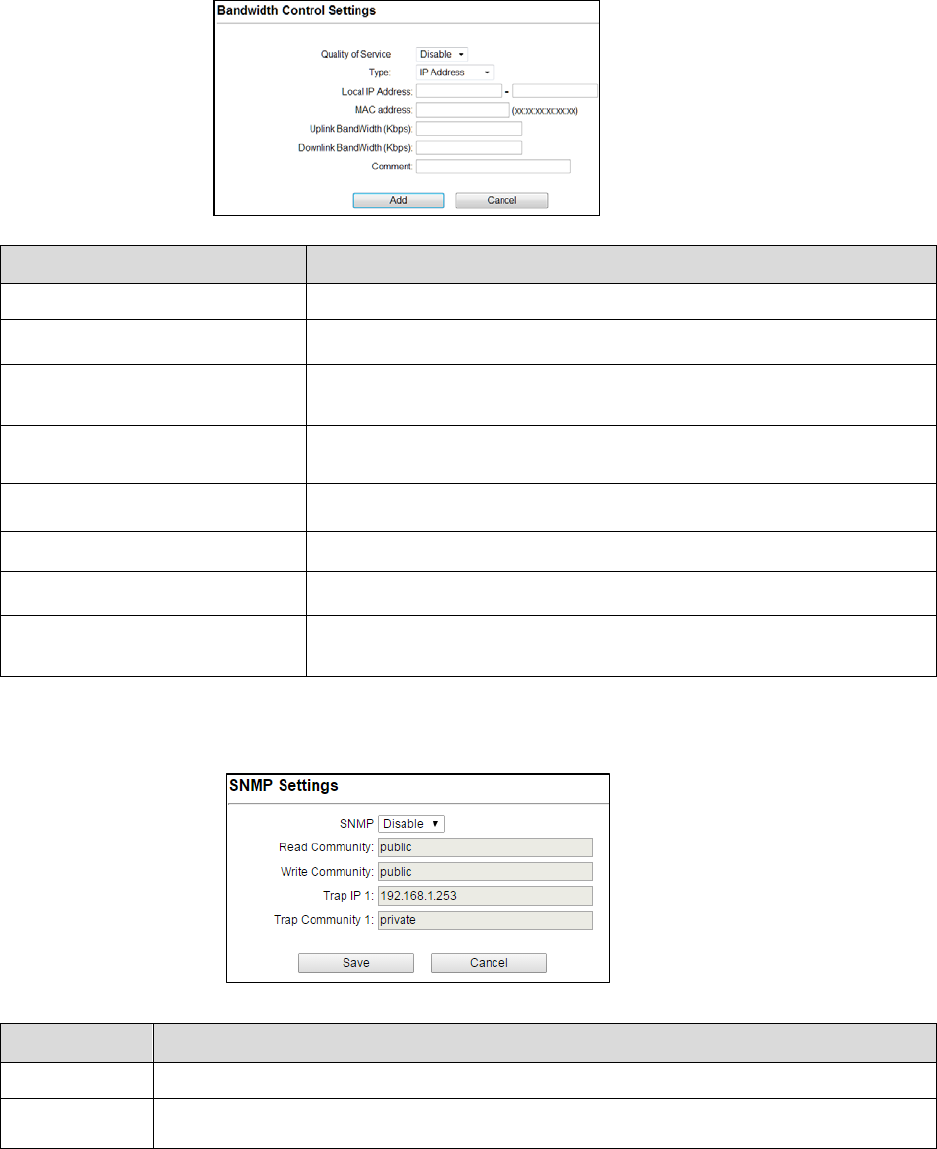
Bandwidth Control
Bandwidth controls the transmission speed of IP address and MAC address. Router can use
bandwidth control to limit the Internet connection speed of IP address or MAC address.
Fields Description
Quality of Service Enable/Disable the function
Type The two type options are IP Address and Mac address
Local IP Address If you select IP Address, then Enter the IP Address of the device/PC
connected to the router.
MAC Address If you select MAC Address, then Enter the MAC Address of the device/PC
connected to the router.
Uplink Bandwidth (Kbps) Enter the limit for uplink bandwidth
Downlink Bandwidth (Kbps) Enter the limit for downlink bandwidth
Comment Make a comment for Bandwidth Control
Add
Cancel
Click Add to change the new settings.
Click cancel to clear the entered settings.
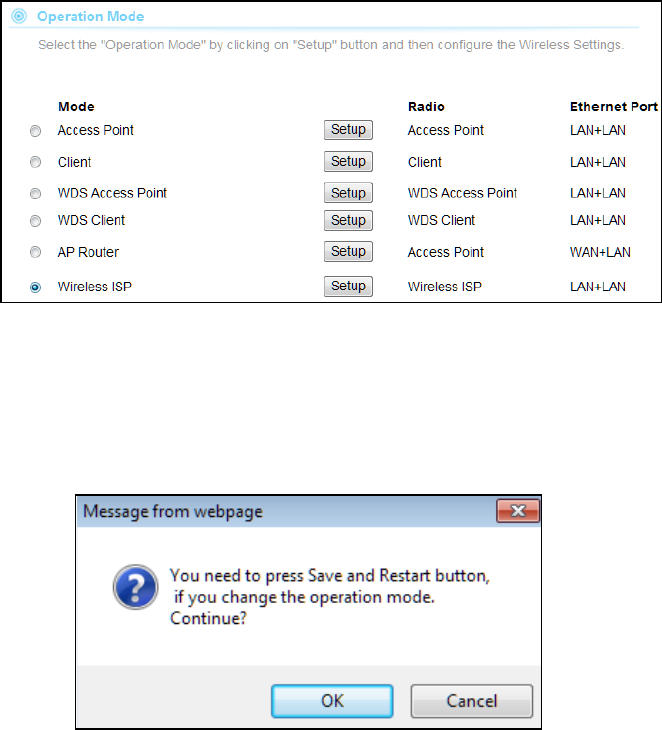
SNMP Settings
Fields Description
SNMP
Enable/Disable the feature to access.
Save
Cancel
Click Save to change the new settings.
Click cancel to clear the entered settings.
64
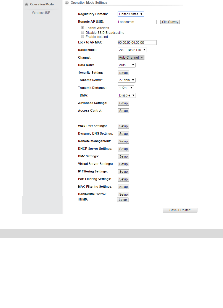
4.1.6 Wireless ISP
A Wireless Internet Service Provider (WISP) is an internet Service Provider with a network
based on wireless networking.
Note: Depending on the mode you choose, applicable settings will be enabled/ disabled
automatically.
Press setup, then below Screen is displayed.
Press OK to continue, then below page is displayed.
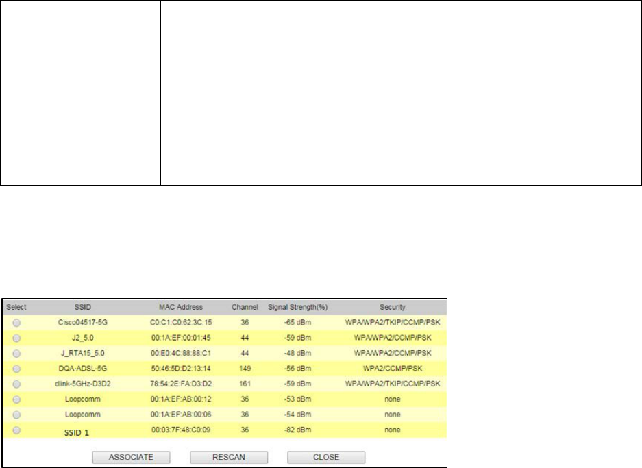
65
Fields
Description
Regulatory Domain Select the country from pull down menu.
Remote AP SSID Select Site Survey option then it will Scan & displays the SSID List, Choose one SSID
from the list.
Enable Wireless
Disable SSID Broadcasting
Enable Isolated
Enable Wireless Option
SSID will be hidden, only users who know the SSID can associate with this network.
User cannot Ping.
Radio Mode Select the Mode of 2G 11NG HT20 or 2G 11NG HT40
“Auto” option selects the mode by itself.
Channel Select the wireless communication frequency/channel from pull-down menu.
66
Data Rate Defines the data rate (in Mbps) at which the device should transmit wireless
packets. You can fix a specific data rate between MCS 0 and MCS 7 (or MCS 15 for
2x2 chain devices).
Transmit Power Defines the maximum average transmit output power (in dBm) of the device. The
transmit power level maximum is limited according to country regulations.
Transmit Distance Changing the distance value will change the ACK (Acknowledgement) timeout value
accordingly, so it means the distance should be set as real distance between LP-
2396K and other device for accurate transmission performance.
Save and Restart
It saves the new settings and restarts.
Site Survey
You could configure AP Client parameters here.
Click Rescan to browse more networks then select the SSID and press associate then close the
page.
Note: Enter the SSID Password, if necessary.
67
Security Settings
Security settings allow you to use encryption to secure your data.
There are 4 Encryption Modes in Security Settings. They are WEP, WPA, WPA2, and WPA-Mixed.
Functions are same for all Modes, below example is for WEP and WPA Encryption.
Fields Description
Select Encryption Select the Encryption Mode from the pull down menu.
Authentication Open System: Open system authentication provides identification for using the
wireless adapter's MAC address. Open system authentication is used when no
authentication is required.
Shared Key: It verifies that an authentication-initiating station has knowledge of a
shared secret. The 802.11 standard currently assumes that the shared secret is
delivered to the participating wireless clients by means of a more secure channel that
is independent of IEEE 802.11
Auto: Auto is the default authentication algorithm. It will change its authentication
type automatically to fulfill client’s requirement.
Key Length Select the Key length
Key Format When Key Length is selected as 64-bites then Input ASCII (5 Characters) or Hex (10
Characters)
When Key Length is selected as 128-bits then Input ASCII (13 Characters) or Hex (128
Character)
Encryption Key User can enter the characters based on selected Key Length & Key Format. The
format can be passphrase or characters.
68
Fields Description
Select Encryption Select the Encryption Mode from the pull down menu.
Pre-Authentication Select Pre-Authentication as Personal or Enterprise.
Encryption Type TKIP: Temporal Key Integrity Protocol (TKIP) for data Encryption. TKIP utilizes a
stronger encryption method and incorporates Message Integrity Code (MIC) to
provide protection against hackers.
AES: Advanced Encryption Standard (AES) for data encryption. AES utilizes a
symmetric 128-bit block data encryption.
AUTO: Auto is the default Encryption Type. It will change automatically to fulfill
client’s requirement.
Pre-shared Key User can enter Maximum number of Key Length. The format can be passphrase or
any characters.
69
Fields Description
RADIU Server IP Address Enter the RADIU Server’s IP Address provided by your ISP.
RADIU Server Port Enter the RADIUS Server’s port number provided by your ISP.
RADIU Server Password Enter the RADIUS Server’s Password provided by your ISP.
EAP Reauthorization
Period
EAP- Session timeout interval for 802.1x re-authorization setting. Session timeout
interval unit is seconds
RSN Reauthorization Enable/Disable the function to access.
WPA Group Rekey Interval A group key is used for multicast/broadcast data, and the re-key interval is time
period that the system will change the group key periodically. The shorter the
interval is better the security.it varies from 300 to 3600 Seconds.
Save
Cancel
Click Save to change the new settings.
Click cancel to clear the entered settings.
70
Advanced Settings
Fields Description
RTS/CTS Threshold
Determines the packet size of a transmission and, through the use of an AP, helps
control traffic flow. The range is 0-2347 bytes.
Beacon Interval Beacons are the packets sending by Access point to synchronize the wireless
network. The beacon interval is the time interval between beacons sending by this
unit in AP or AP+WDS operation. The default and recommended beacon interval is
100 milliseconds.
DTIM (Delivery Traffic
Indication Map)
This is the Delivery Traffic Indication Map. It is used to alert the clients that
multicast and broadcast packets buffered at the AP will be transmitted
immediately after the transmission of this beacon frame. You can change the
value from 1 to 255. The AP will check the buffered data according to this value.
For example, selecting “1” means to check the buffered data at every beacon.
Fragment Size A large data frame is fragmented into several fragments each of size equal to
fragment threshold. By tuning the fragment threshold value, we can get varying
fragment sizes.
Short GI (Guard Interval) A GI is a period of time between symbol transmission that allows reflections (from
multipath) from the previous data transmission to settle before transmitting a
new symbol. The 802.11n draft specifies two guard intervals: 400ns (short) and
800ns (long). Support of the 400ns GI is optional for transmit and receive. The
purpose of a guard interval is to introduce immunity to propagation delays,
echoes, and reflections to which digital data is normally very sensitive.
Aggregation A part of the 802.11n standard that allows sending multiple frames per single
access to the medium by combining frames together into one larger frame. It
creates the larger frame by combining smaller frames with
the same physical source, destination end points, and traffic class (QoS) into one
large frame with a common MAC header

71
Aggregated Frames
Number
Determines the number of frames combined in the new larger frame.
Maximum Aggregated Size
Determines the size (in bytes) of the larger frame.
Tx/Rx ChainMask Displays the number of independent spatial data streams the device is
transmitting (TX) and receiving (RX) simultaneously within one spectral channel of
bandwidth. Multiple chains increase data transfer performance significantly.
WMM Capable
Enable the feature to access or Disable it.
WMM Configuration
Displays the WMM Parameters of station and Access Point
Save
Cancel
Save the changed settings
Cancel the selected settings
72
Access Control
This page allows administrator to have Access Control by entering MAC address of client
stations. When this function is Enabled, MAC address can be added into access control list and
only those clients whose wireless MAC address are in the access control list will be able to
connect or disconnect the internet.
Fields Description
Wireless Access Control Mode The Selections are:
Disable: Disable the wireless ACL feature.
Allow Listed: When this option is selected, no wireless clients except those
whose MAC addresses are in the current access control list will be able to
connect to internet.
Deny Listed: When this option is selected, all wireless clients except those
whose MAC addresses are in the current access control list will not be able to
connect to internet.
Mac Address Enter client MAC address and press “Apply Changes” button to add client MAC
address into current access control list.
Comment
Make a comment for Wireless access control
Function buttons for the Access Control List:
Apply Changes
Click to add this entry into the Access Control List.
The Access Control List lists the client MAC addresses. Any wireless client with its MAC address
listed in this access control list will be able to connect to the device. You can select the entries
at the Select column and apply to the following function buttons.
Delete Selected: Delete the selected entries from the list.
Delete All: Flush the list.
Reset: Clear the settings.
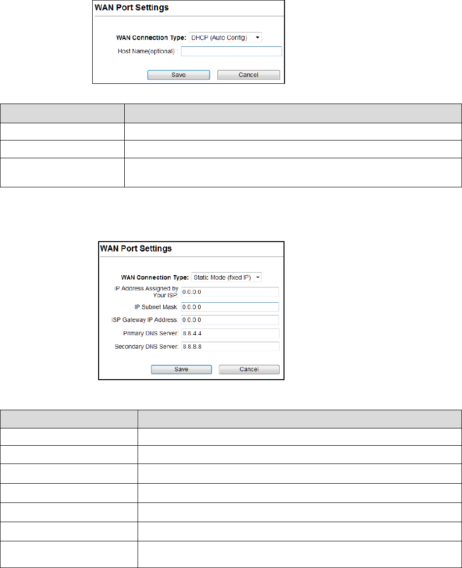
73
WAN Port Settings
There are three options DHCP, Static Mode, PPPOE for Internet connection on WAN port.
DHCP (Auto Config)
Fields
Description
WAN Connection Type Select DHCP from pull down menu
Host Name Enter the Host Name of DHCP server. The default value is empty.
Save
Cancel
Click Save to change the new settings.
Click cancel to clear the entered settings.
Static Mode (fixed IP)
Fields Description
WAN Connection Type Select Static Mode from pull down menu
IP Address Enter the IP address.
IP Subnet Mask Enter the subnet mask for WAN interface.
Gateway IP address Enter the default gateway for WAN interface outgoing data packets.
Primary DNS Server Enter the IP address of Domain Name Server 1.
Secondary DNS Server Enter the IP address of Domain Name Server 2.
Save
Cancel
Click Save to change the new settings.
Click cancel to clear the entered settings.
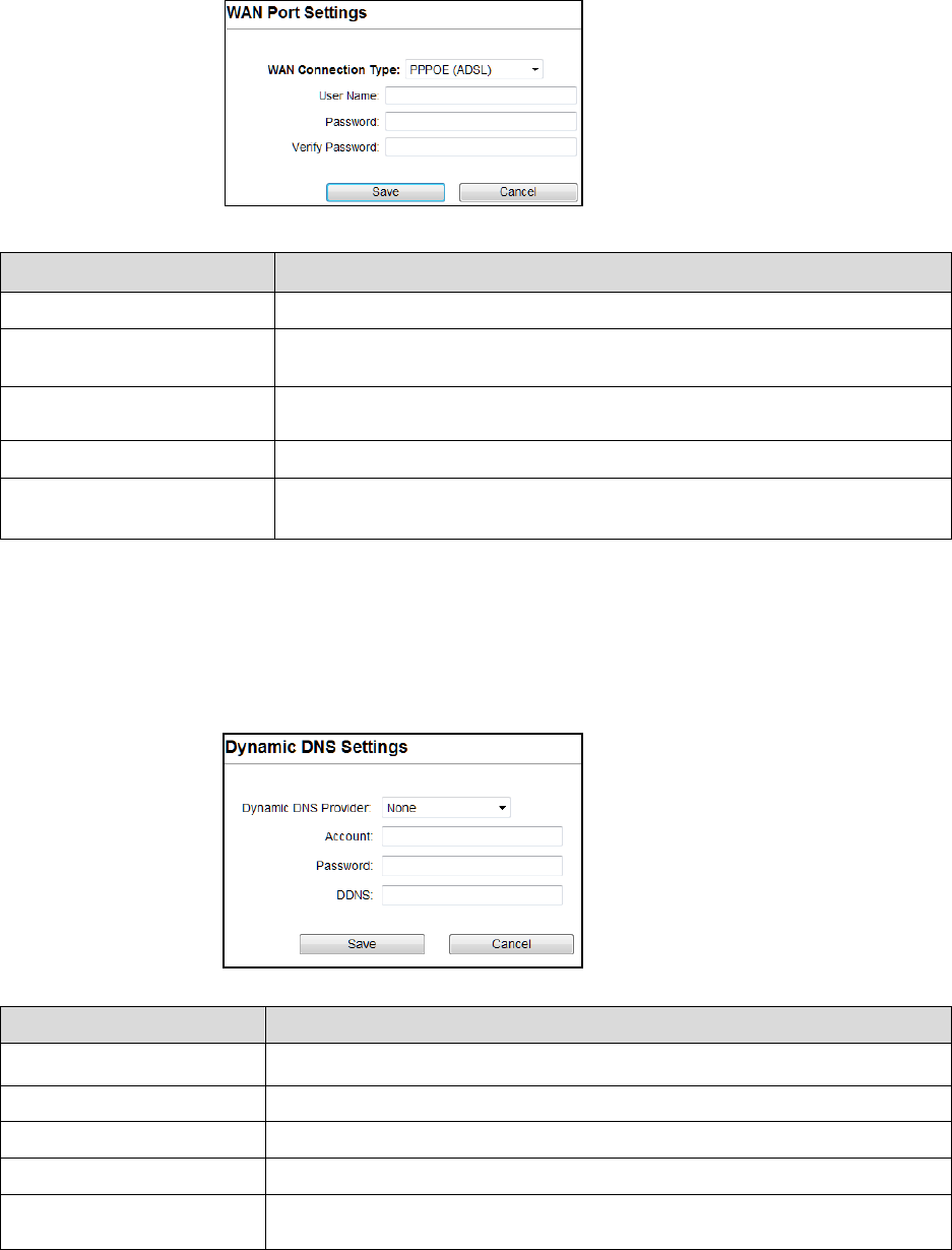
74
PPPoE (ADSL)
Fields Description
WAN connection Type Select PPPoE from pull down menu
User Name If you select the PPPoE support on WAN interface, Enter the user name to
login the PPPoE server provided by ISP.
Password If you select the PPPoE support on WAN interface, Enter the password to login
the PPPoE server provided by ISP.
Verify Password Enter the same password again for verification.
Save
Cancel
Click Save to change the new settings.
Click cancel to clear the entered settings.
Dynamic DNS Settings
The Dynamic DNS features allow you to register your device with a DNS server and access your
device each time using the same host name
Fields Description
Dynamic DNS Provider Click the drop down menu to pick up the right DDNS provider you registered.
Account Enter the account of DDNS you registered.
Password Password assigned by the DDNS service provider.
DDNS Enter the domain name that you registered.
Save
Cancel
Click Save to change the new settings.
Click cancel to clear the entered settings.
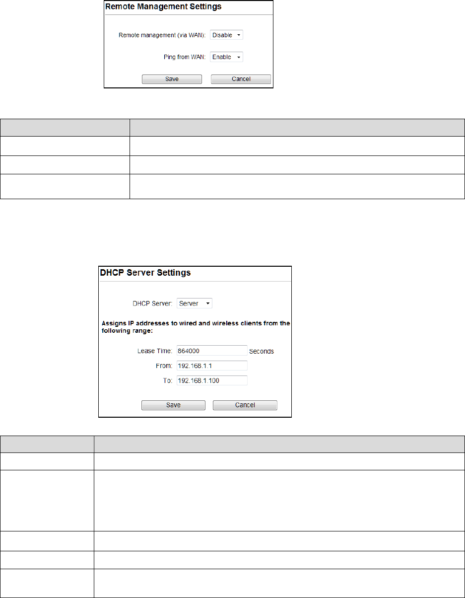
75
Remote Management
Fields
Description
Remote Management Select Enable or Disable for remote management function.
Ping from WAN Select Disable or Enable for Ping permit from WAN.
Save
Cancel
Click Save to change the new settings.
Click cancel to clear the entered settings.
DHCP Server Settings
Fields
Description
DHCP Server Select Server to access the feature
Lease Time The Lease Time is the amount of time that a network user is allowed to maintain a
network connection to the device using the current dynamic IP address. At the end of the
Lease Time, the lease is either renewed or a new IP is issued by the DHCP server. The
amount of time is in units of seconds. The default value is 864000 seconds (1 day). The
value –1 stands for the infinite lease.
From Enter Start address of the DHCP Client address range.
To
Enter End address of the DHCP Client address range.
Save
Cancel
Click Save to change the new settings.
Click cancel to clear the entered settings.
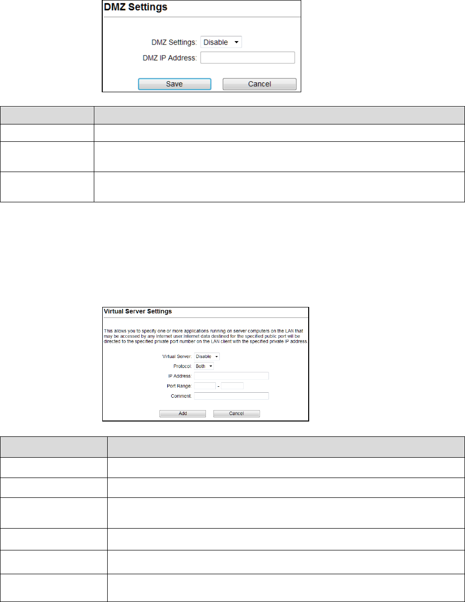
76
DMZ Settings
You may setup a De-Militarized (DMZ) to separate internal network and internet.
Fields Description
DMZ Settings Enable or Disable the DMZ function.
DMZ IP Address To support DMZ in your firewall design, Enter IP address of DMZ host that can be access
from the WAN interface.
Save
Cancel
Click Save to change the new settings.
Click cancel to clear the entered settings.
Virtual Server Settings
Virtual server feature allows users to make servers on your LAN accessible to internet users.
Normally, Internet users would not be able to access a server on your LAN because of native
NAT protection.The “virtual server” feature solves these problems and allows internet users to
connect to your servers
Fields Description
Virtual Server Select Enable or Disable the Virtual Server function.
Protocol There are 3 options, TCP&UDP, TCP or UDP.
IP Address Enter the IP Address to which the data packets can be forwarded from WAN. This IP
address should be hosted in LAN behind the NAT Firewall.
Port Range Enter the port range to which data packets can be forwarded.
Comment Make a comment for the Virtual Server policy.
Add
Cancel
Click Add to change the new settings.
Click cancel to clear the entered settings.
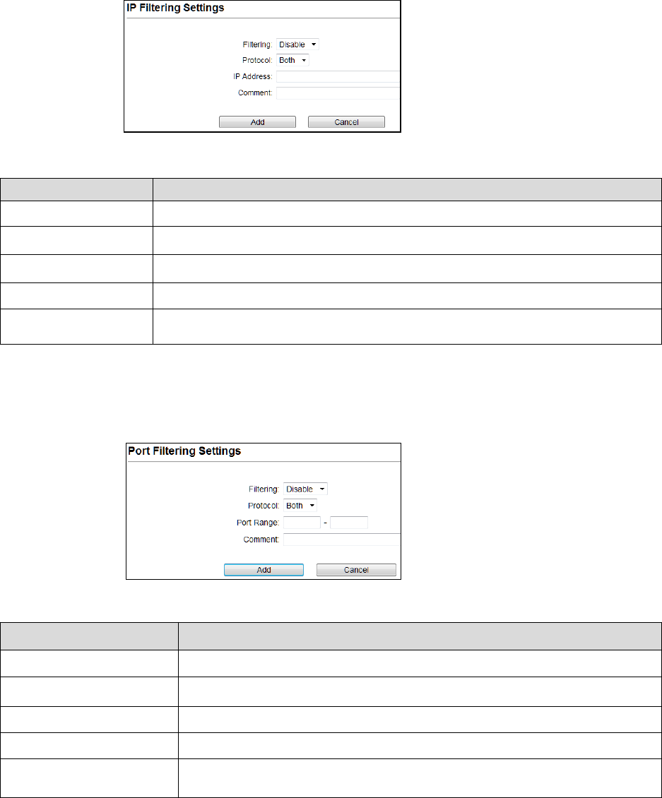
77
IP Filtering Settings
The IP filtering feature allows you to deny specific IP address which cannot connect to internet.
Fields Description
Filtering
Enable/Disable the function to IP Filter
Protocol
Specify protocol, TCP&UDP, TCP or UDP.
IP Address Enter the specific IP Address to be denied.
Comment Make a comment for the IP Filtering policy.
Add
Cancel
Click Add to change the new settings.
Click cancel to clear the entered settings.
Port Filtering Settings
The Port filtering feature allows you to deny specific Ports which cannot connect to internet.
Fields Description
Filtering Enable/Disable the function to Port Filter
Protocol Specify the protocol TCP&UDP, TCP or UDP.
Port Range Enter the specific Port range to be denied.
Comment Make a comment for the Port Filtering policy.
Add
Cancel
Click Add to change the new settings.
Click cancel to clear the entered settings.
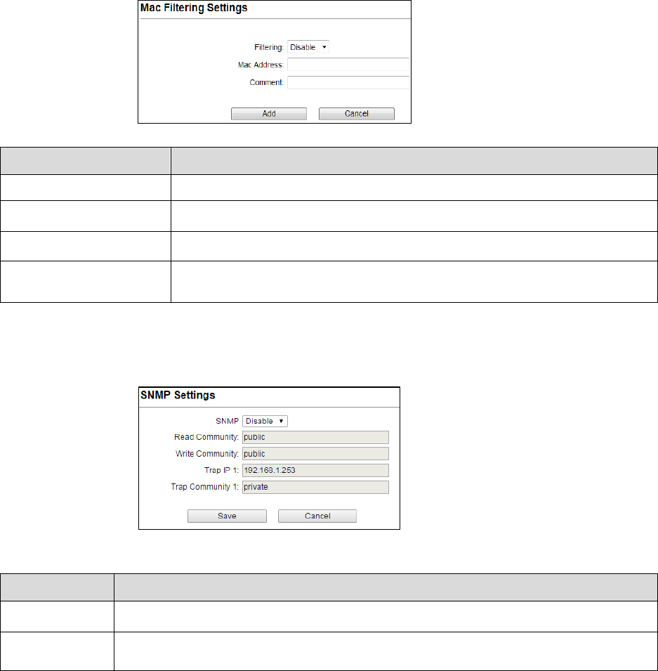
78
MAC Filtering Settings
The MAC filtering feature allows you to deny MAC address which cannot connect to internet
Fields Description
Filtering
Select Enable or Disable the Mac Filtering function.
Mac Address Enter the specific MAC address to be denied.
Comment Make a comment for the filtering policy.
Add
Cancel
Click Add to change the new settings.
Click cancel to clear the entered settings.
SNMP Settings
Fields Description
SNMP Enable/Disable the feature to access.
Save
Cancel
Click Save to change the new settings.
Click cancel to clear the entered settings.
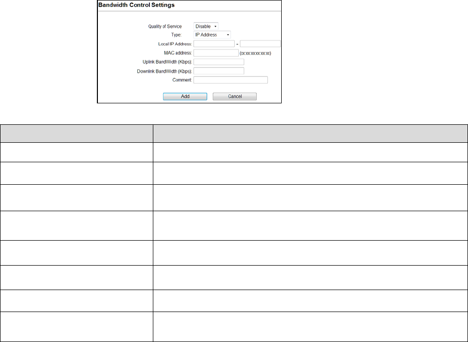
79
Bandwidth Control
Bandwidth controls the transmission speed of IP address and MAC address. Router can use
bandwidth control to limit the Internet connection speed of IP address or MAC address.
Fields Description
Quality of Service Enable/Disable the function
Type
The two type options are IP Address and Mac address
Local IP Address If you select IP Address, then Enter the IP Address of the device/PC
connected to the router.
MAC Address If you select MAC Address, then Enter the MAC Address of the device/PC
connected to the router.
Uplink Bandwidth (Kbps) Enter the limit for uplink bandwidth
Downlink Bandwidth (Kbps) Enter the limit for downlink bandwidth
Comment Make a comment for Bandwidth Control
Add
Cancel
Click Add to change the new settings.
Click cancel to clear the entered settings.
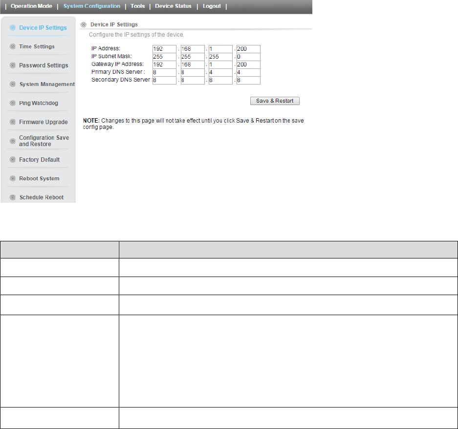
80
4.2 System Configuration
Select the System Configuration menu from the top of your screen to access IP. The system
configuration includes Device IP Settings, Time Settings, Password Settings, System
Management, Ping Watchdog, Firmware Upgrade, Configuration Save and Restore, Factory
Default, Reboot System.
4.2.1 Device IP Settings
All settings besides Wireless and WAN functions are in this category.
Fields Description
IP Address Enter the IP Address for the Device.
IP Subnet Mask
Enter the Subnet Mask as 255.255.0.0
Gateway IP Address Enter the Gateway IP Address for the Device.
DNS Server
Primary DNS Server
Secondary DNS Server
The Domain Name System (DNS) is a server on the Internet that translates logical
names such as “www.yahoo.com” to IP addresses like 66.218.71.80. In order to do
this, a query is made by the requesting device to a DNS server to provide the
necessary information. If your system administrator requires you to manually
enter the DNS Server addresses, you should enter them here.
Enter the Primary DNS Server
Enter the Secondary DNS Server
Save & Restart It saves the settings and restarts.
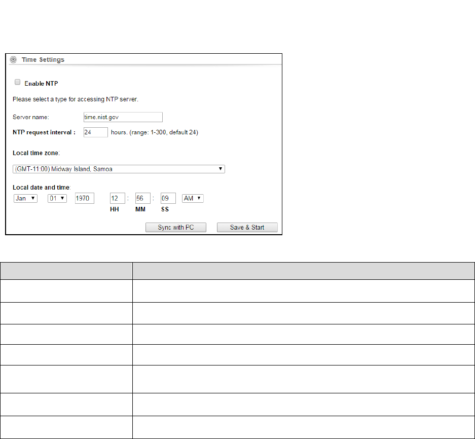
81
4.2.2 Time Settings
System Configuration ->Time Settings
It synchronizes the date & time of PC to device. Enable NTP (Network time protocol) for clock
synchronization to device. If NTP is not enabled then user must enter the date and time
manually.
Fields Description
Enable NTP Enable NTP so that time & date will be updated correctly even after reboot.
Server Name Enter the NTP server Name
NTP request interval NTP updating time interval. By default its 24.
Local Time Zone Select the Time zone of your country from pull-down menu.
Local date and time Enter the month, date, year, hours, Minutes and seconds, AM/PM Manually to
set date and time.
Sync with PC It Synchronizes the new settings of date and time to your computer.
Save & Start It Saves the settings and starts.
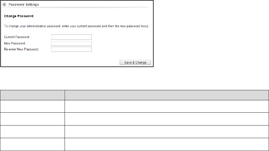
82
4.2.3 Password Settings
This settings helps to change password to restrict from unauthorized access.
To change password, please go to “System Configuration” -> “Password Settings” menu.
Fields Description
Current Password Enter the password of the device.
New Password Enter your new password to which you want to change.
Re-enter New Password
For confirmation, enter the new password again.
Save & Change
It saves and changes to New Password.
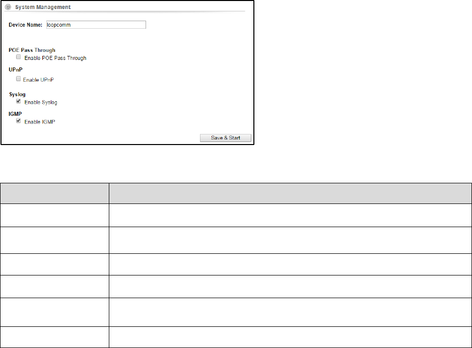
83
4.2.4 System Management
System Configuration -> System Management
In this page, administrator can change the management parameters and disable/enable
management interface.
Fields Description
Device Name Enter the Device Name
POE Pass Through It allows Secondary Ethernet port to provide 24V power for a secondary device when
it’s enabled.
UPnP Administrator can enable or disable the UPnP function
Syslog This option enables the registration routine of system log (syslog) messages.
IGMP Internet Group Management Protocol. Enable/disable the IGMP function for the
multiple bridged ports.
Save & Start It saves the settings and starts.
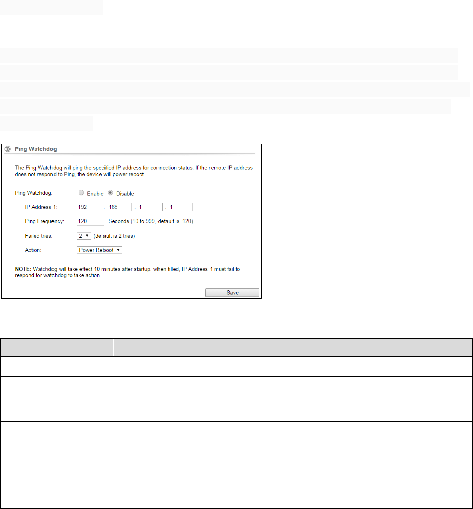
84
4.2.5 Ping Watchdog
System Configuration -> Ping Watchdog
This menu allows to configure system to reboot on kernel panic, when an IP address does not
respond, or in case the system has locked up. Software watchdog timer is used to provide the
last option, so in very rare cases (caused by hardware malfunction) it can lock up by itself. There
is a hardware watchdog device available in all Router BOARD PowerPC which can reboot the
system in any case.
Fields Description
Ping Watchdog Enable/Disable the function to access
IP Address 1 Enter the IP address to be pinged.
Ping Frequency Set the number of seconds to be Pinged.
Failed Tries
Enter the number of permitted times for the ping to be failed before power reboot.
For example "2" means the CPE will reconnect if the PING doesn't respond for
120Seconds.
Action
If the remote IP address does not respond to Ping the device will power reboot.
Save
It saves the changed settings.
When you set the Ping Frequency to every "120" seconds and Fail Tries to "2". It means the User
will ping every 120 seconds, after the second failure, it will reconnect.
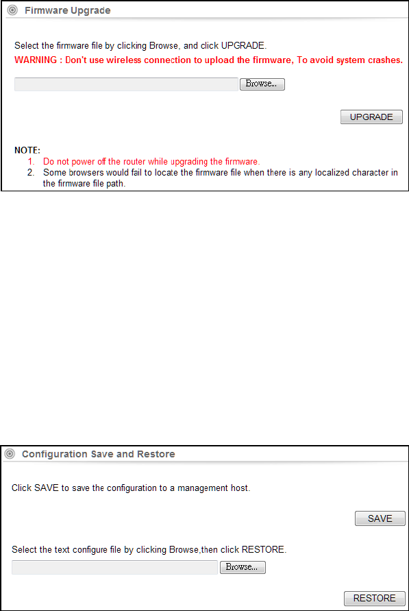
85
4.2.6 Firmware Upgrade
System Configuration -> Firmware Upgrade
Upgrade the device firmware to obtain new functionality. It takes about 1minute to upload new
version. Click the Browse button to select the path and filename for the firmware, and then
click the UPGRADE button to upgrade firmware.
Note: Please do not off the power or remove the Ethernet cable connected to LP-2396K when
firmware upgrade is in process. Otherwise, it will probably cause system crash.
Caution! A corrupted file will hang up the System
4.2.7 Save and Restore
System Configuration -> Configuration Save and Restore
You can save system configuration settings to a file, and later download it back to the LP-2396K
by following the steps.
Save: Press Save button to save the current configuration settings of the device to the
Management Host or click the Browse button to locate the configuration file,
Restore: click the RESTORE button to restore the system configuration from the specified file.
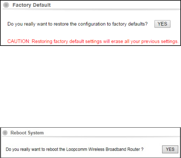
86
4.2.8 Factory Default
System Configuration -> Factory Default
This Feature is used to reset the current configuration setting to the factory default
configuration settings.
Click YES to go ahead and restore the configuration to the factory default.
4.2.9 Reboot
Whenever you use the Web configuration to change system settings, the changes are initially
placed in temporary storage. These changes will be lost if the device is reset or turn off.
IMPORTANT! Do not turn off or press the Reset button while this procedure is in progress.
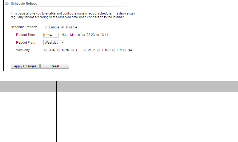
87
4.2.10 Schedule Reboot
Fields Description
Schedule Reboot Enable/Disable the feature to access
Reboot Time
Enter the Time to reboot
Reboot Plan Select the option weekday or every day to reboot
Weekday Select the number of days to reboot
Apply changes
Reset
Click it to save the changed settings
Click it to erase the saved settings.
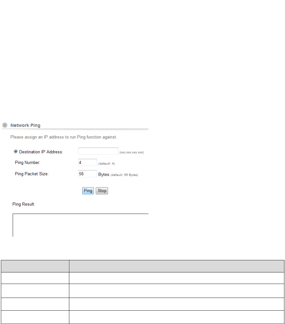
88
4.3 Tools
There are two features in Tools they are Network Ping & Network Traceroute
4.3.1 Network Ping
Network Ping is used to provide a basic connectivity test between the requesting host and a
destination host. This is done by using the Internet Control Message Protocol (ICMP) which has
the ability to send an echo packet to a destination host and a mechanism to listen for a
response from this host. Simply stated, if the requesting host receives a response from the
destination host, this host is reachable. Network Ping is commonly used to provide a basic
picture of where a specific networking problem may exist. For example, if an Internet
connection is down at an office, the ping utility can be used to figure out whether the problem
exists within the office or within the network of the Internet provider.
Fields Description
Destination IP Address Enter the IP address to be Pinged.
Ping Number Number of times to be pinged.
Ping Pack Size Ping Data packet size.
Ping Result It displays the result
Ping: Click it to start to ping.
Stop: Stop the ping.
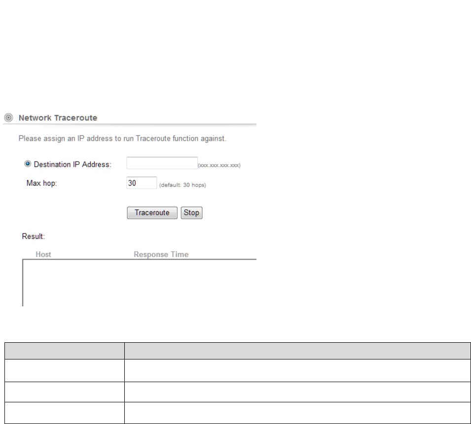
89
4.3.2 Network Traceroute
Once the Network Ping has been used to determine basic connectivity, the Network traceroute
can used to determine more specific information about the path to the destination host
including the route the packet takes and the response time of these intermediate hosts. If you
execute the Traceroute command on a source device, it sends IP packets toward the destination
with Time To Live (TTL) values that increment up to the maximum specified hop count. This is 30
by default on most systems.
Fields Description
Destination IP Address
Enter the IP address to which you like to know the trace route.
Max Hop Maximum number of routes.
Result It displays the result
Traceroute: Click it to trace the route.
Stop: Stop the Traceroute.
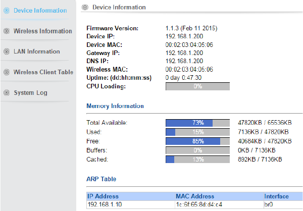
90
4.4 Device Status
Click on the “Device Status” on the top menu bar,
It is used to monitor the status of the device. It provides information on device status, wireless
information, LAN Information, wireless client table and system log.
4.4.1 Device Information
Device Status Device Information
It presents the status of LP-2396K Firmware devices, memory utilization and ARP Table.
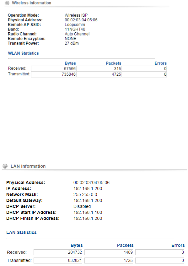
91
4.4.2 Wireless Information
This page shows the wireless information of LP-2396K device, such as current operation mode,
wireless traffic, error packets, device SSID, Band, channel, and encryption used, Transmit Power.
4.4.3 LAN Information
This page shows the LAN information of LP-2396K device, such as Physical Address, IP Address,
Network Mask, Default Gateway and DHCP details.
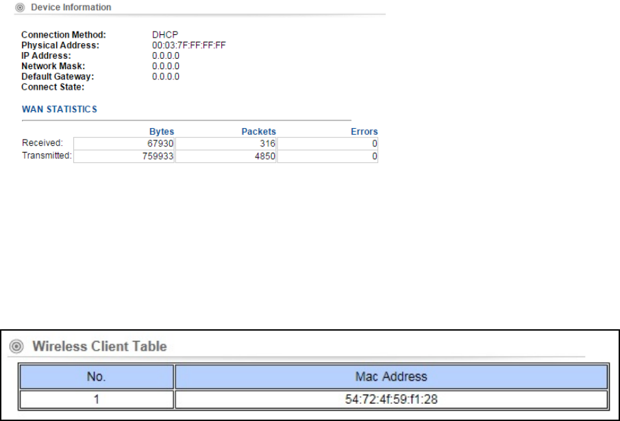
92
4.4.4 Internet Information
4.4.5 Wireless Client Table
This feature displays the currently connected MAC address of Wi-Fi clients
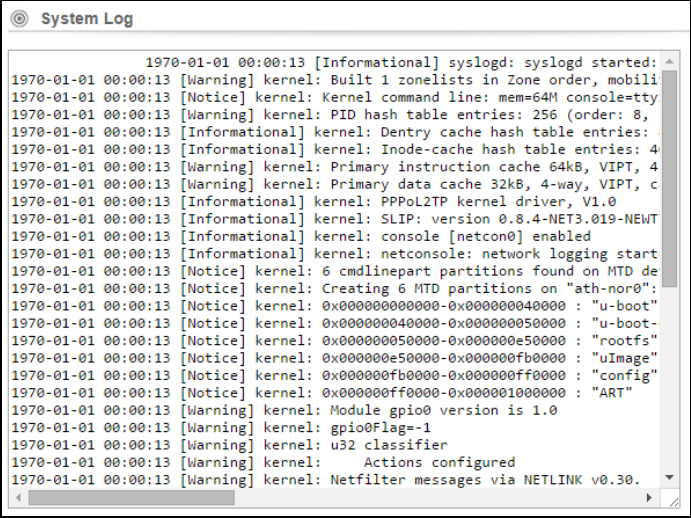
93
4.4.6 System LOG
This page is used to view system logs. The System Log displays the system activities, login, and
system error report.
4.5 LOGOUT
Please make sure to Logout after you finish all settings.
94
5.Compliance
Federal Communication Commission Interference Statement
This equipment has been tested and found to comply with the limits for a Class B digital device,
pursuant to Part 15 of the FCC Rules. These limits are designed to provide reasonable protection
against harmful interference in a residential installation. This equipment generates, uses, and
can radiate radio frequency energy and, if not installed and used in accordance with the
instructions, may cause harmful interference to radio communications. However, there is no
guarantee that interference will not occur in a particular installation. If this equipment does
cause harmful interference to radio or television reception, which can be determined by turning
the equipment off and on, the user is encouraged to try to correct the interference by one or
more of the following measures:
• Reorient or relocate the receiving antenna.
• Increase the separation between the equipment and receiver.
• Connect the equipment into an outlet on a circuit different from that to which the receiver is
connected.
• Consult the dealer or an experienced radio/TV technician for help.
FCC Caution:
This device complies with Part 15 of the FCC Rules. Operation is subject to the following two
conditions: (1) This device may not cause harmful interference, and (2) this device must accept
any interference received, including interference that may cause undesired operation.
RF Radiation Exposure and Hazard Statement:
To ensure compliance with FCC RF exposure requirements, this device must be installed in a
location such that the antenna of the device will be greater than 0.25m away from all persons.
Using higher gain antennas and types of antennas not covered under the FCC certification of
this product is not allowed. Installers of the radio and end users of the product must adhere to
the installation instructions provided in this manual. This transmitter must not be co-located or
operating in conjunction with any other antenna or transmitter.
Non-modification Statement:
Use only the integral antenna supplied by the manufacturer when operating this device.
Unauthorized antennas, modifications, or attachments could damage the TI Navigator access
point and violate FCC regulations. Any changes or modifications not expressly approved by the
party responsible for compliance could void the user's authority to operate this equipment.
Copyright © 2014 Loopcomm Technology Inc. All rights reserved.