Lorex Technology LW2277 2.4G wireless camera product User Manual
Lorex Technology Inc. 2.4G wireless camera product
user manual
LW2277
Version 1.0
USER’S GUIDE
WIRELESS SECURITY CAMERA
WITH AUDIO
LW2277
ENGLISH FRANÇAIS ESPAÑOL
Safety Precautions
• Read this guide carefully and keep it for future
reference.
• Follow all instructions for safe use of the product and
handle with care.
• Use the camera within given temperature,
humidity, and voltage levels noted in the Technical
Specifications.
• Do not disassemble the camera.
• Do not point the camera directly towards the sun or a
source of intense light.
• For outdoor use, installation in a sheltered location is
recommended.
• Periodic cleaning may be required. Use a damp cloth
only. Do not use harsh cleaners or aerosol cleaners.
• Power supply cords should be routed so that they are
not likely to be walked on or pinched by items placed
upon or against them, paying particular attention to
cords at plugs.
• Slots and openings in the case are provided for
ventilation to ensure reliable operation of the video
product and to protect it from overheating. These
openings must not be blocked or covered.
• Do not use attachments unless recommended in the
instructions as they may cause a hazard.
• The cameras provided with this system should be
mounted to a wall or ceiling only as instructed in this
guide, using the provided mounting brackets.
• Never push objects for any kind into this video product
through openings.
• Never spill liquid of any kind on the video product.
• It is recommended to use a surge protector with this
video product.
• The wireless receiver is not weatherproof. Install the
receiver in an indoor location only.
Legal Notice Regarding Audio Recording
Audio recording without consent is illegal in certain
jurisdictions. Lorex Technology Inc. assumes no liability
for use of its products that does not confirm with local
laws.

1
ENGLISH
Product Includes ..............................2
Wireless Receiver ............................3
Wireless Camera .............................4
Installing the Camera ......................5
Installation Tips & Warnings .....................5
Mounting Positions ..................................5
To Install the Camera ............................... 6
Connecting to a DVR .......................8
Connecting to a TV ..........................9
On-Screen Display .........................10
Pairing Cameras ...........................11
Appendix A:
Technical Specifications .................12
Camera ...............................................12
Receiver ...............................................12
Dimensions ...........................................13
Appendix B:
Frequently Asked Questions ..........14
Appendix C: Extending
Wireless Signal Range ...................17
Appendix D: Troubleshooting ........19
Need Help? ...................................19
Table of Contents:
2
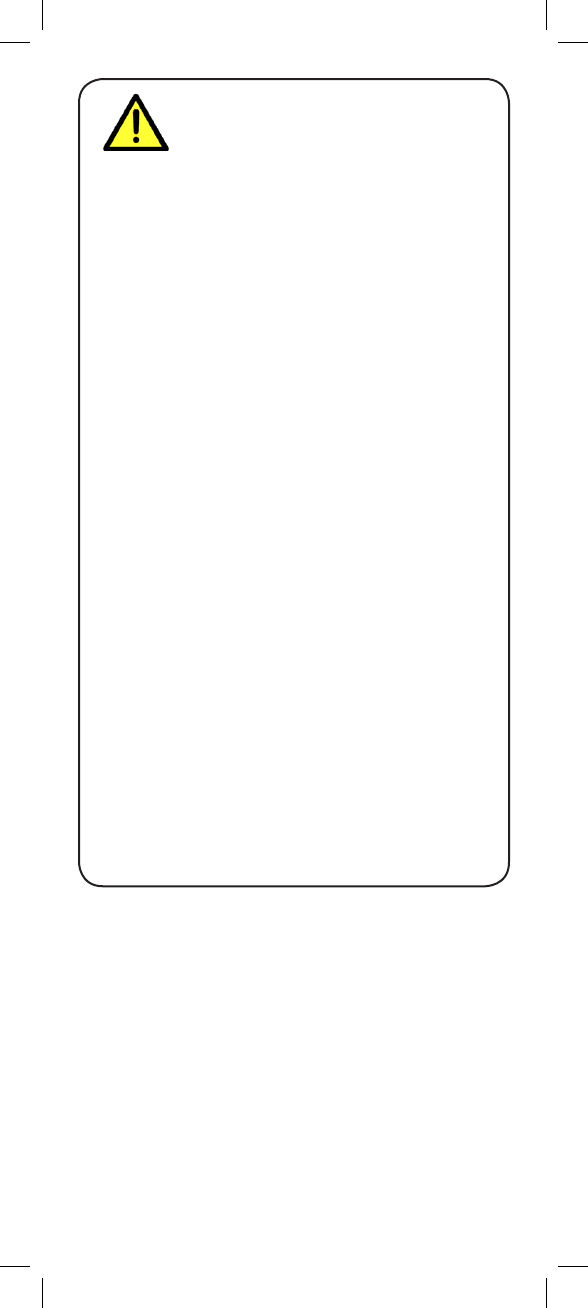
Product Includes
Power Adapter
x1*
Receiver
x1*
Double-Sided Tape
x1*
* Number of cameras and receivers may vary by model.
Camera Power Adapter
x3*
x3*
x1*
Screws & Anchors
x1*
RCA-to-BNC Adapter
x1*
Check your package to confirm that you have received
the complete system, including all components shown
below.
3
ENGLISH
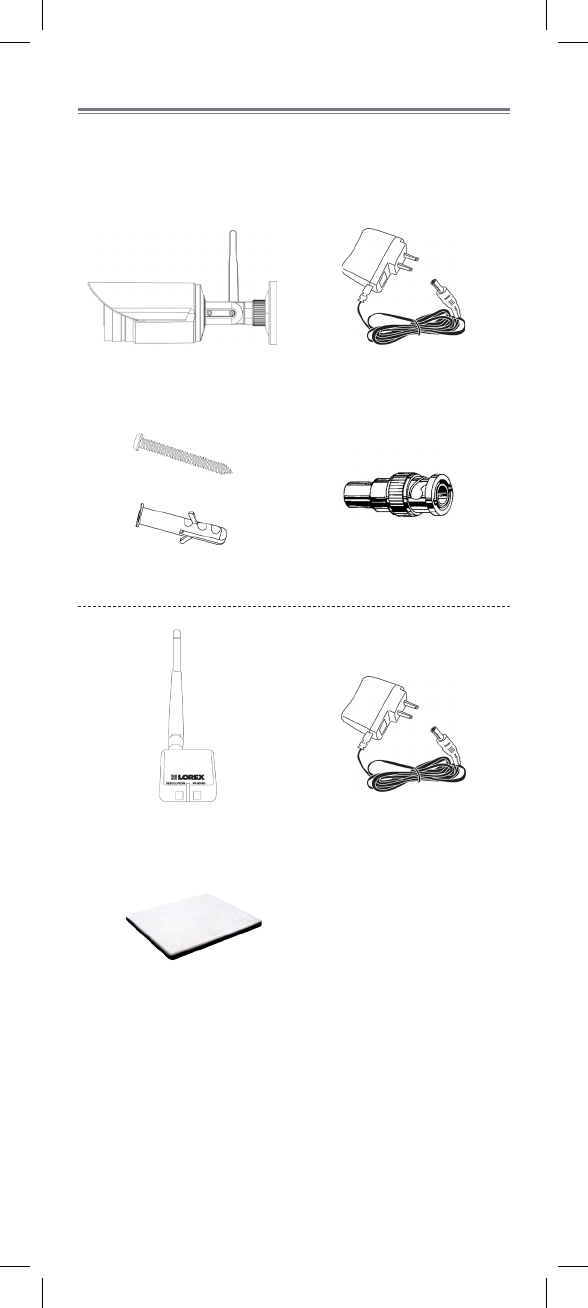
Wireless Receiver
2
1
5
4
3
6
Removable Wireless Antenna (SMA):
Connects to antenna jack on the
back of the receiver.
1. VGA mode has a resolution of 640 X 480 pixels; QVGA
mode has a resolution of 320 X 240 pixels. Use VGA mode
for best video performance. Use QVGA mode for a higher
video frame rate.
1
23 4
Front LED:
Glows green to indicate the
receiver is powered on.
Pairing button:
For details, see See “Pairing
Cameras” on page 11.
Termination cable:
Contains power, RCA video,
and RCA audio connectors.
Antenna jack:
Connection point for the
wireless antenna.
56
6
Resolution button:
Press to switch between VGA
and QVGA resolution1.
4
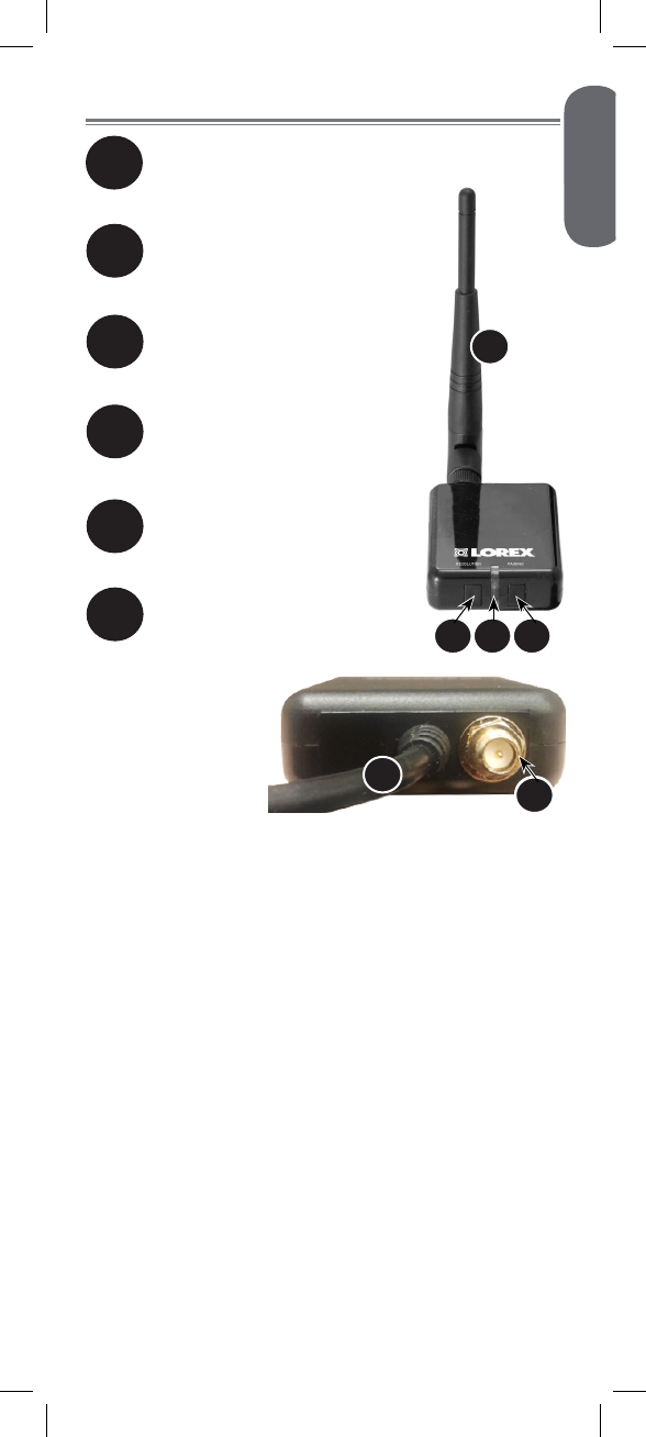
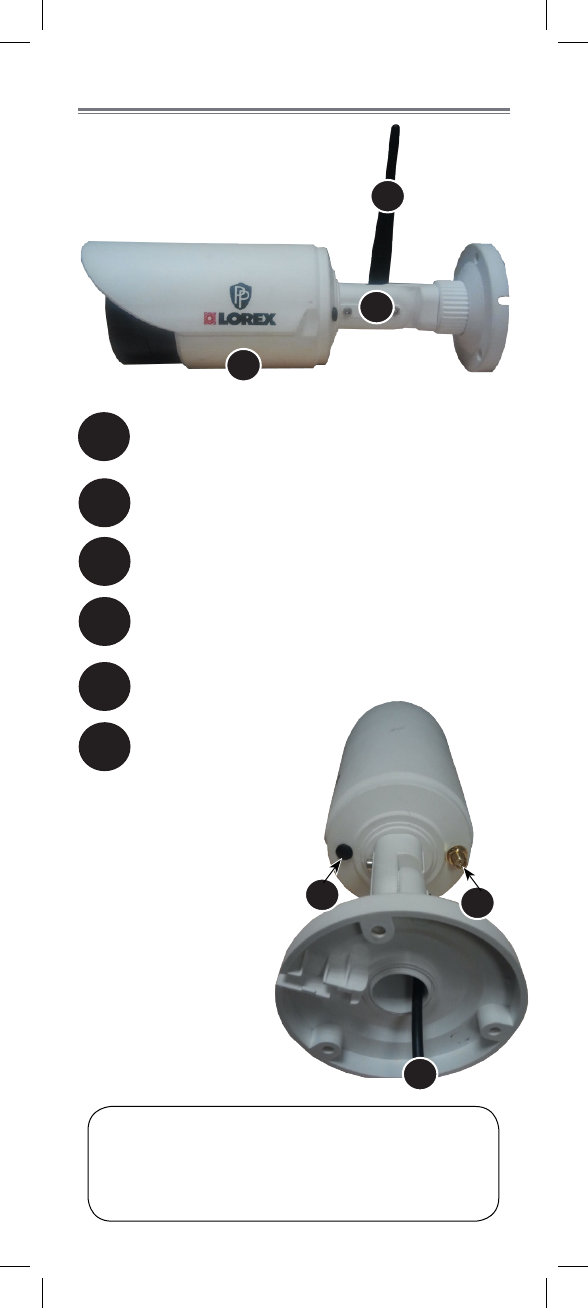
Wireless Camera
2
1
6
5
4
Removable Wireless Antenna (SMA):
Connects to antenna jack on the back of the
camera.
Camera stand
Pairing button:
For details, See “Pairing Cameras” on page
11.
AC Power Cable
Antenna jack:
Connection point for
the wireless antenna.
1
6
6
4
5
2
ATTENTION: This camera includes an Auto Mechanical
IR Cut Filter. When the camera changes between Day/
Night viewing modes, an audible clicking noise may
be heard from the camera. This clicking is normal and
indicates that the camera filter is working.
3Microphone
3
5
ENGLISH
Pairing button:
For details, See “Pairing Cameras” on page
11.
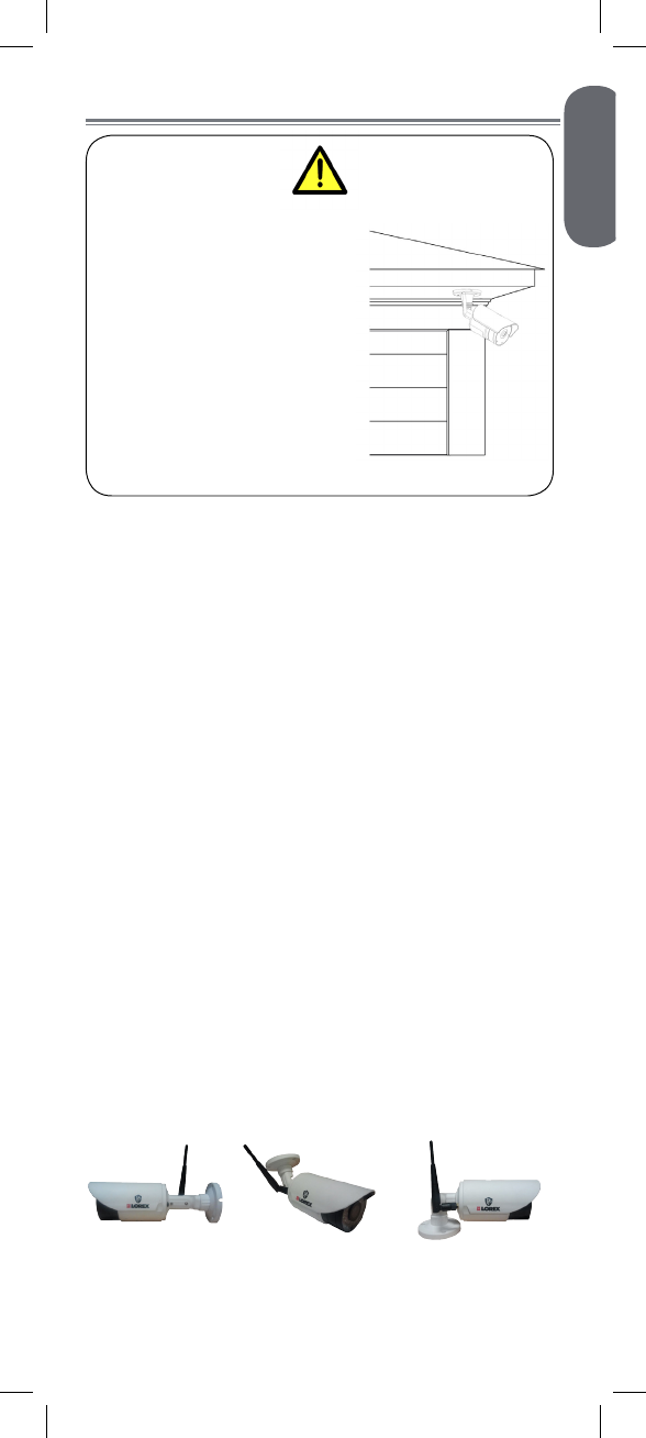
Installing the Camera
Cameras are suitable for
outdoor installation.
Installation in a sheltered
location is recommended.
For example, install under
shelter protected from the
elements, such as beneath
roof eaves. The diagram to
the right shows an example
of an ideal location for
outdoor placement.
Installation Tips & Warnings
• Aim the cameras to best optimize the viewing area:
select a location for the camera that provides a clear
view of the area you want to monitor.
• Install camera in an area that is free from dust, and
that is not in line-of-sight to a strong light source or
direct sunlight.
• Avoid installing the camera where there are thick
walls or obstructions between the camera and the
receiver.
• Avoid installing in a location which requires the
wireless signal to pass through cement, concrete,
and metal structures. This will reduce the range of
transmission. For details, s See “Appendix B:
Frequently Asked Questions” on page 14.
• Select a location for the camera that has an ambient
temperature between 14°F ~ 122°F (–10°C ~ 50°C).
• Not intended for submersion in water. For
outdoor use, installation in a sheltered location is
recommended.
Mounting Positions
You may mount your camera on a wall, ceiling, or
counter. See the images below for recommended
configurations of the camera stand and antenna.
WALL CEILING COUNTER
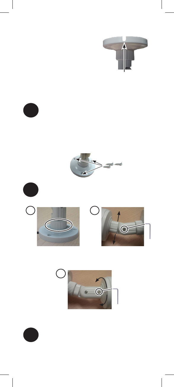
6
2Adjust the position and angle of the camera
until the desired view is set:
B) Loosen lower screw with the
included Allen key to adjust the
camera’s vertical position.
C) Loosen upper screw with the
included Allen key to rotate the
camera housing.
A) Turn the adjustment ring
to tighten / loosen the stand
connection. Adjust the camera’s
horizontal position.
A B
C
To Install the Camera
1
3Screw the antenna to the back of the camera.
Use the included mounting screws to mount the
camera to the mounting surface:
• Mark the position of the screw holes on the wall.
• Drill holes and insert the drywall plugs (included)
as needed.
• Firmly attach the stand to the wall using the
provided screws.
Cable Notch
NOTE: Before you begin,
decide whether to run the
power cable through the wall /
ceiling (drilling required)
or along the wall / ceiling.
If you run the cable
along the wall / ceiling,
you must run it through the cable notch on
the base. This will keep the camera base flush to the
surface when mounted.
7
ENGLISH
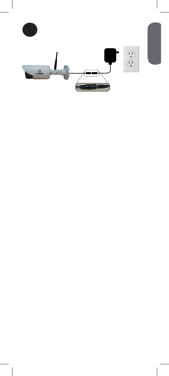
4Connect the power cable from the camera to
the power adapter. Plug the power adapter
into a power outlet or surge protector.
8
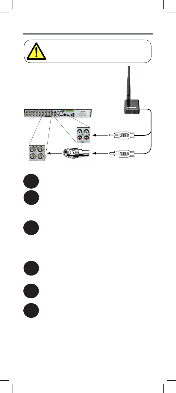
Connecting to a DVR
Before powering on the receiver, make sure
to first connect and power on the camera.
This will ensure a proper connection.
2
1Screw the antenna to the back of the receiver.
Connect the RCA-to-BNC adapter (included)
to the yellow video cable. Connect the yellow
video cable to a BNC video input on your
recording device.
4Connect the power cable to the power
adapter. Plug the power adapter into a power
outlet or surge protector.
5Place the receiver in a place that will have
clear reception to your camera1.
6OPTIONAL: Use the included double-sided
tape to attach the wireless receiver to a flat
surface (e.g. a desk or a wall).
1. Avoid installing in a location which requires the wireless
signal to pass through cement, concrete, and metal structures.
This will reduce the range of transmission.
NOTE: The audio input number or name should
match the video input where you connect the video
input (e.g. Video Input 1 and Audio Input 1).
VIDEO (yellow)
AUDIO (white)
Connect the white audio input cable to an
audio input on your recording device.
3
9
ENGLISH
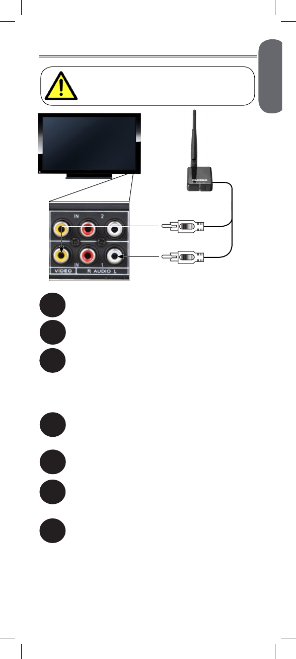
Connecting to a TV
Before powering on the receiver, make sure
to first connect and power on the camera.
This will ensure a proper connection.
2
1Screw the antenna to the back of the receiver.
Connect the yellow video input cable to a
video input on your recording device.
4Connect the power cable to the power
adapter. Plug the power adapter into a power
outlet or surge protector.
6
Place the receiver in a place that will have
clear reception to your camera1.
7
OPTIONAL: Use the included double-sided
tape to attach the wireless receiver to a flat
surface (e.g. a desk or a wall).
1. Avoid installing in a location which requires the wireless
signal to pass through cement, concrete, and metal structures.
This will reduce the range of transmission.
NOTE: The audio input number or name should
match the video input (e.g. Video Input 1 and Audio
Input 1).
VIDEO (yellow)
AUDIO (white)
5
Power on your television and select the input
that the receiver is connected to.
Connect the white audio input cable to an
audio input on your recording device.
3
10
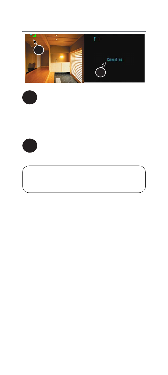
On-Screen Display
1
2
2
1Signal indicator:
The signal indicator shows the strength of the
signal being received from the camera. The
number of bars in the signal indicator shows
the strength of the signal. One or no bars
indicates the signal is poor. Four bars indicate
a very strong signal.
Status indicator:
The message “Connecting” appears when the
receiver is trying to locate a camera.
ATTENTION: If the signal is low (e.g. 1 or 2 bars) adjust
the antennas or reposition the camera or receiver to
improve signal strength.
11
ENGLISH
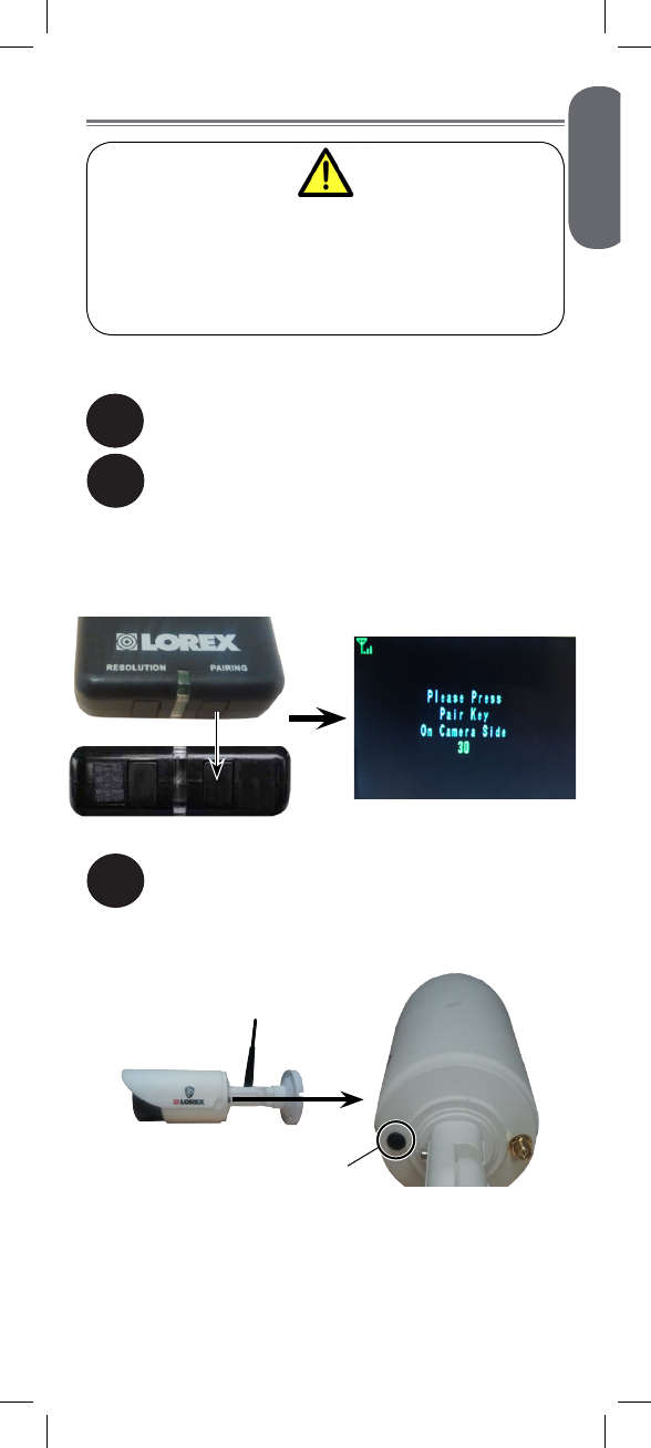
Pairing Cameras
The camera and receiver have already been
pre-paired out of the box, which means that they
are exclusively communicating with each other.
If for some reason the pairing is lost, follow these
steps to pair up the camera and receiver.
To pair the camera to the receiver:
2
1Make sure that the camera and receiver are
both powered up.
On the receiver, press and hold the PAIRING
button for 5 seconds to activate the pairing
function.
• The on-screen displays informs you that you
have 30 seconds to press the pair button on the
camera.
3Press the black pair button on the back of the
camera. You must press the pair button on
the camera within 30 seconds of pressing the
PAIRING button on the wireless receiver.
Pair button
If pairing is successful, live video from the camera will
immediately appear on the monitor.
12
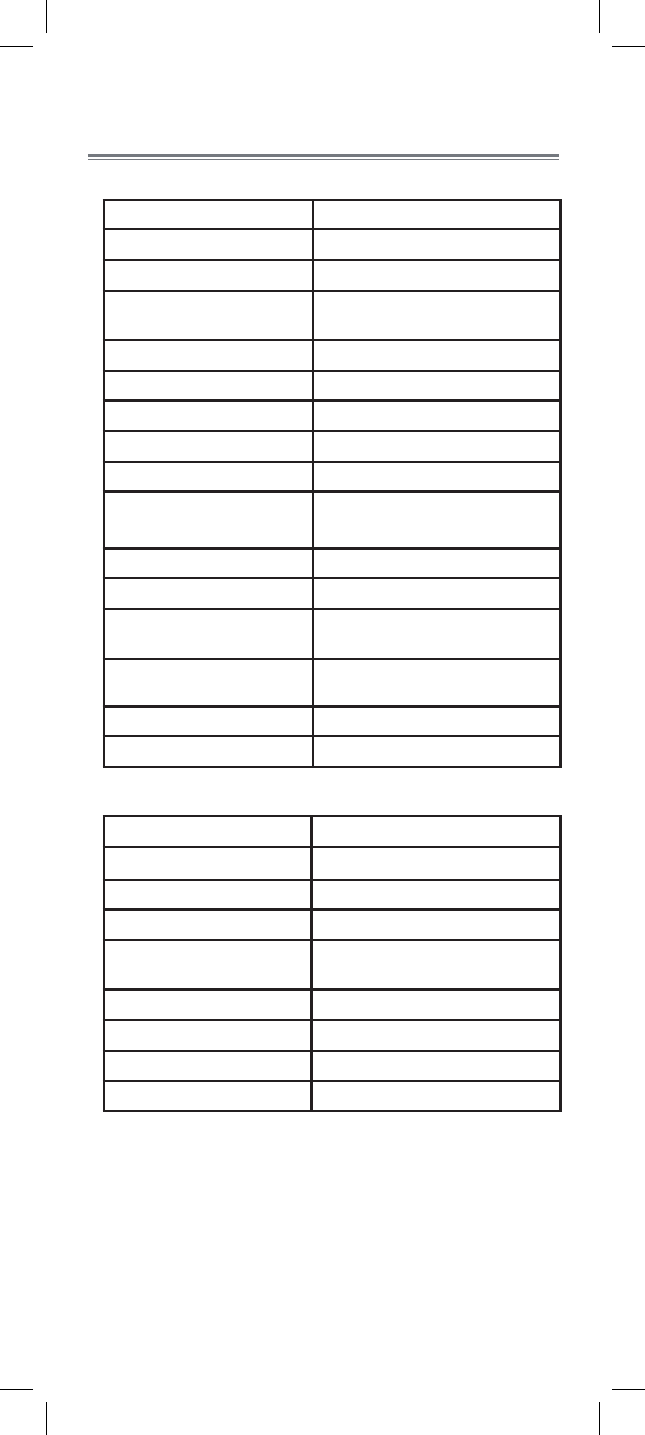
Appendix A:
Technical Specifications
Camera
Frequency 2.400~2.480GHz
TX Power 16dBm
AGC On
Maximum Range Up to 500ft / 150m outdoors*
Up to 165ft / 50m indoors*
Image Sensor 1/4” Color CMOS
Effective Pixels H: 640, V: 480
Lens 4.5mm F1.5
Field of View (Diagonal) 68º
AES Shutter Speed 1/60 ~ 1/62,500
Night Vision Range1Up to 140ft (43m) / 100ft (30m)
IR LED 18 pcs
Power Adapter 12.0V DC 500mA
Power Consumption 455mA Max with IR LED
130mA Max without IR LED
Operating Temperature
Range 14°F ~ 122°F (–10°C ~ 50°C)
Indoor / Outdoor Both (IP66)
Weight 0.6lbs / 0.3kg
Receiver
Frequency 2.400~2.480GHz
RX Sensitivity -81dBm
Demodulation GFSK
Data Rate 160Kb/s
Supported Resolution VGA (640 x 480) up to 12 FPS2
QVGA (320 x 240) up to 30 FPS
Termination 1x RCA video, 1x RCA audio
Power Adapter 12.0V DC 500mA
Power Consumption 130mA Max
Weight 0.2lbs / 0.1kg
*Based on unobstructed line of sight. Actual range will vary
based on surroundings.
1. Stated IR illumination range is based on ideal conditions
in typical outdoor night time ambient lighting and in total
darkness. Actual range and image clarity depends on
installation location, viewing area and light reflection /
absorption level of object.
2. Frames Per Second.
13
ENGLISH
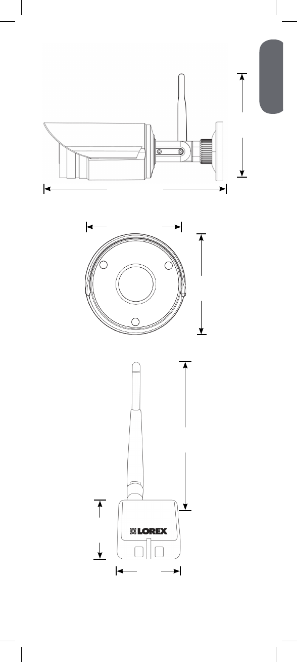
Dimensions
8.9” / 225mm
2.8” / 71mm
2.9” /
74mm
2.3” /
57mm
1.8” /
44mm
5.3” /
135mm
4.5” /
114mm

14
Appendix B:
Frequently Asked Questions
What are the differences between wired
and wireless cameras?
Does a wireless camera require power?
How far can a wireless camera transmit
a video signal?
A wired camera has a video cable that transmits
the video signal from the camera to a recording or
viewing device.
A wireless camera does not use a video cable.
Instead, it wirelessly transmits the video signal to a
wireless receiver that is connected to your recording
or viewing device. Although the typical digital wireless
camera is priced slightly higher than a wired camera,
wireless cameras can provide cost savings compared
to standard wired setups. For example, wireless
cameras do not require cabling to be run between the
camera and the viewing / recording device, which
reduces installation time and cost.
Yes. Wireless cameras require two power sources: one
connected to the camera, and the other to the receiver.
In an open field (with line of sight), a typical wireless
camera has a range between 250 to 500ft. In a
closed environment—such as an interior of a house—
the wireless camera range is between 100 to 165ft
The signal range varies depending on the type of
building materials and/or objects the wireless signal
must pass through.
Cubical walls, drywall, glass, and windows generally
do not degrade wireless signal strength. Brick,
concrete floors, and walls degrade signal strength.
Trees that are in the line of sight of the wireless camera
and receiver may impact signal strength.
The signal range also depends on whether there are
competing signals using the same frequency as the
camera. For example, signals from cordless phones or
routers may affect signal strength.
Range Limiting Factors1
Reflection Scattering Refraction Diffraction Attenuation
The signal
reflects back The signal scatters
back into multiple
new signals
The signal bends
as it travels
through an
object (e.g.
glass window)
The signal
changes direction
as it passes
around an object
The signal
strength weakens
as it passes
through an object
1Source: Xirrus (2010). “Wi-Fi Range Dynamics”.
Retrieved online at http://xirrus.gcsmarket.com/pdfs/
Xirrus_Wi-Fi_Range.pdf
15
ENGLISH
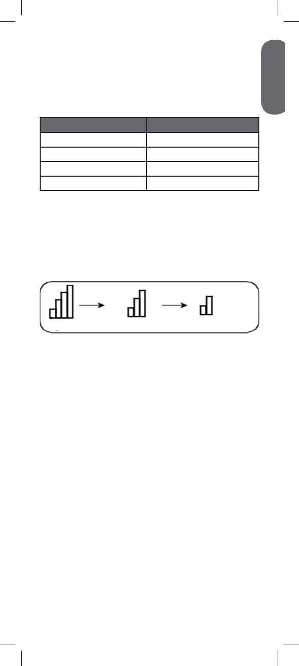
Are digital wireless camera signals secure?
Signal strength decreases as it passes through different
types of material. Try to position your wireless camera
and receiver in a location where the signal does not
pass through metal or concrete blocks, which can
significantly reduce signal strength (as shown in the
table below).
Material Signal Reduction (%)
Plaster & Wood 10 - 30%
Brick 30 - 50%
Concrete Cinder Blocks 50 - 70%
Metal & Metal Cladding 70 - 90%
NOTE: Signals that must pass through wet or moist
materials (e.g. shrubs and trees) may be significantly
reduced.
The stronger the signal strength, the higher the video
frame rate. The lower the signal strength, the lower the
video frame rate.
Yes. Lorex digital wireless products feature a wireless
transmission method called Frequency Hopping
Spread Spectrum (FHSS). This type of signal is highly
resistant to eavesdropping as it generates a channel
hopping sequence using an algorithm generated by
the receiver, which only the camera can follow through
the “pairing” function.
Pairing is an electronic handshake between digital
wireless devices. Digital wireless cameras can only be
paired to one receiver. This is to prevent interception
by third parties, and prevents any other device from
picking up the signal—this also means that you cannot
pair one camera to multiple receivers.
How many wireless cameras can I
install?
It is recommended to install a maximum of 4 wireless
cameras per system (4 receivers and 4 cameras).
Minimum space between receivers should be
2ft / 0.6m and minimum space between cameras
should be 6.5ft / 2m to minimize potential signal
strength degradation.
Reflection Scattering Refraction Diffraction Attenuation
The signal
strength weakens
as it passes
through an object
1Source: Xirrus (2010). “Wi-Fi Range Dynamics”.
Retrieved online at http://xirrus.gcsmarket.com/pdfs/
Xirrus_Wi-Fi_Range.pdf
Full Signal Strength Low Signal Strength
(high frame rate) (low frame rate)

16
How many frames per second should I
expect from a digital wireless camera?
Current Lorex digital wireless cameras offer 10 - 30
FPS (Frames Per Second) performance. Actual frame
rate depends mainly on signal strength (see the chart
in section above).
For details on supported resolutions and frame rates
for this model, s See “Appendix A:
Technical Specifications” on page 12.
17
ENGLISH
Appendix C: Extending
Wireless Signal Range
DISCLAIMER: Certain accessories
are not available in all markets.
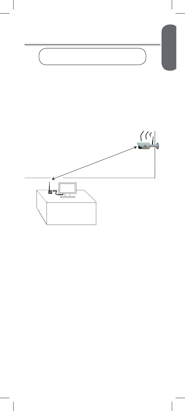
There are several ways to boost your wireless signal
as well as options to help you extend the range of the
wireless signal.
The digital wireless signal is virtually interference free.
However, you should always ensure there is a clear
line-of-sight between the camera and the receiver.
Clear Line-of-Sight
There should be little to no obstacles obstructing the
line-of-sight between the camera and the receiver. Solid
objects, such as concrete and metal, may limit the
range of the wireless signal.
Obstacles
Even with a clear line-of-sight between your camera(s)
and your receiver, you may experience a lower video
frame rate simply due to the distance between your
wireless devices.
Accessory antennas are available that can help extend
the range of your wireless signal.
Extending Your Wireless Signal
Receiver
Clear line-of-sight
18
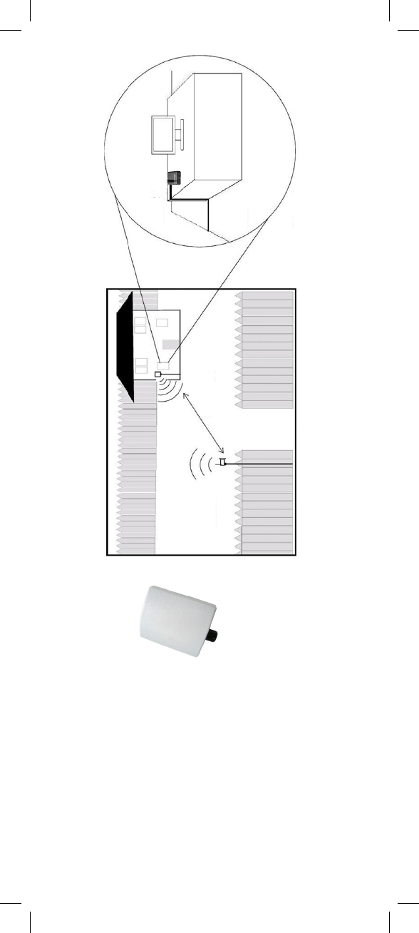
2.4 GHz Directional Wireless
Panel Antenna
Use the 2.4GHz Directional
Wireless Panel Antenna (model #:
ACCANTD9) to focus a wireless
signal onto the camera in order to
increase range of transmission (clear
line-of-sight between the camera and
the antenna is required). A 20ft extension cable is
included help with proper position of the antenna.
Visit www.lorextechnology.com for more
details on wireless antennas and accessories. Outdoor installation Indoor installation
Wireless receiver
Clear line-of-sight
Directional Panel
Antenna
Wireless Camera
19
ENGLISH
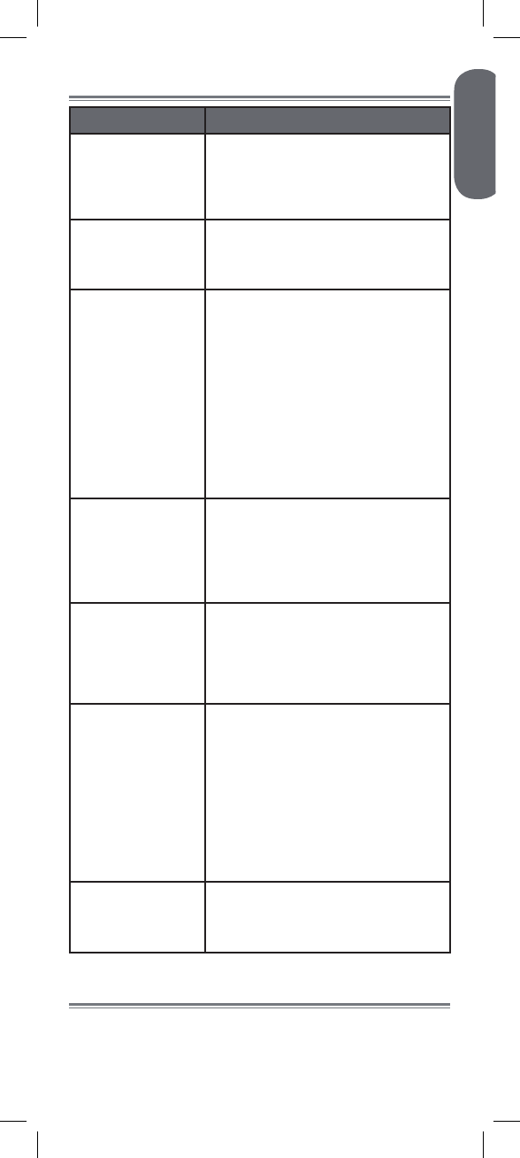
Appendix D: Troubleshooting
Problem Solution
There is no picture
from the camera(s). • Make sure that the camera is plugged
into a power outlet and that the power
adapter is plugged in properly.
• Move the camera closer to the
receiver.
The picture is
dropping. • Move the camera closer to the
receiver.
• Try repositioning the camera, receiver,
or both to improve the reception.
The picture is or has
become choppy. • The picture may become choppy
when experiencing a lower frame rate
(e.g. 6 frames per second vs. a higher
20 frames per second).
• Try moving the camera closer to the
receiver.
• Remove obstructions between the
receiver and camera.
• Try switching to QVGA mode by
pressing the RESOLUTION button
on the receiver. Resolution will be
reduced, but video frame rate will
increase.
There is no audio
from the camera. • Make sure the RCA audio output
cable is connected to your DVR or
television audio input.
• Make sure audio recording is enabled
on your DVR. See your DVR manual
for further instruction.
The picture is white. • “Washout” or “white wash” can occur
when a strong light source is pointed
at the camera lens. The camera lens is
not harmed during a white wash.
• Do not point your camera towards a
bright light source.
The picture appears
fuzzy. • When viewing on a large-screen TV
or monitor (especially high-definition
televisions), the picture might seem
fuzzy as the camera is limited to VGA
resolution (640x480 pixels), while the
TV or monitor supports a much higher
resolution.
• For best performance, use with
TV PIP (Picture in Picture) function.
Check your TV product manual to see
if this feature is available on your TV.
The picture is
pixelated. • You may be in QVGA mode. Try
switching to VGA mode by pressing
the RESOLUTION button on the
receiver.
Product Support is available 24/7 including product
information, user manuals, quick start up guides and
FAQ’s at www.lorextechnology.com/support.
Need Help?

20
CLEANING
Clean the monitor and camera with a slightly damp cloth or an anti-
static cloth. Never use cleaning agents or abrasive solvents.
• Do not clean any part of the product with cleaners with thinners or
other solvents and chemicals. This may cause permanent damage to
the product, which is not covered by the Warranty. When
necessary, clean it with a damp cloth.
• Keep your camera and monitor away from hot, humid areas or
strong sunlight, and do not get it wet.
• Every effort has been made to ensure high standards of reliability
for your baby monitor. However, if something does go wrong,
please do not try to repair it yourself. Contact Customer Service for
assistance.
DISPOSAL OF THE DEVICE
At the end of the product lifecycle, you should not
dispose of this product with normal household waste,
but take the product to a collection point for the
recycling of electrical and electronic equipment. The
symbol on the product, user’s guide, and/or box
indicates this.
Some of the product materials can be re-used if you
take them to a recycling point. By reusing some parts
or raw materials from used products you make an
important contribution to the protection of the environment.
Please contact your local authorities in case you need more information
on the collection points in your area. Dispose of the battery pack in an
environmentally-friendly manner according to your local regulations.
NOTICES
WARNING: Any changes or modifications not expressly approved by
the grantee of this device could void the user’s authority to operate the
device.
FCC NOTICE
This equipment has been certified and found to comply with the limits
regulated by the FCC part 15, subpart C. Operation is subject to
the following two conditions: (1) this device may not cause harmful
interference, and (2) this device must accept any interference received,
including interference that may cause undesired operation. This
equipment has been tested and found to comply with the limits for a
Class B digital device, pursuant to Part 15 of the FCC rules. These
limits are designed to provide reasonable protection against harmful
interference in a residential installation. This equipment generates, uses
and can radiate radio frequency energy and, if not installed and used
in accordance with the instructions, may cause harmful interference to
radio communications.
However, there is no guarantee that interference will not occur in a
particular installation. If this equipment does cause harmful interference
to radio or television reception (which can be determined by turning
the equipment on and off), the user is encouraged to try to correct the
interference by one or more of the following measures:
• Reorient or relocate the receiving antenna
• Increase the separation between the equipment and receiver
• Connect the equipment into an outlet on a circuit different from that
to which the receiver is connected
• Consult the dealer or an experienced radio or television technician
for assistance
CAUTION: To maintain compliance with the FCC’s RF exposure
guidelines, place the camera at least 20cm (7.87in) from nearby
persons.
CANADA/IC NOTICE
This device complies with Industry Canada licence-exempt RSS
standard(s). Operation is subject to the following two conditions: (1)
this device may not cause interference, and (2) this device must accept
any interference, including interference that may cause undesired
operation of the device.