Lorex Technology LW4211-C 1080P AHD/CVI Wireless Camera User Manual 20181018
Lorex Technology Inc. 1080P AHD/CVI Wireless Camera 20181018
Users Manual
Resources
• Ensure your camera is placed as close to your receiver as possible.
• Reduce the number of obstructive materials between the camera and
the receiver. Concrete, brick, metal and wood are the most common
materials in your house that can cause poor signal strength.
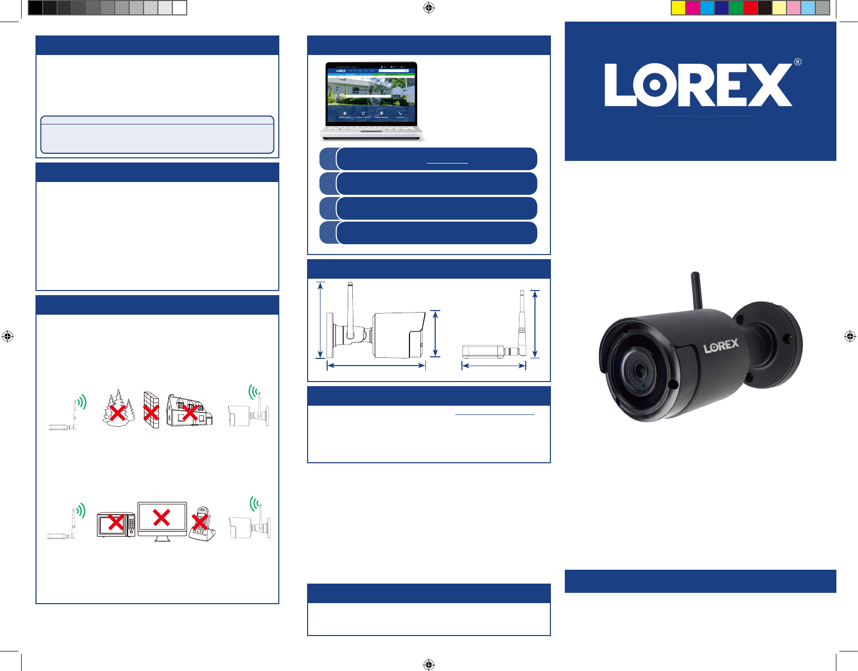
To ensure the best possible wireless performance, it is
recommended to keep the following installation tips in mind
when choosing a location for the camera:
• Point the camera where there is the least amount of obstructions (i.e.,
tree branches).
• Install the camera where vandals cannot easily reach.
• This camera is rated for outdoor use. Installation in a sheltered location
is recommended.
• The camera uses the 2.4GHz band exclusively. Most new routers
support both 2.4GHz and 5GHz bands. It is recommended to use other
WiFi-connected devices using the 5GHz band when possible to ensure
the 2.4GHz band is not overcrowded.
• Other electronic devices such as microwaves, TVs, cordless phones,
and baby monitors can cause signal interference. It is recommended to
install the camera as far away from these devices as possible.
1080p MPX Wireless Security Camera
• 1080p MPX Wireless
Security Camera
• Wireless Receiver
• Antennas (×2)*
• Read this guide carefully and keep it for future reference.
• Follow all instructions for safe use of the product and handle with care.
• Use the camera within given temperature, humidity and voltage levels
noted in the camera’s specifications.
• Do not disassemble the camera.
• Do not point the camera directly towards the sun or a source of
intense light.
• Use only the supplied regulated power supply provided with the
product. Use of a non-regulated, non-conforming power supply can
damage the product and void the warranty.
• Periodic cleaning may be required. Use a damp cloth only. Do not use
any harsh, chemical-based cleaners.
* One each for camera and receiver.
Quick Start Guide
English Version 1.0
LW4211 SERIES
Package Contents
ATTENTION:
A REGULATED UL / CSA APPROVED power supply is REQUIRED for use
with this camera (included). Use of a non-regulated, non-conforming
power supply can damage this product and voids the warranty.
Safety Precautions
Installation Tips
Need Help?
Visit us online for
up-to-date software and
complete instruction
manuals
Click on the Downloads tab
4
Visit lorex.com
Search for the model number
of your product
Click on your product in the
search results
3
2
1
www.lorex.com
Dimensions
5.4” / 138mm
6.1” / 155mm
2.8” / 70mm
4.5” / 114mm
4.4” / 113mm
LW4211_QSG_EN_R1
Copyright © 2018 Lorex Corporation
As our products are subject to continuous improvement, Lorex reserves the right
to modify product design, specifications and prices, without notice and without
incurring any obligation. E&OE. All rights reserved.
• For a full list of compatible recorders, visit lorex.com/compatibility
• Not intended for submersion in water.
• This camera includes an Auto Mechanical IR Cut Filter. When the
camera changes between Day/Night viewing modes, an audible clicking
noise may be heard from the camera. This clicking is normal, and
indicates that the camera filter is working.
Disclaimers
• Power Adapters (×2)*
• Mounting Kits (×2)*
• Allen Key
• BNC Adapter
LW4211_QSG_EN_R1.indd 1 10/10/2018 3:48:50 PM
LW4211_QSG_EN_R1
To install your camera:
Installing the Camera
Cable
Notch
IMPORTANT:
• Test your camera prior to selecting a permanent mounting location by
temporarily connecting the camera and cable to your DVR.
• Ensure the camera is no more than 700ft (213m) away from the wireless
receiver in an open field (with line of sight between antennas). The range
is approximately 115ft (35m) or less in an indoor environment, depending
if there are walls or obstructions between the camera and receiver.
• Review the ‘Installation Tips’ section before choosing a mounting
location for the camera.
Before Installing the Camera
• Decide whether to run the cables through the
wall / ceiling (drilling required) or along the
wall / ceiling.
• If you run the cables along the wall / ceiling,
you must run the cable through the cable
notch on the base. This will keep the camera
base flush to the surface when mounted.
1. Use the included mounting template or camera base to mark
holes for the included mounting screws. Drill holes where
marked.
NOTE: Ensure one of the included antennas is properly
attached to the camera.
2. Mount the camera to the mounting surface using the
included mounting screws (×3).
NOTE: Use the included drywall anchors (×3) if installing
into drywall.
3. Adjust the angle of the camera until the desired view is set.
Tighten the screws to secure the camera position.
Mounting Surface
Camera Base
Drywall Anchors (×3)
Mounting Screws (×3)
4. Connect the camera power adapter to the camera cable.
Connect the power adapter to a power outlet.
5. Remove protective film from the camera lens.
Installing Multiple Wireless Cameras
When installing multiple digital wireless security cameras in the same
environment, maintain at least 4” / 10cm between the receivers to
optimize camera performance.
NOTE: It is not recommended to install more than 3 digital wireless
security cameras in the same environment to maintain optimal video
frame rate performance.
A. Use the included Allen key to
loosen the adjustment screw
on the camera base. Rotate the
arm of the camera up to 360°,
then tighten the screw.
B. Use the included Allen key to
loosen the adjustment screw.
Bend the arm of the camera up
to 90°, then tighten the screw.
C. Use the included Allen key to C
Setting Up the Receiver
1. Ensure one of the included antennas is properly attached to the
receiver.
2. Connect the receiver’s BNC cable to a compatible DVR’s video
input*.
3. Connect the receiver power adapter to the receiver. Connect the
power adapter to a power outlet.
NOTE: Make sure to first connect and power on the camera before
powering on the receiver.
4. (Optional) Use the included double-sided tape to securely attach
the receiver to a flat surface.
(OR)
Secure the receiver to a flat surface using the included mounting
screws.
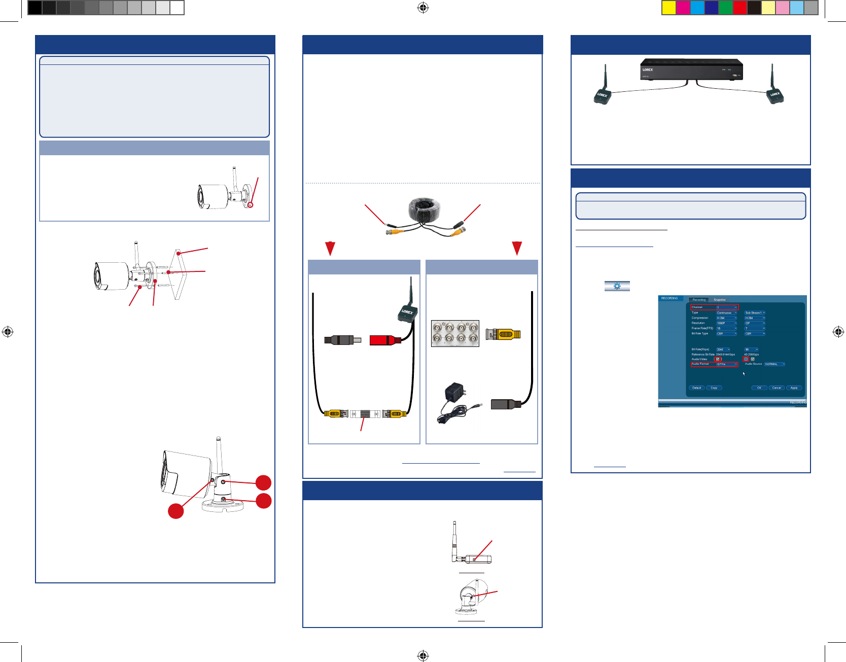
Connecting the receiver directly to DVR:
Connecting the receiver to DVR using a BNC extension cable:
Connect the BNC connector
to a video input on your DVR.
Connect the female power head
to the included receiver power
adapter.
Receiver DVR
Male Power Female Power
**
* This camera is only compatible with select DVRs. For a full list of
compatible recorders, visit lorex.com/compatibility.
** Not included. Compatible BNC extension cable available at lorex.com.
Connect the BNC
connector on the extension
cable to the included
BNC adapter. Connect
the adapter to the BNC
connector on the receiver.
Connect the male power
head to the female
power head on the
receiver.
Audio Settings
ATTENTION:
Audio recording without consent is illegal in certain jurisdictions. Lorex Corporation
assumes no liability for use of its products that does not conform with local laws.
Audio is disabled by default. You can enable audio through a
compatible Lorex DVR. For a full list of compatible recorders, visit
lorex.com/compatibility
NOTE: These instructions are based on current DVR interface. For
the most up-to-date instructions, see your DVR’s instruction manual
on lorex.com.
B
BNC Adapter
Pairing the Camera
The camera and receiver have already been paired out of the box. If for some
reason the pairing is lost, follow these steps to pair the camera and receiver.
Pair Button on
the Camera
To pair the camera and receiver:
Pair Button on
the Receiver
1. Make sure that the camera and receiver are
both powered up and all antennas properly
attached.
2. Press the pair button on the receiver (see
Figure 1).
3. Press and hold the pair button on the back
of the camera within 30 seconds of pressing
the pair button on the receiver (see Figure
2). If successful, live video from the camera
will appear on the monitor.
Figure 1
Figure 2
To enable camera audio on LHV / DV Series DVRs:
1. In Live View, right-click and click Main Menu. Enter the system user
name and password.
2. Click ( ) and select Recording > Recording.
A
loosen the adjustment screw furthest from the camera base. Rotate
the camera until it is level with the viewing area, then tighten the
screw.
3. Under Channel, select
the channel where the
audio-capable camera
is connected.
4. Under Audio/Video,
check the box on the
left to enable audio
recording.
5. Under Audio Format,
select the format
that will be used to
record audio. G711a is
recommended.
6. Click OK to save changes.
7. (Optional) Under Audio/Video, check the middle box to enable audio
when viewing cameras through the computer or mobile applications.
LW4211_QSG_EN_R1.indd 2 10/10/2018 3:48:53 PM
LW4211_QSG_EN_R1.indd 3 10/10/2018 3:48:53 PM
The user is cautioned that changes or modifications not expressly approved by the party responsible for compliance could void the user's authority to operate the equipment.
This device complies with Part 15 of the FCC Rules and Industry Canada licence-exempt RSS standard(s). Operation is subject to the following two conditions: (1) this device may not cause harmful interference, and (
2) this device must accept any interference received, including interference that may cause undesired operation.
Le présent appareil est conforme aux CNR d’Industrie Canada applicables aux appareils radio exempts de licence. L’exploitation est autorisée aux deux conditions suivantes :
(1) l’appareil ne doit pas produire de brouillage, et
(2) l’utilisateur de l’appareil doit accepter tout brouillage radioélectrique subi, même si le brouillage est susceptible d’en compromettre le fonctionnement.
NOTE: This equipment has been tested and found to comply with the limits for a Class B digital device, pursuant to Part 15 of the FCC Rules. These limits are designed to provide reasonable protection against harmful interference in a residential
installation. This equipment generates, uses and can radiate radio frequency energy and, if not installed and used in accordance with the instructions, may cause harmful interference to radio communications. However, there is no guarantee
that interference will not occur in a particular installation.
If this equipment does cause harmful interference to radio or television reception, which can be determined by turning the equipment off and on, the user is encouraged to try to correct the interference by one or more of the following measures:
-- Reorient or relocate the receiving antenna.
-- Increase the separation between the equipment and receiver.
-- Connect the equipment into an outlet on a circuit different from that to which the receiver is connected.
-- Consult the dealer or an experienced radio/TV technician for help.
FCC& IC Radiation Exposure Statement:
This equipment complies with FCC and Canada radiation exposure limits set forth for an uncontrolled environment. This equipment should be installed and operated with a minimum distance of 20cm between the radiator and your body.
This transmitter must not be co-located or operating in conjunction with any other antenna or transmitter.
Déclaration d’IC sur l’exposition aux radiations:
Cet équipement est conforme aux limites d’exposition aux radiations définies par le Canada pour des environnements non contrôlés. Cet équipement doit être installé et utilisé à une distance minimum de 20 cm entre l’antenne et votre corps.
Cet émetteur ne doit pas être installé au même endroit ni utilisé avec une autre antenne ou un autre émetteur.
Caution: