Lorex 8 Channel Security Nvr With Real Time 1080P Recording Owners Manual LNR200 NetHD Series Network Video Surveillance Recorder
Lorex-16-Channel-Security-Nvr-With-Poe-Switch-Owners-Manual lorex-16-channel-security-nvr-with-poe-switch-owners-manual
2014-07-19
: Lorex Lorex-8-Channel-Security-Nvr-With-Real-Time-1080P-Recording-Owners-Manual lorex-8-channel-security-nvr-with-real-time-1080p-recording-owners-manual lorex pdf
Open the PDF directly: View PDF ![]() .
.
Page Count: 195 [warning: Documents this large are best viewed by clicking the View PDF Link!]
- NVR Overview
- Basic Setup
- Step 1: Connect the Mouse
- Step 2: Connect the Ethernet Cable
- Step 3: Connect the Monitor
- Step 4: Connect the Power Adapter and Power on the NVR
- Step 5: Connect the IP Cameras
- Step 6: Verify Camera Image
- Step 7: Set the Time
- Default System Password & Port Numbers
- Quick Access to System Information
- Camera Installation Tips
- Connecting Cameras over the Local Network
- Mouse Control
- Remote Control
- Using the On-Screen Display
- Setting the Date and Time
- Recording
- Playback
- Backing Up Video
- Managing Passwords
- Using the Main Menu
- Manual
- HDD
- Record
- Camera
- Configuration
- Maintenance
- Shutdown
- Connecting to Your NVR Over the Internet on PC or Mac
- Client Software for PC or Mac
- Control Panel
- Main View
- Video Player
- E-Map
- Event Search
- Remote Playback
- Add Camera
- Local Log Search
- Account Management
- Device Management
- Configuring an NVR Through Device Management
- Camera Settings
- Adjusting Picture Settings
- Configuring Video Quality
- Configuring Camera Recording Schedules
- Configuring the Camera Video Display (OSD) and Privacy Masks
- Configuring Motion Detection Settings
- Configuring Tampering Alarm Settings
- Configuring Video Loss Alarms
- PTZ Control (Not Supported)
- Network Connection (Not Supported)
- System Configuration
- Mobile Apps: Accessing your NVR Using a Mobile Device
- Appendix A: System Specifications
- Appendix B: Installing or Replacing the Hard Drive
- Appendix C: DDNS Setup (Advanced)
- Appendix D: Connecting to your NVR Using a Web Browser
- Troubleshooting
- Getting Started
www.lorextechnology.com
NETWORK VIDEO SURVEILLANCE RECORDER
LNR300 netHD Series
Copyright © 2013 Lorex Technology Inc.
Instruction Manual
English Version 1.0
RETAIL INDUSTRY BUSINESS
BUSINESS HOME OUTDOOR
CONNECTIVITY
Thank you for purchasing the Lorex Network Video Surveillance Recorder.
This manual refers to the following models:
• LNR340 (4-channel)
• LNR380 (8-channel)
• LNR360 (16-channel)
For the latest online manual, downloads and product updates, and to learn about our
complete line of accessory products, please visit our website at:
www.lorextechnology.com
CAUTION
RISK OF ELECTRIC SHOCK
DO NOT OPEN
CAUTION: TO REDUCE THE RICK OF ELECTRIC SHOCK DO NOT
REMOVE COVER. NO USER SERVICABLE PARTS INSIDE.
REFER SERVICING TO QUALIFIED SERVICE PERSONNEL.
The lightning flash with arrowhead symbol, within an equilateral
triangle, is intended to alert the user to the presence of uninsulated
"dangerous voltage" within the products ' enclosure that may be of
sufficient magnitude to constitute a risk of electric shock.
The exclamation point within an equilateral triangle is intended to
alert the user to the presence of important operating and
maintenance (servicing) instructions in the literature accompanying
the appliance.
WARNING: TO PREVENT FIRE OR SHOCK HAZARD, DO NOT
EXPOSE THIS UNIT TO RAIN OR MOISTURE.
CAUTION: TO PREVENT ELECTRIC SHOCK, MATCH WIDE BLADE
OF THE PLUG TO THE WIDE SLOT AND FULLY INSERT.

NEED HELP?
CONTACT US FIRST
2 Easy Ways to Contact Us
Please make sure to register your product at www.lorextechnology.com
to receive product updates and technical support.
DO NOT RETURN THIS PRODUCT TO THE STORE
SEP 12 2012 - R14
North America:
Customer Service (for warranty matters): 1-888-425-6739 (1-888-42-LOREX)
Tech Support (for technical/installation issues): 1-877-755-6739 (1-877-75-LOREX)
Mexico: 001-800-681-9263, 001-800-514-6739
International: +800-425-6739-0 (Example: From the UK, dial 00 instead of +)
By Phone:
Online:
For all other matters, visit www.lorextechnology.com
Product Support is available 24/7 including product information, user
manuals, quick start up guides and FAQ’s at
www.lorextechnology.com/support

SEP 12 2012 - R14
¿NECESITA AYUDA?
COMUNÍQUESE PRIMERO
CON NOSOTROS
BESOIN D’ASSISTANCE?
COMMUNIQUEZ D’ABORD
AVEC NOUS
2 façons simples de communiquer
avec nous :
En Amérique du Nord :
Service à la clientèle (pour tout ce qui concerne la garantie) :
1-888-425-6739 (1-888-42-LOREX)
Soutien technique (pour les questions d’ordre technique ou relatives à
l’installation) : 1-877-755-6739 (1-877-75-LOREX)
Mexique : 001-800-681-9263, 001-800-514-6739
International : +800-425-6739-0
(par exemple : à partir du Royaume-Uni, composez le 00 au lieu de +)
Par téléphone :
Veuillez enregistrer votre produit sur le site
www.lorextechnology.com afin de recevoir des mises à jour
et le soutien technique pour votre produit.
Pour toutes les autres questions,
visitez www.lorextechnology.com
À votre disposition 24/7, le soutien pour les produits comprend
les renseignements sur les produits, guides d’utilisation, guides
de départ rapide et FAQ :
www.lorextechnology.com/support
En ligne :
Hay 2 maneras fáciles de comunicarse
con nosotros:
Norte América:
Atención al cliente (para asuntos de la garantía):
1-888-425-6739 (1-888-42-LOREX)
Asistencia técnica (para asuntos técnicos o de instalación):
1-877-755-6739 (1-877-75-LOREX)
Mexico: 001-800-681-9263, 001-800-514-6739
Internacional: +800-425-6739-0
(Ejemplo: Desde el Reino Unido, marque el 00 en lugar del +)
Por teléfono:
Apoyo al cliente está disponible 24/7, incluyendo
información del producto, manuales para el usuario, guías
de inicio rápido y preguntas más frecuentes en:
www.lorextechnology.com/support
En línea:
Por favor, registre su producto en www.lorextechnology.
com para recibir actualizaciones del producto y
asistencia técnica.
Para todo lo demás, visite
www.lorextechnology.com
NO DEVUELVA ESTE PRODUCTO A LA TIENDA NE RETOURNEZ PAS CE PRODUIT AU MAGASIN
VIEW YOUR WORLD™
VOIR VOTRE MONDEMD
VEA SU MUNDO™
SEP 6 2012 - R8
LOREX IS COMMITTED TO FULFILLING YOUR SECURITY NEEDS
• We have developed user friendly products and documentation.
Please read the Quick Start Guide and User Manual before you
install this product.
• Consumer Guides and Video Tutorials are available on our web
site at www.lorextechnology.com/support
• If you require further installation assistance, please visit
www.lorextechnology.com/installation or contact a
professional installer.
• Please note that once the components of this product have been
unsealed, you cannot return this product directly to the store
without the original packaging.
THIS PRODUCT MAY REQUIRE PROFESSIONAL INSTALLATION
BEFORE YOU START
Please make sure to register your product at www.lorextechnology.com
to receive product updates and technical support
SEP 6 2012 - R8
LOREX SE COMPROMETE A SATISFACER
SUS NECESIDADES EN SEGURIDAD
LOREX S’ENGAGE À RÉPONDRE À VOS
BESOINS EN MATIÈRE DE SÉCURITÉ
ESTE PRODUCTO PUEDE EXIGIR UNA IN-
STALACIÓN PROFESIONAL
CE PRODUIT PEUT NÉCESSITER UNE
INSTALLATION PROFESSIONNELLE
• Nous avons conçu et développé une documentation
et des produits extrêmement conviviaux. Veuillez
lire le Guide de départ rapide et le Guide
d’utilisation avant d’installer ce produit.
• Des guides pour consommateurs et des tutoriels
vidéo vous sont offerts sur notre site Web :
www.lorextechnology.com/support
• Si vous avez besoin de plus d’assistance pour
l’installation de ce produit, veuillez visiter le site
www.lorextechnology/installation ou communiquez
avec un installateur professionnel.
• Veuillez prendre note que lorsque vous avez déballé
les pièces et composantes de ce produit, vous ne
pouvez pas retourner celui-ci directement au
magasin sans son emballage original.
• Favor de leer la guía de instalación rápida y la
guía del usuario antes de instalar este product.
• Puede conseguir las guías del consumidor y los
cursos en enseñanza video sobre el Internet
visitando www.lorextechnology.com/support
• Si necesita ayuda para la instalación, visite
www.lorextechnology.com/installation o contacte
un especialista en instalaciones.
• Favor de notar que una vez que los componentes
de este producto han sido removidos del
embalaje, no podrá devolver este producto
directamente a la tienda.
AVANT DE
COMMENCER
ANTES DE
EMPEZAR
www.lorextechnology.com
Veuillez enregistrer votre produit sur le site
www.lorextechnology.com afin de recevoir
des mises à jour et le soutien technique pour
votre produit.
Cerciórese de por favor colocar su producto
en www.lorextechnology.com para recibir
actualizaciones y la información del producto
y soporte técnico.
VIEW YOUR WORLD™
VOIR VOTRE MONDEMD
VEA SU MUNDO™
v
Important Safeguards
In addition to the careful attention devoted to quality standards in the manufacture process of your
product, safety is a major factor in the design of every instrument. However, safety is your
responsibility too. This sheet lists important information that will help to ensure your enjoyment
and proper use of the product and accessory equipment. Please read them carefully before
operating and using your product.
General Precautions
1. All warnings and instructions in this manual should be followed.
2. Remove the plug from the outlet before cleaning. Do not use liquid aerosol detergents. Use a
water-dampened cloth for cleaning.
3. Do not use this product in humid or wet places.
4. Keep enough space around the product for ventilation. Slots and openings in the storage
cabinet should not be blocked.
5. It is highly recommended to connect the product to a surge protector to protect from damage
caused by electrical surges. It is also recommended to connect the product to an
uninterruptible power supply (UPS), which has an internal battery that will keep the product
running in the event of a power outage.
Installation
1. Read and Follow Instructions - All the safety and
operating instructions should be read before the product
is operated. Follow all operating instructions.
2. Retain Instructions - The safety and operating
instructions should be retained for future reference.
3. Heed Warnings - Comply with all warnings on the
product and in the operating instructions.
4. Polarization - Do not defeat the safety
purpose of the polarized or
grounding-type plug.
A polarized plug has two blades with
one wider than the other.
A grounding type plug has two blades
and a third grounding prong.
The wide blade or the third prong are
provided for your safety.
If the provided plug does not fit into your outlet, consult
an electrician for replacement of the obsolete outlet.
5. Power Sources - This product should be operated only
from the type of power source indicated on the marking
label. If you are not sure of the type of power supplied
to your location, consult your video dealer or local power
company. For products intended to operate from battery
power, or other sources, refer to the operating
instructions.
6. Overloading - Do not overload wall outlets or
extension cords as this can result in the risk of fire or
electric shock. Overloaded AC outlets, extension
cords, frayed power cords, damaged or cracked wire
insulation, and broken plugs are dangerous. They may
result in a shock or fire hazard. Periodically examine
the cord, and if its appearance indicates damage or
deteriorated insulation, have it replaced by your
service technician.
7. Power-Cord Protection - Power supply cords should
be routed so that they are not likely to be walked on or
pinched by items placed upon or against them. Pay
particular attention to cords at plugs, convenience
receptacles, and the point where they exit from the
product.
8. Surge Protectors - It is highly recommended that the
product be connected to a surge protector. Doing so
will protect the product from damage caused by power
surges. Surge protectors should bear the UL listing
mark or CSA certification mark.
9. Uninterruptible Power Supplies (UPS) - Because
this product is designed for continuous,
24/7 operation, it is recommended that you connect
the product to an uninterruptible power supply. An
uninterruptible power supply has an internal battery
that will keep the product running in the event of a
power outage. Uninterruptible power supplies should
bear the UL listing mark or CSA certification mark.
Caution: Maintain electrical safety. Power line
operated equipment or accessories connected to this
product should bear the UL listing mark or CSA
certification mark on the accessory itself and should
not be modified so as to defeat the safety features. This
will help avoid any potential hazard from electrical
shock or fire. If in doubt, contact qualified service
personnel.
vi
Installation (Continued)
10. Ventilation - Slots and openings in the case are
provided for ventilation to ensure reliable operation of
the product and to protect it from overheating. These
openings must not be blocked or covered. The
openings should never be blocked by placing the
product on a bed, sofa, rug, or other similar surface.
This product should never be placed near or over a
radiator or heat register. This product should not be
placed in a built-in installation such as a bookcase or
rack unless proper ventilation is provided and the
product manufacturer’s instructions have been
followed.
11. Attachments - Do not use attachments unless
recommended by the product manufacturer as they
may cause a hazard.
12. Water and Moisture - Do not use this product near
water — for example, near a bath tub, wash bowl,
kitchen sink or laundry tub, in a wet basement, near a
swimming pool and the like.
13. Heat - The product should be situated away from heat
sources such as radiators, heat registers, stoves, or
other products (including amplifiers) that produce
heat.
14. Accessories - Do not place this
product on an unstable cart,
stand, tripod, or table. The product
may fall, causing serious damage
to the product. Use this product
only with a cart, stand, tripod,
bracket, or table recommended by
the manufacturer or sold with the
product. Any mounting of the
product should follow the manufacturer’s instructions
and use a mounting accessory recommended by the
manufacturer.
15. Camera Extension Cables – Check the rating of
your extension cable(s) to verify compliance with your
local authority regulations prior to installation.
16. Mounting - The cameras provided with this system
should be mounted only as instructed in this guide or
the instructions that came with your cameras, using
the provided mounting brackets.
17. Camera Installation- Cameras are not intended for
submersion in water. Not all cameras can be installed
outdoors. Check your camera environmental rating to
confirm if they can be installed outdoors. When
installing cameras outdoors, installation in a sheltered
area is required.
Service
1. Servicing - Do not attempt to service this product
yourself, as opening or removing covers may expose
you to dangerous voltage or other hazards. Refer all
servicing to qualified service personnel.
2. Conditions Requiring Service - Unplug this product
from the wall outlet and refer servicing to qualified
service personnel under the following conditions:
A. When the power supply cord or plug is damaged.
B. If liquid has been spilled or objects have fallen into
the product.
C. If the product has been exposed to rain or water.
D. If the product has been dropped or the cabinet has
been damaged.
E. If the product does not operate normally by
following the operating instructions. Adjust only those
controls that are covered by the operating
instructions. Improper adjustment of other controls
may result in damage and will often require extensive
work by a qualified technician to restore the product
to its normal operation.
F. When the product exhibits a distinct change in
performance. This indicates a need for service.
7. Replacement Parts - When replacement parts are
required, have the service technician verify that the
replacements used have the same safety
characteristics as the original parts. Use of
replacements specified by the product manufacturer
can prevent fire, electric shock, or other hazards.
8. Safety Check - Upon completion of any service or
repairs to this product, ask the service technician to
perform safety checks recommended by the
manufacturer to determine that the product is in safe
operating condition.
Use
1. Cleaning - Unplug the product from the wall outlet
before cleaning. Do not use liquid cleaners or aerosol
cleaners. Use a damp cloth for cleaning.
2. Product and Cart Combination - When product is
installed on a cart, product and cart combination
should be moved with care. Quick stops, excessive
force, and uneven surfaces may cause the product and
cart combination to overturn.
3. Object and Liquid Entry - Never push objects of any
kind into this product through openings as they may
touch dangerous voltage points or “short-out” parts
that could result in a fire or electric shock. Never spill
liquid of any kind on the product.
4. Lightning - For added protection of this product
during a lightning storm, or when it is left unattended
and unused for long periods of time, unplug it from
the wall outlet and disconnect the antenna or cable
system. This will prevent damage to the product due
to lightning and power line surges.
NOTICES
FCC/IC Notice:
This equipment has been tested and found to comply with the limits for a Class B digital device, pursuant
to Part 15 of the FCC Rules. These limits are designed to provide reasonable protection against harmful
interference in a residential installation. This equipment generates, uses, and can radiate radio frequency
energy and, if not installed and used in accordance with the instruction, may cause harmful interference
to radio communications.
However, there is no guarantee that interference will not occur in a particular installation. If this
equipment does cause harmful interference to radio or television reception (which can be determined by
turning the equipment on and off), the user is encouraged to try to correct the interference by one or more
of the following measures:
• Reorient or relocate the receiving antenna
• Increase the separation between the equipment and receiver
• Connect the equipment into an outlet on a circuit different from that to which the receiver is connected
• Consult the dealer or an experienced radio or television technician for assistance
Modification:
Any changes or modifications not expressly approved by the grantee of this device could void the user's
authority to operate the device.
Toute modification non approuvée explicitement par le fournisseur de licence de l'appareil peut entraîner
l'annulation du droit de l'utilsateur à utiliser l'appareil.
RoHS:
This product is fully compliant with the European Union Restriction of the Use of Certain Hazardous
Substances in Electrical and Electronic Equipment ("RoHS") Directive (2002/95/EC). The RoHS directive
prohibits the sale of electronic equipment containing certain hazardous substances such as lead,
cadmium, mercury, and hexavalent chromium, PBB, and PBDE in the European Union.
vii
This product has been certified and found to comply with the limits regulated by FCC, EMC, and
LVD. Therefore, it is designated to provide reasonable protection against interference and will not
cause interference with other appliance usage.
However, it is imperative that the user follows the guidelines in this manual to avoid improper
usage, which may result in damage to the product, electrical shock and fire hazard injury.
In order to improve the features, functions, and quality of this product, the specifications are
subject to change without notice from time to time.
www.lorextechnology.com
Product Information
User Manuals
Quick Start Guides
Specification Sheets
Software Upgrades
Firmware Upgrades

viii
Features
Network Video Recorder Features
• FULL HD 1080P Resolution
• Real-time Recording 30fps per channel (4/8 @1080p, 16ch@720p)
• Recording speed @ 1080p (4/8/16 120/240/240fps)
• Simultaneous Playback and Live view on the same screen
• Selectable area Zoom during Live view and Playback
• Easy camera installation using Power over Ethernet (CAT5) cable
• 24/7 100% Duty Cycle Hard Disc Drive
• Expandable High Capacity Storage up to 8TB (max 2x4TB HDD)
• Mirror Hard Drive Recording - secure your recordings by backing up footage to an internal
hard drive at the same time as recording to the primary hard drive1
• HDMI output resolution 1080p & VGA output for simple connection to HDTVs (HDMI cable
included)
• Pentaplex operation - View, Record, Playback, Backup & Remotely control the system
simultaneously
Connectivity Features2
• LOREX Stratus Solution - Quick & simple cloud connectivity
• Instant Mobile Viewing on compatible Smartphones3
• Dedicated iPad® and Android™ tablet apps with multi-channel live viewing and playback
• Lorex netHD Client Software:
• PC (Microsoft Windows™ 8, 7) compatible using client software (included) & web browser
• Mac remote client software (included) and Safari web browser
• Instant e-mail alerts with snap shot attachments
1. Mirror recording requires a second hard drive (not included) to be installed in the NVR. Mirrored hard drive must
be as large or larger than the primary hard drive to backup all recordings.
2. Requires a high speed internet connection and a router (not included). An upload speed of 1Mbps is required for
remote video access. Up to 3 devices may connect to the system at the same time.
3. Instant Mobile Viewing on iPad®, iPhone®, Android (version 2.3 & above). Mobile phone data plan is required
(not included). Router port forwarding required. For the latest smart phone compatibility list check www.lorex-
technology.com as new smart phone models become available in the market.
All trademarks belong to their respective owners. No claim is made to the exclusive right to use the trademarks
listed, other than the trademarks owned by Lorex Technology Inc. We reserve the right to change models, con-
figurations or specifications without notice or liability.

ix
TABLE OF CONTENTS
Getting Started . . . . . . . . . . . . . . . . . . . . . . . . . . . . . . . . . . . . . . . . . . . . . . . . . 1
NVR Overview . . . . . . . . . . . . . . . . . . . . . . . . . . . . . . . . . . . . . . . . . . . . . . . . . . 2
Front Panel . . . . . . . . . . . . . . . . . . . . . . . . . . . . . . . . . . . . . . . . . . . . . . . . . . . . . . . . . . . . . 2
4-Channel . . . . . . . . . . . . . . . . . . . . . . . . . . . . . . . . . . . . . . . . . . . . . . . . . . . . . . . . . . . . . . 2
8-Channel . . . . . . . . . . . . . . . . . . . . . . . . . . . . . . . . . . . . . . . . . . . . . . . . . . . . . . . . . . . . . . 2
16-Channel . . . . . . . . . . . . . . . . . . . . . . . . . . . . . . . . . . . . . . . . . . . . . . . . . . . . . . . . . . . . . 3
Basic Setup . . . . . . . . . . . . . . . . . . . . . . . . . . . . . . . . . . . . . . . . . . . . . . . . . . . . 4
Step 1: Connect the Mouse . . . . . . . . . . . . . . . . . . . . . . . . . . . . . . . . . . . . . . . . . . . . . . . . 4
Step 2: Connect the Ethernet Cable . . . . . . . . . . . . . . . . . . . . . . . . . . . . . . . . . . . . . . . . . 4
Step 3: Connect the Monitor . . . . . . . . . . . . . . . . . . . . . . . . . . . . . . . . . . . . . . . . . . . . . . . 4
Step 4: Connect the Power Adapter and Power on the NVR . . . . . . . . . . . . . . . . . . . . . 5
Step 5: Connect the IP Cameras . . . . . . . . . . . . . . . . . . . . . . . . . . . . . . . . . . . . . . . . . . . . 5
Option 1: Direct Connection to NVR (Recommended) . . . . . . . . . . . . . . . . . . . . . . . . . . . . . . . . . . . . . . . . 5
Option 2: Connect Cameras to Local Network . . . . . . . . . . . . . . . . . . . . . . . . . . . . . . . . . . . . . . . . . . . . . . 5
Step 6: Verify Camera Image . . . . . . . . . . . . . . . . . . . . . . . . . . . . . . . . . . . . . . . . . . . . . . 6
Step 7: Set the Time . . . . . . . . . . . . . . . . . . . . . . . . . . . . . . . . . . . . . . . . . . . . . . . . . . . . . . 6
Default System Password & Port Numbers . . . . . . . . . . . . . . . . . . . . . . . . . . . . . . . . . . 6
Quick Access to System Information . . . . . . . . . . . . . . . . . . . . . . . . . . . . . . . . . . . . . . . . 7
Camera Installation Tips . . . . . . . . . . . . . . . . . . . . . . . . . . . . . . . . . . . . . . . . . . . . . . . . . . 7
Installation Tips . . . . . . . . . . . . . . . . . . . . . . . . . . . . . . . . . . . . . . . . . . . . . . . . . . . . . . . . . . . . . . . . . . . . . . . 7
Installing Cameras . . . . . . . . . . . . . . . . . . . . . . . . . . . . . . . . . . . . . . . . . . . . . . . . . . . . . . . . . . . . . . . . . . . . 7
Connecting Cameras over the Local Network . . . . . . . . . . . . . . . . . . . . . . . 9
Connecting Cameras Over the Local Network on 16-Channel Models: . . . . . . . . . . . . . . . . . . . . . . . . . 10
Connecting Cameras Over the Local Network on 4/8-Channel Models (Advanced): . . . . . . . . . . . . . . 11
Mouse Control. . . . . . . . . . . . . . . . . . . . . . . . . . . . . . . . . . . . . . . . . . . . . . . . . 13
Remote Control. . . . . . . . . . . . . . . . . . . . . . . . . . . . . . . . . . . . . . . . . . . . . . . . 14
Using the Remote Control to Enter Text or Numbers . . . . . . . . . . . . . . . . . . . . . . . . . 15
Using the On-Screen Display. . . . . . . . . . . . . . . . . . . . . . . . . . . . . . . . . . . . . 16
Using the Camera Toolbar . . . . . . . . . . . . . . . . . . . . . . . . . . . . . . . . . . . . . . . . . . . . . . . 16
Using Digital Zoom . . . . . . . . . . . . . . . . . . . . . . . . . . . . . . . . . . . . . . . . . . . . . . . . . . . . . . . . . . . . . . . . . . . 16
Adjusting Camera Image Settings . . . . . . . . . . . . . . . . . . . . . . . . . . . . . . . . . . . . . . . . . . . . . . . . . . . . . . . 17
Using the Quick Menu . . . . . . . . . . . . . . . . . . . . . . . . . . . . . . . . . . . . . . . . . . . . . . . . . . . 17
Using the Virtual Keyboard . . . . . . . . . . . . . . . . . . . . . . . . . . . . . . . . . . . . . . . . . . . . . . . 18
Setting the Date and Time . . . . . . . . . . . . . . . . . . . . . . . . . . . . . . . . . . . . . . . 19
Configuring Daylight Savings Time (DST) . . . . . . . . . . . . . . . . . . . . . . . . . . . . . . . . . . . 20
Using a NTP Server to set your System Time . . . . . . . . . . . . . . . . . . . . . . . . . . . . . . . . 21

x
Recording. . . . . . . . . . . . . . . . . . . . . . . . . . . . . . . . . . . . . . . . . . . . . . . . . . . . . 22
Recording Modes . . . . . . . . . . . . . . . . . . . . . . . . . . . . . . . . . . . . . . . . . . . . . . . . . . . . . . . 22
Recording Icons . . . . . . . . . . . . . . . . . . . . . . . . . . . . . . . . . . . . . . . . . . . . . . . . . . . . . . . . . . . . . . . . . . . . . 22
Playback. . . . . . . . . . . . . . . . . . . . . . . . . . . . . . . . . . . . . . . . . . . . . . . . . . . . . . 23
Using Quick Playback . . . . . . . . . . . . . . . . . . . . . . . . . . . . . . . . . . . . . . . . . . . . . . . . . . . 23
Using All-day Playback . . . . . . . . . . . . . . . . . . . . . . . . . . . . . . . . . . . . . . . . . . . . . . . . . . 23
Using the Playback Menu to Search for Recordings . . . . . . . . . . . . . . . . . . . . . . . . . . 24
Normal Search . . . . . . . . . . . . . . . . . . . . . . . . . . . . . . . . . . . . . . . . . . . . . . . . . . . . . . . . . . . . . . . . . . . . . . 24
Locking Video Files . . . . . . . . . . . . . . . . . . . . . . . . . . . . . . . . . . . . . . . . . . . . . . . . . . . . . . . . . . . . . . . . . . . 25
Event Search . . . . . . . . . . . . . . . . . . . . . . . . . . . . . . . . . . . . . . . . . . . . . . . . . . . . . . . . . . . . . . . . . . . . . . . . 26
Tag Search . . . . . . . . . . . . . . . . . . . . . . . . . . . . . . . . . . . . . . . . . . . . . . . . . . . . . . . . . . . . . . . . . . . . . . . . . . 27
Using the On-Screen Playback Controls . . . . . . . . . . . . . . . . . . . . . . . . . . . . . . . . . . . . 29
Using the Playback Quick Menu . . . . . . . . . . . . . . . . . . . . . . . . . . . . . . . . . . . . . . . . . . . . . . . . . . . . . . . . 30
Using Digital Zoom in Playback Mode . . . . . . . . . . . . . . . . . . . . . . . . . . . . . . . . . . . . . . . . . . . . . . . . . . . . 30
Tagging Video Footage . . . . . . . . . . . . . . . . . . . . . . . . . . . . . . . . . . . . . . . . . . . . . . . . . . . . . . . . . . . . . . . . 31
Backing Up Video . . . . . . . . . . . . . . . . . . . . . . . . . . . . . . . . . . . . . . . . . . . . . . 32
Formatting the USB Drive . . . . . . . . . . . . . . . . . . . . . . . . . . . . . . . . . . . . . . . . . . . . . . . . . . . . . . . . . . . . . 32
Using Quick Export . . . . . . . . . . . . . . . . . . . . . . . . . . . . . . . . . . . . . . . . . . . . . . . . . . . . . . . . . . . . . . . . . . . 33
Using Search Export . . . . . . . . . . . . . . . . . . . . . . . . . . . . . . . . . . . . . . . . . . . . . . . . . . . . . . . . . . . . . . . . . . 34
Using Video Clip Backup . . . . . . . . . . . . . . . . . . . . . . . . . . . . . . . . . . . . . . . . . . . . . . . . . . . . . . . . . . . . . . . 35
Playing Back Up Video Files . . . . . . . . . . . . . . . . . . . . . . . . . . . . . . . . . . . . . . . . . . . . . . 36
Using the Quick Player to Playback Video Files . . . . . . . . . . . . . . . . . . . . . . . . . . . . . . . . . . . . . . . . . . . . 36
Managing Passwords . . . . . . . . . . . . . . . . . . . . . . . . . . . . . . . . . . . . . . . . . . . 38
Enabling/Disabling Passwords . . . . . . . . . . . . . . . . . . . . . . . . . . . . . . . . . . . . . . . . . . . 38
Managing User Accounts . . . . . . . . . . . . . . . . . . . . . . . . . . . . . . . . . . . . . . . . . . . . . . . . 39
Changing the Admin Account Password . . . . . . . . . . . . . . . . . . . . . . . . . . . . . . . . . . . . . . . . . . . . . . . . . . 39
Adding Users . . . . . . . . . . . . . . . . . . . . . . . . . . . . . . . . . . . . . . . . . . . . . . . . . . . . . . . . . . . . . . . . . . . . . . . . 40
Configuring User Permissions . . . . . . . . . . . . . . . . . . . . . . . . . . . . . . . . . . . . . . . . . . . . . . . . . . . . . . . . . . 41
Deleting Users . . . . . . . . . . . . . . . . . . . . . . . . . . . . . . . . . . . . . . . . . . . . . . . . . . . . . . . . . . . . . . . . . . . . . . . 41
Editing Users . . . . . . . . . . . . . . . . . . . . . . . . . . . . . . . . . . . . . . . . . . . . . . . . . . . . . . . . . . . . . . . . . . . . . . . . 41
Using the Main Menu . . . . . . . . . . . . . . . . . . . . . . . . . . . . . . . . . . . . . . . . . . . 42
Manual . . . . . . . . . . . . . . . . . . . . . . . . . . . . . . . . . . . . . . . . . . . . . . . . . . . . . . . 43
Selecting Manual or Scheduled Recording . . . . . . . . . . . . . . . . . . . . . . . . . . . . . . . . . . . . . . . . . . . . . . . . 43
HDD. . . . . . . . . . . . . . . . . . . . . . . . . . . . . . . . . . . . . . . . . . . . . . . . . . . . . . . . . . 44
General . . . . . . . . . . . . . . . . . . . . . . . . . . . . . . . . . . . . . . . . . . . . . . . . . . . . . . . . . . . . . . . 44
Formatting the Hard Drive . . . . . . . . . . . . . . . . . . . . . . . . . . . . . . . . . . . . . . . . . . . . . . . . . . . . . . . . . . . . . 44
Configuring Hard Drive Type or Group . . . . . . . . . . . . . . . . . . . . . . . . . . . . . . . . . . . . . . . . . . . . . . . . . . . 45
Advanced . . . . . . . . . . . . . . . . . . . . . . . . . . . . . . . . . . . . . . . . . . . . . . . . . . . . . . . . . . . . . . 47
Configuring Recording Group Settings . . . . . . . . . . . . . . . . . . . . . . . . . . . . . . . . . . . . . . . . . . . . . . . . . . . 47
HDD Detect . . . . . . . . . . . . . . . . . . . . . . . . . . . . . . . . . . . . . . . . . . . . . . . . . . . . . . . . . . . . 47
Setting S.M.A.R.T. Settings and Running S.M.A.R.T. Checks on the Hard Drive . . . . . . . . . . . . . . . . . . 47
Checking the Hard Drive for Errors . . . . . . . . . . . . . . . . . . . . . . . . . . . . . . . . . . . . . . . . . . . . . . . . . . . . . 48
Overwrite . . . . . . . . . . . . . . . . . . . . . . . . . . . . . . . . . . . . . . . . . . . . . . . . . . . . . . . . . . . . . 49

xi
Enabling/Disabling Overwrite . . . . . . . . . . . . . . . . . . . . . . . . . . . . . . . . . . . . . . . . . . . . . . . . . . . . . . . . . . 49
Record . . . . . . . . . . . . . . . . . . . . . . . . . . . . . . . . . . . . . . . . . . . . . . . . . . . . . . . 50
Schedule . . . . . . . . . . . . . . . . . . . . . . . . . . . . . . . . . . . . . . . . . . . . . . . . . . . . . . . . . . . . . . 50
Configuring the Recording Schedule . . . . . . . . . . . . . . . . . . . . . . . . . . . . . . . . . . . . . . . . . . . . . . . . . . . . 50
Recording Setup . . . . . . . . . . . . . . . . . . . . . . . . . . . . . . . . . . . . . . . . . . . . . . . . . . . . . . . . 51
Configuring Recording Resolution, Frame Rate, and Image Quality . . . . . . . . . . . . . . . . . . . . . . . . . . . 51
Recommended Frame Rate and Bitrate per Number of Channels . . . . . . . . . . . . . . . . . . . . . . . . . . . . . . . . . . . . 52
Configuring the Pre-Record and Post-Record Times . . . . . . . . . . . . . . . . . . . . . . . . . . . . . . . . . . . . . . . 52
Configuring Substream Settings . . . . . . . . . . . . . . . . . . . . . . . . . . . . . . . . . . . . . . . . . . . . . . . . . . . . . . . . 53
Holiday . . . . . . . . . . . . . . . . . . . . . . . . . . . . . . . . . . . . . . . . . . . . . . . . . . . . . . . . . . . . . . . . 54
Configuring Holidays . . . . . . . . . . . . . . . . . . . . . . . . . . . . . . . . . . . . . . . . . . . . . . . . . . . . . . . . . . . . . . . . . 54
Camera. . . . . . . . . . . . . . . . . . . . . . . . . . . . . . . . . . . . . . . . . . . . . . . . . . . . . . . 56
Camera . . . . . . . . . . . . . . . . . . . . . . . . . . . . . . . . . . . . . . . . . . . . . . . . . . . . . . . . . . . . . . . 56
OSD . . . . . . . . . . . . . . . . . . . . . . . . . . . . . . . . . . . . . . . . . . . . . . . . . . . . . . . . . . . . . . . . . . 57
Configuring the On-Screen Display and Camera Name . . . . . . . . . . . . . . . . . . . . . . . . . . . . . . . . . . . . . 57
Image . . . . . . . . . . . . . . . . . . . . . . . . . . . . . . . . . . . . . . . . . . . . . . . . . . . . . . . . . . . . . . . . . 58
Configuring Camera Image Settings . . . . . . . . . . . . . . . . . . . . . . . . . . . . . . . . . . . . . . . . . . . . . . . . . . . . . 58
Motion . . . . . . . . . . . . . . . . . . . . . . . . . . . . . . . . . . . . . . . . . . . . . . . . . . . . . . . . . . . . . . . . 58
Configuring Motion Detection Settings . . . . . . . . . . . . . . . . . . . . . . . . . . . . . . . . . . . . . . . . . . . . . . . . . . . 58
Configuring Motion Detection Alarm Settings . . . . . . . . . . . . . . . . . . . . . . . . . . . . . . . . . . . . . . . . . . . . . 59
Privacy Mask . . . . . . . . . . . . . . . . . . . . . . . . . . . . . . . . . . . . . . . . . . . . . . . . . . . . . . . . . . . 61
Configuring Privacy Masks . . . . . . . . . . . . . . . . . . . . . . . . . . . . . . . . . . . . . . . . . . . . . . . . . . . . . . . . . . . . . 61
Tamper-proof . . . . . . . . . . . . . . . . . . . . . . . . . . . . . . . . . . . . . . . . . . . . . . . . . . . . . . . . . .62
Configuring Tamper-proof Alarms . . . . . . . . . . . . . . . . . . . . . . . . . . . . . . . . . . . . . . . . . . . . . . . . . . . . . . 62
Video Loss . . . . . . . . . . . . . . . . . . . . . . . . . . . . . . . . . . . . . . . . . . . . . . . . . . . . . . . . . . . . . 64
Configuring Video Loss Alarm Settings . . . . . . . . . . . . . . . . . . . . . . . . . . . . . . . . . . . . . . . . . . . . . . . . . . 64
Configuration. . . . . . . . . . . . . . . . . . . . . . . . . . . . . . . . . . . . . . . . . . . . . . . . . . 66
General . . . . . . . . . . . . . . . . . . . . . . . . . . . . . . . . . . . . . . . . . . . . . . . . . . . . . . . . . . . . . . . 66
Setting the Display Resolution . . . . . . . . . . . . . . . . . . . . . . . . . . . . . . . . . . . . . . . . . . . . . . . . . . . . . . . . . . 66
Setting the Mouse Pointer Speed . . . . . . . . . . . . . . . . . . . . . . . . . . . . . . . . . . . . . . . . . . . . . . . . . . . . . . . 66
Enabling the Start Up Wizard . . . . . . . . . . . . . . . . . . . . . . . . . . . . . . . . . . . . . . . . . . . . . . . . . . . . . . . . . . . 67
Configuring the Auto Logout Time . . . . . . . . . . . . . . . . . . . . . . . . . . . . . . . . . . . . . . . . . . . . . . . . . . . . . . . 67
Pairing the Remote Control . . . . . . . . . . . . . . . . . . . . . . . . . . . . . . . . . . . . . . . . . . . . . . . . . . . . . . . . . . . . 68
Adjusting BNC Video Out Brightness (16-Channel Only) . . . . . . . . . . . . . . . . . . . . . . . . . . . . . . . . . . . . . 68
Changing the Device Name . . . . . . . . . . . . . . . . . . . . . . . . . . . . . . . . . . . . . . . . . . . . . . . . . . . . . . . . . . . . 69
Network . . . . . . . . . . . . . . . . . . . . . . . . . . . . . . . . . . . . . . . . . . . . . . . . . . . . . . . . . . . . . . . 69
Selecting Fixed IP or DHCP . . . . . . . . . . . . . . . . . . . . . . . . . . . . . . . . . . . . . . . . . . . . . . . . . . . . . . . . . . . . 69
Configuring Email Alerts . . . . . . . . . . . . . . . . . . . . . . . . . . . . . . . . . . . . . . . . . . . . . . . . . . . . . . . . . . . . . . 70
Configuring DDNS Settings . . . . . . . . . . . . . . . . . . . . . . . . . . . . . . . . . . . . . . . . . . . . . . . . . . . . . . . . . . . . 71
Changing System Ports . . . . . . . . . . . . . . . . . . . . . . . . . . . . . . . . . . . . . . . . . . . . . . . . . . . . . . . . . . . . . . . 72
Live View . . . . . . . . . . . . . . . . . . . . . . . . . . . . . . . . . . . . . . . . . . . . . . . . . . . . . . . . . . . . . . 73
Configuring Dwell Times . . . . . . . . . . . . . . . . . . . . . . . . . . . . . . . . . . . . . . . . . . . . . . . . . . . . . . . . . . . . . . 73
Configuring the Layout of Channels . . . . . . . . . . . . . . . . . . . . . . . . . . . . . . . . . . . . . . . . . . . . . . . . . . . . . 73
Warning . . . . . . . . . . . . . . . . . . . . . . . . . . . . . . . . . . . . . . . . . . . . . . . . . . . . . . . . . . . . . . . 74
Configuring System Warnings . . . . . . . . . . . . . . . . . . . . . . . . . . . . . . . . . . . . . . . . . . . . . . . . . . . . . . . . . . 74

xii
Maintenance . . . . . . . . . . . . . . . . . . . . . . . . . . . . . . . . . . . . . . . . . . . . . . . . . . 76
System Info . . . . . . . . . . . . . . . . . . . . . . . . . . . . . . . . . . . . . . . . . . . . . . . . . . . . . . . . . . . . 76
Viewing System Info . . . . . . . . . . . . . . . . . . . . . . . . . . . . . . . . . . . . . . . . . . . . . . . . . . . . . . . . . . . . . . . . . . 76
Log Information . . . . . . . . . . . . . . . . . . . . . . . . . . . . . . . . . . . . . . . . . . . . . . . . . . . . . . . .76
Searching for System Logs . . . . . . . . . . . . . . . . . . . . . . . . . . . . . . . . . . . . . . . . . . . . . . . . . . . . . . . . . . . . 76
Exporting System Logs to USB . . . . . . . . . . . . . . . . . . . . . . . . . . . . . . . . . . . . . . . . . . . . . . . . . . . . . . . . . 77
Import/Export . . . . . . . . . . . . . . . . . . . . . . . . . . . . . . . . . . . . . . . . . . . . . . . . . . . . . . . . .78
Saving Your System Configuration to USB . . . . . . . . . . . . . . . . . . . . . . . . . . . . . . . . . . . . . . . . . . . . . . . . 78
Loading a System Configuration from USB . . . . . . . . . . . . . . . . . . . . . . . . . . . . . . . . . . . . . . . . . . . . . . . 79
Upgrade . . . . . . . . . . . . . . . . . . . . . . . . . . . . . . . . . . . . . . . . . . . . . . . . . . . . . . . . . . . . . . . 79
Upgrading the System Firmware . . . . . . . . . . . . . . . . . . . . . . . . . . . . . . . . . . . . . . . . . . . . . . . . . . . . . . . . 79
Default . . . . . . . . . . . . . . . . . . . . . . . . . . . . . . . . . . . . . . . . . . . . . . . . . . . . . . . . . . . . . . . . 81
Resetting the System to Factory Default Settings . . . . . . . . . . . . . . . . . . . . . . . . . . . . . . . . . . . . . . . . . . 81
Shutdown . . . . . . . . . . . . . . . . . . . . . . . . . . . . . . . . . . . . . . . . . . . . . . . . . . . . . 82
Connecting to Your NVR Over the Internet on PC or Mac . . . . . . . . . . . . . 83
System Requirements . . . . . . . . . . . . . . . . . . . . . . . . . . . . . . . . . . . . . . . . . . . . . . . . . . . 83
Step 1 of 3 Connect your NVR to your Router . . . . . . . . . . . . . . . . . . . . . . . . . . . . . . . . 84
Step 2 of 3: Obtain the NVR’s Device ID . . . . . . . . . . . . . . . . . . . . . . . . . . . . . . . . . . . . . 84
Step 3 of 3: Connect to the NVR over the Internet . . . . . . . . . . . . . . . . . . . . . . . . . . . . 84
Client Software for PC or Mac. . . . . . . . . . . . . . . . . . . . . . . . . . . . . . . . . . . . 87
Control Panel . . . . . . . . . . . . . . . . . . . . . . . . . . . . . . . . . . . . . . . . . . . . . . . . . . . . . . . . . . 87
Main View . . . . . . . . . . . . . . . . . . . . . . . . . . . . . . . . . . . . . . . . . . . . . . . . . . . . . . . . . . . . . 88
Using Quick Playback Mode . . . . . . . . . . . . . . . . . . . . . . . . . . . . . . . . . . . . . . . . . . . . . . . . . . . . . . . . . . . . 91
Tagging Video Through Quick Playback . . . . . . . . . . . . . . . . . . . . . . . . . . . . . . . . . . . . . . . . . . . . . . . . . . . . . . . . . . 92
Downloading Tagged Video . . . . . . . . . . . . . . . . . . . . . . . . . . . . . . . . . . . . . . . . . . . . . . . . . . . . . . . . . . . . . . . . . . . .92
Using All Files to View Manual Recordings and Downloaded Video Files . . . . . . . . . . . . . . . . . . . . . . . 93
Using Pictures to View Screenshots . . . . . . . . . . . . . . . . . . . . . . . . . . . . . . . . . . . . . . . . . . . . . . . . . . . . . 94
Video Player . . . . . . . . . . . . . . . . . . . . . . . . . . . . . . . . . . . . . . . . . . . . . . . . . . . . . . . . . . . 95
Opening Backup Video Files . . . . . . . . . . . . . . . . . . . . . . . . . . . . . . . . . . . . . . . . . . . . . . . . . . . . . . . . . . . . 95
Video Player Controls . . . . . . . . . . . . . . . . . . . . . . . . . . . . . . . . . . . . . . . . . . . . . . . . . . . . . . . . . . . . . . . . . 96
E-Map . . . . . . . . . . . . . . . . . . . . . . . . . . . . . . . . . . . . . . . . . . . . . . . . . . . . . . . . . . . . . . . . 96
E-Map Controls . . . . . . . . . . . . . . . . . . . . . . . . . . . . . . . . . . . . . . . . . . . . . . . . . . . . . . . . . . . . . . . . . . . . . . 98
Event Search . . . . . . . . . . . . . . . . . . . . . . . . . . . . . . . . . . . . . . . . . . . . . . . . . . . . . . . . . . . 98
Event Search Controls . . . . . . . . . . . . . . . . . . . . . . . . . . . . . . . . . . . . . . . . . . . . . . . . . . . . . . . . . . . . . . . 100
Downloading Event Video Files . . . . . . . . . . . . . . . . . . . . . . . . . . . . . . . . . . . . . . . . . . . . . . . . . . . . . . . . 100
Remote Playback . . . . . . . . . . . . . . . . . . . . . . . . . . . . . . . . . . . . . . . . . . . . . . . . . . . . . . 101
Remote Playback Controls . . . . . . . . . . . . . . . . . . . . . . . . . . . . . . . . . . . . . . . . . . . . . . . . . . . . . . . . . . . . 102
Downloading Video Files Using Remote Playback . . . . . . . . . . . . . . . . . . . . . . . . . . . . . . . . . . . . . . . . . 103
Add Camera . . . . . . . . . . . . . . . . . . . . . . . . . . . . . . . . . . . . . . . . . . . . . . . . . . . . . . . . . . 105
Creating Camera Groups . . . . . . . . . . . . . . . . . . . . . . . . . . . . . . . . . . . . . . . . . . . . . . . . . . . . . . . . . . . . . 105
Modifying Cameras or Camera Groups . . . . . . . . . . . . . . . . . . . . . . . . . . . . . . . . . . . . . . . . . . . . . . . . . . 106
Deleting Cameras or Camera Groups . . . . . . . . . . . . . . . . . . . . . . . . . . . . . . . . . . . . . . . . . . . . . . . . . . . 106
Local Log Search . . . . . . . . . . . . . . . . . . . . . . . . . . . . . . . . . . . . . . . . . . . . . . . . . . . . . . 106
Backing up Logs . . . . . . . . . . . . . . . . . . . . . . . . . . . . . . . . . . . . . . . . . . . . . . . . . . . . . . . . . . . . . . . . . . . . 107

xiii
Account Management . . . . . . . . . . . . . . . . . . . . . . . . . . . . . . . . . . . . . . . . . . . . . . . . . . 107
Adding User Accounts . . . . . . . . . . . . . . . . . . . . . . . . . . . . . . . . . . . . . . . . . . . . . . . . . . . . . . . . . . . . . . . 108
Modify User Accounts . . . . . . . . . . . . . . . . . . . . . . . . . . . . . . . . . . . . . . . . . . . . . . . . . . . . . . . . . . . . . . . . 109
Delete User Accounts: . . . . . . . . . . . . . . . . . . . . . . . . . . . . . . . . . . . . . . . . . . . . . . . . . . . . . . . . . . . . . . . 109
Device Management . . . . . . . . . . . . . . . . . . . . . . . . . . . . . . . . . . . . . . . . . . . . . . . . . . . 109
Modifying an NVR . . . . . . . . . . . . . . . . . . . . . . . . . . . . . . . . . . . . . . . . . . . . . . . . . . . . . . . . . . . . . . . . . . . 110
Deleting an NVR . . . . . . . . . . . . . . . . . . . . . . . . . . . . . . . . . . . . . . . . . . . . . . . . . . . . . . . . . . . . . . . . . . . . 110
Configuring an NVR Through Device Management . . . . . . . . . . . . . . . . . . . . . . . . . . 110
Information . . . . . . . . . . . . . . . . . . . . . . . . . . . . . . . . . . . . . . . . . . . . . . . . . . . . . . . . . . . . . . . . . . . . . . . . 110
General . . . . . . . . . . . . . . . . . . . . . . . . . . . . . . . . . . . . . . . . . . . . . . . . . . . . . . . . . . . . . . . . . . . . . . . . . . . 111
Camera . . . . . . . . . . . . . . . . . . . . . . . . . . . . . . . . . . . . . . . . . . . . . . . . . . . . . . . . . . . . . . . . . . . . . . . . . . . 111
Network . . . . . . . . . . . . . . . . . . . . . . . . . . . . . . . . . . . . . . . . . . . . . . . . . . . . . . . . . . . . . . . . . . . . . . . . . . . 112
User . . . . . . . . . . . . . . . . . . . . . . . . . . . . . . . . . . . . . . . . . . . . . . . . . . . . . . . . . . . . . . . . . . . . . . . . . . . . . . 113
Adding Users . . . . . . . . . . . . . . . . . . . . . . . . . . . . . . . . . . . . . . . . . . . . . . . . . . . . . . . . . . . . . . . . . . . . . . . . . . . . . . .113
Modifying Users . . . . . . . . . . . . . . . . . . . . . . . . . . . . . . . . . . . . . . . . . . . . . . . . . . . . . . . . . . . . . . . . . . . . . . . . . . . .114
Deleting Users . . . . . . . . . . . . . . . . . . . . . . . . . . . . . . . . . . . . . . . . . . . . . . . . . . . . . . . . . . . . . . . . . . . . . . . . . . . . .114
HDD . . . . . . . . . . . . . . . . . . . . . . . . . . . . . . . . . . . . . . . . . . . . . . . . . . . . . . . . . . . . . . . . . . . . . . . . . . . . . . 115
File . . . . . . . . . . . . . . . . . . . . . . . . . . . . . . . . . . . . . . . . . . . . . . . . . . . . . . . . . . . . . . . . . . . . . . . . . . . . . . . 115
Log . . . . . . . . . . . . . . . . . . . . . . . . . . . . . . . . . . . . . . . . . . . . . . . . . . . . . . . . . . . . . . . . . . . . . . . . . . . . . . . 116
Holiday . . . . . . . . . . . . . . . . . . . . . . . . . . . . . . . . . . . . . . . . . . . . . . . . . . . . . . . . . . . . . . . . . . . . . . . . . . . . 116
Camera Settings . . . . . . . . . . . . . . . . . . . . . . . . . . . . . . . . . . . . . . . . . . . . . . . . . . . . . . . 117
Adjusting Picture Settings . . . . . . . . . . . . . . . . . . . . . . . . . . . . . . . . . . . . . . . . . . . . . . . . . . . . . . . . . . . . 118
Configuring Video Quality . . . . . . . . . . . . . . . . . . . . . . . . . . . . . . . . . . . . . . . . . . . . . . . . . . . . . . . . . . . . . 118
Configuring Camera Recording Schedules . . . . . . . . . . . . . . . . . . . . . . . . . . . . . . . . . . . . . . . . . . . . . . 119
Configuring the Camera Video Display (OSD) and Privacy Masks . . . . . . . . . . . . . . . . . . . . . . . . . . . . 121
Configuring Motion Detection Settings . . . . . . . . . . . . . . . . . . . . . . . . . . . . . . . . . . . . . . . . . . . . . . . . . . 124
Configuring Tampering Alarm Settings . . . . . . . . . . . . . . . . . . . . . . . . . . . . . . . . . . . . . . . . . . . . . . . . . 126
Configuring Video Loss Alarms . . . . . . . . . . . . . . . . . . . . . . . . . . . . . . . . . . . . . . . . . . . . . . . . . . . . . . . . 127
PTZ Control (Not Supported) . . . . . . . . . . . . . . . . . . . . . . . . . . . . . . . . . . . . . . . . . . . . . . . . . . . . . . . . . . 129
Network Connection (Not Supported) . . . . . . . . . . . . . . . . . . . . . . . . . . . . . . . . . . . . . . . . . . . . . . . . . . . 129
System Configuration . . . . . . . . . . . . . . . . . . . . . . . . . . . . . . . . . . . . . . . . . . . . . . . . . . 129
General . . . . . . . . . . . . . . . . . . . . . . . . . . . . . . . . . . . . . . . . . . . . . . . . . . . . . . . . . . . . . . . . . . . . . . . . . . . 129
File . . . . . . . . . . . . . . . . . . . . . . . . . . . . . . . . . . . . . . . . . . . . . . . . . . . . . . . . . . . . . . . . . . . . . . . . . . . . . . . 130
Alarm Sound . . . . . . . . . . . . . . . . . . . . . . . . . . . . . . . . . . . . . . . . . . . . . . . . . . . . . . . . . . . . . . . . . . . . . . . 130
Email . . . . . . . . . . . . . . . . . . . . . . . . . . . . . . . . . . . . . . . . . . . . . . . . . . . . . . . . . . . . . . . . . . . . . . . . . . . . . 131
Mobile Apps: Accessing your NVR Using a Mobile Device . . . . . . . . . . . . 132
Compatible Devices and Platforms . . . . . . . . . . . . . . . . . . . . . . . . . . . . . . . . . . . . . . . 132
iPhone . . . . . . . . . . . . . . . . . . . . . . . . . . . . . . . . . . . . . . . . . . . . . . . . . . . . . . . . . . . . . . . 132
Connecting to your NVR using an iPhone . . . . . . . . . . . . . . . . . . . . . . . . . . . . . . . . . . . . . . . . . . . . . . . . 132
Live View Interface . . . . . . . . . . . . . . . . . . . . . . . . . . . . . . . . . . . . . . . . . . . . . . . . . . . . . . . . . . . . . . . . . . 135
Taking Screenshots . . . . . . . . . . . . . . . . . . . . . . . . . . . . . . . . . . . . . . . . . . . . . . . . . . . . . . . . . . . . . . . . . . . . . . . . . 135
Switching Cameras . . . . . . . . . . . . . . . . . . . . . . . . . . . . . . . . . . . . . . . . . . . . . . . . . . . . . . . . . . . . . . . . . . . . . . . . . . 135
Playback . . . . . . . . . . . . . . . . . . . . . . . . . . . . . . . . . . . . . . . . . . . . . . . . . . . . . . . . . . . . . . . . . . . . . . . . . . . 136
Device List . . . . . . . . . . . . . . . . . . . . . . . . . . . . . . . . . . . . . . . . . . . . . . . . . . . . . . . . . . . . . . . . . . . . . . . . . 137
Configuration . . . . . . . . . . . . . . . . . . . . . . . . . . . . . . . . . . . . . . . . . . . . . . . . . . . . . . . . . . . . . . . . . . . . . . . 138
iPad . . . . . . . . . . . . . . . . . . . . . . . . . . . . . . . . . . . . . . . . . . . . . . . . . . . . . . . . . . . . . . . . . 139
Connecting to your NVR using an iPad . . . . . . . . . . . . . . . . . . . . . . . . . . . . . . . . . . . . . . . . . . . . . . . . . . 139
Live View Interface . . . . . . . . . . . . . . . . . . . . . . . . . . . . . . . . . . . . . . . . . . . . . . . . . . . . . . . . . . . . . . . . . . 141

xiv
Taking Screenshots . . . . . . . . . . . . . . . . . . . . . . . . . . . . . . . . . . . . . . . . . . . . . . . . . . . . . . . . . . . . . . . . . . . . . . . . . 141
Playback . . . . . . . . . . . . . . . . . . . . . . . . . . . . . . . . . . . . . . . . . . . . . . . . . . . . . . . . . . . . . . . . . . . . . . . . . . . 141
Device List . . . . . . . . . . . . . . . . . . . . . . . . . . . . . . . . . . . . . . . . . . . . . . . . . . . . . . . . . . . . . . . . . . . . . . . . . 143
Deleting NVRs . . . . . . . . . . . . . . . . . . . . . . . . . . . . . . . . . . . . . . . . . . . . . . . . . . . . . . . . . . . . . . . . . . . . . . . . . . . . . .143
Modifying NVRs . . . . . . . . . . . . . . . . . . . . . . . . . . . . . . . . . . . . . . . . . . . . . . . . . . . . . . . . . . . . . . . . . . . . . . . . . . . . . 143
Local Config . . . . . . . . . . . . . . . . . . . . . . . . . . . . . . . . . . . . . . . . . . . . . . . . . . . . . . . . . . . . . . . . . . . . . . . . 143
Android Phone . . . . . . . . . . . . . . . . . . . . . . . . . . . . . . . . . . . . . . . . . . . . . . . . . . . . . . . . 144
Connecting to your System Using an Android Phone . . . . . . . . . . . . . . . . . . . . . . . . . . . . . . . . . . . . . . 144
Live View Interface . . . . . . . . . . . . . . . . . . . . . . . . . . . . . . . . . . . . . . . . . . . . . . . . . . . . . . . . . . . . . . . . . . 146
Taking Screenshots . . . . . . . . . . . . . . . . . . . . . . . . . . . . . . . . . . . . . . . . . . . . . . . . . . . . . . . . . . . . . . . . . . . . . . . . . 146
Switching Cameras . . . . . . . . . . . . . . . . . . . . . . . . . . . . . . . . . . . . . . . . . . . . . . . . . . . . . . . . . . . . . . . . . . . . . . . . . . 147
Playback . . . . . . . . . . . . . . . . . . . . . . . . . . . . . . . . . . . . . . . . . . . . . . . . . . . . . . . . . . . . . . . . . . . . . . . . . . . 147
Device List . . . . . . . . . . . . . . . . . . . . . . . . . . . . . . . . . . . . . . . . . . . . . . . . . . . . . . . . . . . . . . . . . . . . . . . . . 148
Configuration . . . . . . . . . . . . . . . . . . . . . . . . . . . . . . . . . . . . . . . . . . . . . . . . . . . . . . . . . . . . . . . . . . . . . . . 149
Android Tablet . . . . . . . . . . . . . . . . . . . . . . . . . . . . . . . . . . . . . . . . . . . . . . . . . . . . . . . . 150
Connecting to your System using an Android Tablet . . . . . . . . . . . . . . . . . . . . . . . . . . . . . . . . . . . . . . . 150
Live View . . . . . . . . . . . . . . . . . . . . . . . . . . . . . . . . . . . . . . . . . . . . . . . . . . . . . . . . . . . . . . . . . . . . . . . . . . 152
Playback . . . . . . . . . . . . . . . . . . . . . . . . . . . . . . . . . . . . . . . . . . . . . . . . . . . . . . . . . . . . . . . . . . . . . . . . . . . 152
Device List . . . . . . . . . . . . . . . . . . . . . . . . . . . . . . . . . . . . . . . . . . . . . . . . . . . . . . . . . . . . . . . . . . . . . . . . . 153
Deleting NVRs . . . . . . . . . . . . . . . . . . . . . . . . . . . . . . . . . . . . . . . . . . . . . . . . . . . . . . . . . . . . . . . . . . . . . . . . . . . . . .154
Modifying NVRs . . . . . . . . . . . . . . . . . . . . . . . . . . . . . . . . . . . . . . . . . . . . . . . . . . . . . . . . . . . . . . . . . . . . . . . . . . . . . 154
Local Config . . . . . . . . . . . . . . . . . . . . . . . . . . . . . . . . . . . . . . . . . . . . . . . . . . . . . . . . . . . . . . . . . . . . . . . . 154
Appendix A: System Specifications . . . . . . . . . . . . . . . . . . . . . . . . . . . . . . 155
Appendix B: Installing or Replacing the Hard Drive . . . . . . . . . . . . . . . . 156
Installing the Hard Drive . . . . . . . . . . . . . . . . . . . . . . . . . . . . . . . . . . . . . . . . . . . . . . . . 156
Removing the Hard Drive . . . . . . . . . . . . . . . . . . . . . . . . . . . . . . . . . . . . . . . . . . . . . . . 158
Formatting the Hard Drive . . . . . . . . . . . . . . . . . . . . . . . . . . . . . . . . . . . . . . . . . . . . . . 159
Appendix C: DDNS Setup (Advanced) . . . . . . . . . . . . . . . . . . . . . . . . . . . . . 160
System Requirements . . . . . . . . . . . . . . . . . . . . . . . . . . . . . . . . . . . . . . . . . . . . . . . . . . 160
Accessing your NVR within a local network (LAN) . . . . . . . . . . . . . . . . . . . . . . . . . . 161
Step 1 of 3: Connect your NVR to the Local Area Network . . . . . . . . . . . . . . . . . . . . . . . . . . . . . . . . . . 161
Step 2 of 3: Obtain the NVR’s Local IP Address . . . . . . . . . . . . . . . . . . . . . . . . . . . . . . . . . . . . . . . . . . . 161
Step 3 of 3: Connect to the NVR on the Local Area Network . . . . . . . . . . . . . . . . . . . . . . . . . . . . . . . . 162
To connect to the NVR on the LAN using a PC: . . . . . . . . . . . . . . . . . . . . . . . . . . . . . . . . . . . . . . . . . . . 162
Accessing your NVR Remotely over the Internet . . . . . . . . . . . . . . . . . . . . . . . . . . . . 163
Step 1 of 4: Port Forwarding . . . . . . . . . . . . . . . . . . . . . . . . . . . . . . . . . . . . . . . . . . . . . . . . . . . . . . . . . . 164
Step 2 of 4: Create a DDNS Account . . . . . . . . . . . . . . . . . . . . . . . . . . . . . . . . . . . . . . . . . . . . . . . . . . . . 164
Step 3 of 4: Enable DDNS on the NVR . . . . . . . . . . . . . . . . . . . . . . . . . . . . . . . . . . . . . . . . . . . . . . . . . . . 168
Step 4 of 4: Connect to the DDNS Address in the Client Software . . . . . . . . . . . . . . . . . . . . . . . . . . . . 169
Appendix D: Connecting to your NVR Using a Web Browser. . . . . . . . . . 170
Connecting to your NVR Using a DDNS or Local IP Address . . . . . . . . . . . . . . . . . . 170
Connecting Using Internet Explorer . . . . . . . . . . . . . . . . . . . . . . . . . . . . . . . . . . . . . . 170
Connecting Using Safari . . . . . . . . . . . . . . . . . . . . . . . . . . . . . . . . . . . . . . . . . . . . . . . . 172
Connecting Using Chrome/Firefox . . . . . . . . . . . . . . . . . . . . . . . . . . . . . . . . . . . . . . . 172
Navigating the Web Browser Interface . . . . . . . . . . . . . . . . . . . . . . . . . . . . . . . . . . . . 174


xvi
1
Getting Started
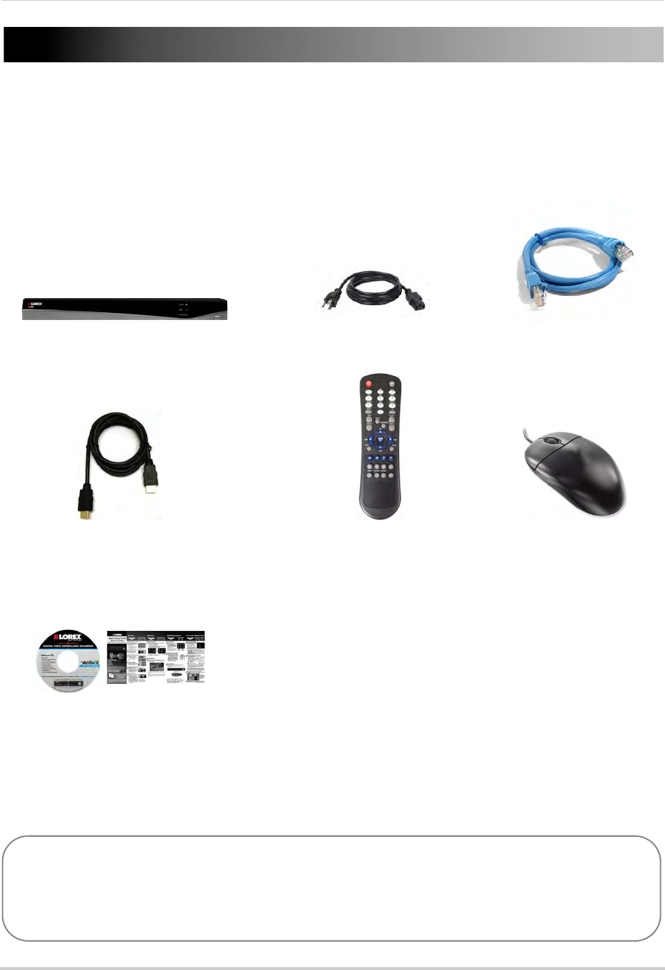
The system comes with the following components:
POWER CABLE
QUICKSTART GUIDES
DOCUMENTATION CD
USB MOUSE
ETHERNET CABLE
REMOTE CONTROL
(may not be exactly as
shown)
NVR (NETWORK VIDEO RECORDER)
HDMI CABLE
HARD DRIVE SIZE, NUMBER OF CHANNELS, AND CAMERA CONFIGURATION MAY VARY
BY MODEL. PLEASE REFER TO YOUR PACKAGE FOR SPECIFIC DETAILS.
CHECK YOUR PACKAGE TO CONFIRM THAT YOU HAVE RECEIVED THE COMPLETE SYSTEM,
INCLUDING ALL COMPONENTS SHOWN ABOVE.
2
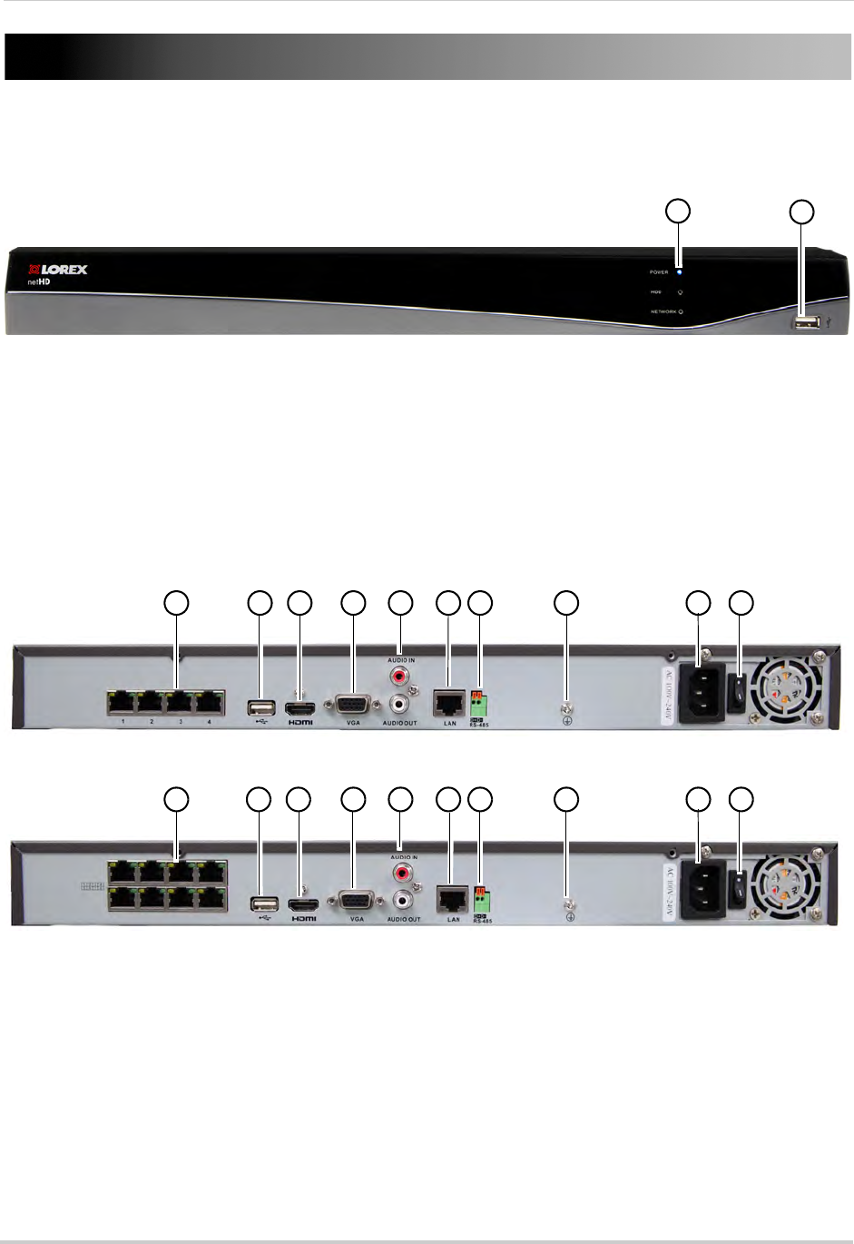
NVR Overview
Front Panel
12
1LED Indicators:
• POWER: Power LED.
• HDD: Recording status LED
• NETWORK: Network status LED.
2USB Port: Connect a USB mouse (included) or USB flash drive (not included) for data backup
or firmware updates.
4-Channel
1 2 3 4 5 6 7 8 9 10
8-Channel
1 2 3 4 5 6 7 8 9 10
1Camera In: Connect IP cameras. Integrated PoE (Power Over Ethernet) ports provide power
to cameras and video connection to NVR.
2USB Port: Connect a USB mouse (included) or USB flash drive (not included) for data backup
or firmware updates.
3HDMI Port: Connect an HDTV or monitor to view the system interface.
4VGA Port: Connect a VGA monitor to view the system interface.
5Audio IN/Audio OUT: Connect a microphone (not included) and 1 audio output device (e.g.
speakers; not included).
3
6LAN: Connect a CAT5 RJ45 Ethernet cable for local and remote connectivity.
7RS485: Not supported.
8Ground
9Power Port: Connect the included power cable.
10 Power Switch: Turns the NVR on / off.
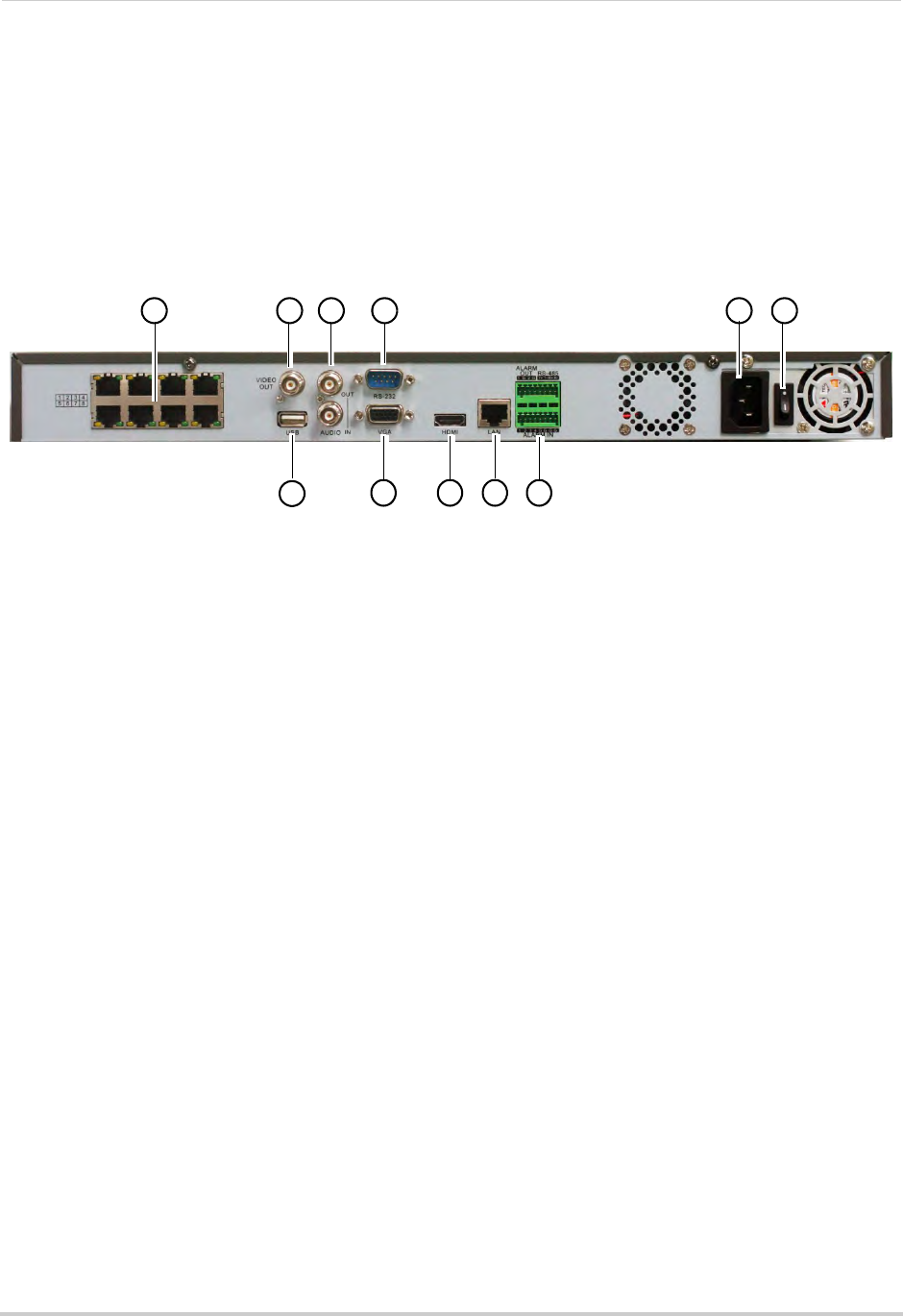
16-Channel
1 2
7
3 4 5 6
8 9 10 11
1Camera In: Connect IP cameras 1~8. Integrated PoE (Power Over Ethernet) ports provide
power to cameras and video connection to NVR.
NOTE: To connect cameras 9~16, see “Connecting Cameras over the Local Network” on page 9.
2Video Out: Outputs the live display to a secondary monitor using a BNC cable (not included).
NOTE: You cannot see the mouse or system menus via BNC. Use a BNC to RCA adapter (not
included) to connect the NVR to RCA inputs (i.e. for a TV connection).
3Audio IN/Audio OUT: Connect a microphone (not included) and 1 audio output device (e.g.
speakers; not included).
4RS-232: Service only; not supported.
5Power Port: Connect the included power cable.
6Power Switch: Turns the NVR on / off.
7USB Port: Connect a USB mouse (included) or USB flash drive (not included) for data backup
or firmware updates.
8VGA Port: Connect a VGA monitor to view the system interface.
9HDMI Port: Connect an HDTV or monitor to view the system interface.
10 LAN: Connect a CAT5 RJ45 Ethernet cable for local and remote connectivity.
11 RS485/Alarm: Not supported.
4
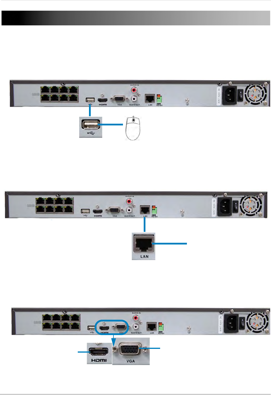
Basic Setup
Step 1: Connect the Mouse
• Connect a USB mouse (included) to the USB port on the rear panel.
8-channel model shown
USB port
Step 2: Connect the Ethernet Cable
• Connect an Ethernet cable (included) to the LAN port on the rear panel. Connect the other
end of the Ethernet cable to a router on your network.
Connect Ethernet cable
8-channel model shown
LAN port
Step 3: Connect the Monitor
• Connect a HDMI cable (included) from the HDMI port to the TV or monitor (recommended) OR;
• Connect a VGA cable (not included) from the VGA port to the monitor.
HDMI VGA
8-channel model shown
5
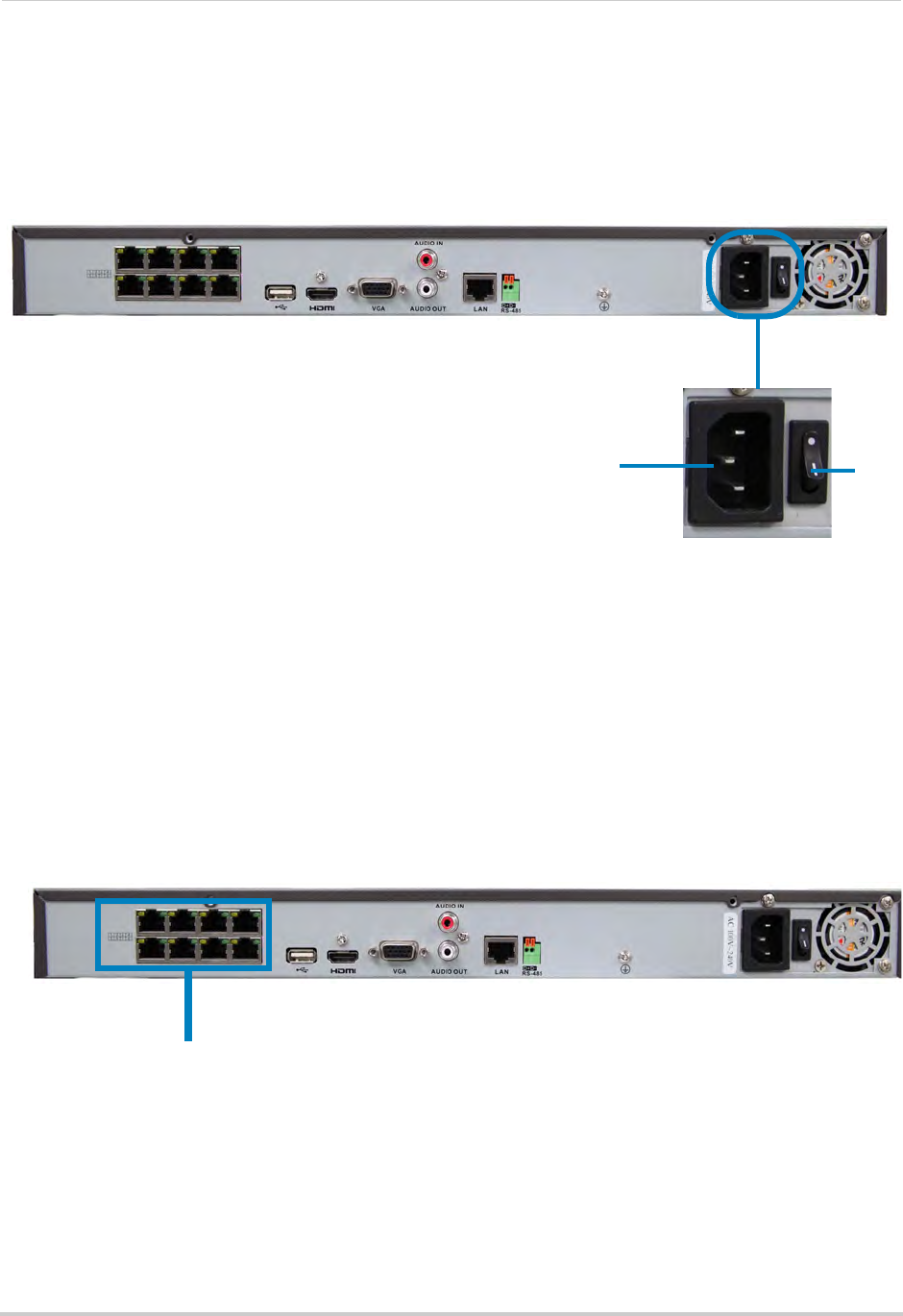
Step 4: Connect the Power Adapter and Power on the NVR
• Connect the included power cable to the Power port. Connect the end of the power cable to
a wall socket or a surge protector.
• Turn the power switch to I to turn on the NVR. At startup, the system performs a basic system
check and runs an initial loading sequence. After a few moments, the system loads a live
display view.
8-channel model shown
Power Port ON
Step 5: Connect the IP Cameras
NOTE: Only Lorex IP cameras are supported with the NVR.
Option 1: Direct Connection to NVR (Recommended)
The NVR features integrated Power over Ethernet (PoE) ports, which allow you to connect
cameras directly to the NVR.
Simply connect the IP cameras to the PoE ports on the rear panel of the NVR using Cat 5e
or higher Ethernet cable, and the cameras will appear on the NVR without any additional
configuration. The PoE ports will provide power to the cameras and facilitate the
transmission of video data to the NVR.
Connect IP Cameras directly to PoE ports
8-channel model shown
NOTE: The cameras may take up to 1 minute to power on and show an image on the monitor
after being connected to the NVR.
Option 2: Connect Cameras to Local Network
Since 16-channel models have only 8 PoE ports, you must connect channels 9~16 to the
local network by connecting them to the same router as the NVR. For details, see
“Connecting Cameras over the Local Network” on page 9.
6
Basic Setup
Step 6: Verify Camera Image
• Verify the camera video quality before mounting the cameras to a permanent location.
• Mount the cameras under a sheltered location. Always verify the outdoor rating of your camera
before installing it in a permanent location.
Step 7: Set the Time
• Set the system time and date for accurate video time stamps. Videos with inaccurate times
may not be valid as surveillance evidence.
• For details on setting the system time, see “Setting the Date and Time” on page 19.
Default System Password & Port Numbers
By default, the system user name is admin and the password is 000000.
Passwords are enabled by default and are required to access menus. It
is essential that you create your own password. For details, see
“Managing Passwords” on page 38.
• The system requires a user name and password to log in to the system remotely using a
computer or mobile device.
• After logging on remotely the first time, you will be asked to create a custom password for
the system.
Local NVR and remote connectivity (LAN & Internet) user name and password:
• Username: admin / Password: 000000
Default ports for DDNS remote access:
• Port 80 (HTTP port)
• Port 8000 (Client port)
• Port 1025 (Mobile port)
Lorex Stratus Connectivity
This system features the exclusive Lorex Stratus connectivity service. This is a cloud
connectivity service that allows you to connect to your system over the Internet via a secure
handshake with Lorex’s Stratus servers. This means you can easily connect to your system
without requiring any network configuration.
For details on setting up your system to connect to the Internet using the Stratus service:
• See “Connecting to Your NVR Over the Internet on PC or Mac” on page 83.
OR
• See “Mobile Apps: Accessing your NVR Using a Mobile Device” on page 132.
Connectivity using Lorex’s free DDNS service is also available, but requires the ports listed
above to be port forwarded on your router.
7
Basic Setup
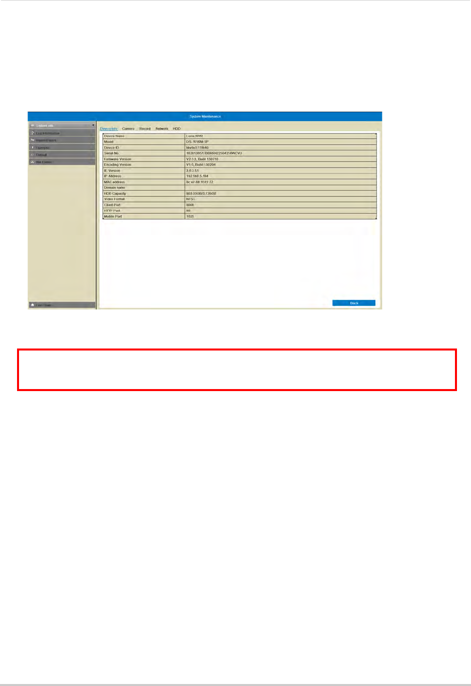
Quick Access to System Information
• To quickly open a window that displays vital system information, right-click and then click
Information.
OR, press the INFO button on the remote control.
Camera Installation Tips
ATTENTION: Cameras differ in terms of installation or mounting instructions. Please see
the documentation that came with your camera(s) for specific installation instructions.
Test the cameras before permanent installation. Plan where you will route the wiring for
the camera and where you will aim the camera.
Installation Tips
• Mount the camera where the lens is away from direct and intense sunlight.
• Plan your cable wiring so that it does not interfere with power lines or telephone lines.
• Ensure that the camera wiring is not exposed or easily cut.
• Mount the camera in an area that is visible, but out of reach.
• Avoid pointing the camera at a glass window to see outside, as this may result in a poor image
caused by glare from indoor / outdoor lighting conditions.
• Adjust the camera angle so that it covers an area with high traffic.
• In "high-risk" locations, have multiple cameras point in the same area. This provides camera
redundancy if a vandal attempts to damage the camera.
Installing Cameras
1Mount the camera(s) to the desired mounting surface according to the instructions that came
with the camera(s). Choose a firm mounting surface.
NOTE: If you wish to mount cameras to drywall, it is recommended to use drywall plugs (not
included).
8
Basic Setup
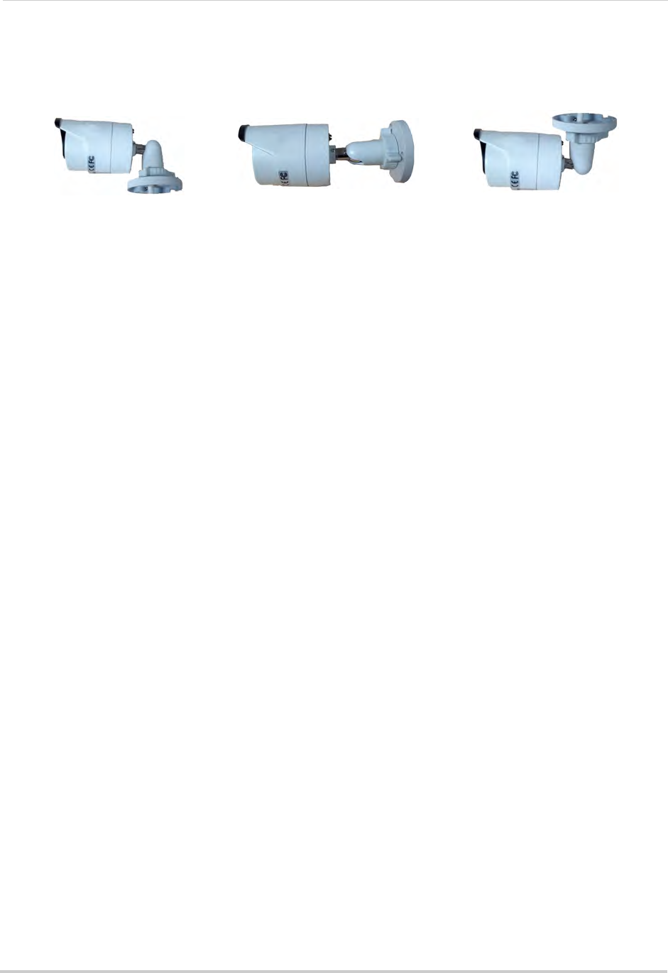
2Adjust the camera stand to ensure that the camera has a satisfactory view of the area you
would like to monitor. Stand configuration depends on the mounting surface you have chosen
(see below for suggested stand configurations).
Table Mount Wall Mount Ceiling Mount
Camera model not be exactly as shown.
3Connect a Cat5e or better Ethernet cable from the camera to the NVR. The NVR features
integrated PoE (Power over Ethernet) ports that provide both power and data transmission to
PoE-compatible cameras over the Ethernet cables.
NOTE: The cameras may take up to 1 minute to power on and show an image on the monitor
after being connected to the NVR.
9
Connecting Cameras over the Local Network
Connecting Cameras over the Local Network
You may also connect IP cameras to the same Local Area Network (LAN) as the NVR. This
is accomplished by connected the cameras to the same router as the NVR. This type of
installation is necessary to connect more than 8 cameras to 16-channel models, since they
only have 8 PoE ports available to connect cameras directly to the NVR.
For these installations, an external PoE switch (sold separately) or 12V DC power adapter
(not included) must be used to provide power to each IP camera. You also must add the
cameras on the NVR before they will show a picture on the monitor or be recorded by the
NVR. Follow the steps below to connect the cameras to the NVR over the LAN.
To connect cameras to your local network:
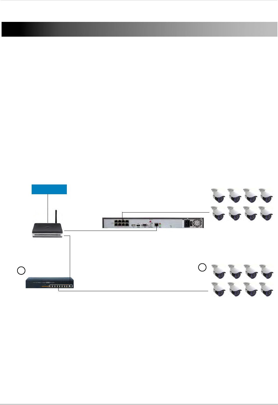
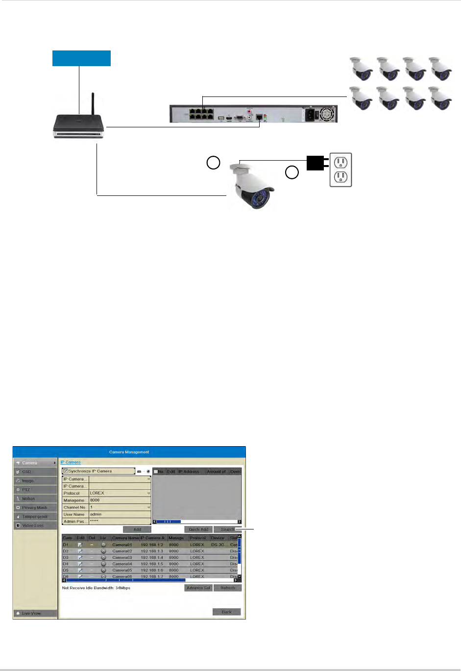
1A. Connect an Ethernet cable from the LAN port* on an external PoE switch (Lorex model:
ACCLPS281B, sold separately) to your router using a CAT5e or higher Ethernet cable.
Connect the power cable to the PoE swtich and to a power outlet or surge protector.
B. Connect the IP cameras to ports 1~8* on the PoE switch using the Ethernet extension
cables. The PoE switch will provide power and video transmission the same way your NVR
does.
Router
IP Cameras 9~16
16-channel NVR (8 PoE Ports)
PoE Switch
INTERNET
IP Cameras 1~8
Connecting Cameras to Local
Network using external PoE Switch
AB
OR
A. Connect the cameras to a 12V DC power adapter (visit www.lorextechnology.com for
compatible power adapters for your cameras.
B. Connect the camera to your router using a CAT5e or higher Ethernet cable.
* The terminology may vary depending on the model of your PoE switch. See the instructions for your specific PoE switch
for details.
Router
IP Camera
16-channel NVR (8 PoE Ports)
INTERNET
IP Cameras
Connecting Cameras to Local
Network using 12V DC power adapter
12V DC Power adapter
(not included)
AB
10
Connecting Cameras over the Local Network
2The steps to open the IP cameras on the NVR differs depending on the number of channels
your NVR has. Follow the appropriate steps below.
Connecting Cameras Over the Local Network on 16-Channel Models:
NOTE: These steps only apply to 16-channel models. To add cameras over the local network
to a 4 or 8-channel NVR, see “Connecting Cameras Over the Local Network on 4/
8-Channel Models (Advanced):” on page 11.
1Right-click and click Menu. Enter the NVR’s user name (default: admin) and password
(default: 000000) and click OK.
2Click Camera.
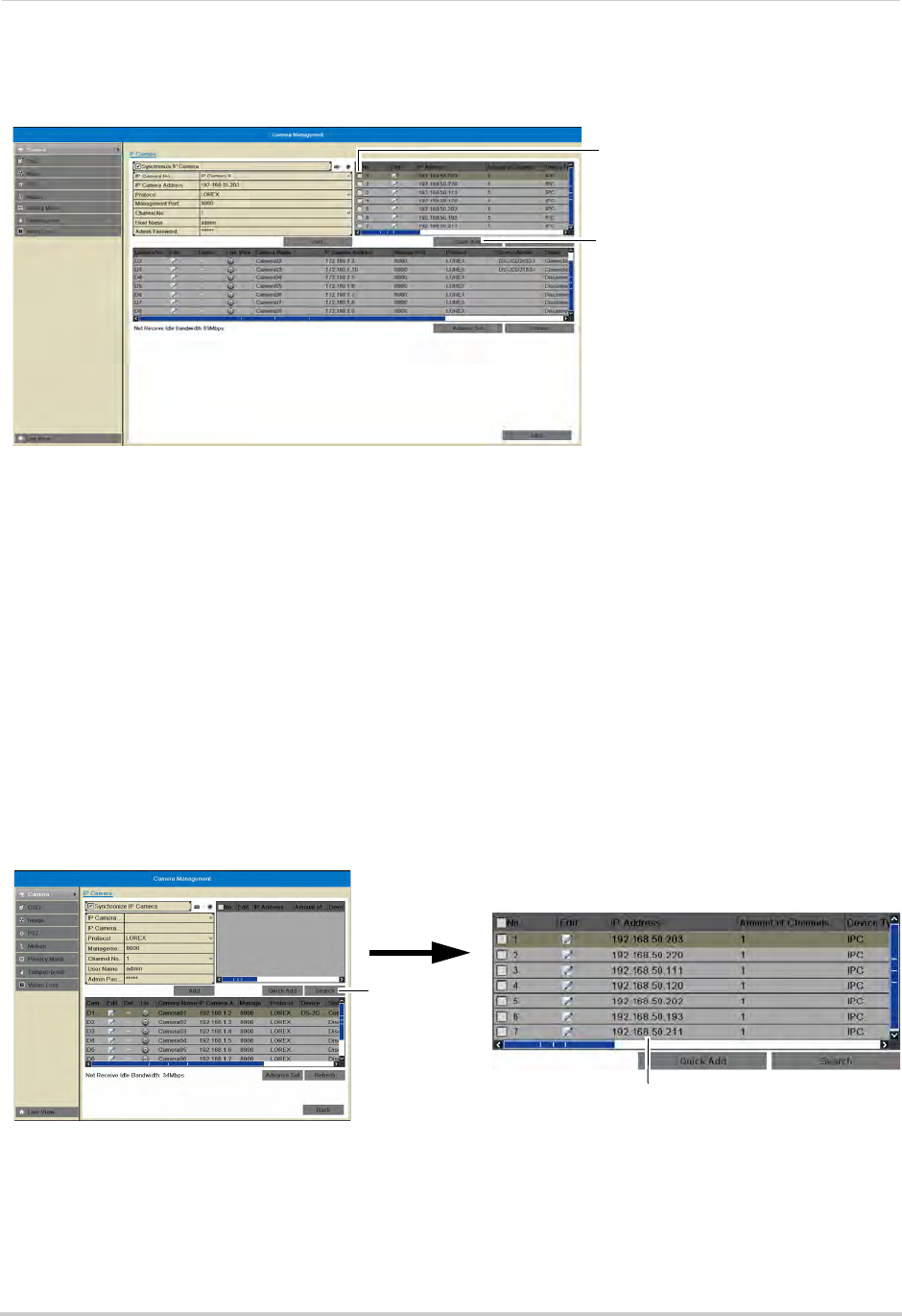
3Click Search. The NVR scans for IP cameras on your local network.
Click Search
11
Connecting Cameras over the Local Network
4Check the cameras you would like to add to the NVR and click Quick Add. Right-click
repeatedly to return to live view.
Check the cameras
Click Quick Add
NOTE: IP cameras connected to the local network may only be assigned to channels 9~16.
Connecting Cameras Over the Local Network on 4/8-Channel Models
(Advanced):
Because all the channels are assigned to the PoE ports on 4/8-channel NVRs, you cannot
add cameras to the NVR using the steps for 16-channel models. You must override the
settings for the PoE channels to connect cameras over the local network.
To connect cameras over the local network on 4/8-channel models:
1Right-click and click Menu. Enter the NVR’s user name (default: admin) and password
(default: 000000) and click OK.
2Click Camera.
3Click Search. The NVR scans for IP cameras on your local network.
4Write down the IP addresses of the camera(s) you would like to add.
Click Search
Write down the camera
IP address
12
Connecting Cameras over the Local Network
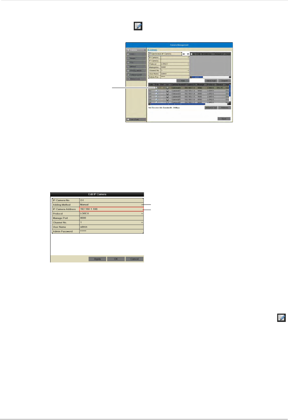
5In the bottom portion of the screen, click on the channel you would like to assign to the
camera.
Click the channel you
want to re-assign
NOTE: If a camera is connected to the corresponding PoE port, it will be disconnected. You can
tell if a camera is connected to a given port because it will say Connected under the
status column.
6Under Adding Method, select Manual.
7Under IP Camera Address, replace the existing address with the IP address of the camera
you recorded in step 4.
Select Manual
Enter the camera’s IP
address
8Click OK.
9Right-click repeatedly to return to live view. It make take a few seconds for the camera to
appear.
NOTE: Performing the steps above disables the PoE port, and the NVR will not recognize if a
camera is connected to the disabled port. If you wish to use the PoE port again, click
on the channel and change Adding Method back to Plug and Play. Then return to live
view and connect the new camera to the PoE port. It may take up to a minute for the
camera to appear on the monitor.
13
Mouse Control
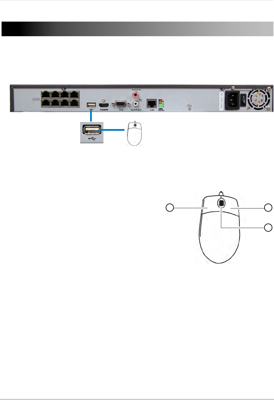
Mouse Control
The NVR is designed for mouse navigation. To use a USB mouse (included), connect the
mouse to a USB port on the NVR.
8-channel model shown
USB port
Use the mouse buttons to perform the following:
1Left-Button:
• Click to select a menu option.
• During live viewing, click on a camera to bring up
the Camera Toolbar. See “Using the Camera
Toolbar” on page 16.
1 2
3
• During live viewing in split-screen view,
double-click on a channel to view the selected
channel in full-screen; double-click the channel
again to return to split-screen view.
2Right-Button:
• Click to open the Quick Menu. See “Using the Quick
Menu” on page 17.
• In menus, use the right-button to go back / exit
menus.
3Scroll-Wheel:
• During live view, scroll up / down to change channel.
• Scroll up / down to adjust menu options.
14
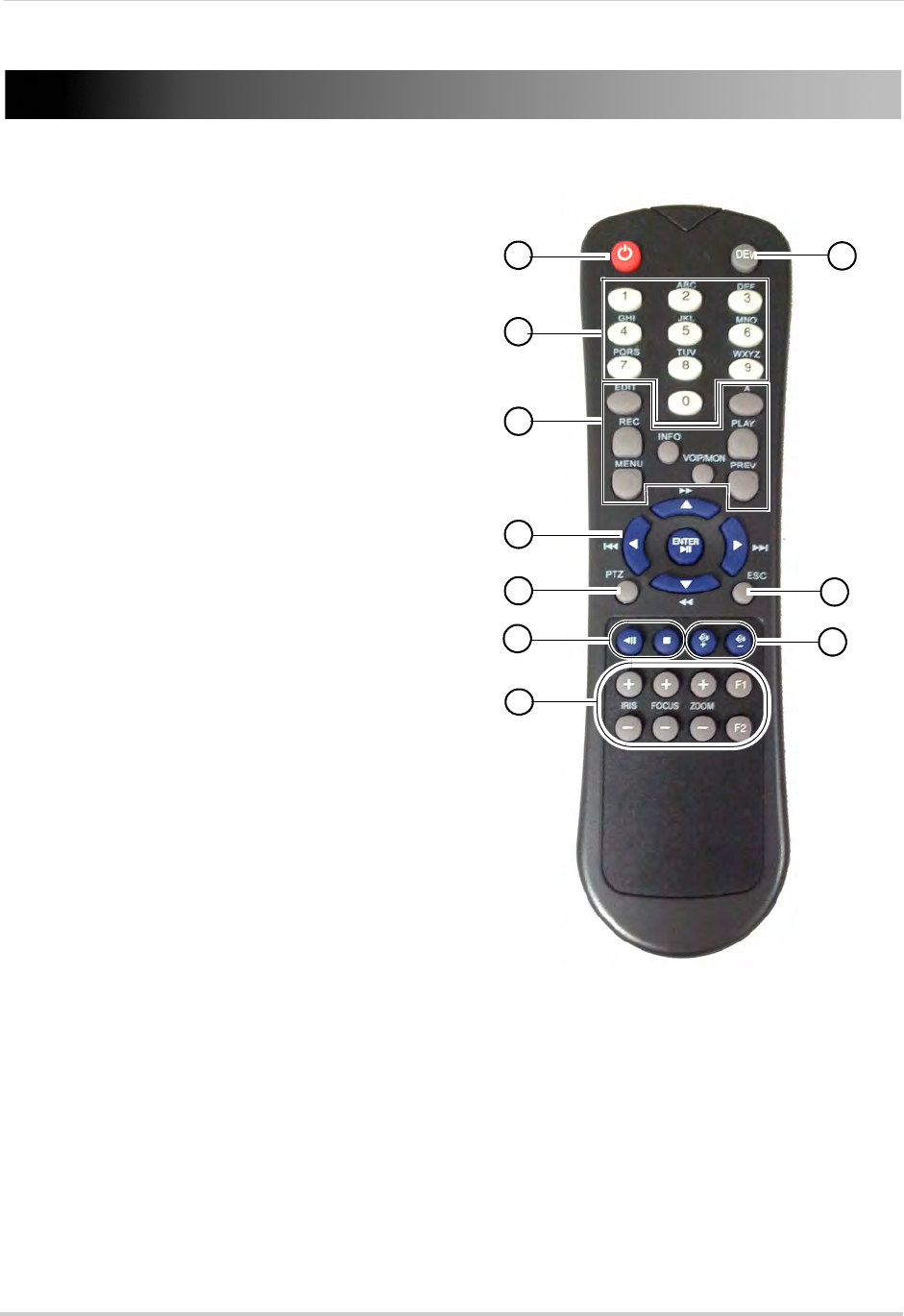
Remote Control
Remote Control
You can also control the NVR using the
included remote control.
3
5
6
8
10
1
4
2
7
9
1Power: Press and hold to power off the NVR.
Wait for the message that the NVR has shut
down, then use the power switch to power off
the NVR.
2DEV: Use to pair the remote control with a
specific NVR. For details, see “Pairing the
Remote Control” on page 68.
3Number Keys:
• In live view, press to select a channel.
• In menus, press to enter characters.
4Function Buttons:
• EDIT: Press while a menu option is selected
to enable numeric or text input. For details,
see “Using the Remote Control to Enter Text
or Numbers” on page 15.
• REC: Press to open the manual recording
menu.
• MENU: Press to open the Main Menu.
• INFO: Press to view system information.
• PLAY: Press to open Playback mode.
• A: When Edit Mode is selected, press
repeatedly to select keyboard types.
• PREV: In live view, press to select different
split-screen views.
• VOIP/MON: Not supported.
5Navigation Cursors / Playback Controls:
• Press to move the cursor in menus.
• ENTER / : Press to enter menu selections. In Playback Mode, press to pause / play video.
In live view, press to start / stop Sequence mode.
• : In Playback Mode, press to fast forward / increase fast forward speed.
• : In Playback Mode, press for slow playback. Press repeatedly to reduce playback speed.
• : In Playback Mode, press to skip ahead 30 seconds.
• : In Playback Mode, press to skip back 30 seconds.
6PTZ: Not supported.
7ESC: Press to go back / exit menus.
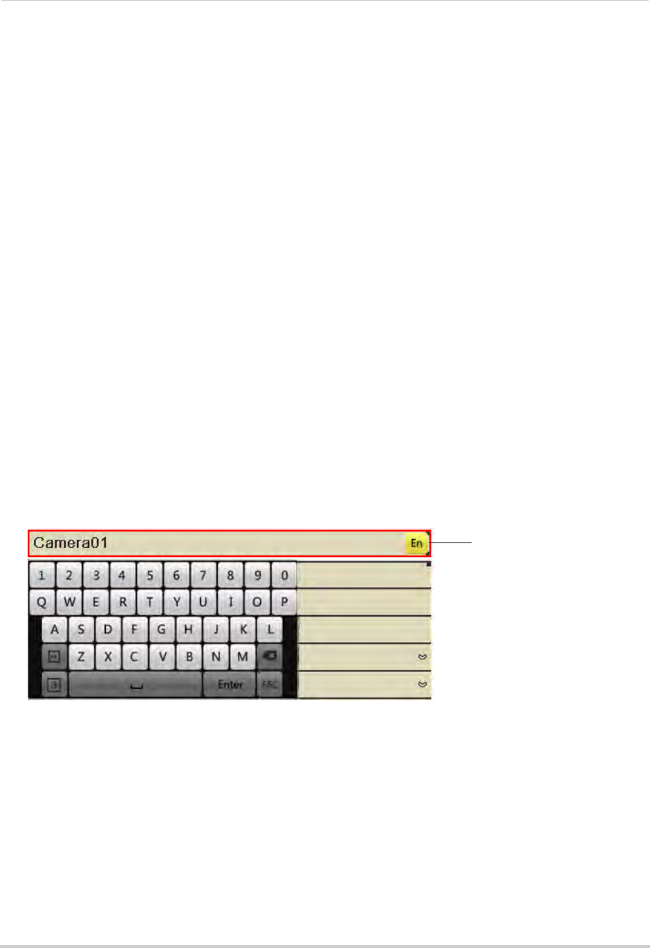
15
Remote Control
8|: Not supported.
•
.
: Not supported.
9Volume + / -: Press to adjust volume.
NOTE: A microphone (not included) is required to use audio function.
10 Miscellaneous:
• F2: Select next tab in menu.
• F1: Not supported.
• ZOOM + / -: Not supported.
• IRIS + / -: Not supported.
• FOCUS + / -: Not supported.
Using the Remote Control to Enter Text or Numbers
The remote control can be used in menus to enter text or numeric entries.
To use the remote control for text or numeric entry:
1Use the arrow buttons to select a menu item that requires a text or numeric input.
2Press EDIT.
3Press the number keys to enter text or numbers. Press repeatedly to enter the letters printed
above the button.
An icon shows the currently selected keyboard type.
To change the keyboard, press A. Available keyboards are:
Current keyboard type
• En: Lowercase English letters.
• A: Uppercase English letters.
• 123: Numbers.
• .,: Special characters.
4Press Enter to confirm your entry. You may now use the arrow buttons to move the menu
cursor.
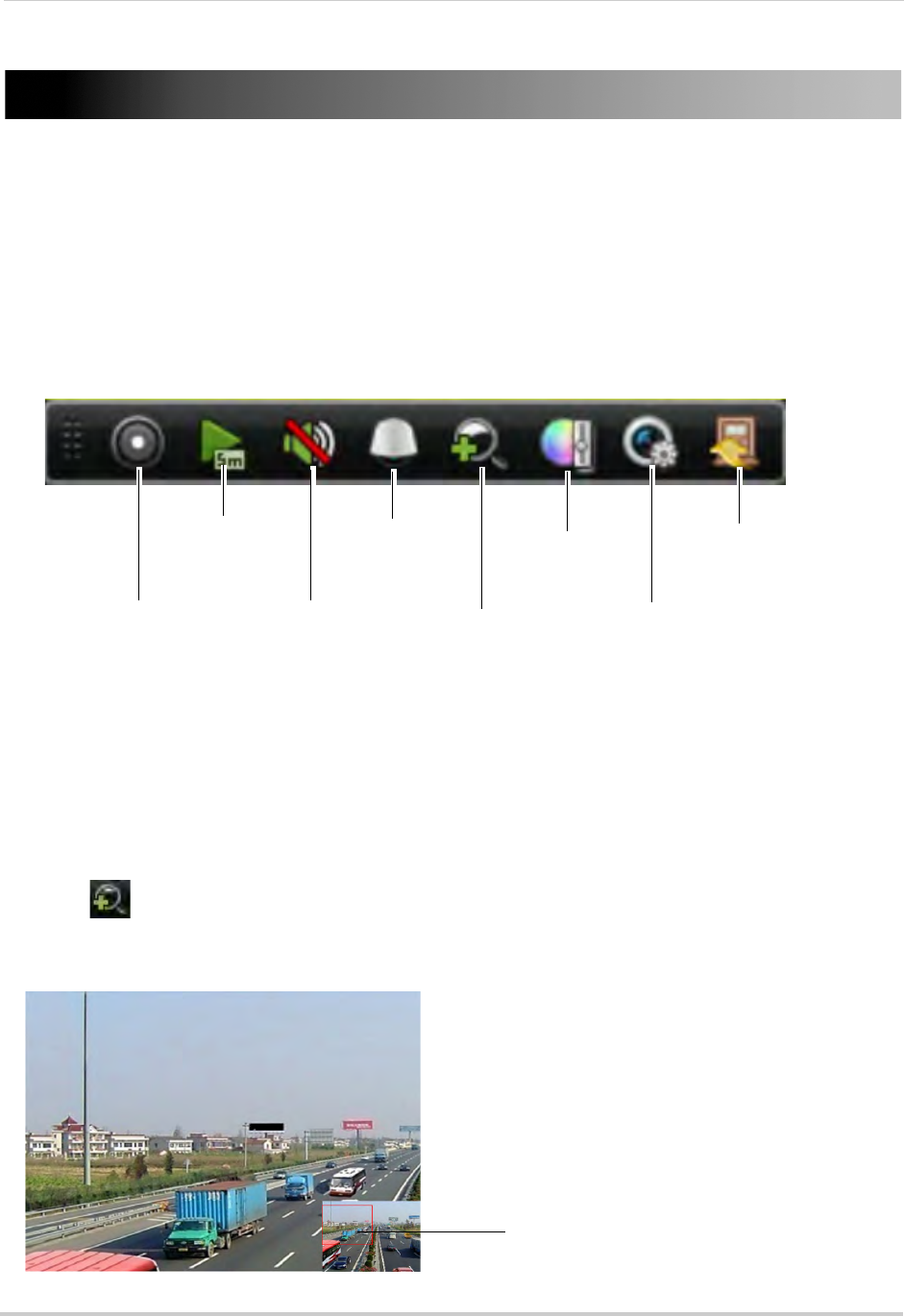
16
Using the On-Screen Display
Using the On-Screen Display
Use the system’s graphical on-screen display to navigate menus and configure options and
settings.
Using the Camera Toolbar
The Camera Toolbar allows you to quickly access key controls for each camera.
To use the Camera Toolbar:
1In live view, click inside the camera to open the Camera Toolbar.
Start/Stop
Recording
Open Quick
Playback
Mute
Volume /
Unmute
Not supported
Digital Zoom
Image Settings
Live View
Strategy
Close
Camera
Toolbar
Using Digital Zoom
Zoom Mode allows you to zoom in on an image while viewing your cameras live. This can
be useful if you want to get a closer look at a situation.
To use Digital Zoom:
1If you are in split-screen click on the camera you would like to zoom in on to open the Camera
Toolbar.
2Click to open Digital Zoom. Digital Zoom opens to the default zoom level. The box in the
bottom right-corner of the screen shows the entire image as seen by the camera.
3
Click and drag to
change the zoom area
To change the zoom area, click and drag inside the box in the lower right corner.
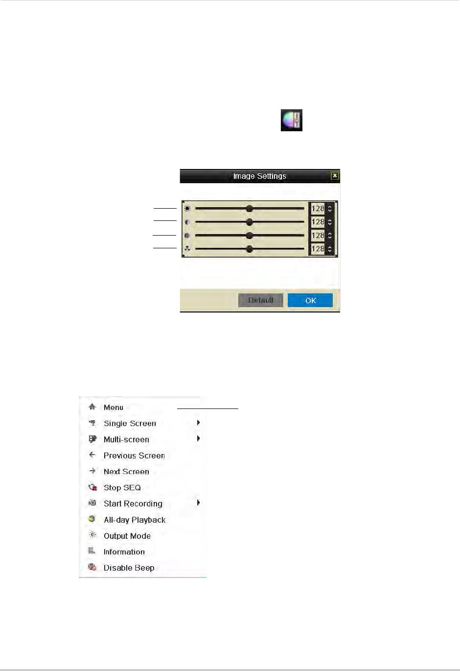
17
Using the On-Screen Display
4Right-click to exit Digital Zoom.
Adjusting Camera Image Settings
Use the Image Settings screen to adjust the color settings for your cameras.
To adjust the camera Image Settings:
1Click inside the camera you would like to edit and click .
2Use the sliders to adjust the Brightness, Contrast, Saturation, and Hue. Note that it may take
a couple seconds for changes to occur.
Brightness
Contrast
Saturation
Hue
3Click OK to save changes.
Using the Quick Menu
The Quick Menu allows you to select display options on the monitor, use quick controls, and
access the Main Menu for the NVR.
Right-click to open
Quick Menu
To access the Quick Menu:
1Right-click during live view to open the Quick Menu. The Quick Menu has the following
options:
• Menu: Open the Main Menu. For details, see “Using the Main Menu” on page 42.
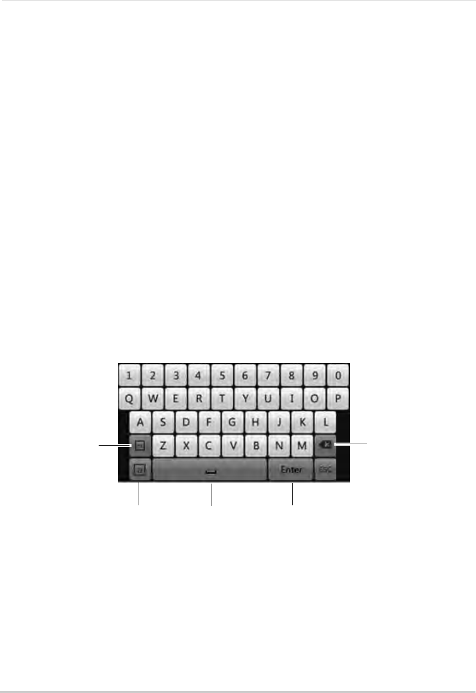
18
Using the On-Screen Display
• Single Screen: Open a camera in full screen.
• Multi-Screen: Select a split-screen layout.
• Previous Screen: Select the previous channel or group of channels (e.g. if 2x2 Multi-Screen
is selected, click Previous Screen to see the next 4 channels).
• Next Screen: Select the next channel or group of channels.
• Start/Stop SEQ: Start/stop Sequence Mode (NVR automatically changes channels every few
seconds.
• Start Recording: Select Continuous & Motion Record to start 24/7 continuous and motion
recording on all channels. Select Motion Detection Record to start 24/7 motion detection
recording on all channels.
• All-day Playback: Open Playback Mode for the currently selected channel. For details, see
“Using All-day Playback” on page 23.
• Output Mode: Click to adjust the color output mode for your monitor. Select the color output
mode that looks best on your monitor: Standard, Bright, Gentle, or Vivid, and then click OK.
• Information: Click to access system information.
• Disable Beep: Disables the system beep for alarms until the next alarm occurs.
Using the Virtual Keyboard
You can input numeric or text values using the on-screen virtual keyboard. You will need to
use the Virtual Keyboard when entering your User Name and Password.
To use the Virtual Keyboard:
1Click on a menu option the requires text input.
• The Virtual Keyboard opens.
Toggle uppercase /
lowercase Space Confirm
Input
Enter special
characters Backspace
2Enter your text entry and then press Enter.
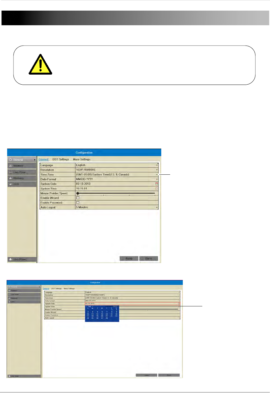
19
Setting the Date and Time
It is highly recommended to set the date and time when first
setting up your system.
Inaccurate time stamps may render your footage unusable for
court evidence.
To set the date and time:
1Right-click to open the Quick Menu and then click Menu.
2Enter the NVR’s user name (default: admin) and password (default: 000000) and click OK.
3Click Configuration.
4Under Time Zone, select your Time Zone.
Select your Time Zone
5Click System Date and then use the on-screen calendar to select the current date.
Click System Date and use
the calendar to select the
current date
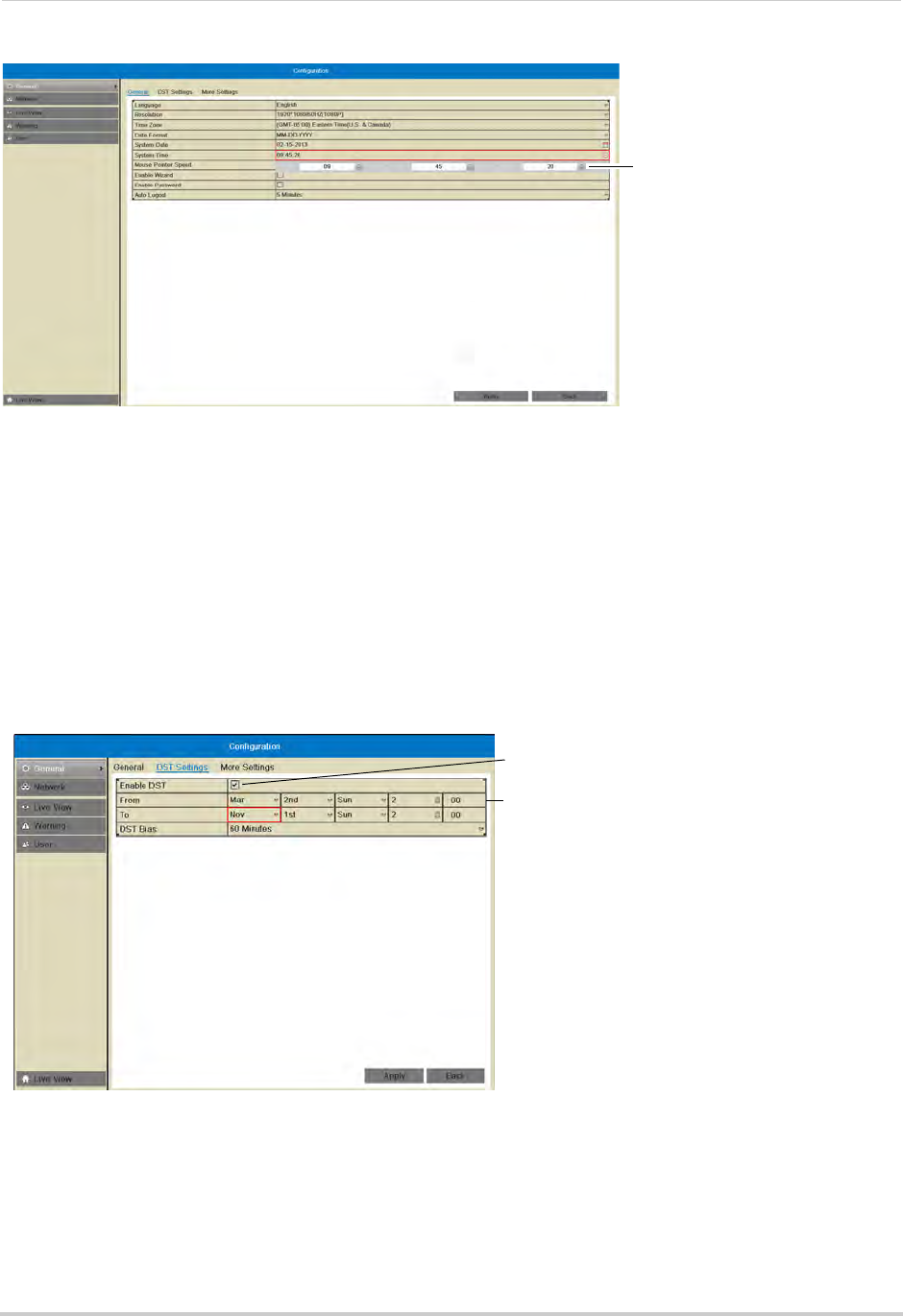
20
6Click System Time and then click the up and down buttons to set the time.
Click System Time and click up
and down to set the time
7Click Apply to save changes. Right-click repeatedly to return to live view.
Configuring Daylight Savings Time (DST)
If your region observes Daylight Savings Time (DST), follow the instructions below to
configure your NVR to automatically update the time when the clock updates.
To enable automatic DST adjustments:
1Right-click to open the Quick Menu and then click Menu.
2Enter the NVR’s user name (default: admin) and password (default: 000000) and click OK.
3Click Configuration and then click the DST Settings tab.
Check Enable DST to use
default DST settings
Check Auto DST Adjustment
and select custom DST start
and end times
4Check Enable DST and configure the following:
• From: Select the start time for Daylight Savings.
• To: Select the end time for Daylight Savings
• DST Bias: Select the amount of time the clock changes when DST starts and ends.
5Click Apply to save changes.
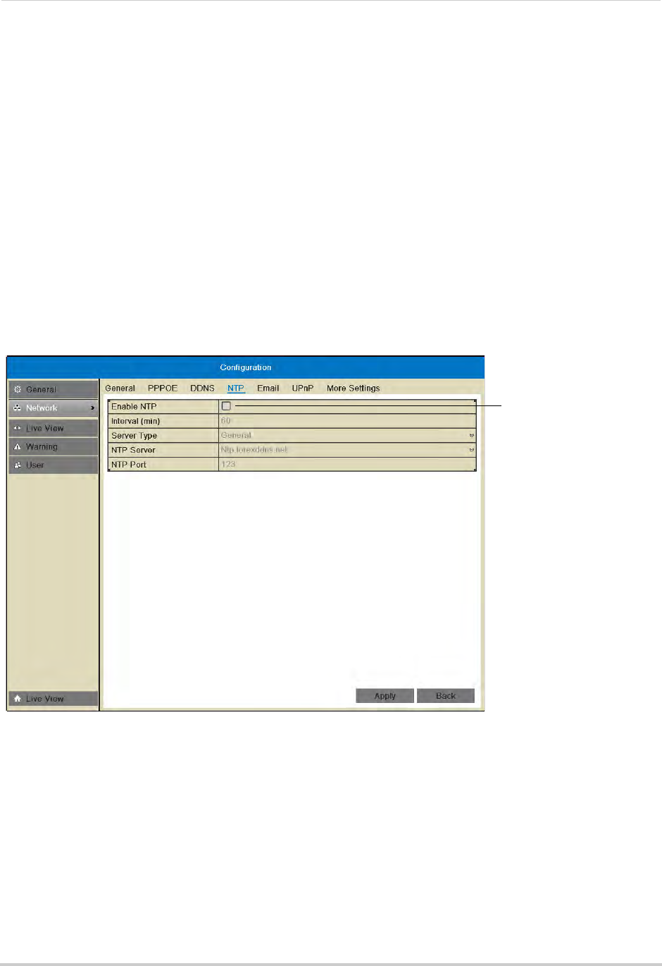
21
Setting the Date and Time
Using a NTP Server to set your System Time
A NTP (Network Time Protocol) server syncs your system time with an online time server.
Lorex provides a free NTP service that allows your NVR to automatically update the time
for Daylight Savings Time.
NOTE: A constant Internet connection is required to use the NTP feature.
To enable NTP:
1Before setting up NTP, select your time zone under Menu>General>Time Zone and click
Apply.
2Right-click to open the Quick Menu and click Menu.
3Enter the NVR’s user name (default: admin) and password (default: 000000) and click OK.
4Click Configuration>Network>NTP.
5Check Enable NTP.
Check to
enable NTP
6(Optional—advanced) Configure the following:
• Interval (min): Enter how often the NVR will access the NTP server to update the time.
• Server Type: Select General to use the default Lorex NTP server or select Customize to enter
a custom server.
• NTP Server: Select the NTP server or enter the NTP server address.
• NTP Port: Enter the port number of the NTP server.
7Click Apply. The NVR connects to the server and updates the time.

22
Recording
Recording
By default, the system is set to immediately record video from connected cameras in
Continuous & Motion Recording Mode on a 24/7 schedule.
Recording Modes
The system supports the following recording modes:
• Continuous & Motion Recording Mode: The system will record continuously during all times
included in the schedule. The system will mark motion events when any of the cameras detect
motion.
• Motion Detection Recording Mode: The system will only record when motion is detected by
the cameras.
• Manual Recording Mode: The system will record when manual recording is enabled. To
enable/disable manual recording, click on the camera and then click .
Recording Icons
The following icons appear in red to indicate recording:
•
C
.
Recording—Continuous: Continuous recording is in progress.
•
M
.
Recording—Motion: Motion recording is in progress. Icon appears in green when
motion is detected, but the NVR is not recording.
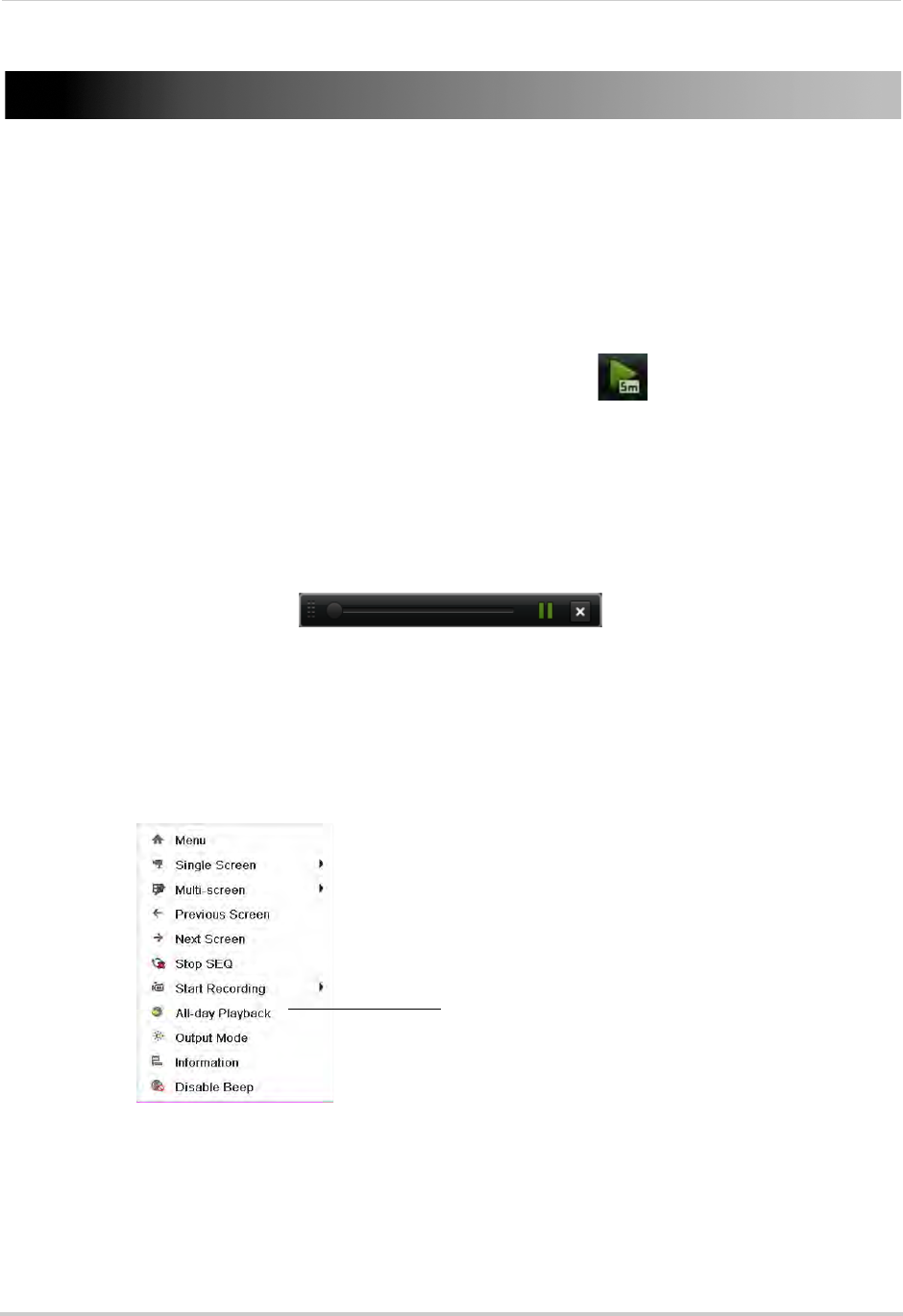
23
Playback
Playback
You can use the following options to view recorded video on the system.
Using Quick Playback
Quick Playback plays back footage from the last five minutes for the selected camera.
To use Quick Playback:
1Click inside the camera you would like to playback and click .
2Quick Playback mode opens. If you select Quick Playback from split-screen view, the other
channels on screen will remain in live view, so you can keep monitoring your other cameras
while accessing recorded footage.
NOTE: A message appears on screen if no footage is available for the selected camera in the
last five minutes.
3Use the Quick Playback controls. When finished, click X to exit Quick Playback.
Quick Playback controls
Using All-day Playback
All-Day Playback opens footage from the last 24-hours for the selected camera.
To use All-Day Playback:
1Right-click inside the camera you would like to playback and then click All-day Playback.
Right-click inside the camera
you would like to playback and
click All-day Playback
2Enter the NVR’s user name (default: admin) and password (default: 000000) and click OK.
Playback mode opens showing video for the previous 24 hours.
3Use the on-screen playback controls. For details, see “Using the On-Screen Playback
Controls” on page 29.
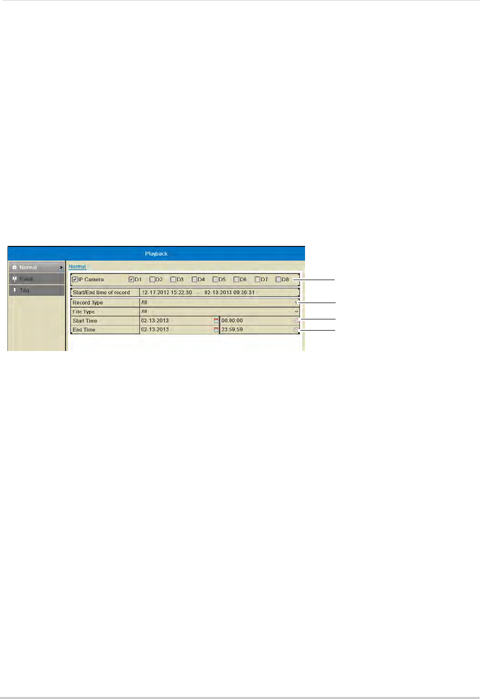
24
Playback
Using the Playback Menu to Search for Recordings
You can use the Playback menu to search for recordings on the system. You can search by
time, by event type (e.g. motion), or by tags.
Normal Search
The Normal Search menu is used to search for video based on a specified start and end
time.
To search for video using a start and end time:
1Right-click and then click Menu.
2Enter the NVR’s user name (default: admin) and password (default: 000000) and click OK.
3Click Playback.
4Under IP Camera, check the cameras you would like to search for video. Check IP Camera to
select/deselect all cameras.
Select cameras to
playback
Select recording
type
Select Start Time
Select End Time
5Under Record Type, select the types of recording you would like to search for: Continuous &
Motion, Motion, Manual, or All.
6Under Start Time, select the start time for your search. Click inside the field on the left and
use the calendar to select the start date. Click inside the field on the right and use the
buttons to adjust the start time for playback. Click outside the field to confirm the time.
NOTE: If you right-click, it will exit the Normal Search menu.
7Under End Time, select the end time for your search in the same way that you selected the
Start Time.
8Select one of the following:
• Click Playback to start playback at the earliest available footage in your selected time range.
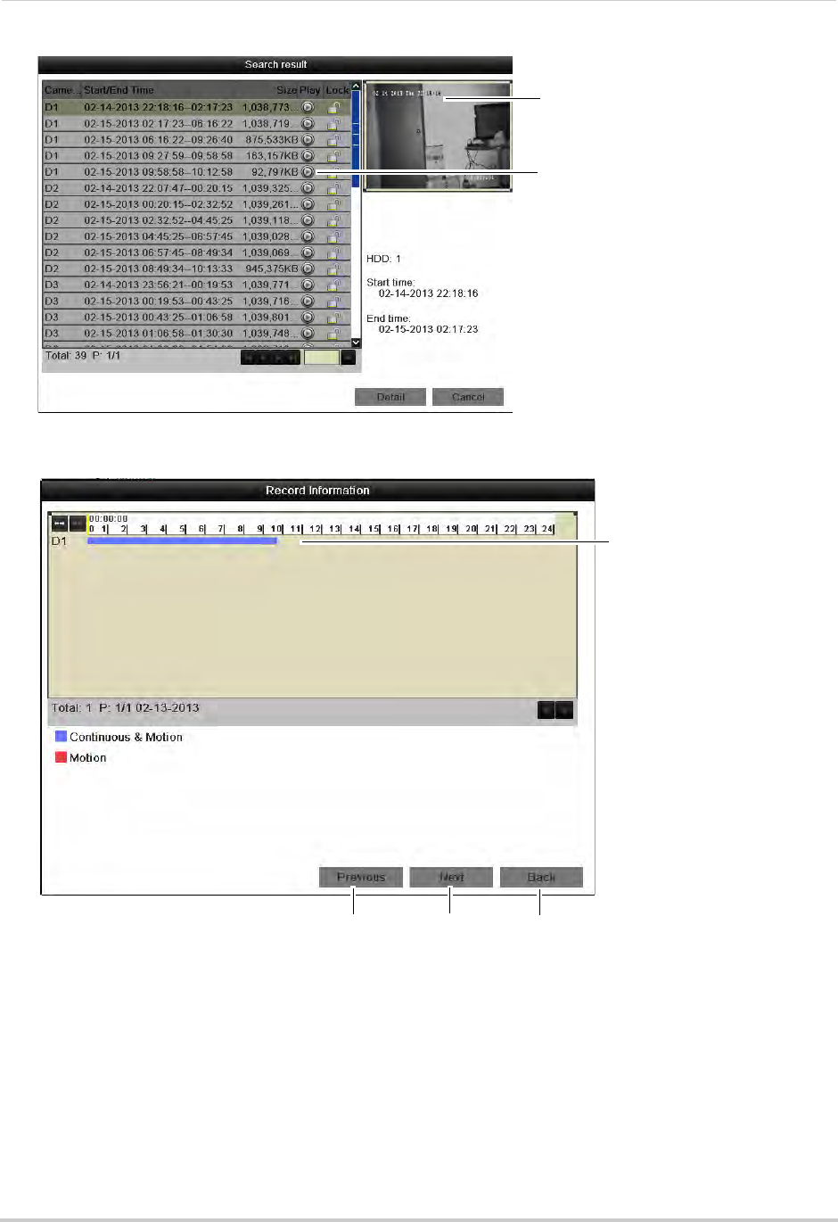
25
Playback
• Click Search to view a list of available footage in your time range.
Preview of video footage
Click to play a video file
• Click Detail to view a summary of available footage on the system, starting with the earliest
day in your selected time range.
Video information
Previous day Next day Exit
Locking Video Files
You can lock video files on the system to protect them from being overwritten when the
hard drive is full.
To lock video files:
1Right-click and click Menu.
2Enter the NVR’s user name (default: admin) and password (default: 000000) and click OK.
3Click Playback.
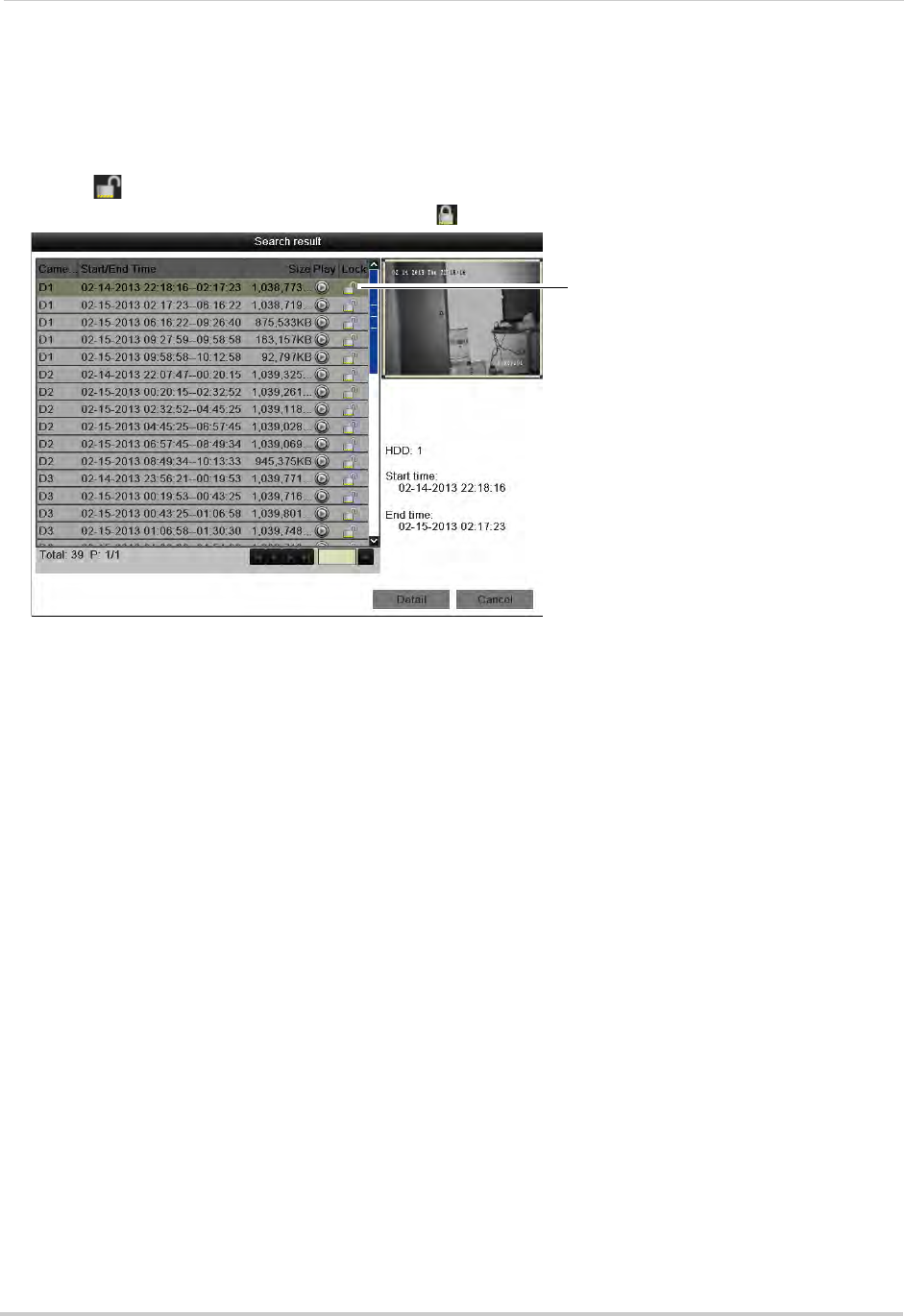
26
Playback
4Under IP Camera, check the cameras you would like to search for footage. Check/un-check
IP Camera to select/deselect all cameras.
5Configure the Record Type, File Type, Start Time, and End Time as needed and click Search.
A list of files appears, based on your search.
6Click to lock/un-lock files. Locked files will not be overwritten when the internal hard
drive is full. Locked files are shown with a
Click to lock/un-lock files
.
7Click Cancel to exit. Changes are saved when exiting.
Event Search
The Event Search menu is used to search for video with motion recordings.
To search for video with motion recording enabled:
1Right-click and then click Menu.
2Enter the NVR’s user name (default: admin) and password (default: 000000) and click OK.
3Click Playback and then Event.
4Under Start Time, select the start time for your search. Click inside the field on the left and
use the calendar to select the start date. Click inside the field on the right and use the
buttons to adjust the start time for playback. Click outside the field to confirm the time.
5Under End Time, select the end time for your search in the same way that you selected the
Start Time.
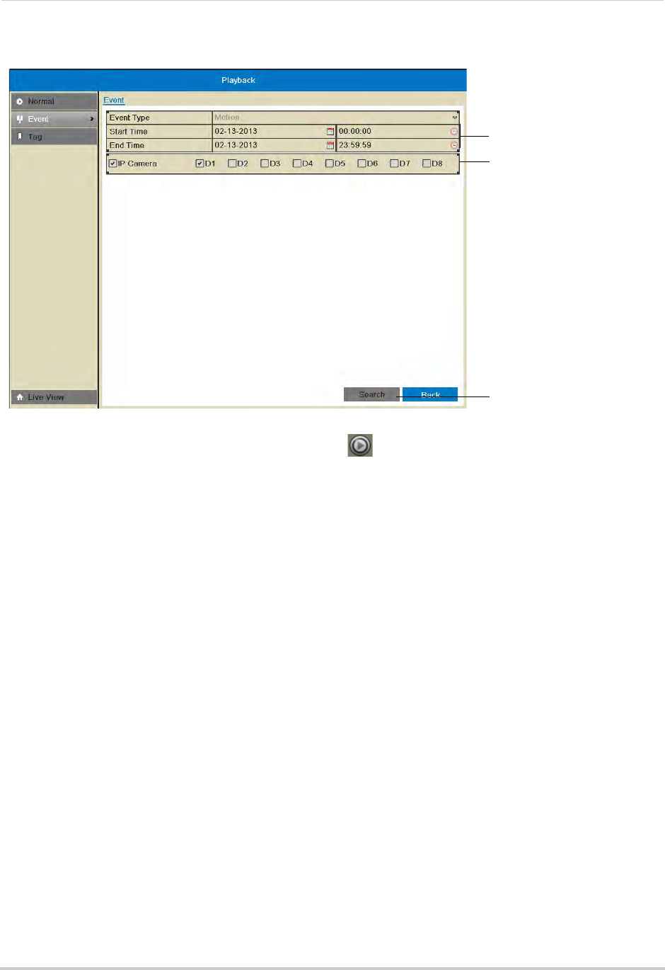
27
Playback
6Under IP Camera, check the cameras you would like to search for footage. Check/un-check
IP Camera to select/deselect all cameras.
Select Start and End Time
Select cameras to search
Click Search
7Click Search. Video with motion is listed. Click to playback a video file. Click Cancel to
exit the search results.
Tag Search
The Tag Search menu is used to search for video with user created tags. For details on how
to create tags, see “Tagging Video Footage” on page 31.
To search for video using tags:
1Right-click and then click Menu.
2Enter the NVR’s user name (default: admin) and password (default: 000000) and click OK.
3Click Playback then Tag.
4Under IP Camera, check the cameras you would like to search for footage. Check/un-check
IP Camera to select/deselect all cameras.
5Under Tag Type, select all to search for all tags in the system. Select Tag Keyword to search
for specific tags then enter the search query below (similar to a web search).
6Under Start Time, select the start time for your search. Click inside the field on the left and
use the calendar to select the start date. Click inside the field on the right and use the buttons
to adjust the start time for playback. Click outside the field to confirm the time.
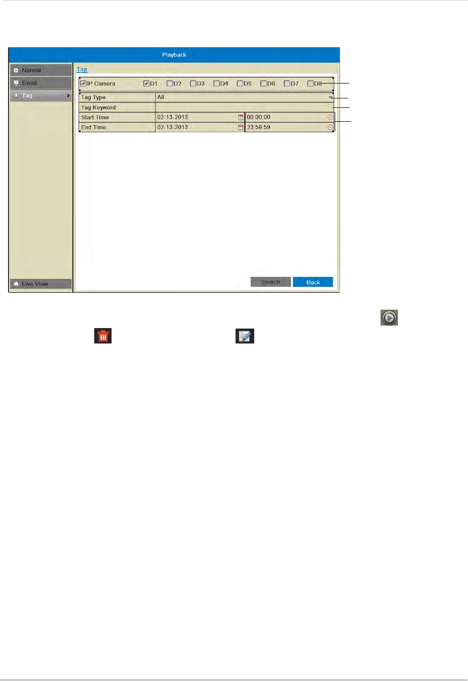
28
Playback
7Under End Time, select the end time for your search in the same way that you selected the
Start Time.
Select IP Cameras
Select Start and End times
Select tag type
Search for tag keyword
8Click Search to search for video. Video with applicable tags is shown. Click to playback a
video file, click to delete the tag, or click to edit a tag. Click Cancel to exit the search
results.
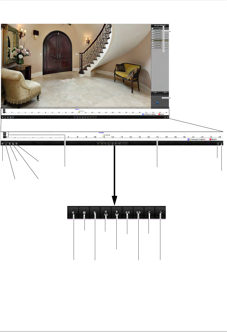
29
Playback
Using the On-Screen Playback Controls
Move the mouse to the right
side of the screen and click
the camera checkboxes to
select multiple channels for
playback
Use the calendar to select
the playback date,
double-click to select days
Mute
Start video
clip backup
Add
default
tag Zoom in/out
timeline
Add custom
tag
Manage
tags
Reverse
playback/pause
Stop
Play/pause
Skip
Back
30s
Skip
Forward 30s
Previous
day
Slow
Playback
Fast
Playback
Next day
Click to change playback
time
Playback time shown above
timeline:
Continuous & Motion (Blue)
Motion (Red)
Hide Playback
controls
Exit Playback
mode
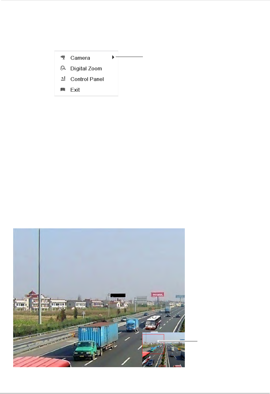
30
Playback
Using the Playback Quick Menu
The Playback Quick Menu allows you to select additional controls.
To access the Playback Quick Menu:
1Right-click during Playback mode.
Right-click to open the Playback
Quick Menu
The Playback Quick Menu contains the following options:
• Camera: Select the camera to view in Playback mode. Only available when one camera is
selected.
• Control Panel: Show/hide playback controls.
• Digital Zoom: Open Digital Zoom mode to get a closer look at recorded footage.
• Exit: Exit Playback Mode.
Using Digital Zoom in Playback Mode
Use Digital Zoom in Playback mode to get a closer look at recorded footage.
To use Digital Zoom in Playback Mode:
1Right-click to open the Playback Quick Menu and click Digital Zoom.
2If you are viewing more than one camera, click inside the camera you would like to zoom in
on. Otherwise, click on the screen to zoom in.
3To change the zoom area, click and drag in the box in the lower right corner of the screen.
Click and drag in the box to
change the zoom area
4Right-click to exit Digital Zoom.
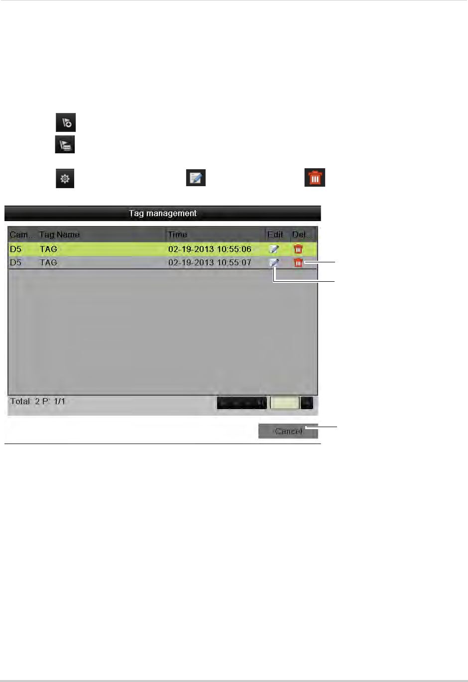
31
Playback
Tagging Video Footage
You can tag important moments in your video footage to keep track of events or people. For
example, you can tag when deliveries arrive or you can tag when people appear in the video.
You can use the Tag Search Menu to search for video using tags.
To tag video footage:
1During Playback, select one of the following:
• Click to tag the current playback time with the default tag.
• Click to tag the current playback time with a custom tag. Enter a name for your custom
tag and then click OK to confirm.
• Click to manage tags. Click to edit tags or click to delete tags. Click Cancel
when finished.
Delete tag
Edit tag
Exit tag management
(saves changes)
2To search for and playback video based on tags, see “Tag Search” on page 27.
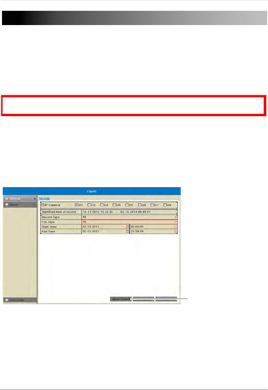
32
Backing Up Video
Backing Up Video
You can back up video to a USB flash drive (not included) or USB external hard drive (not
included) connected to the NVR.
NOTE: It is recommended to format the USB flash drive or external hard drive before using it
with the system. See below for details.
Formatting the USB Drive
ATTENTION: Formatting the USB flash drive or USB external hard drive will erase all
data on the drive.
To format the USB drive or external hard drive:
1Insert a USB flash drive (not included) or USB external hard drive (not included) into one of
the USB ports on the NVR.
2Right-click and click Menu.
3Enter the NVR’s user name (default: admin) and password (default: 000000) and click OK.
4Click Export then click Quick Export.
Click Quick Export
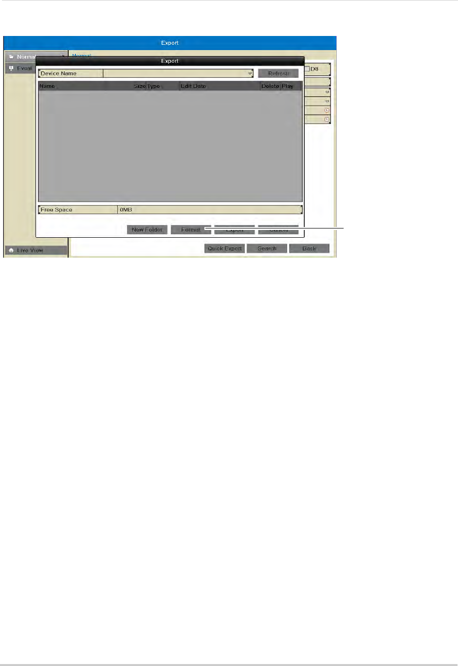
33
5Click Format. Click OK to confirm. Wait for formatting to complete.
Click Format
Using Quick Export
Quick Export allows you to quickly backup video if you know the exact times you would like
to backup.
To use Quick Export:
1Insert a USB flash drive (not included) or USB external hard drive (not included) into one of
the USB ports on the NVR.
2Right-click and click Menu.
3Enter the NVR’s user name (default: admin) and password (default: 000000) and click OK.
4Click Export.
5Configure the following:
• Under IP Camera, check the cameras you would like to backup. Check/un-check IP Camera
to select/deselect all cameras.
• Under Start Time, select the time to start the backup.
• Under End Time, select the time to end the backup.
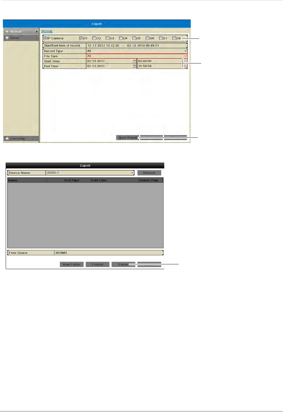
34
Backing Up Video
6Click Quick Export.
Click Quick Export
Select Cameras
Enter start and end
time
7Click Export to export all applicable video files.
Click Export
NOTE: You must have enough storage space on your backup device to save the video.
8Wait for the backup to complete and then click OK. To view backup files, see “Playing Back Up
Video Files” on page 36.
Using Search Export
Use Search Export to search for video files to backup.
To use Search Export:
1Insert a USB flash drive (not included) or USB external hard drive (not included) into one of
the USB ports on the NVR.
2Right-click and click Menu.
3Enter the NVR’s user name (default: admin) and password (default: 000000) and click OK.
4Click Export.
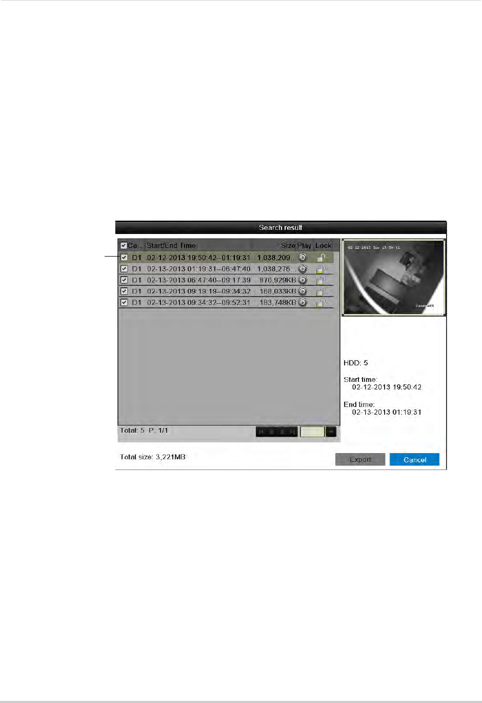
35
Backing Up Video
5Under IP Camera, check the cameras you would like to backup. Check/un-check IP Camera
to select/deselect all cameras.
6Under Record Type, select the type of recordings to search for: Continuous & Motion, Motion,
Manual, or All.
7Under File Type, select All, Unlocked, or Locked.
8Under Start Time, select the time to start the backup.
9Under End Time, select the time to end the backup.
10 Click Search. A list of videos appears based on your search criteria.
11 Check the files you would like to backup. Check/un-check at the top of the list to select/
deselect all files.
Check files to
select for backup
NOTE: You must have enough space on your USB drive to save all selected files. The total size
of the files selected appears below the list.
12 Click Export. Then, click Export, enter the system password (default: 000000), and click OK.
Wait for the backup to complete.
Using Video Clip Backup
Video clip backup allows you to select a duration of video during playback mode and save
it to a USB flash drive (not included).
To use Video Clip Backup:
1Insert a USB flash drive (not included) or USB external hard drive (not included) into one of
the USB ports on the NVR.
2From live viewing, right-click and then click All-Day Playback.
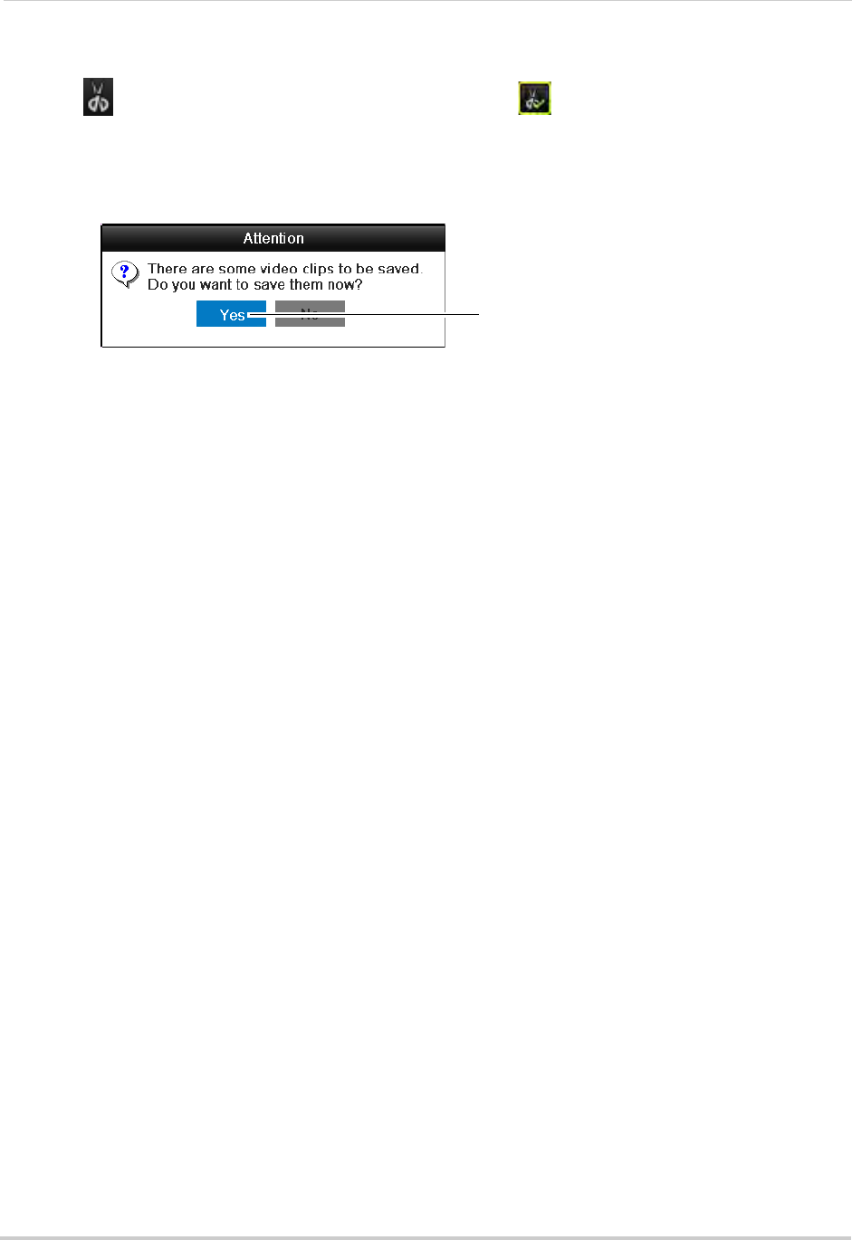
36
Backing Up Video
3Enter the NVR’s user name (default: admin) and password (default: 000000) and click OK.
4Click to when you want the video clip to start. Click when you want the video clip to
end.
5When you are done creating clips, right-click and click Exit to exit Playback mode. When you
exit, you are prompted to save your video clips. Click Yes.
Click Yes
6Click Export to begin backup. Enter the system password (default: 000000) and click OK to
begin backup. Wait for the backup to complete. To view backup files, see “Playing Back Up
Video Files” on page 36.
Playing Back Up Video Files
On PC, a Quick Player is automatically saved to the USB thumb drive (not included) or
external hard drive (not included) when backup files are saved. You may also use the client
software to play back video files (see “Opening Backup Video Files” on page 95).
NOTE: To play backup video files on Mac, visit www.lorextechnology.com for details.
Using the Quick Player to Playback Video Files
NOTE: The Quick Player is PC-compatible only.
To use the Quick Player:
1Connect the USB thumb drive (not included) or external hard drive (not included) to the
computer.
2Open the drive and double-click the Player.exe file.
3Click File>Open. Select the video file and click Open.
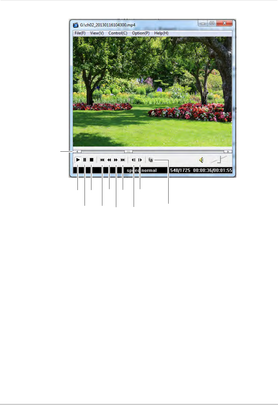
37
Backing Up Video
4Use the on-screen controls.
Play
Pause
Stop
Jump
to start
Slow
Fast
Forward
Jump
to end
Step
back
Step
forward
Capture
Click inside the bar to
select playback time
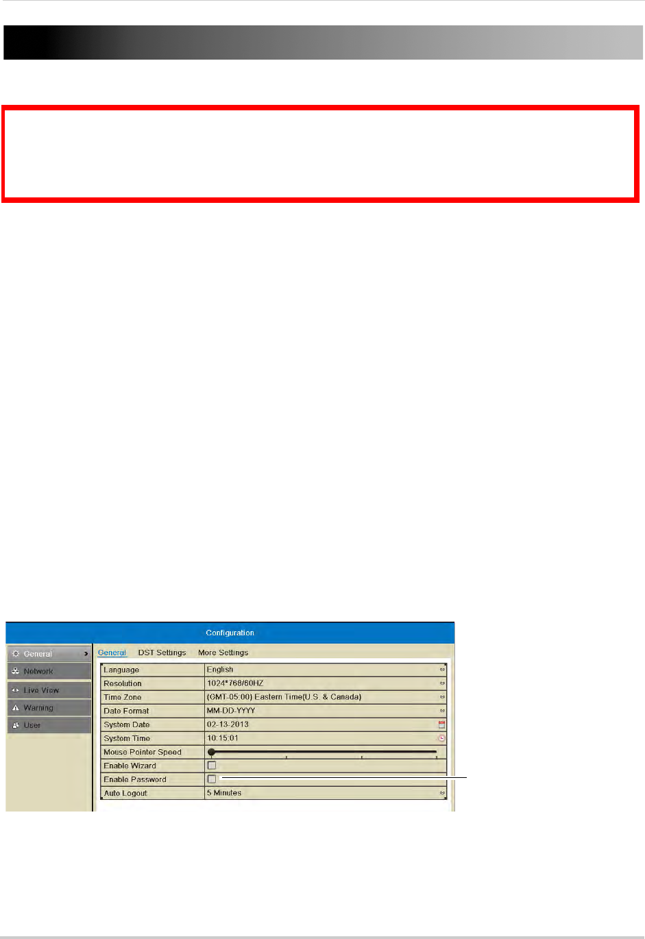
38
Managing Passwords
Managing Passwords
ATTENTION: By default, the system user name is admin and the password is 000000. Passwords
are enabled by default and are required to access the Main Menu.
The password is required to log into the system remotely using a computer or mobile device. You
will be prompted to create a custom password after you connect for the first time.
When you first startup your system, you are technically logged in as the admin (system
administrator) account. The system supports the following account types:
• Admin—system administrator: has full control of the system, and can change both
administrator and user passwords and enable/disable password protection.
• Operator—user account: has limited access to the system. Access permissions for operator
accounts can be customized by the admin account.
For security reasons, it is essential to create your own custom password.
Enabling/Disabling Passwords
When passwords are enabled, the system will require passwords to access playback or
system menus.
To enable passwords:
1Right-click and click Menu.
2Enter the system user name (default: admin) and password (default: 000000) and click Yes.
3Click Configuration.
4Check Enable Password to require passwords to access system menus or uncheck to disable
passwords.
Check Enable Password to
require passwords or uncheck
to disable
5Click Apply.
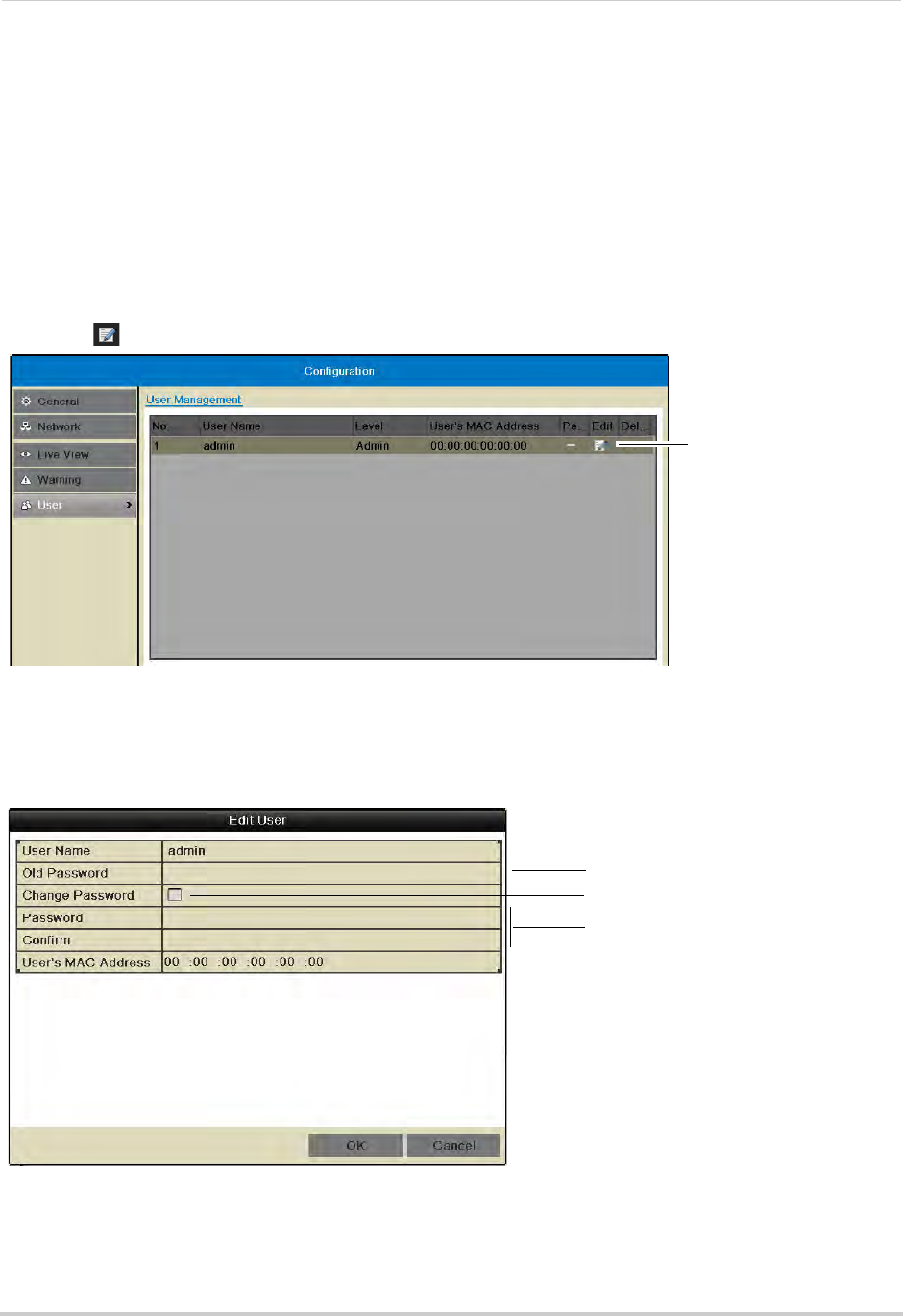
39
Managing Passwords
Managing User Accounts
Changing the Admin Account Password
For security, it is recommended to change the password for the admin account.
To change the admin account password:
1Right-click and click Menu.
2Enter the system user name (default: admin) and password (default: 000000) and click Yes.
3Click Configuration>User.
4Click next to admin.
Click to edit the admin
account
5Under Old Password, enter the current admin password (default: 000000).
6Check Change Password.
7Under Password and Confirm, enter the new admin password.
Enter existing password
(default: 000000)
Check Change Password
Enter new password
8Click OK to save changes. Right-click repeatedly to return to live viewing.
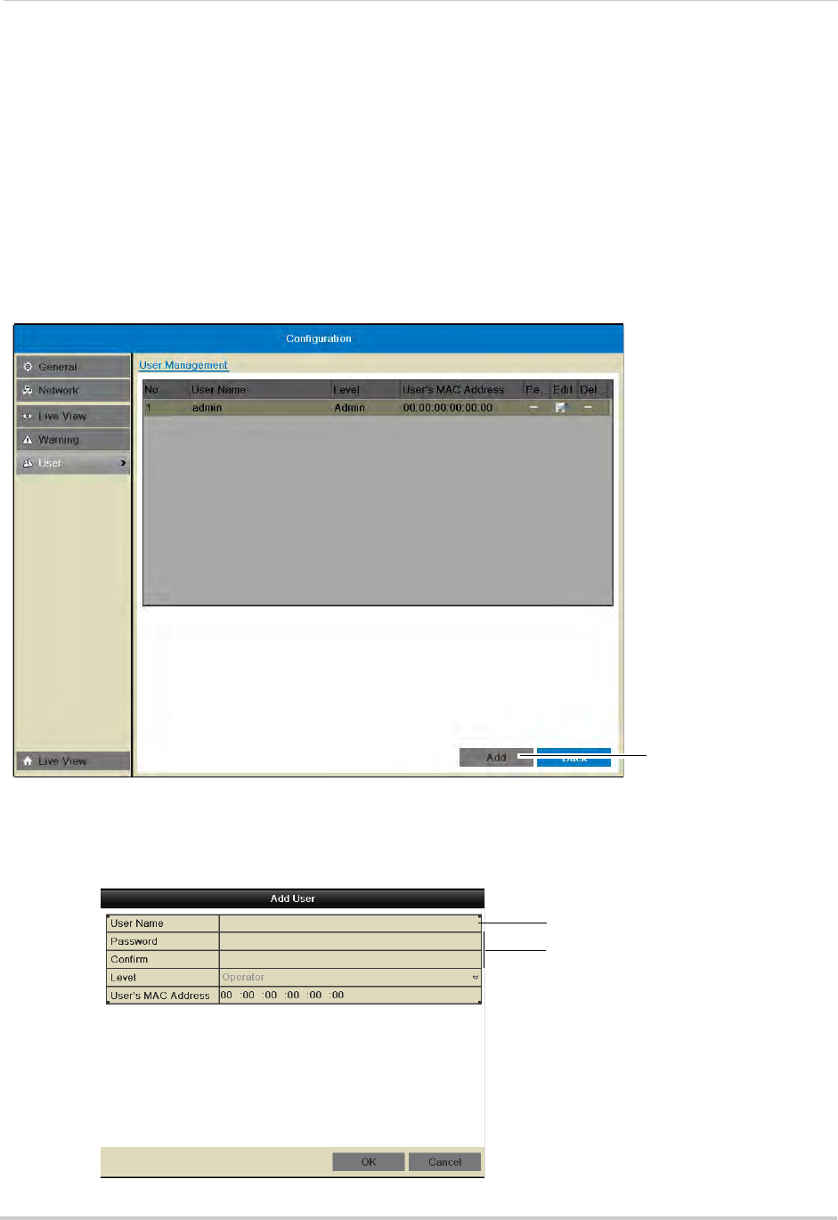
40
Managing Passwords
Adding Users
You can allow multiple users to log in to the system. When adding different users, you can
assign what menus they have access to. For example, you may want your friend to monitor
your system while you are away, while not giving full access to your system.
To add a new user:
1Right-click and click Menu.
2Enter the system user name (default: admin) and password (default: 000000) and click Yes.
3Click Configuration>User.
4Click Add. The Add User menu appears.
Click to add a new
user account
5Enter the desired User Name and Password for the user account. Re-enter the password
under Confirm.
NOTE: Do not change the User’s MAC Address field.
Enter User Name
Enter password
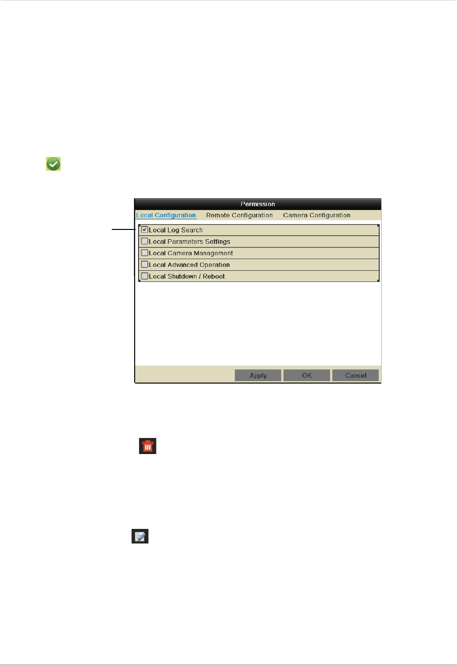
41
Managing Passwords
6Click OK to save the user account.
Configuring User Permissions
You can customize the menus that each user account may access.
To configure user permissions:
1Right-click and click Menu.
2Enter the system user name (default: admin) and password (default: 000000) and click Yes.
3Click Configuration>User.
4Click next to the user account you would like to configure.
5Check the permissions you would like to apply to the user.
Check permissions to
apply to the user
6Click Apply to save changes. Right-click repeatedly to return to live viewing.
Deleting Users
• In the User menu, click next to the user account you would like to delete. Click Yes to
confirm.
Editing Users
The admin can edit the user name and password of user accounts.
To edit user accounts:
1In the User menu, click next to the user account.
2Update the User Name as needed.
3Check Change Password to change the password. Enter the new password under Password
and Confirm.
4Click OK to save changes.
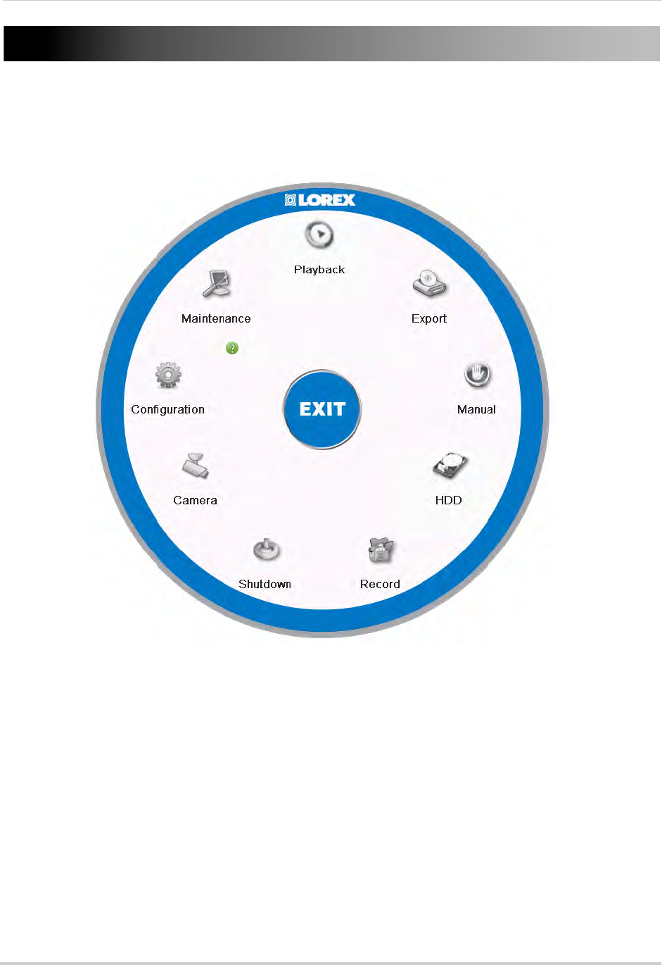
42
Using the Main Menu
Using the Main Menu
To open the Main Menu:
• Right-click to open the Quick Menu and click Menu. Enter the system user name (default:
admin) and password (default: 000000) and click Yes.
• Playback: Search and playback recorded video saved on the NVR. For details, see “Playback”
on page 23.
• Export: Back up video files to a USB flash drive or external hard drive. For details, see “Backing
Up Video” on page 32.
• Manual: Configure manual recording options. Select if cameras will use manual or scheduled
recording.
• HDD: Format hard drives and configure hard drive settings.
• Record: Configure recording settings and schedule.
• Camera: Configure camera image, motion detection, and other settings.
• Configuration: Configure system and network settings.
• Maintenance: View system info and device logs. Update firmware, reset to factory default
settings, and import/export system configuration.
• Shutdown: Log out, shutdown, or reboot the system.
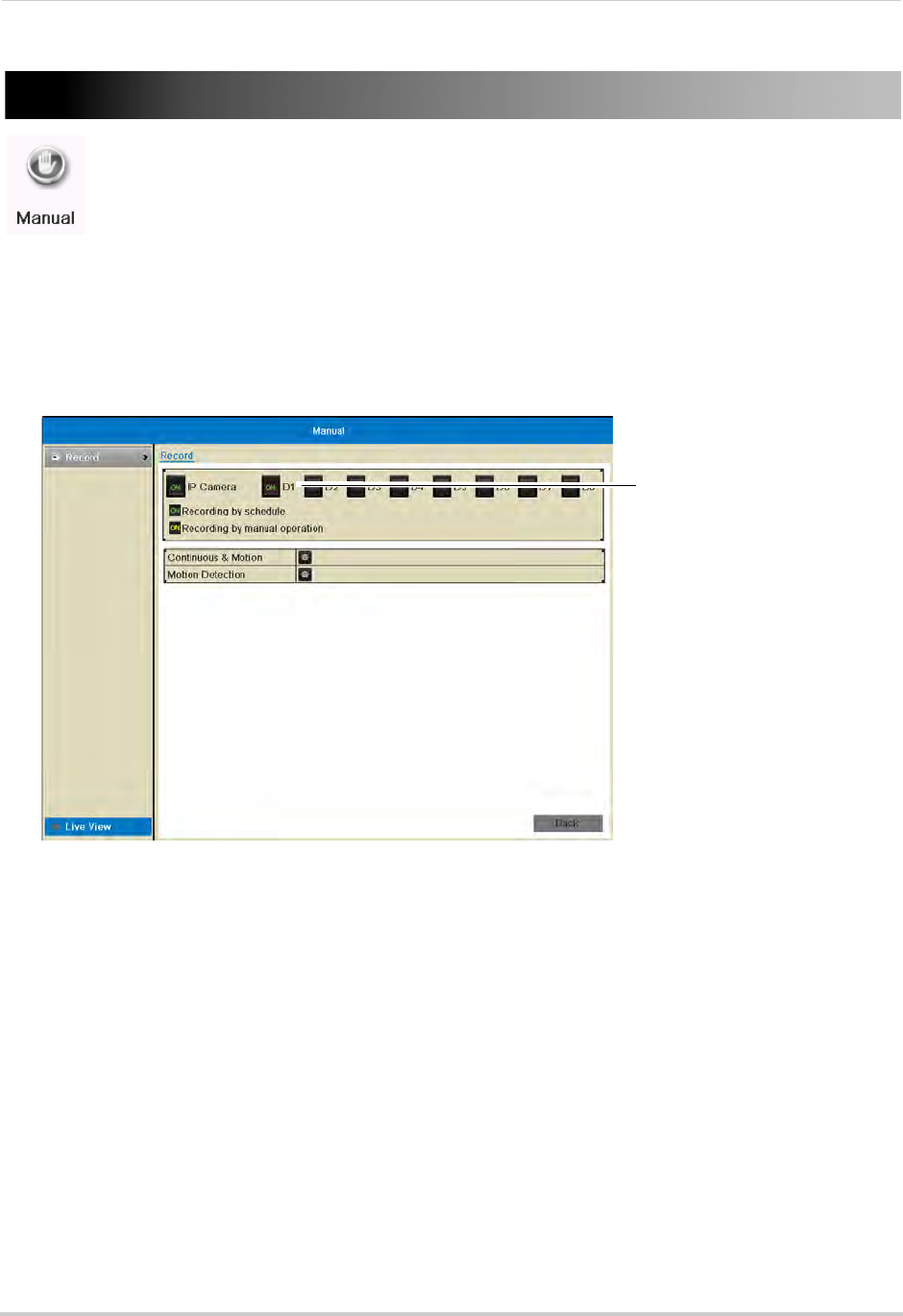
43
Manual
Manual
Configure manual recording options. Select if cameras will use manual or scheduled
recording.
Selecting Manual or Scheduled Recording
You can select if your cameras will record according to the schedule or according to manual
operation. For details on configuring the recording schedule, see “Configuring the
Recording Schedule” on page 50.
To select Manual or Scheduled Recording:
Click to select manual/
scheduled recording
1Right-click and then click Menu.
2Enter the system user name (default: admin) and password (default: 000000) and click Yes.
3Click Manual
4Click next to each camera to select one of the following:
• ON (Green): Use Schedule settings to determine recording. For details, see “Schedule” on
page 50.
• ON (Yellow): Record when manual recording is activated.
• OFF: Do not record.
5Right-click repeatedly to return to live view.
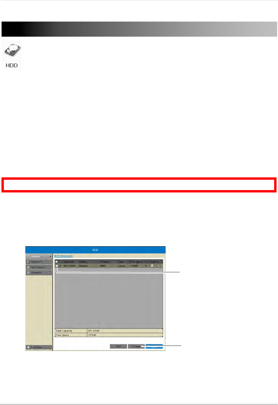
44
HDD
HDD
Format hard drives and configure hard drive settings.
The HDD Menu contains the following sub-menus:
• General
• Advanced
• HDD Detect
• Overwrite
General
Formatting the Hard Drive
If you replace the hard drive or install a new hard drive in the system, you must format it
before it can be used for recording.
To format the hard drive:
ATTENTION: Formatting the hard drive will erase all data on the drive.
1Right-click and then click Menu.
2Enter the system user name (default: admin) and password (default: 000000) and click Yes.
3Click HDD>General
4Check the hard drive that you would like to format.
Check the hard
drive
Click Format
5Click Format. Click OK to confirm. Wait for the formatting to complete. Right-click repeatedly
to return to live view.
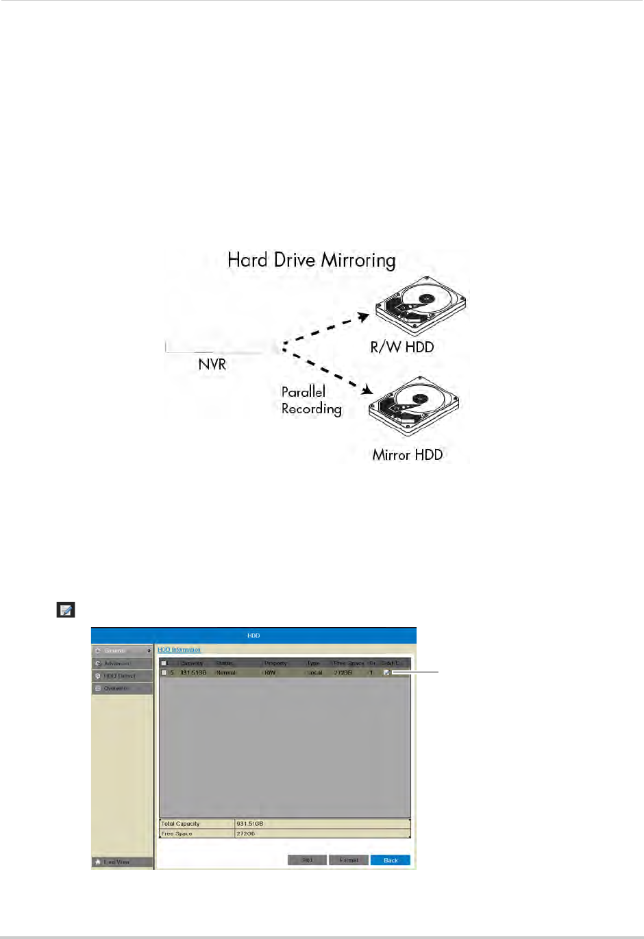
45
HDD
Configuring Hard Drive Type or Group
You can configure installed hard drives to perform the following functions:
• R/W (Recording Hard Drive): Normal recording hard drive.
• Read-only: Read-only hard drive. The NVR will not record to read-only hard drives.
• Mirror: Mirror hard drive. A mirror hard drive can be used to automatically backup video
footage recorded to the recording hard drive. When a mirroring hard drive is installed, the
NVR can be set to record cameras in parallel to both the recording hard drive and the mirror
hard drive. This way, the footage is automatically backed up if the recording hard drive fails.
NOTE: Mirror hard drive must be as large or larger than primary hard drive to backup all
recordings. Backup begins from when mirror hard drive is installed and configured.
To configure hard drive types on the NVR:
1If you are configuring a hard drive to be a mirroring hard drive, you must first format both the
recording hard drive and mirroring hard drive before you can set up hard drive mirroring.
For instructions on how to format hard drives, see “Formatting the Hard Drive” on page 44.
2Right-click and then click HDD.
3Click on the hard drive you would like to configure.
Click to configure
the hard drive
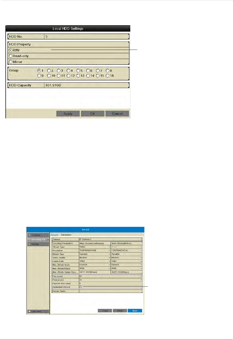
46
HDD
4Select the hard drive type to use for this hard drive: R/W, Read-only, or Mirror.
Select hard drive type
NOTE: You must have at least one R/W hard drive installed for the system to record.
5(Optional) If you are configuring the hard drive as R/W, you may select a hard drive group
under Group. Hard drive groups allow you to configure certain IP cameras to record to
different hard drives. For details, see “Configuring Recording Group Settings” on page 47.
6Click OK to save your changes. Right-click repeatedly to return to live view.
7If you are configuring a mirror hard drive, you must now enable redundant recording in your
cameras, to do so:
• Right-click and then click Record>Recording Setup.
• Under Camera, select the desired camera and check Mirror Record to enable redundant
recording to the mirror hard drive.
• Repeat for any additional cameras or use Copy to copy redundant recording settings to all
cameras.
• Click Apply to save changes. Right-click repeatedly to return to live view
Check to enable recording
to the mirror hard drive
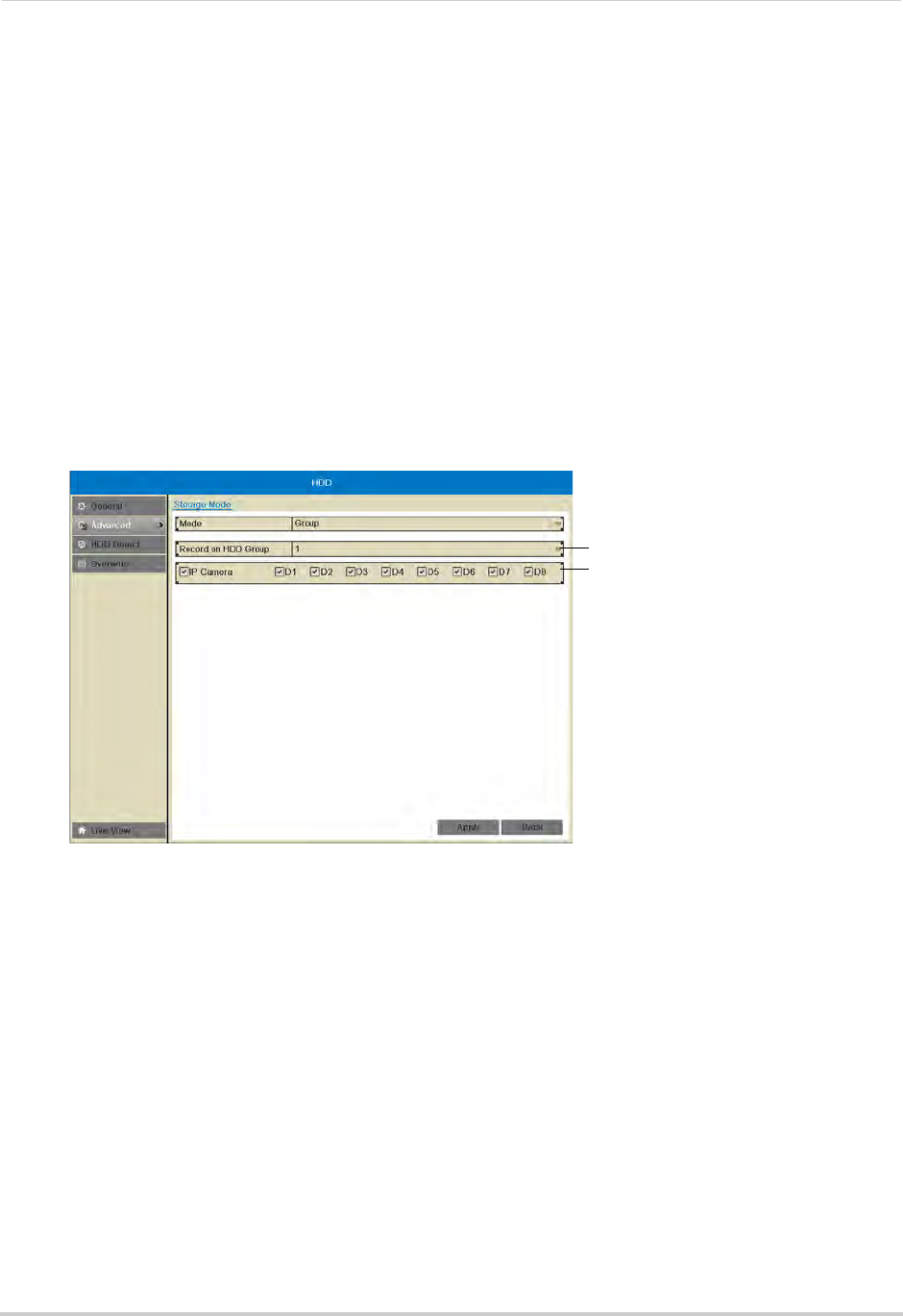
47
HDD
Advanced
Configuring Recording Group Settings
Use recording group settings if you want to specify which hard drive group your cameras
will record to.
NOTE: You must have a second hard drive (not included) installed to use recording group
settings.
To configure recording group settings:
1Right-click and then click Menu.
2Enter the system user name (default: admin) and password (default: 000000) and click Yes.
3Click HDD>Advanced.
4Under Record on HDD Group, select the hard drive group you would like to configure.
Select hard drive group
Select cameras to record to
selected group
NOTE: To assign your hard drives to groups, see “Configuring Hard Drive Type or Group” on
page 45.
5Check the cameras you would like to record to the selected hard drive group.
6Click Apply to save changes. Right-click repeatedly to return to live view.
HDD Detect
NOTE: The options in the HDD Detect sub-menu are for advanced users. It is recommended to
leave all settings on their default values.
Setting S.M.A.R.T. Settings and Running S.M.A.R.T. Checks on the Hard Drive
The device supports S.M.A.R.T. and Bad Sector Detection. S.M.A.R.T. (Self-Monitoring,
Analysis and Reporting Technology) is a monitoring system for hard drives that detects and
reports potential reliability issues to help anticipate hard drive failure.
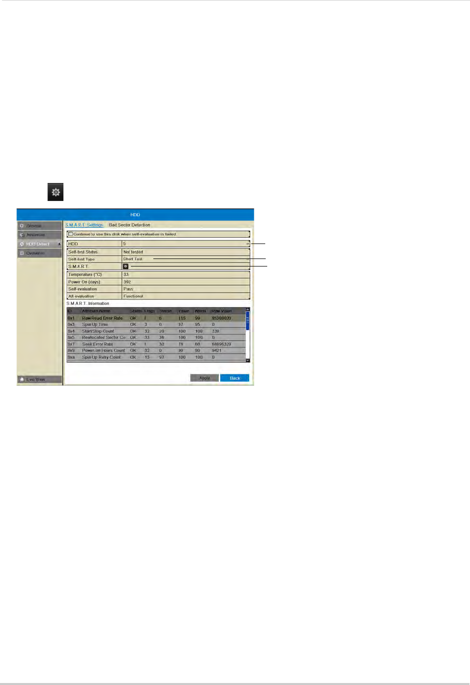
48
HDD
To set S.M.A.R.T. settings:
1Right-click and then click Menu.
2Enter the system user name (default: admin) and password (default: 000000) and click Yes.
3Click HDD>HDD Detect.
4Under HDD, select the hard drive you would like to check.
NOTE: You can see the HDD No. of installed hard drives under the HDD>General sub-menu.
5Under Self-test Type, select the type of S.M.A.R.T. test you would like to run.
6Click next to S.M.A.R.T. to begin the S.M.A.R.T. test. Wait for the test to complete.
Select S.M.A.R.T. test type
Click to start test
Select hard drive
Checking the Hard Drive for Errors
The NVR can check the hard drive for errors or bad sectors.
To check the hard drive for errors:
1Right-click and then click Menu.
2Enter the system user name (default: admin) and password (default: 000000) and click Yes.
3Click HDD>HDD Detect>Bad Sector Detection.
4Under HDD, select the hard drive you would like to check.
NOTE: You can see the HDD numbers of installed hard drives under the HDD>General
sub-menu.
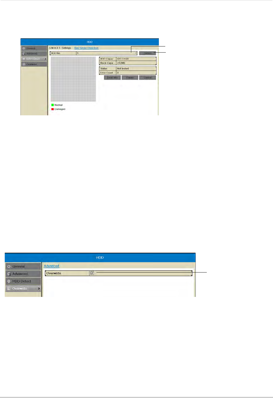
49
HDD
5Click Detect to begin the scan. The NVR will scan the hard drive for bad sectors and show the
results in the chart. Green blocks are normal sectors, and red blocks are damaged sectors.
Select hard drive
Start bad sector test
The hard drive scan may take up to a couple hours. If you exit the Bad Sector Detection
sub-menu, the scan will be paused.
Overwrite
Enabling/Disabling Overwrite
Overwrite is enabled by default. When overwrite is enabled, the NVR will begin to overwrite
the oldest video footage when the hard drive is full. If Overwrite is not enabled, the NVR will
stop recording when the hard drive is full.
To enable/disable overwrite:
1Right-click and then click Menu
2Enter the system user name (default: admin) and password (default: 000000) and click Yes.
3Click HDD>Overwrite.
4Check Overwrite to enable overwrite or un-check to disable.
Check to enable
Overwrite
5Click Apply to save your settings.

50
Record
Record
Configure recording settings and schedule.
The Record menu contains the following sub-menus:
• Schedule
• Encoding Settings
• Holiday
Schedule
Configuring the Recording Schedule
Use the recording schedule to configure when cameras will use continuous or motion
detection recording.
To configure the recording schedule:
1Right-click and then click Menu.
2Enter the system user name (default: admin) and password (default: 000000) and click Yes.
3Click Record.
4Under Camera, select the camera you would like to configure.
5Ensure Enable Schedule is checked.
6Select the recording type to add to the schedule on the right side of the screen:
• Continuous & Motion: Camera will record at all times and mark motion events.
• Motion (Motion Detection Recording only): Camera will record when motion is detected only.
• None: Camera will not record.
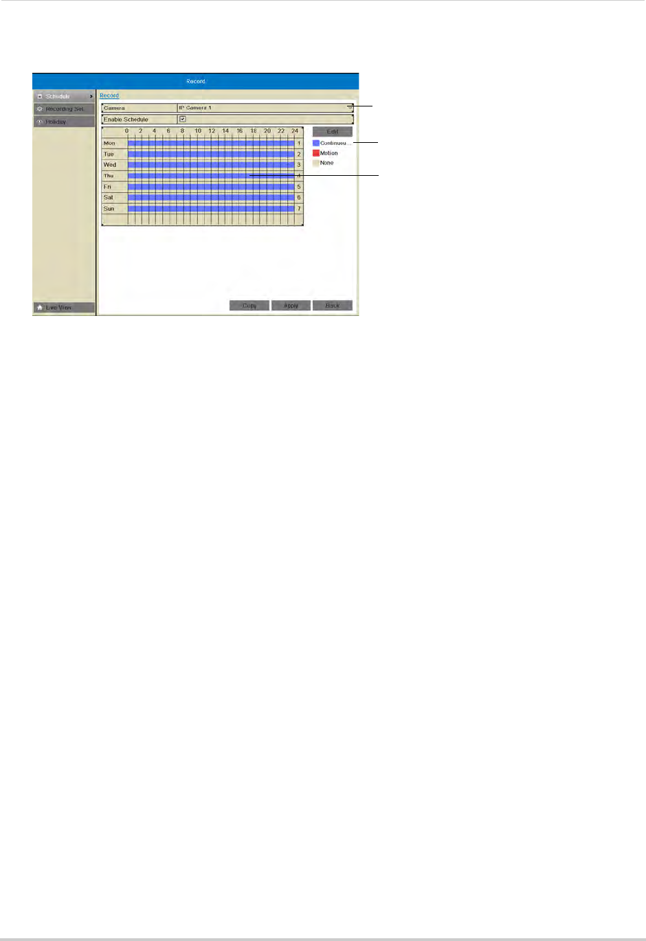
51
Record
7Click and drag inside the schedule to apply the currently selected recording type.
Click to select a schedule type
Click and drag to add the recording
type to the schedule
Select camera
8(Optional) To copy the schedule to other cameras, click Copy. Check cameras you would like
to copy the schedule to. Check/un-check IP Camera to copy the schedule to all cameras.
Click OK to copy the schedule.
9Click Apply to save changes. Right-click repeatedly to return to live view.
Recording Setup
Use the Recording Setup to configure recording and streaming parameters for your
cameras such as the resolution, frame rate, network bandwidth, and event pre and
post-recording durations.
The Encoding Settings are set separately for Continuous and Event (motion) recording.
They may also be set for remote streaming to a computer or mobile device through the
Substream tab.
Configuring Recording Resolution, Frame Rate, and Image Quality
The resolution, frame rate, and image quality can be set separately for each camera, as
well as for continuous and motion recording.
To configure the recording resolution, frame rate, and image quality:
1Right-click and then click Menu.
2Enter the system user name (default: admin) and password (default: 000000) and click Yes.
3Click Record>Recording Setup.
4Under Camera, select the camera you would like to configure.
5Configure the following settings under Mainstream (Continuous) to set the parameters for
continuous recording:
• Under Resolution, select the recording resolution of the camera: 1280*720 (720P) or
1920*1080 (1080P).
• Under Video Quality, select the video quality from Lowest to Highest.
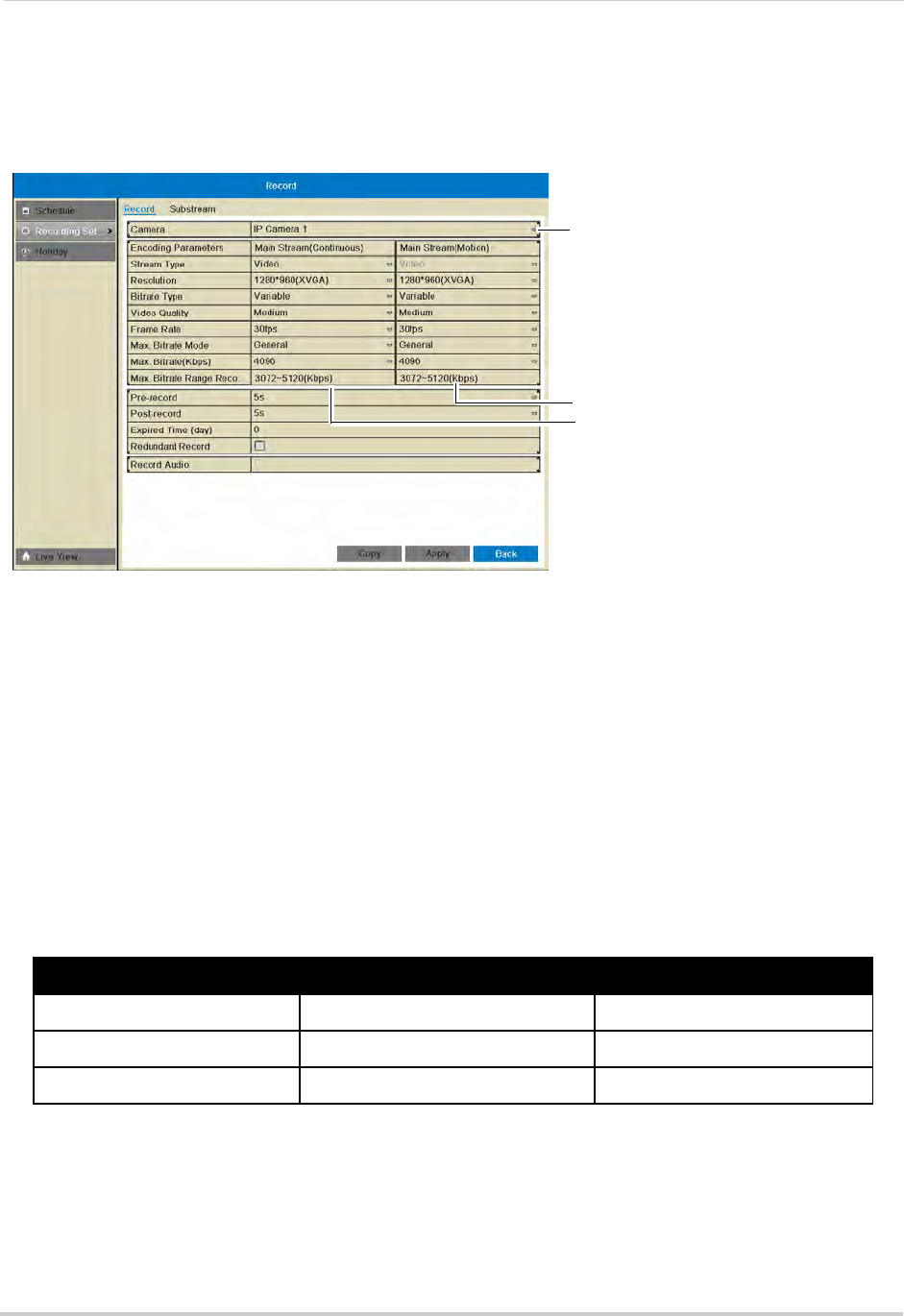
52
Record
• Under Frame Rate, select the recording frame rate.
• Under Max Bitrate, select the bitrate that will be used for video streaming in Kbps. It is
recommended to select a value within the range shown under Max. Bitrate Range
Recommended.
Enter image quality settings for
continuous recording
Enter image quality settings for
motion recording
Select camera
6Configure the above settings under Mainstream (Motion) to set the parameters for motion
recording.
7(Optional) Use the Copy button to copy the selected settings to other channels. A warning
message may appear when copying settings to unconnected channels, but the NVR will copy
settings to all connected channels.
8Click Apply to save changes. Right-click repeatedly to return to live viewing.
NOTE: If you get a "Bandwidth Exceeded" message, it is because you have set the combined
bitrate or framerate for all your cameras higher than the NVR can process. It is
recommended to set the bitrate and framerate to the following settings, based on the
number of channels your NVR has:
Recommended Frame Rate and Bitrate per Number of Channels
Number of Channels Frame Rate (frames per second) Bitrate (Kbps)
4 channels 30 8192
8 channels 30 4096
16 channels 15 3200
Configuring the Pre-Record and Post-Record Times
The NVR supports pre-recording to record video from before events (such as motion or
video loss) occur. The Pre-Record time determines how long the NVR will record before an
event occurs.
The Post-Record time determines how long the NVR will record after an event occurs.
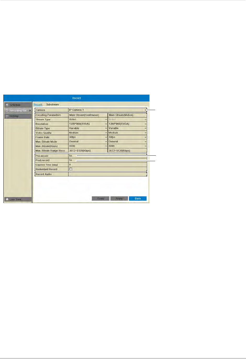
53
Record
To configure the Pre-Record and Post-Record times:
1Right-click and then click Menu.
2Enter the system user name (default: admin) and password (default: 000000) and click Yes.
3Click Record>Recording Setup.
4Under Camera, select the camera you would like to modify.
5Under Pre-record, select the time the NVR will record before an event.
6Under Post-record, select the time the NVR will record after an event.
Select post-record time
Select pre-record time
Select camera
7Click Apply to save changes. Right-click repeatedly to return to live view.
Configuring Substream Settings
Substream settings allow you to configure the video quality settings for streaming to a
computer or mobile device. The substream allows you to conserve Internet bandwidth for
connections over the LAN or Internet while still ensuring high quality recordings.
NOTE: Increasing the substream settings may affect the performance of the video stream,
depending on bandwidth available.
To configure substream settings:
1Right-click and then click Menu.
2Enter the system user name (default: admin) and password (default: 000000) and click Yes.
3Click Record>Recording Setup>Substream.
4Under Camera, select the camera you would like to configure.
5Under Resolution, select the resolution to use for streaming: 704*576(4CIF), 352*288(CIF),
320*240(QVGA).
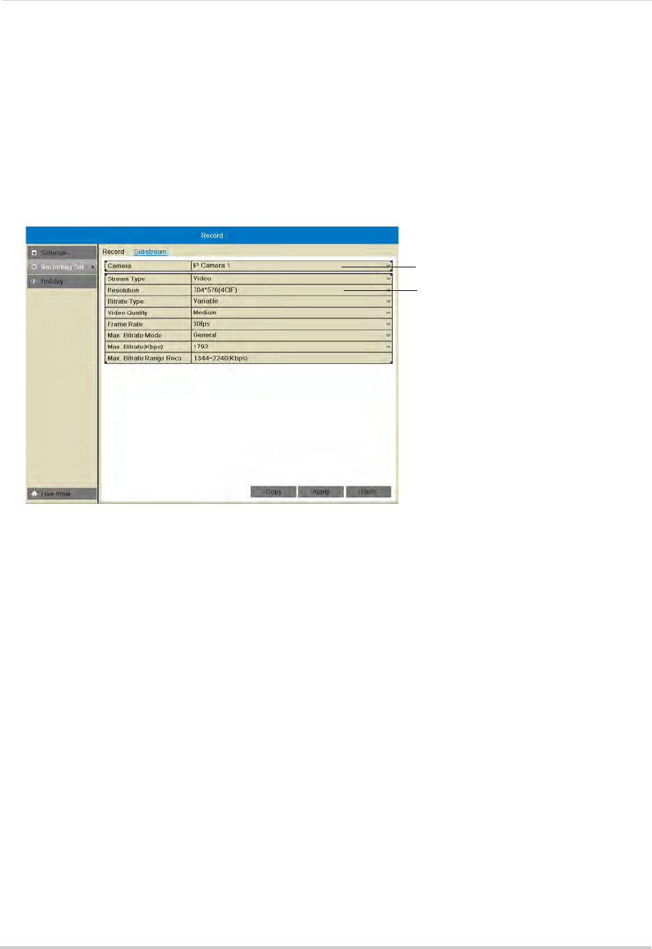
54
Record
6Under Bitrate Type, select Variable (recommended) for variable bitrate or Constant for
constant bit rate.
• If you select Variable, select the Video Quality between Highest and Lowest.
7Under Frame Rate, select the frame rate for streaming.
8Under Max. Bitrate Mode, select General to use one of the pre-set options or Customize to
manually enter the bitrate.
9Under Max Bitrate (Kbps), enter the desired bitrate in Kbps.
Select camera
Adjust sub-stream
quality settings
10 Click Apply to save changes. Right-click repeatedly to return to live view.
Holiday
Configuring Holidays
You may set specific days or ranges of days as holidays. Holidays will have special
recording settings that can be configured in the schedule.
To configure holidays:
1Right-click and then click Menu.
2Enter the system user name (default: admin) and password (default: 000000) and click Yes.
3Click Record>Holiday.
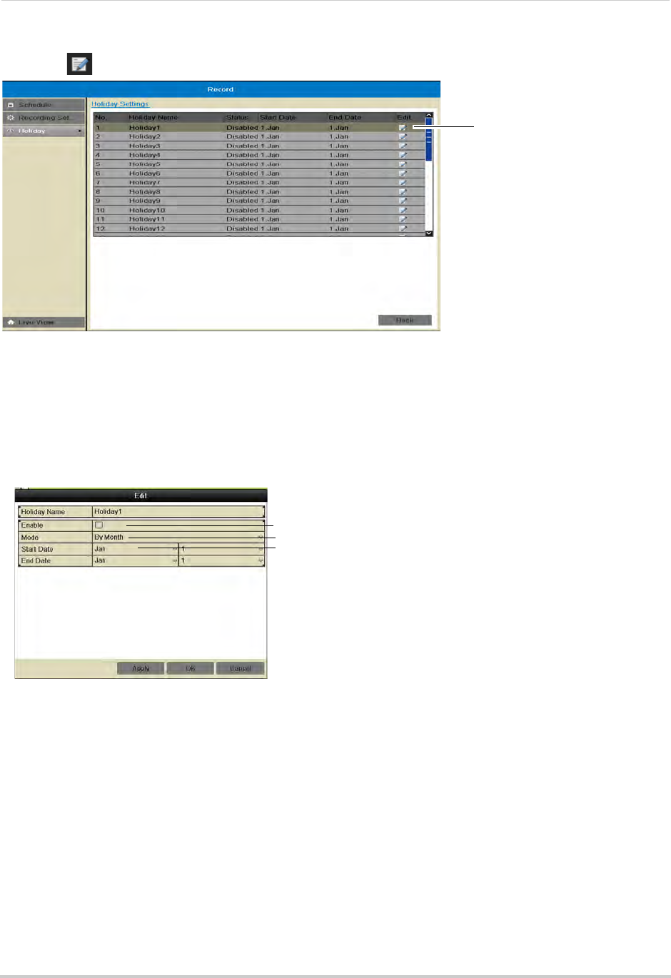
55
Record
4Click next to the holiday you would like to configure.
Click to edit
holidays
5Check Enable to enable the holiday or un-check to disable.
6Select the Start Date and End Date for the holiday. If you want the holiday to be one day only,
select the same day for both Start Date and End Date.
• Use the Mode to select the date using different methods: By Date allows you to use a calendar
to select the date, By Month uses drop-down menus, and By Week allows you to select the
week and day of the week that will be used.
Check to enable holiday
Select the date for the holiday using different methods
Select the Start and End Date for the holiday
7Click OK to save changes. Once you have enabled holidays, a Holiday line is added to the
schedule. You must configure the schedule to record during holidays. For details, see
“Configuring the Recording Schedule” on page 50.
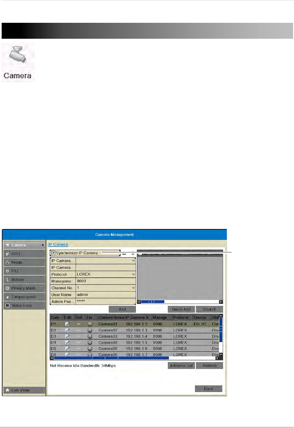
56
Camera
Camera
Configure camera image and motion detection settings.
The Camera menu contains the following sub-menus:
• Camera
• OSD
• Image
• PTZ (not supported)
• Motion
• Privacy Mask
• Tamper-proof
• Video Loss
Camera
The Camera sub-menu (Menu>Camera) allows you to manage IP cameras connected over
the LAN or PoE ports. For details on connecting IP cameras over the LAN, see “Connecting
Cameras over the Local Network” on page 9.
NOTE: If you are having issues connecting your IP cameras to the NVR using the PoE ports,
ensure Synchronize IP Camera is checked.
Ensure Syncronize IP
camera is checked
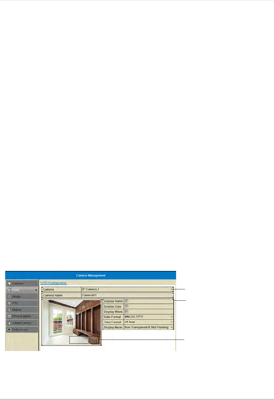
57
Camera
OSD
The OSD sub-menu allows you to configure custom names for your cameras or configure
the on-screen text shown for your cameras.
Configuring the On-Screen Display and Camera Name
You can customize the appearance of on-screen text.
To configure the on-screen display:
1Right-click and click Menu.
2Enter the system user name (default: admin) and password (default: 000000) and click Yes.
3Click Camera>OSD.
4Under Camera, select the camera you would like to modify.
5Under Camera Name, enter the desired camera name.
6Check Display Name to show the camera name.
7Check Display Date to show the current date and time.
8Check Display Week to show the day of the week in the date.
9Under Date Format, select the desired date format.
10 Under Time Format, select 24-hour or 12-hour time.
11 Under Display Mode, select Non-Transparent and Not Flashing to have the on-screen text
shown at all times, or select Non-Transparent and Flashing to have the on-screen text flash
on the screen.
12 Click and drag the boxes in the image preview to change the position of the on-screen display
text. The yellow box controls the position of the time and date, and the red box controls the
position of the camera name.
Select the camera
Configure on-screen text
Camera01 Click and drag messages to
adjust their position
NOTE: The position of the on-screen text will not update until you click Apply.
13 Click Apply to save your changes. Right-click repeatedly to return to live view.
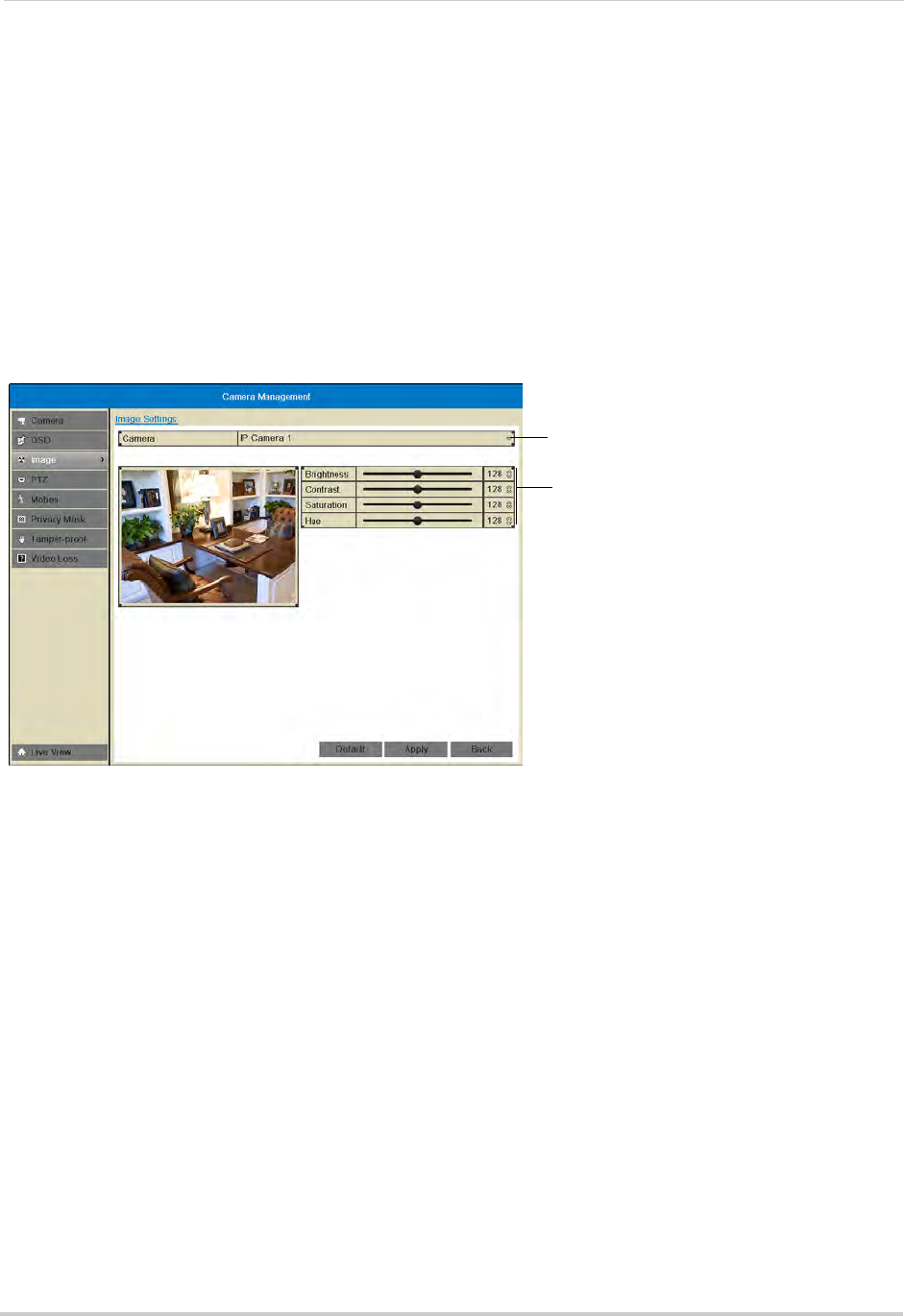
58
Camera
Image
Configuring Camera Image Settings
1Right-click and then click Menu.
2Enter the system user name (default: admin) and password (default: 000000) and click Yes.
3Click Camera>Image.
4Under Camera, select the camera you would like to adjust.
5Use the sliders to adjust the Brightness, Contrast, Saturation, and Hue. Note that it may take
a couple seconds for changes to occur.
Select camera
Adjust image settings
6Click Apply to save changes.
Motion
Configuring Motion Detection Settings
By default, motion detection is enabled on all connected cameras. You can enable/disable
cameras for motion detection.
You can also enable/disable parts of the image for motion detection. For example, you can
disable motion detection where your camera overlooks a public street but enable motion
detection to trigger when someone enters your driveway.
To configure motion detection settings:
1Right-click and click Menu.
2Enter the system user name (default: admin) and password (default: 000000) and click Yes.
3Click Camera>Motion.
4Under Camera, select the camera you would like to configure.
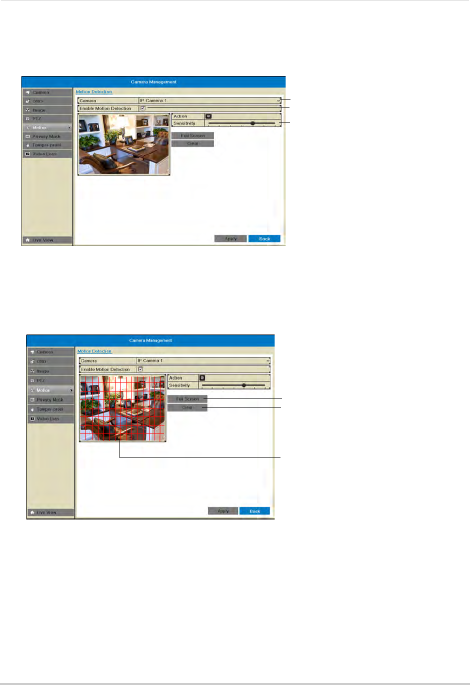
59
Camera
5Check Enable Motion Detection to enable motion detection or un-check to disable.
6Adjust the Sensitivity slider to configure motion detection sensitivity.
Select camera
Enable motion detection
Adjust motion detection senstiivity
7In the image area, configure motion detection areas:
• Areas where the grid is filled in are enabled for motion detection.
• Click and drag to enable/disable areas of the screen for motion detection.
• Click Full Screen to enable the entire area for motion detection.
• Click Clear to disable the entire area for motion detection.
Click and drag to enable/
disable motion areas
Enable whole screen
Disable whole screen
8Click Apply to save changes. Right-click repeatedly to return to live view.
Configuring Motion Detection Alarm Settings
You can configure the alarm actions that occur when motion detection is triggered.
To configure motion detection alarm settings:
1Right-click and click Menu.
2Enter the system user name (default: admin) and password (default: 000000) and click Yes.
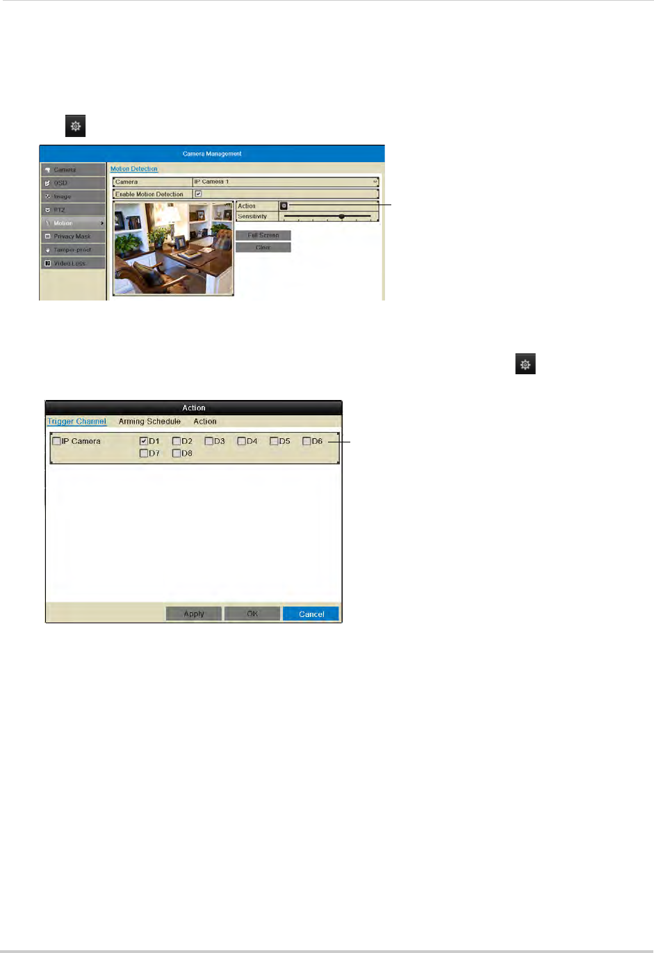
60
Camera
3Click Camera>Motion.
4Under Camera, select the camera you would like to configure.
5Click under Action to open the Action menu.
Click to open the Action menu
6In the Trigger Channel tab, select which channels that will start to record when motion
detection is triggered on the selected channel. For example, if you want channels 1 and 2 to
record when motion is detected on channel 1, select channel 1 and click , then check D1
and D2 in Trigger Channel.
Check channels that will record when
the selected channel detects motion
7In the Arming Schedule tab, configure the times of day you would like motion detection to be
enabled for the selected channel. By default, motion detection is enabled 24/7.
• Under Week, select the day of the week you would like to configure.
• Configure up to 8 time periods per day when motion detection will be enabled.
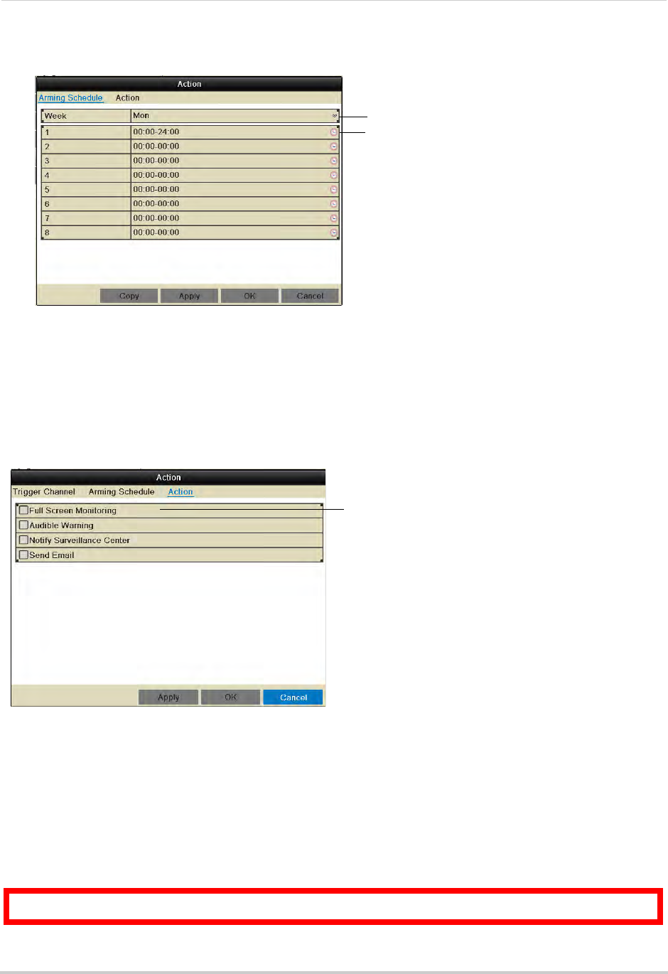
61
Camera
• Click Copy to copy the currently selected day’s schedule to other days of the week.
Select day of the week
Enter times when motion will be
enabled
8In the Action tab, check the alert actions that you want to occur when motion is detected on
the selected channel.
• Full Screen Monitoring: The selected channel will open in full screen.
• Audible Warning: System will beep.
• Notify Surveillance Center: An alert will be sent to the client software.
• Send Email: An alert email will be sent. Note that you must set up email alerts before the
system will send them. For details on email alerts, see “Configuring Email Alerts” on page 70.
Check alert actions
9Click Apply to save changes. Click OK.
10 Click Apply to save changes. Right-click repeatedly to return to live view.
Privacy Mask
Configuring Privacy Masks
A privacy mask allows you to block out portions of the image with a black square.
ATTENTION: Areas covered in privacy masks are not visible in recordings.
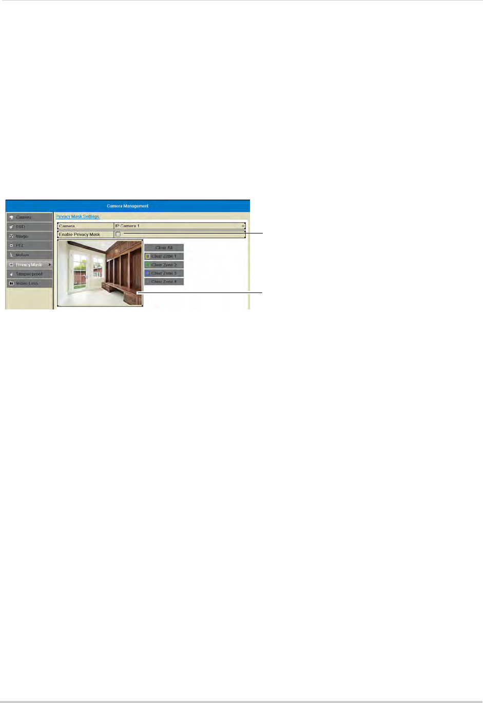
62
Camera
To configure privacy masks:
1Right click and click Menu.
2Enter the system user name (default: admin) and password (default: 000000) and click Yes.
3Click Camera>Privacy Mask.
4Under Camera, select the camera you would like to configure.
5Check Enable Privacy Mask to enable privacy masks or un-check to disable.
6Click and drag on the image to add privacy masks. You can configure up to 4 privacy masks
per camera.
Check to enable privacy masks
Click and drag to add privacy mask areas
• Click the Clear buttons if you need to delete a privacy mask.
7Click Apply to save changes.
Tamper-proof
Configuring Tamper-proof Alarms
Tamper-proof alarms occur if an intruder attempts to tamper with the camera by covering
the lens.
To configure tamper-proof alarms:
1Right click and click Menu.
2Enter the system user name (default: admin) and password (default: 000000) and click Yes.
3Click Camera>Tamper-proof.
4Under Camera, select the camera you would like to configure.
5Check Enable Tamper-proof to enable tamper-proof alarms or un-check to disable.
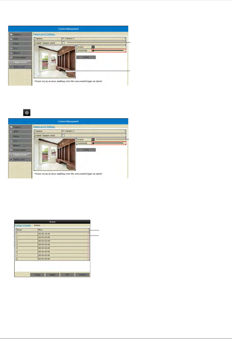
63
Camera
6Use the Sensitivity slider to select the sensitivity for tamper-proof alarms.
Check to enable Tampering alarms
Click and drag to select tamper-proof area
7Click and drag inside the image to select the area where you would like to detect video
tampering. It is recommended to place the area in the middle of the image.
8Click under Action to open the Action menu.
Click to open the action menu
9In the Arming Schedule tab, configure the times of day you would like tamper-proof alarms
to be enabled for the selected camera.
• Under Week, select the day of the week you would like to configure.
• Configure up to 8 time periods per day when motion detection will be enabled.
• Click Copy to copy the currently selected day’s schedule to other days of the week.
Select day of the week
Enter times when tamper alarms will
be enabled
10 In the Action tab, check the alert actions that you want to occur if the lens is covered on the
selected channel.
• Full Screen Monitoring: The selected channel will open in full screen.
• Audible Warning: System will beep.
• Notify Surveillance Center: An alert will be sent to the client software.
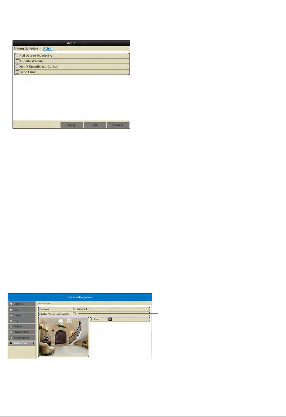
64
Camera
• Send Email: An alert email will be sent. Note that you must set up email alerts before the
system will send them. For details on email alerts, see “Configuring Email Alerts” on page 70.
Select tamper alarm alerts
11 Click Apply to save changes. Click OK.
12 Click Apply to save changes. Right-click repeatedly to return to live view.
Video Loss
Configuring Video Loss Alarm Settings
Video Loss Alarms occur if the connection between the NVR and cameras is lost (for
example, if the ethernet cable is disconnected).
To configure video loss alarms:
1Right-click and then click Menu.
2Enter the system user name (default: admin) and password (default: 000000) and click Yes.
3Click Camera>Video Loss.
4Under Camera, select the camera you would like to configure.
5Check Enable Video Loss Alarm to enable video loss alarms or un-check to disable.
Check to enable video loss
alarms
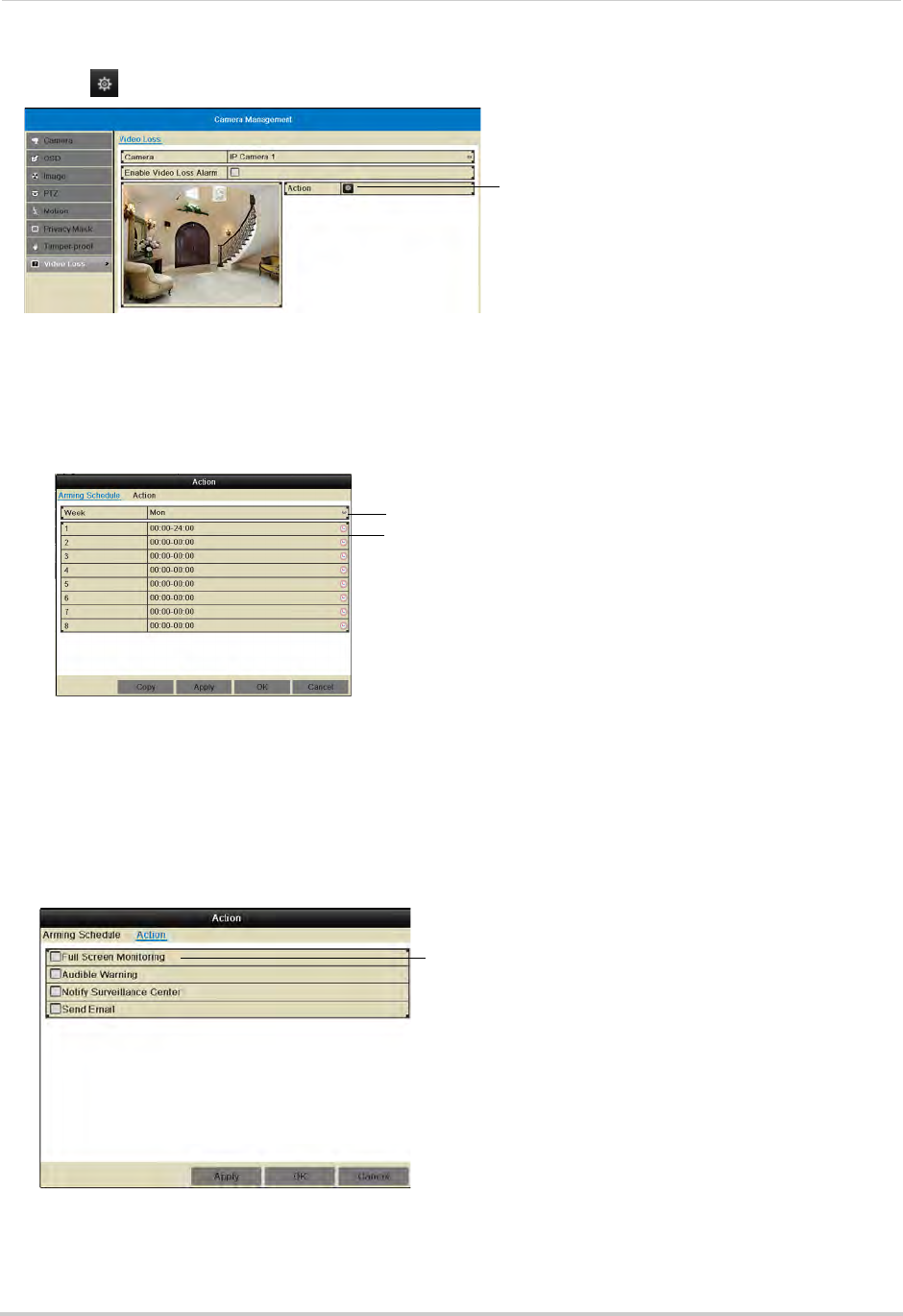
65
Camera
6Click under Action to open the Action menu.
Click to open the Action menu
7In the Arming Schedule tab, configure the times of day you would like video loss alarms to be
enabled for the selected camera.
• Under Week, select the day of the week you would like to configure.
• Configure up to 8 time periods per day when motion detection will be enabled.
• Click Copy to copy the currently selected day’s schedule to other days of the week.
Select day of the week
E n t e r t i m e s w h e n v i d e o l o s s a l a r m s w i l l
be enabled
8In the Action tab, check the alert actions that you want to occur if video loss occurs on the
selected channel.
• Full Screen Monitoring: The selected channel will open in full screen.
• Audible Warning: System will beep.
• Notify Surveillance Center: An alert will be sent to the client software.
• Send Email: An alert email will be sent. Note that you must set up email alerts before the
system will send them. For details on email alerts, see “Configuring Email Alerts” on page 70.
Select video loss alerts
9Click Apply to save changes. Click OK.
10 Click Apply to save changes. Right-click repeatedly to return to live view.
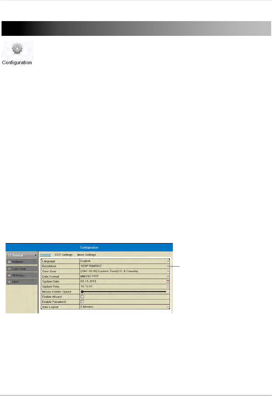
66
Configuration
Configuration
Configure system and network settings.
The Configuration Menu contains the following sub-menus:
• General
• Network
• Live View
• Warning
• User
General
• For instructions on setting the date and time, see “Setting the Date and Time” on page 19.
• For instructions on enabling system passwords or configuring user accounts, see “Managing
Passwords” on page 38.
Setting the Display Resolution
You can set the display resolution for your VGA or HDMI monitor.
To set the display resolution:
1Right-click and click Menu.
2Enter the system user name (default: admin) and password (default: 000000) and click Yes.
3Click Configuration.
4Under Resolution, select the correct resolution for your monitor.
Select the correct resolution for your
monitor
5Click Apply to save changes. The resolution will update. Click OK to confirm.
NOTE: If you do not click OK within 15 seconds, the resolution will reset to the previously selected
setting.
Setting the Mouse Pointer Speed
1Right-click and click Menu>Configuration.
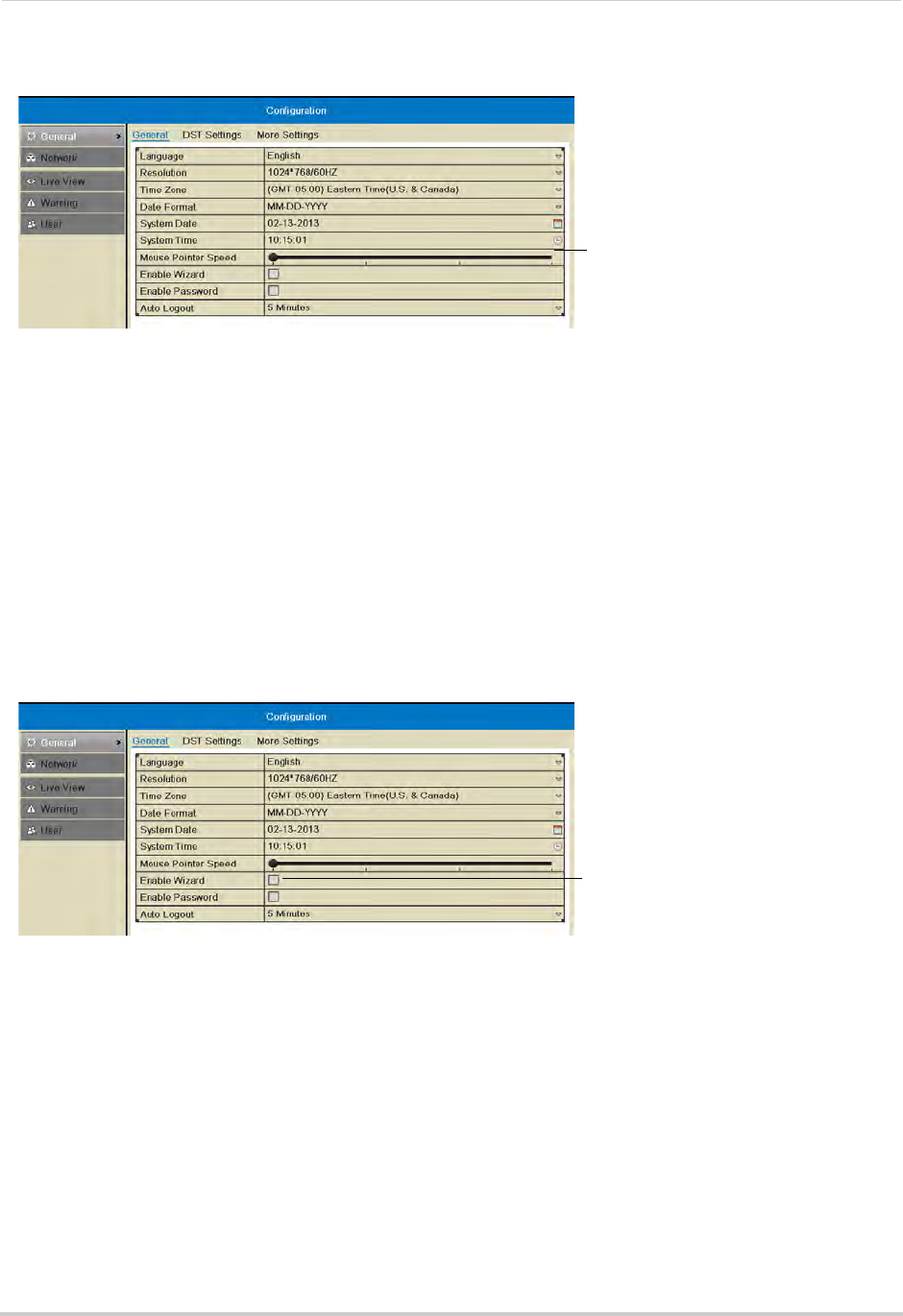
67
Configuration
2Use the Mouse Pointer Speed slider to adjust how fast the mouse moves on screen.
Select the mouse cursor speed
3Click Apply to save changes. Right-click repeatedly to return to live view.
Enabling the Start Up Wizard
The Start Up Wizard is an optional wizard that helps you set up system settings when the
NVR powers on.
To enable the Start Up Wizard:
1Right-click and click Menu.
2Enter the system user name (default: admin) and password (default: 000000) and click Yes.
3Click Configuration.
4Check Enable Wizard to enable the Start Up Wizard when the NVR powers on or un-check to
disable.
Check to enable the Start-up wizard
5Click Apply to save changes. Right-click repeatedly to return to live view. When the NVR
starts up, the Start Up Wizard guides you through setting up key system settings.
Configuring the Auto Logout Time
The Auto Logout time determines how long menus will remain open while the system is
idle.
If passwords are enabled, the user will also be logged out if the system is idle for the Auto
Logout time.
To configure the Auto Logout Time:
1Right-click and click Menu.
2Enter the system user name (default: admin) and password (default: 000000) and click Yes.
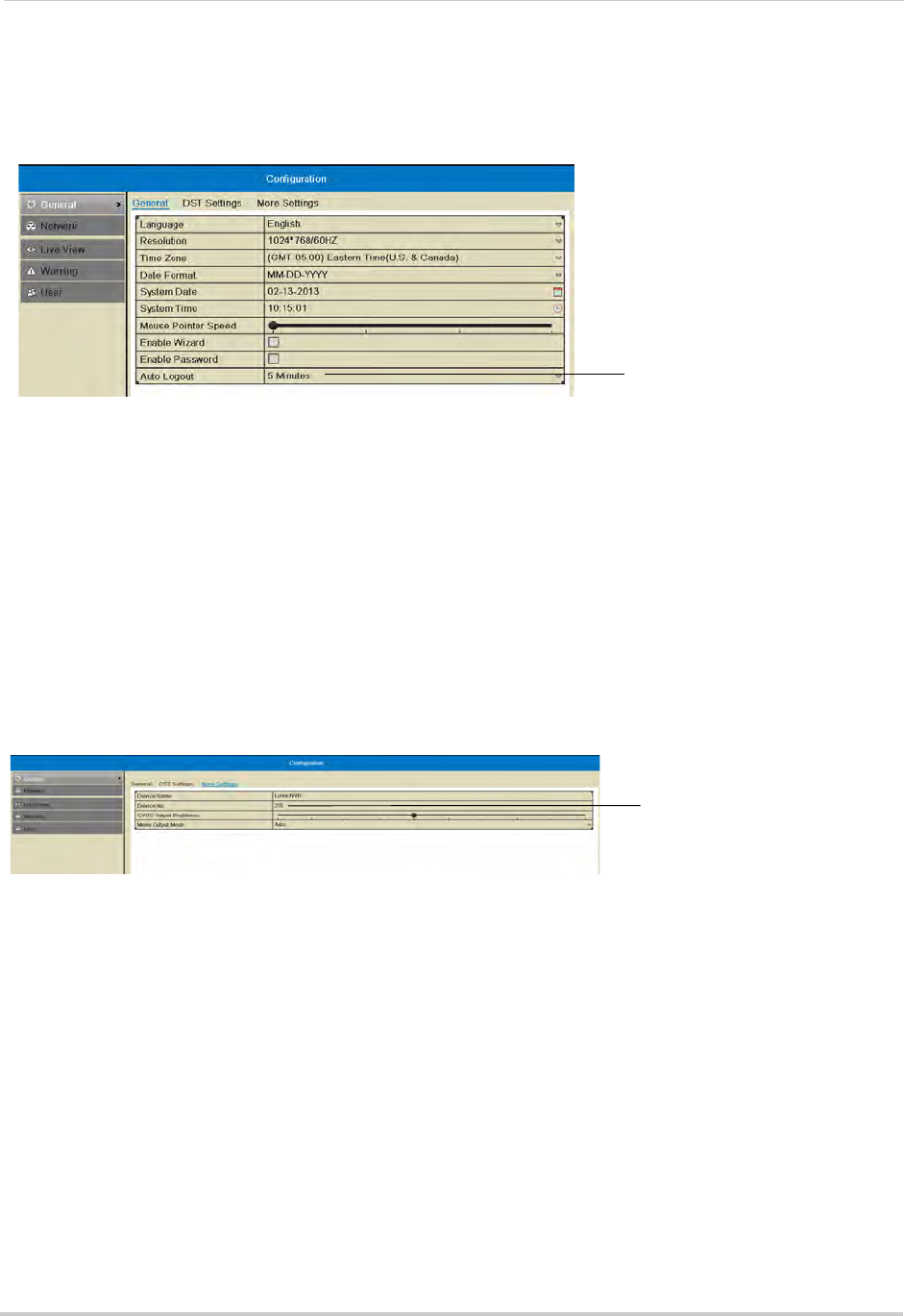
68
Configuration
3Click Configuration.
4Under Auto Logout, select the amount of time menus will remain open while the system is
idle or select Never to disable auto logout.
Select the Auto Logout time
5Click Apply to save changes. Right-click repeatedly to return to live view.
Pairing the Remote Control
The remote control comes pre-paired to your NVR. If you have more than one NVR, you can
pair the remote control to a specific NVR.
To pair the remote control to an NVR:
1Right-click and then click Menu.
2Enter the system user name (default: admin) and password (default: 000000) and click Yes.
3Click Configuration>General>More Settings.
4Click Device No. and then enter a unique ID for your NVR.
Enter a unique ID
number for you NVR
5Click Apply to save changes. Right-click repeatedly to return to live view.
6On the remote control, press DEV. Then, press the number you selected in step 3 and press
Enter. Your remote control will now be paired with the NVR.
Adjusting BNC Video Out Brightness (16-Channel Only)
On the 16-channel model, you can adjust the brightness for a monitor connected to the
Video Out (BNC) port.
To adjust the video out brightness for the BNC monitor:
1Right-click and then click Menu.
2Enter the system user name (default: admin) and password (default: 000000) and click Yes.
3Click Configuration>General>More Settings.
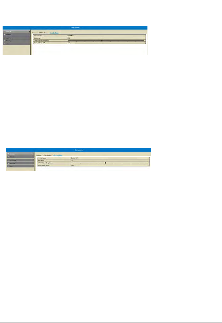
69
Configuration
4
Click to adjust the brightness
for the BNC monitor
Click inside CVBS Output Brightness to adjust the brightness of the BNC monitor.
5Click Apply to save changes. Right-click repeatedly to return to live view.
Changing the Device Name
The Device Name is the name of the system that appears in the System Information page.
You may create a custom Device Name of your choice.
To change the Device Name:
1Right-click and then click Menu.
2Enter the system user name (default: admin) and password (default: 000000) and click Yes.
3Click Configuration>More Settings.
4Under Device Name, enter a name for your NVR. This can be anything of your choice (e.g.
home, office, etc.).
Enter a name for your NVR
5Click Apply to save changes. Right-click repeatedly to return to live view.
Network
Selecting Fixed IP or DHCP
The system is capable of operating in DHCP or fixed IP address modes.
To setup a fixed IP address or DHCP:
1Right-click and then click Menu.
2Enter the system user name (default: admin) and password (default: 000000) and click Yes.
3Click Configuration>Network.
4Check Enable DHCP to have the system automatically obtain an IP address from the router.
Un-check Enable DHCP to assign a fixed IP address.
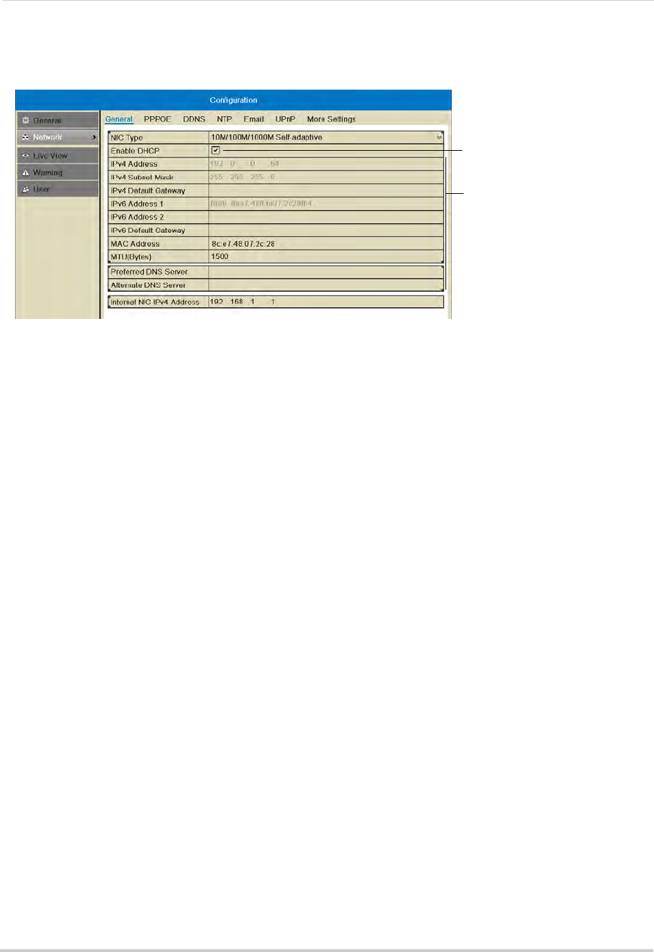
70
Configuration
• If you un-check Enable DHCP, configure the IPv4 Address, IPv4 Subnet Mask, IPv4 Default
Gateway, and Preferred DNS Server, and Alternate DNS Server.
Check to enable DHCP; un-check
to use a fixed IP address
Configure network parameters
5Click Apply to save changes. The IP address information will be updated immediately.
Right-click repeatedly to return to live view.
NOTE: If you have completed router port forwarding, you will need to re-configure your router
to forward the newly selected IP address.
Configuring Email Alerts
You can configure the NVR to send you email alerts when an event occurs (for example,
motion detection or video loss).
To configure email alerts:
1Right-click and then click Menu.
2Enter the system user name (default: admin) and password (default: 000000) and click Yes.
3Click Configuration>Network>Email.
4Configure the following:
• Email: Select Default (recommended) to use Lorex’s default email server.
OR (Advanced): Select Enable to use a custom email server. Configure the SMTP Server
address, SMTP Port, and Enable SSL according to the server’s settings.
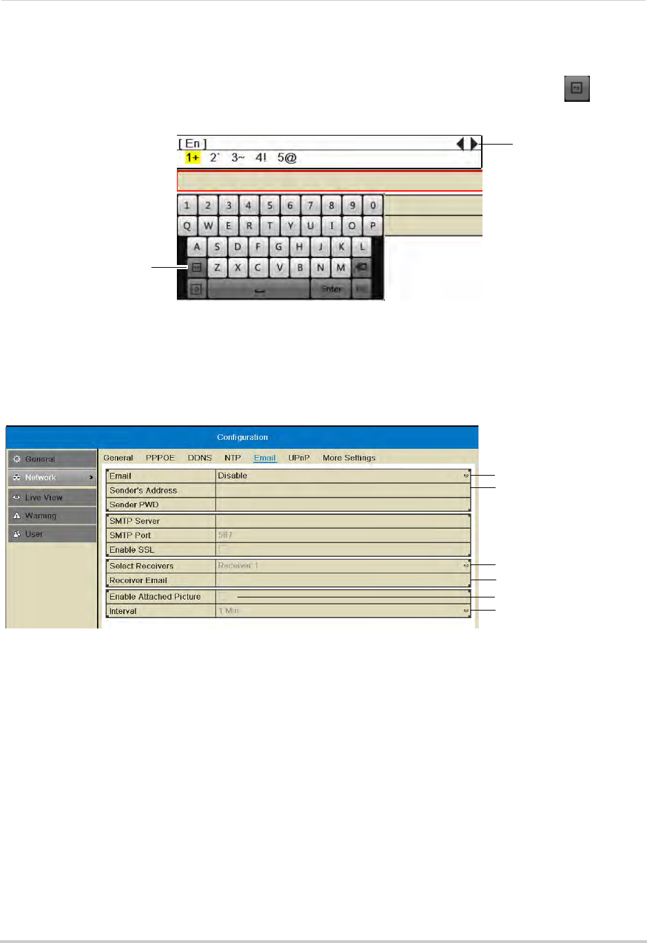
71
Configuration
• Sender’s Address: Enter the sender’s email address.
NOTE: To enter ’@’ or other special characters using the on-screen keyboard, click to bring
up special characters. Click characters to input and click the arrows to view other
characters.
Click to open special
character selector
Click to view other
special characters
• Receiver Email: Enter the email address that will receive alerts.
• Select Receivers: Use to enter additional email addresses that will receive alerts. Alerts may
be sent to up to 3 addresses.
• Enable Attached Picture: Check to include an image attachment from the camera that
triggered the alert.
• Interval: Select the interval the NVR will wait between sending out emails when events occur.
Select Default
Enter sender’s address
Enter additional
receivers
Enter receiver’s address
Enable picture attachment
Select Interval
5Click Apply to save your settings. Click Test to send a test email.
NOTE: Before the NVR will send out email alerts for motion detection, you must enable the
Send Email action for each camera. See “Configuring Motion Detection Alarm Settings”
on page 59.
Configuring DDNS Settings
Lorex DDNS is available as an optional connectivity option. Please see “Appendix C: DDNS
Setup (Advanced)” on page 160 for details.
The primary connectivity option uses the Lorex Stratus service to connect to your system
over the Internet without requiring port forwarding or DDNS registration. For details, see
“Connecting to Your NVR Over the Internet on PC or Mac” on page 83.
To configure DDNS settings:
1Right-click and then click Menu.
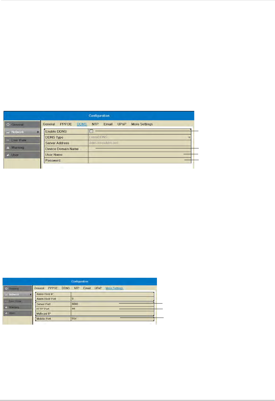
72
Configuration
2Enter the system user name (default: admin) and password (default: 000000) and click Yes.
3Click Configuration>Network>DDNS.
4Check Enable DDNS.
5Configure the following:
• DDNS Type: Select LorexDDNS.
• Device Domain Name: Enter the Domain Name/URL Request you received in the confirmation
email after you set up your DDNS account.
• User Name: Enter the DDNS User Name from the confirmation email.
• Password: Enter the DDNS Device Password from the confirmation email.
Check to enable DDNS
Enter Domain Name/URL
Request
Enter DDNS User Name
Enter DDNS Device Password
6Click Apply to save changes. Right-click repeatedly to return to live view.
Changing System Ports
The NVR’s default Client Port is 8000, the default HTTP Port is 80, and the default Mobile
Port is 1025.
To change system ports:
1Right-click and then click Menu.
2Enter the system user name (default: admin) and password (default: 000000) and click Yes.
3Click Configuration>Network>More Settings.
4Configure the Server Port, HTTP Port, and Mobile Port as needed.
Enter Server port
Enter HTTP port
Enter Mobile port
5Click Apply to save changes. Right-click repeatedly to return to live view.
NOTE: If you have completed router port forwarding, you will need to re-configure your router
to forward the newly selected ports.
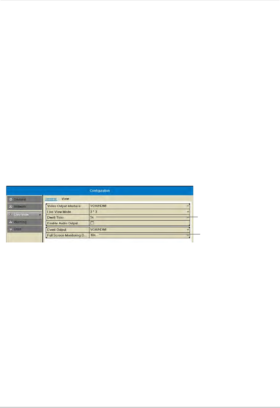
73
Configuration
Live View
Configuring Dwell Times
The Dwell Time refers to the amount of time channels or screens are shown before
switching when Sequence Mode is activated.
The Full Screen Monitoring Dwell Time refers to the amount of time channels are shown
in full screen after alarms occur, if Full Screen Monitoring is enabled.
To configure Dwell Times:
1Right-click and then click Menu.
2Enter the system user name (default: admin) and password (default: 000000) and click Yes.
3Click Configuration>Live View.
4Under Dwell Time, select the amount of time channels or screens are shown in Sequence
mode before switching.
NOTE: If you select No Switch, you will not be able to activate Sequence mode.
5Under Full Screen Monitoring Dwell Time, select the amount of time channels are shown in
full screen after alarms occur.
Select the Dwell time
Select the full-screen pop up
time
NOTE: Alarms must be enabled with full screen monitoring must be enabled before cameras
will be shown in full screen. If alarms occur simultaneously on multiple channels, each
channel will be shown in full-screen for this long before switching to the next channel.
6Click Apply to save your settings. Right-click repeatedly to return to live view.
Configuring the Layout of Channels
You can customize where channels will appear on screen.
To configure the layout of channels:
1Right-click and then click Menu.
2Enter the system user name (default: admin) and password (default: 000000) and click Yes.
3Click Configuration>Live View>View.
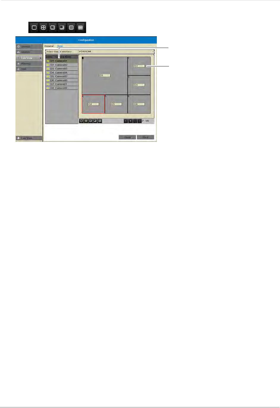
74
Configuration
4Click to select a different split-screen configuration.
Click to select an area of the screen
Double-click to display a camera in
the selected screen area
5Click inside the boxes to select an area of the screen. Double-click a camera to display it in
the selected box. This camera will replace the camera previously shown in this area.
NOTE: You can not display a camera more than once on the screen.
6Click to select different pages.
7Click Apply to save changes. Right-click repeatedly to return to live view. When you select this
split-screen configuration, the channels will be shown according to your arrangement.
Warning
Configuring System Warnings
You can configure the types of actions the system will take when errors occur.
To configure system warnings:
1Right-click and then click Menu.
2Enter the system user name (default: admin) and password (default: 000000) and click Yes.
3Click Configuration>Warning.
4Under Warning type, select All to configure all warnings, or select one of the following types
to configure:
• HDD Full: The hard drive is full.
• Hard Drive Error: Error encountered while writing to the hard drive or hard drive not
formatted.
• Network Disconnected: NVR disconnected from network.
• IP Conflicted: IP address of camera or NVR duplicated.
• Illegal Login: Wrong user name or password entered.
• Record Exception: No space for saving recorded files.
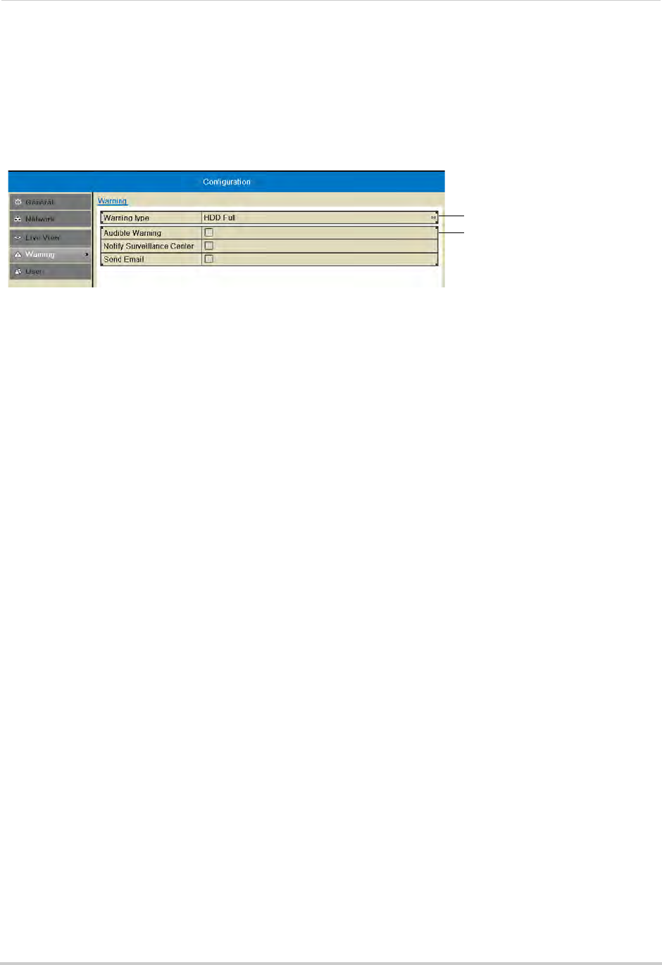
75
Configuration
5Check the warning actions you would like the system to take when the condition for the
selected warning type occurs.
• Audible Warning: The system buzzer will beep.
• Notify Surveillance Center: A warning is sent to the client software.
• Send Email: An alert email is sent. Note that email alerts must be enabled before emails are
sent. For details on enabling email alerts, see “Configuring Email Alerts” on page 70.
Select warning type
Select warning actions
6Click Apply to save changes. Right-click repeatedly to exit all menus.
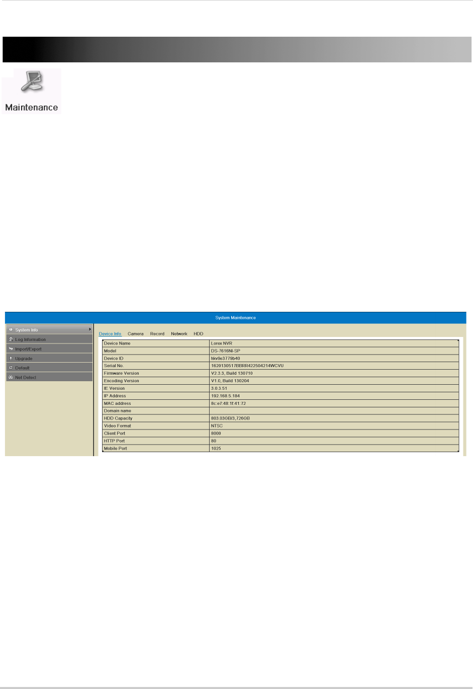
76
Maintenance
Maintenance
View system info and device logs. Update firmware, reset to factory default
settings, and import/export system configuration.
The Maintenance Menu contains the following sub-menus:
• System Info
• Log Information
• Import/Export
• Upgrade
• Default
• Net Detect
System Info
Viewing System Info
The System Info sub-menu shows detailed information about the system.
To view detailed system information:
1Right-click and click Menu>Maintenance. Click the tabs to view information on the following
system components:
• Device Info: Shows an overview of key system info, such as the Device ID, IP address, MAC
address, firmware version, and system ports.
• Camera: Shows information about connected cameras.
• Record: Shows the recording settings that are currently in use.
• Network: Shows detailed network information.
• HDD: Shows information about hard drives connected to the system.
Log Information
Searching for System Logs
System logs are recorded when events occur on the system. Logged events include
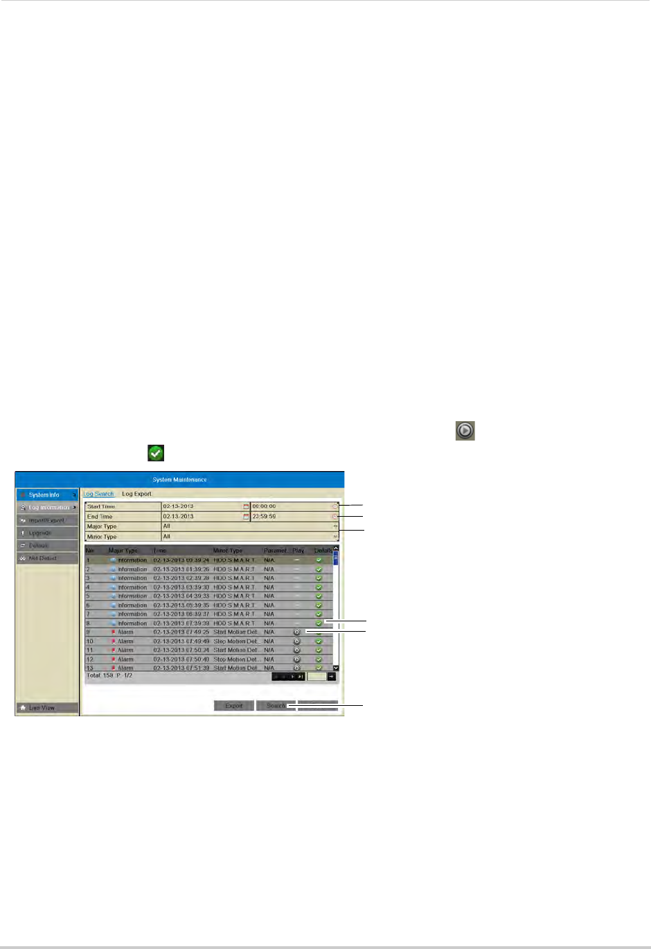
77
Maintenance
alarms, configuration changes, maintenance actions (such as the system powering on or
off), and warnings (such as network or camera disconnection).
To search for system logs:
1Right-click and then click Menu.
2Enter the system user name (default: admin) and password (default: 000000) and click Yes.
3Click Maintenance>Log Information.
4Under Start Time and End Time, select the start time and end time for your log search.
5Under Major Type, select All to search for all system logs, or select a type of log to search
for:
• Alarm: System alarms, such as motion detection and tamper-proof alarms.
• Warning: System warnings, such as a camera disconnection or hard drive errors.
• Operation: System operations, such as configuration changes.
• Information: System information logs.
6Under Minor Type, select All to search for all system logs in the Major Type you have selected
or select a specific type of log to search for.
7Click Search to view a list of logs that match your criteria. Click to playback video related
to the log or click to see details for the log entry.
Select start time for your search
Select end time for your search
Select log type to search for
View log details
Playback video from log time
Click to search
Exporting System Logs to USB
You can export system logs to the USB flash drive (not included) or external hard drive (not
included).
To export system logs:
1Connect a USB flash drive (not included) or external hard drive (not included) into one of the
USB ports on the system.
2Perform a log search using the instructions in “Searching for System Logs” on page 76.
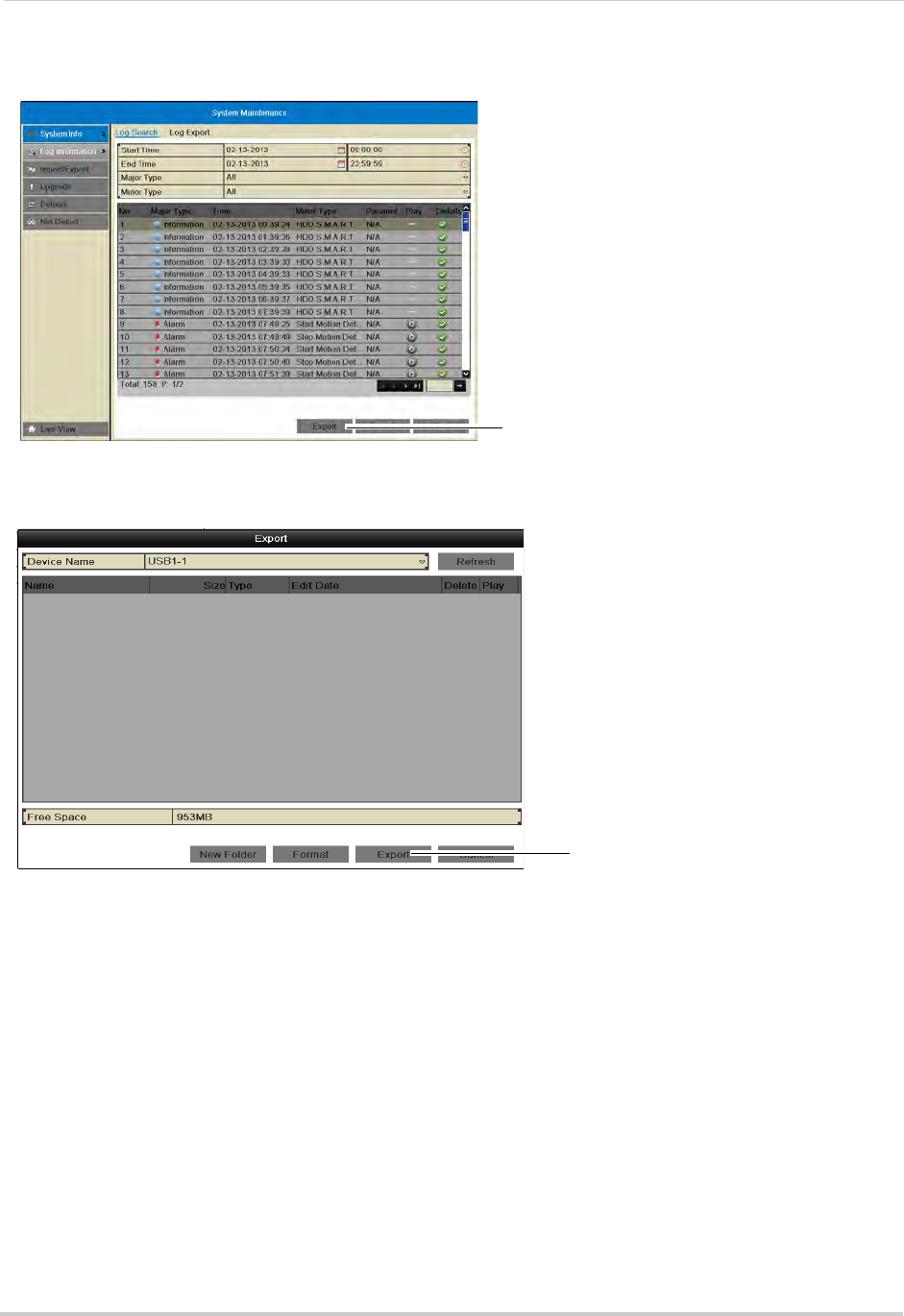
78
Maintenance
3Click Export.
Click to export logs
4Click Export again to export the list of system logs. Wait for the export to complete before
disconnecting your USB flash drive or external hard drive.
Click Export
Import/Export
Saving Your System Configuration to USB
You can save your current system configuration to a USB flash drive (not included). This is
useful if you want to backup your current settings.
NOTE: This function only saves settings created in system menus. It does not save or backup
any video.
To save your system configuration to a USB flash drive:
1Connect a USB flash drive (not included) or external hard drive (not included) into one of the
USB ports on the system.
2Right-click and then click Menu.
3Enter the system user name (default: admin) and password (default: 000000) and click Yes.
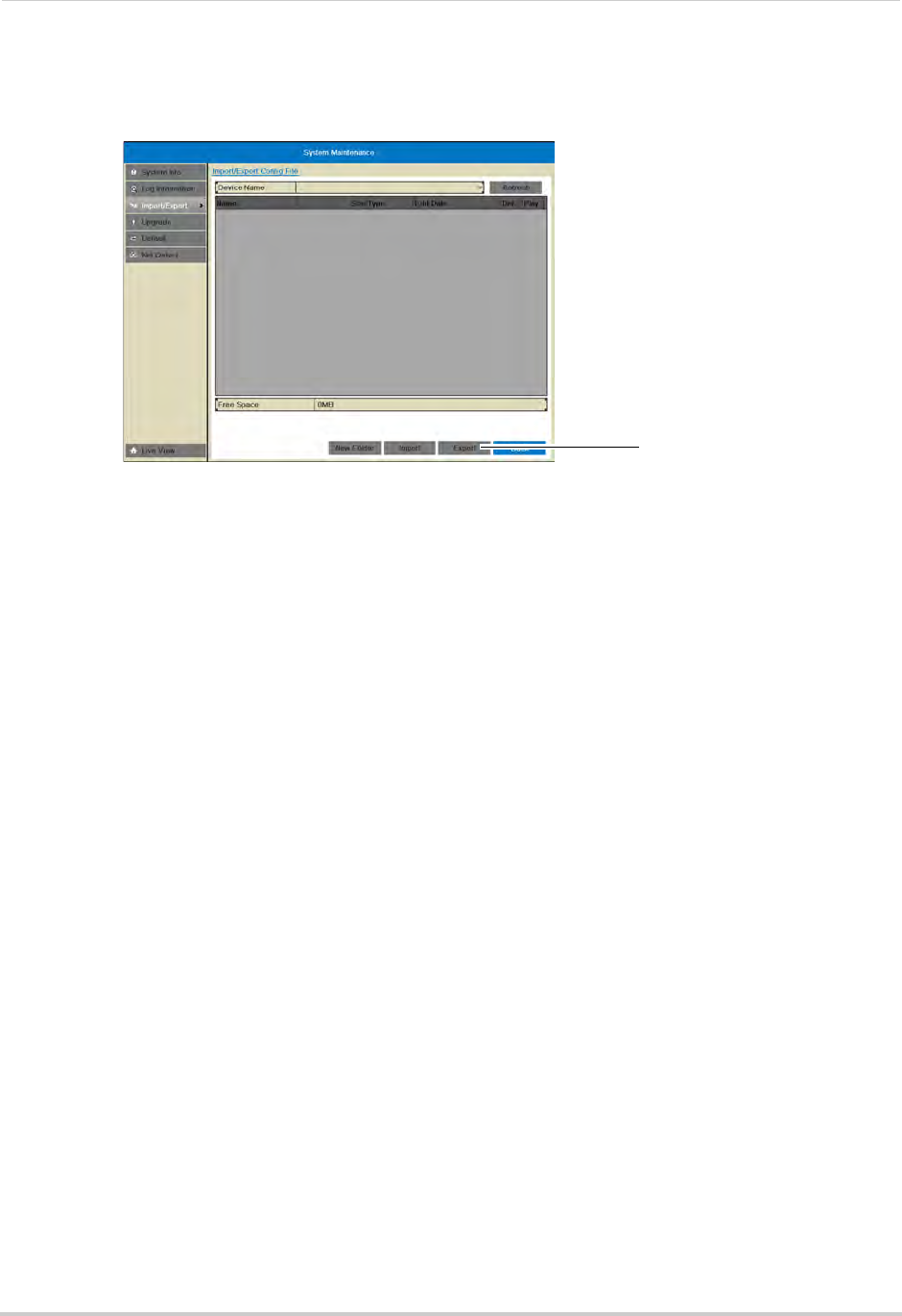
79
Maintenance
4Click Maintenance>Import/Export.
5Click Export. Wait for the export to complete.
Click Export
Loading a System Configuration from USB
1Connect a USB flash drive (not included) or external hard drive (not included) with a saved
configuration file into one of the USB ports on the system.
2Right-click and then click Menu.
3Enter the system user name (default: admin) and password (default: 000000) and click Yes.
4Click Maintenance>Import/Export.
5Click the configuration file you would like to load, and then click Import. Click Yes to confirm.
The system will reboot and then restart with the new settings.
Upgrade
Upgrading the System Firmware
Firmware upgrades can provide improved functionality to your NVR. Firmware upgrades
can provide improved functionality to your NVR. When firmware upgrades become
available, you will automatically be prompted to upgrade your system. You must have the
latest NVR firmware and client software or mobile apps to connect to the NVR over the
Internet.
You can manually check for firmware upgrades to download directly to the system from the
Internet.
If your system does not have an Internet connection, you can upgrade the firmware using
a USB thumb drive (not included). When firmware upgrades become available, you can
download them for free from www.lorextechnology.com.
To manually check for firmware upgrades:
1Right-click to open the Quick Menu and select Menu.
2Enter the system user name (default: admin) and password (default: 000000) and click Yes.
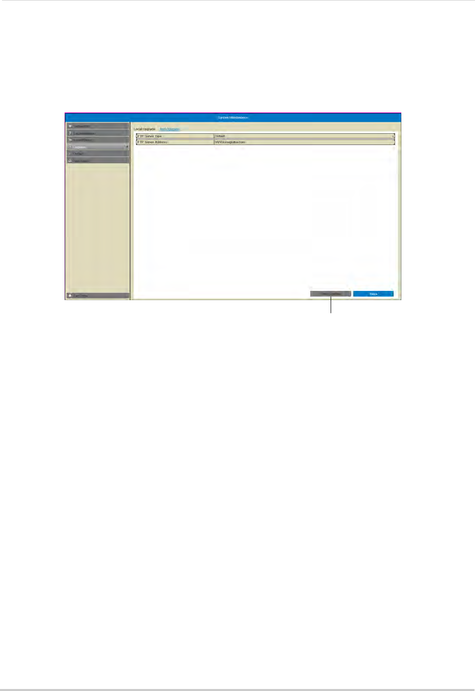
80
Maintenance
3Click Maintenance. Then, click Upgrade.
4Click the Auto Upgrade tab.
5Click Check Update. The NVR will check online for a firmware upgrade. If a firmware upgrade
is found, click Yes to upgrade the firmware.
Click Check Update
6Wait for the firmware upgrade to complete. Do not disconnect the power or remove the USB
flash drive during the firmware upgrade. The NVR will reboot once the firmware upgrade is
completed.
To upgrade firmware using a USB drive:
1In your web browser, visit www.lorextechnology.com and search for the model number of
your NVR (check the label underneath your NVR for the model number). Download the free
firmware upgrade if one is available.
2Insert a blank USB flash drive (not included) into your computer. Extract the firmware file and
copy it to the flash drive.
3Insert the USB flash drive in one of the USB ports on the front or rear panel of the NVR.
4Right-click to open the Quick Menu and select Menu.
5Enter the system user name (default: admin) and password (default: 000000) and click Yes.
6Click Maintenance. Then, click Upgrade.
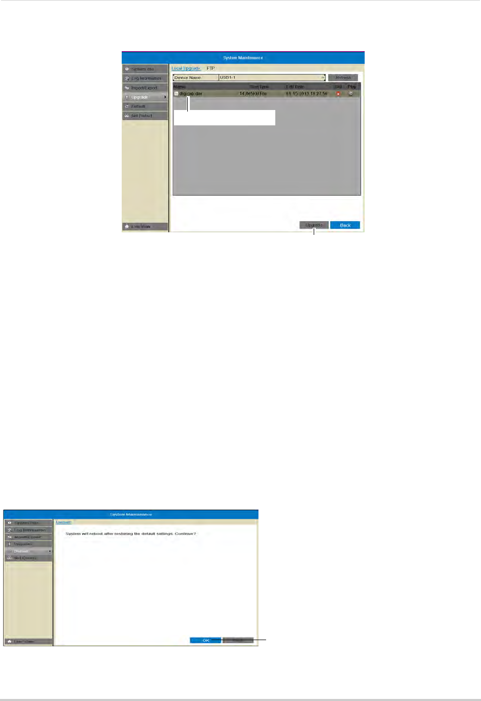
81
Maintenance
7Click on the firmware file and click Upgrade.
Click the firmware file
Click Upgrade
8Click Yes to confirm.
9Wait for the firmware upgrade to complete. Do not disconnect the power or remove the USB
flash drive during the firmware upgrade. The NVR will reboot once the firmware upgrade is
completed.
Default
Resetting the System to Factory Default Settings
Restoring to factory default settings reverts any setting changes you have made to their
original settings. This does not affect the recordings saved on the NVR.
To reset to factory default settings:
1Right-click and then click Menu.
2Enter the system user name (default: admin) and password (default: 000000) and click Yes.
3Click Default then click OK. The system will reboot and then restart with the factory default
settings.
Click Ok to reset the NVR to factory default settings
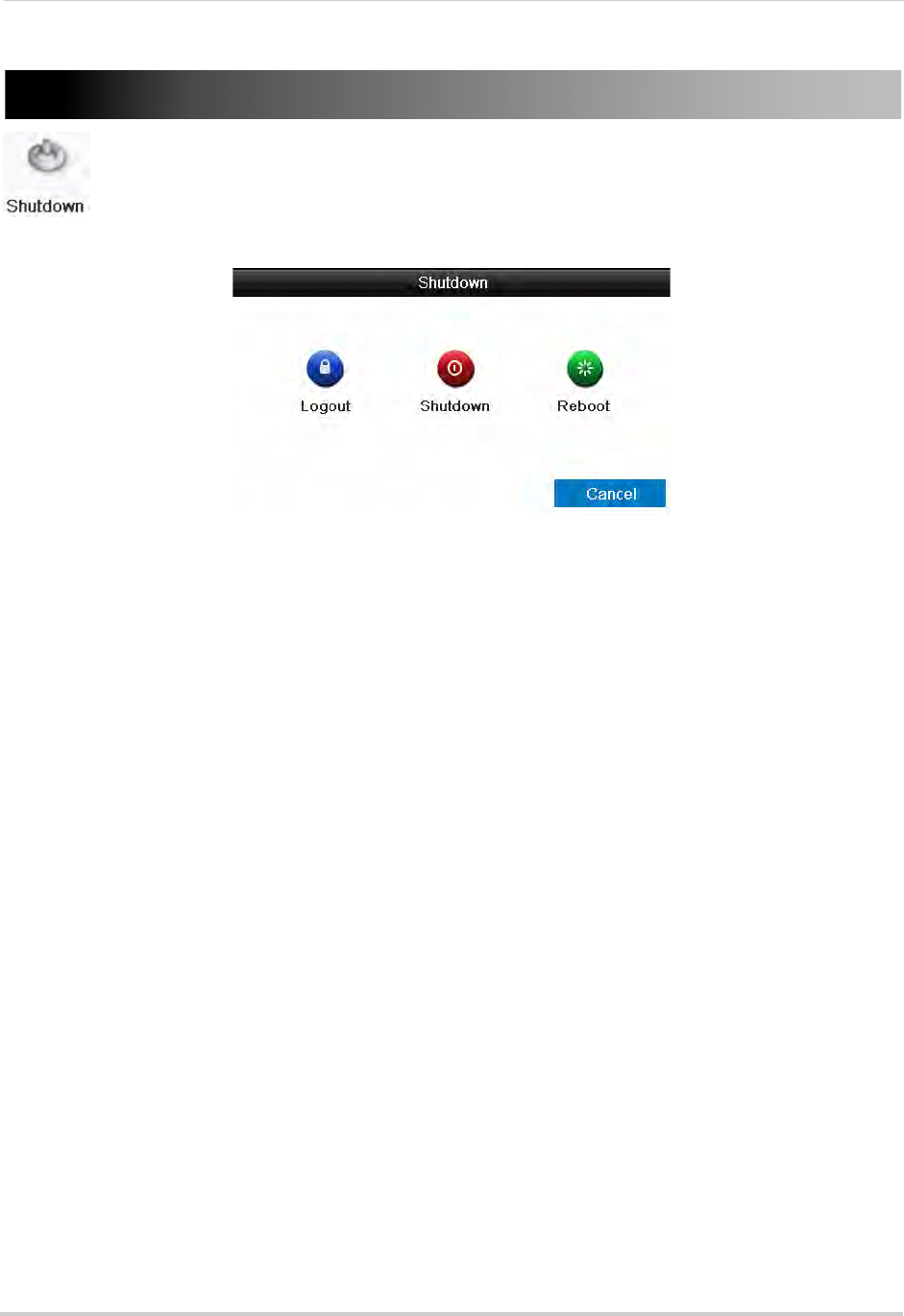
82
Shutdown
Shutdown
The Shutdown menu allows you to log out, shutdown, or reboot the system.
The Shutdown menu has the following options:
• Logout: Click to log out the current active user.
NOTE: If passwords are not activated on the system, clicking Logout will log out the admin
account. You will need to enter the admin password (default: 000000) to re-enter the
menu.
• Shutdown: Click to shut down the system. The admin password (default: 000000) is required.
After shutdown is complete, turn the power switch to off to power off the NVR.
• Reboot: Click to restart the NVR.
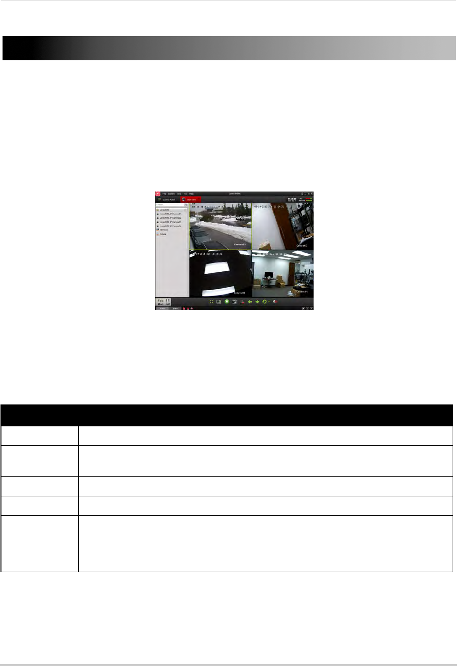
83
Connecting to Your NVR Over the Internet on PC or Mac
Connecting to Your NVR Over the Internet on PC
or Mac
This NVR features connectivity using the exclusive Lorex Stratus solution. This
cloud-enabled service allows for Internet connectivity without requiring any network
configuration. Up to 3 devices may connect to the system at the same time.
This section refers to Internet setup on PC or Mac, for smartphone/tablet setup, see
“Mobile Apps: Accessing your NVR Using a Mobile Device” on page 132.
Client Software for PC/Mac
For details on navigating the client software, see “Client Software for PC or Mac” on
System Requirements
Prior to using Lorex Client Software, make sure your system meets or exceeds the
following system requirements:
Description Requirement
CPU Core 2 Duo 3.0GHz
Operating
System
Windows™ 8/7/Vista
Memory 2GB
Video 512 MB of video memory and above
Network (LAN) 10/100 BaseT Network
Network (WAN) 1 Mbps upstream
High-speed Internet service is required to remotely connect to your system.
NOTE: If a user connects to the system remotely, there may be slow performance when
accessing the system locally. This is normal, and not a malfunction.
For the latest compatibility list, check www.lorextechnology.com, as new software versions are released to
the market.
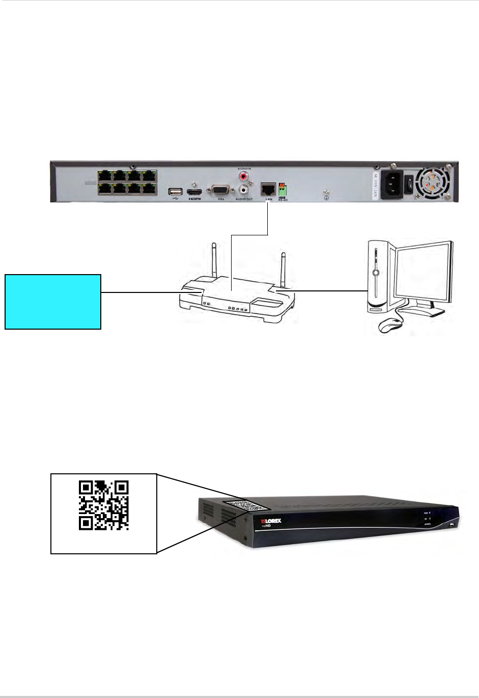
84
Connecting to Your NVR Over the Internet on PC or Mac
Step 1 of 3 Connect your NVR to your Router
1Power off your NVR by turning the power switch to .
2Connect an Ethernet cable (included) to the LAN port on the rear panel of the NVR. Connect
the other end of the Ethernet cable to an empty LAN port (usually numbered 1~4) on your
router.
3Turn the power switch to I to power the NVR back on.
ROUTER
(Not Included)
COMPUTER
(Not Included)
(not required for
local viewing)
INTERNET
Ethernet Cable (included)
8-channel model shown
Step 2 of 3: Obtain the NVR’s Device ID
The Device ID is a unique code that allows your system to handshake with the Lorex servers
for connection over the Internet.
To find the Device ID:
1Locate the QR code label on the top of the NVR.
Device ID: xxxxxxxxx
2Write down the Device ID.
Step 3 of 3: Connect to the NVR over the Internet
Follow the steps below to connect to your NVR over the Internet on PC or Mac.
NOTE:
Make sure to upgrade your NVR firmware and client software to the latest version.
You
must have the latest NVR firmware and client software to connect to the NVR over the
Internet.
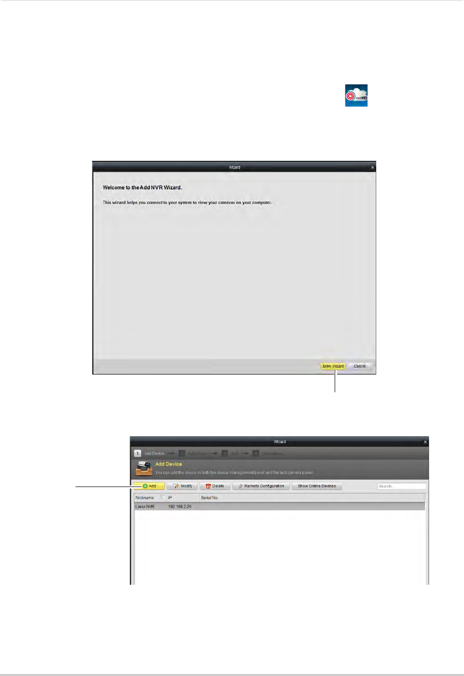
85
Connecting to Your NVR Over the Internet on PC or Mac
To connect to the NVR over the Internet:
1Install the Client Software for PC or the Client Software for Mac from the CD or download
the client software for free from www.lorextechnology.com.
2Double-click the Lorex netHD Stratus Client icon from the desktop ( ). The client
software opens to the Add NVR Wizard.
NOTE: If the Add NVR Wizard doesn’t open, click Help>Open Wizard.
3
Click Enter Wizard
Click Enter Wizard.
4Click Add.
Click Add
5Under Name, enter a name for your NVR of your choice (e.g. home or office).
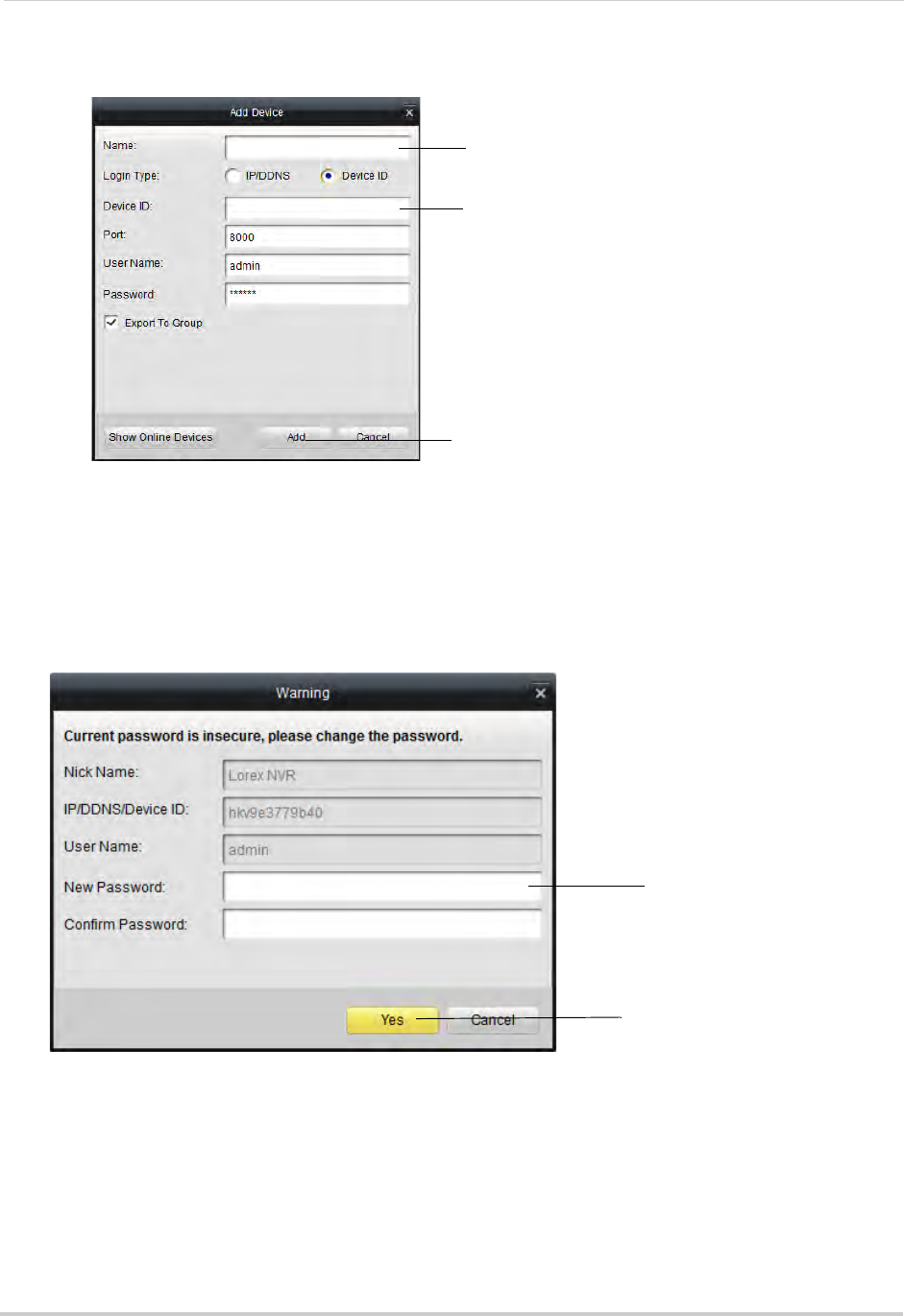
86
Connecting to Your NVR Over the Internet on PC or Mac
6Under Device ID, enter the Device ID printed on the top panel of your NVR.
Click Add
Enter a name for your NVR
Enter the Device ID
NOTE: If you have changed the Client Port, User Name, or Password from the defaults, you
must update them to connect to the NVR.
7Click Add.
8If this is the first time connecting to the system, you will be prompted to change the
password. Enter a new 6 character password and click Yes. This password will be used to
connect to your system from now on.
Enter a new password
Enter a new password
9Click Next 3 times, then click Finished.
10 The NVR opens in Main View and streams video from your cameras.
NOTE: If Main View does not open, click Control Panel>Main View to open the Main View menu.
Then drag the NVR folder to the display area.
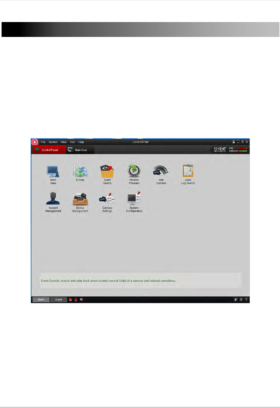
87
Client Software for PC or Mac
Client Software for PC or Mac
Lorex netHD Stratus Client allows you to connect to multiple NVRs and view up to 64 IP
cameras on one screen.
NOTE: For details on connecting to your NVR over a local area network (LAN) or the Internet,
see “Connecting to Your NVR Over the Internet on PC or Mac” on page 83.
Control Panel
You can access your NVRs, including live and recorded video and configuration through the
Control Panel. You may return to the Control Panel at any time by clicking the Control
Panel tab.
The menus available through the Control Panel are:
• Main View: View live video from your IP cameras. For details, see “Main View” on page 88.
• E-Map: E-Map allows you to visualize the position of your cameras against an image, such
as a map or floor plan. For details, see “E-Map” on page 96.
• Event Search: Search for events on your NVRs. For details, see “Event Search” on page 98.
• Remote Playback: Playback recorded video from your NVR. For details, see “Remote
Playback” on page 101.
• Add Camera: Manage camera groups. For details, see “Add Camera” on page 105.
• Local Log Search: Search for logs on your NVRs. For details, see “Local Log Search” on
page 106.
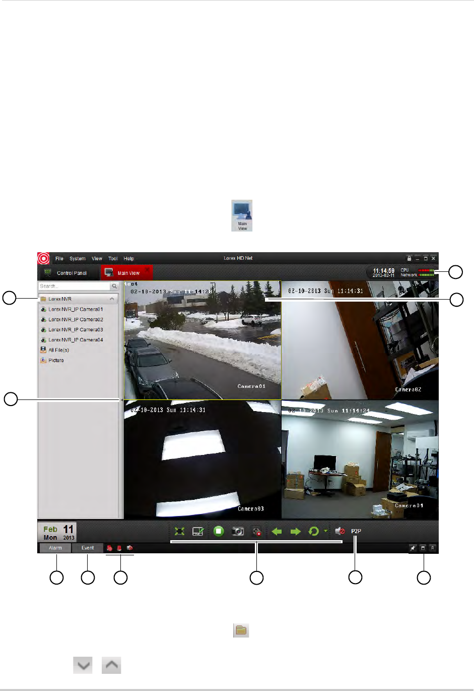
88
Client Software for PC or Mac
• Account Management: Configure user accounts and passwords for the client software. For
details, see “Account Management” on page 107.
• Device Management: Add or remove NVRs from the client software. Remotely configure your
NVRs. For details, see “Device Management” on page 109.
• Camera Settings: Configure camera settings. For details, see “Camera Settings” on page 117.
• System Configuration: Configure client software settings. For details, see “System
Configuration” on page 129.
Main View
Main View allows you to view live video from your IP cameras.
To access Main View:
• From the Control Panel, click Main View ( )
1
2
3 4 568
9
10
7
.
1NVR/Camera List: Shows a list of all NVRs/camera groups and cameras connected to the
client software.
• NVRs or camera groups are shown with a icon.
• Double click an NVR or camera group to open all the cameras connected to it.
• Click / to expand/hide the cameras and options for the NVR or camera group.
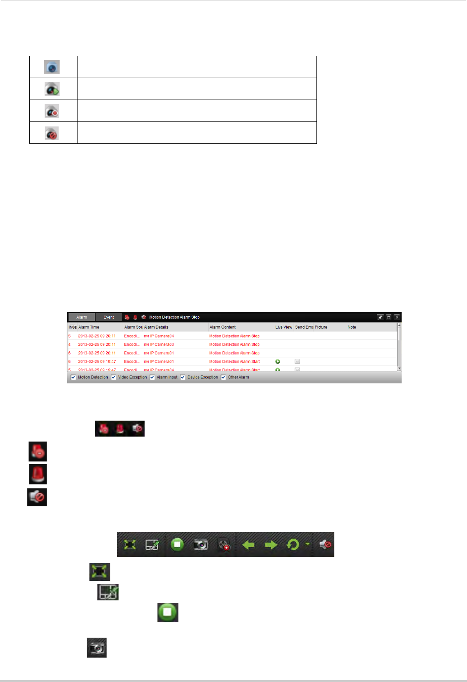
89
Client Software for PC or Mac
• Cameras are shown with one of the following icons:
Camera online, but not selected in live view.
Camera online and selected in live view.
Manual recording is currently activated.
Camera is offline (connection issue).
• Click-and-drag cameras to the display grid to open them.
• All Files: Open Manual Recordings for this NVR or camera group. See “Using All Files to View
Manual Recordings and Downloaded Video Files” on page 93.
• Picture: Open screenshots for this NVR or camera group. See “Using Pictures to View
Screenshots” on page 94.
2Hide NVR/Camera List: Click the arrow to hide/show the NVR/Camera List.
3Alarm: Click to show the Alarm Panel. The Alarm Panel shows a list of system alarms and
events, such as motion detection events. Note that you must enable Notify Surveillance
Center to Receive notifications of motion events. For details, see “Configuring Motion
Detection Alarm Settings” on page 59.
4Event: Not supported.
5Alarm Actions:
• Clear Alarms: Click to clear all alarms from the list.
• Enable Alarm Popup Window: Click to have alarms appear in a popup window.
• Enable Audio Alarms: Click to have the Client Software play an alarm sound when alarms
occur.
6Main View Toolbar:
• Full-Screen : Click to open the display grid in full-screen. Press ESC to exit full-screen.
• Select Layout : Click to select a display grid layout.
• Stop/Resume Live Display : Click to stop camera streaming on all channels. Click again
to resume camera streaming.
• Screenshot : Click to save a screenshot of the currently selected channel.
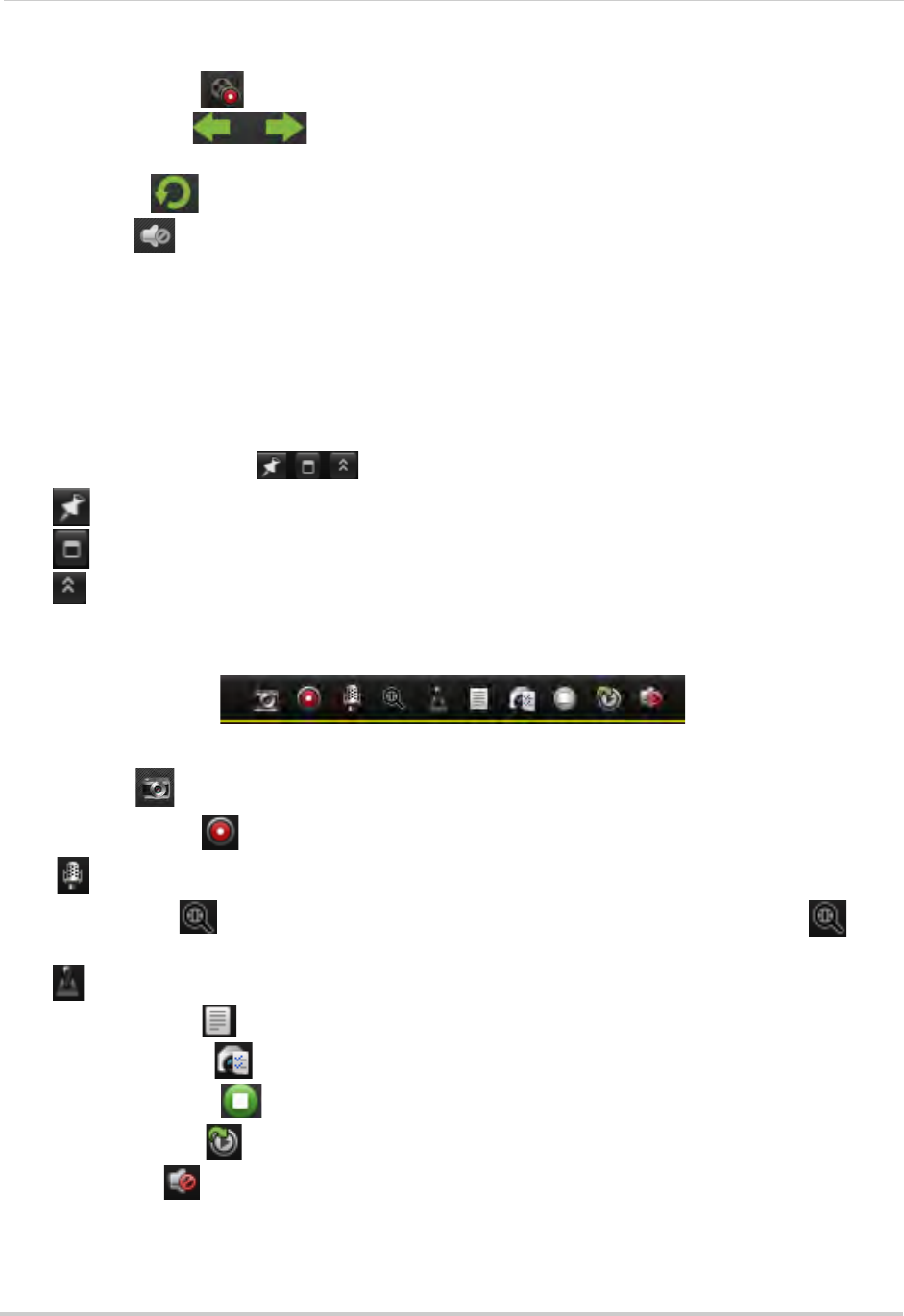
90
Client Software for PC or Mac
• Manual Record : Click to start/stop manually recording the currently selected channel.
• Previous/Next : C l i c k t o g o t o t h e p re v i o u s o r n e x t c a m e r a o r p a g e w h e n S e q u e n c e
mode is enabled.
• Sequence : Click to start/stop Sequence mode.
• Volume : Click to control volume.
7Connection Status: Shows the type of connection used.
• P2P (peer-to-peer) indicates that the video is streaming directly from the NVR to the computer
running the Client Software.
• RLY (relay) indicates that the video is streaming through a Lorex video server. While relay
mode is activated, the system will disconnect after 10 minutes of inactivity. Relay mode is only
used when a direct connection cannot be made between the NVR and computer.
8Alarm Panel Controls:
• Auto-hide: Click to enable/disable alarm panel auto-hide.
• Maximize Alarm Panel: Click to open the Alarm Panel in its own tab.
• Show/hide Alarm Panel
9Camera Display: Click to select a channel. Hold the mouse over the channel to access the
Camera Toolbar. The camera toolbar contains the following options:
Camera Toolbar
• Capture : Click to take a screenshot from the currently selected camera.
• Manual Record : Click to start/stop manual recording of the currently selected camera.
• : Not supported.
• Digital Zoom : Click to enable digital zoom mode. The cursor will change to a icon.
Then, click and drag on the camera picture to zoom in. Click again to zoom out.
• : Not supported.
• Camera Status : Show the camera status menu.
• Camera Settings : Open the Camera Settings menu. See “Camera Settings” on page 117.
• Stop Live Display : Click to stop streaming the selected camera.
• Quick Playback : Click to open Quick Playback mode.
• Mute audio : Click to mute/unmute audio from the selected camera. Audio-enabled
cameras required (not included).
10 CPU and Network Status: Shows the level of CPU and network use on your computer.
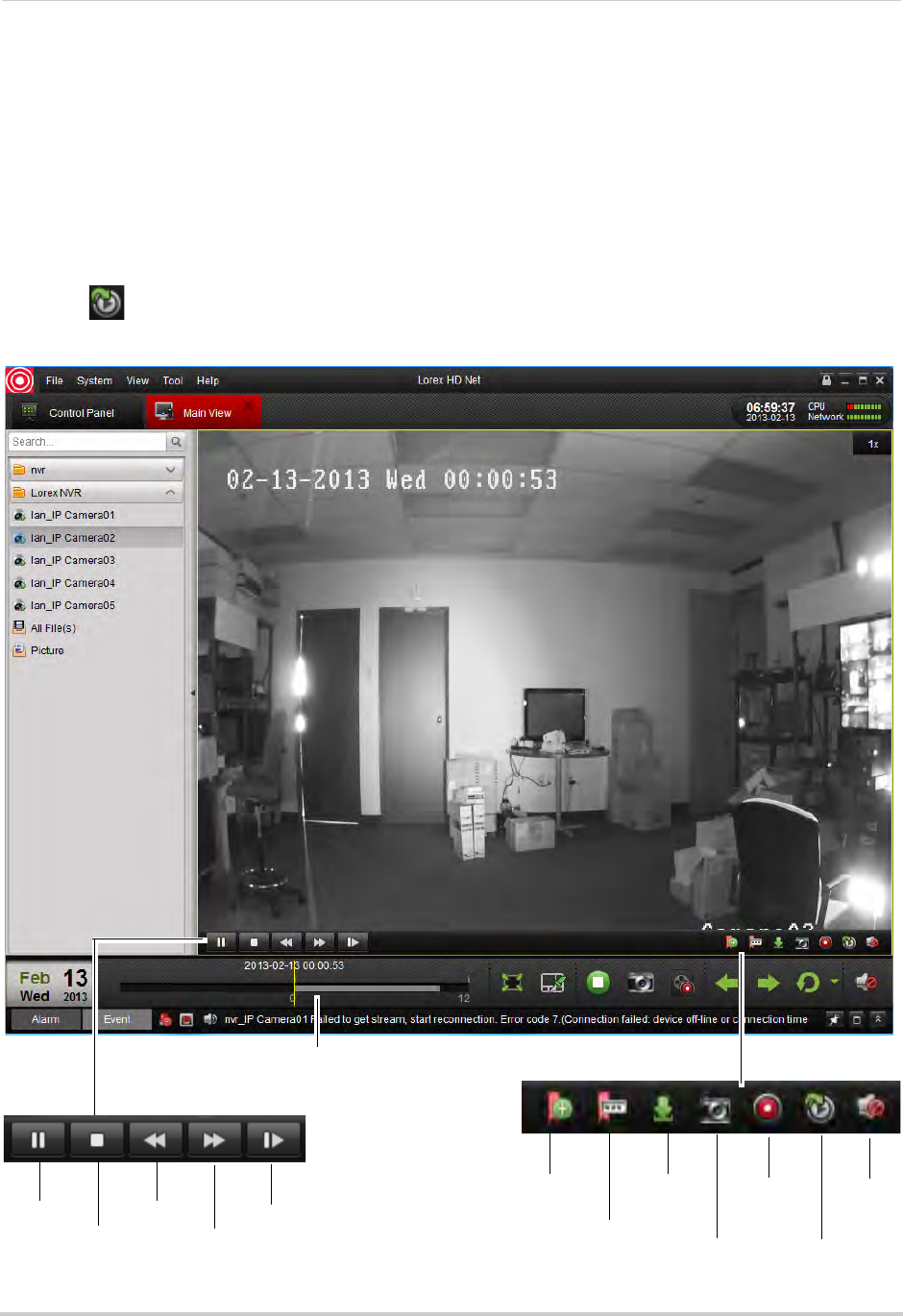
91
Client Software for PC or Mac
Using Quick Playback Mode
Quick Playback mode allows you to view recorded video from your cameras without leaving
the Main View tab. You can also view recorded video from one camera while still viewing
the rest of your cameras live.
To access Quick Playback Mode:
1Click the camera you would like to playback and hold the mouse over the camera to open the
Camera Toolbar.
2Click to open Quick Playback mode.
3Use the Quick Playback controls.
Click and drag to select
the playback time
Pause
Stop
Slow
Fast
Forward
Frame-by-frame
Add default tag
Add custom tag
Download
tag Start/stop
manual
recording
Screenshot Return to live
viewing
Mute/
unmute
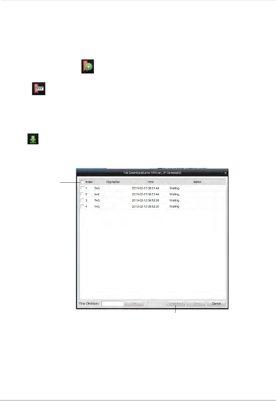
92
Client Software for PC or Mac
Tagging Video Through Quick Playback
You can add tags to video to mark key events. Tags created through Quick Playback are also
saved in the NVR, so you can search for them using the NVR menus.
To tag video through Quick Playback:
• During Playback, click to add a default tag.
OR
• Click to add a custom tag. Then, enter the tag name and click Yes to save.
Downloading Tagged Video
You can download video marked with tags to your computer’s hard drive.
To download tagged video:
1Click to open the Download Tags menu.
2Check the tags you would like to download then click Download. 1 minute video files are
downloaded for each tag.
Check tags you would
like to download
Click Download
• To view downloaded video files, click All Files in the NVR/Camera List. For details, see “Using
All Files to View Manual Recordings and Downloaded Video Files” on page 93.
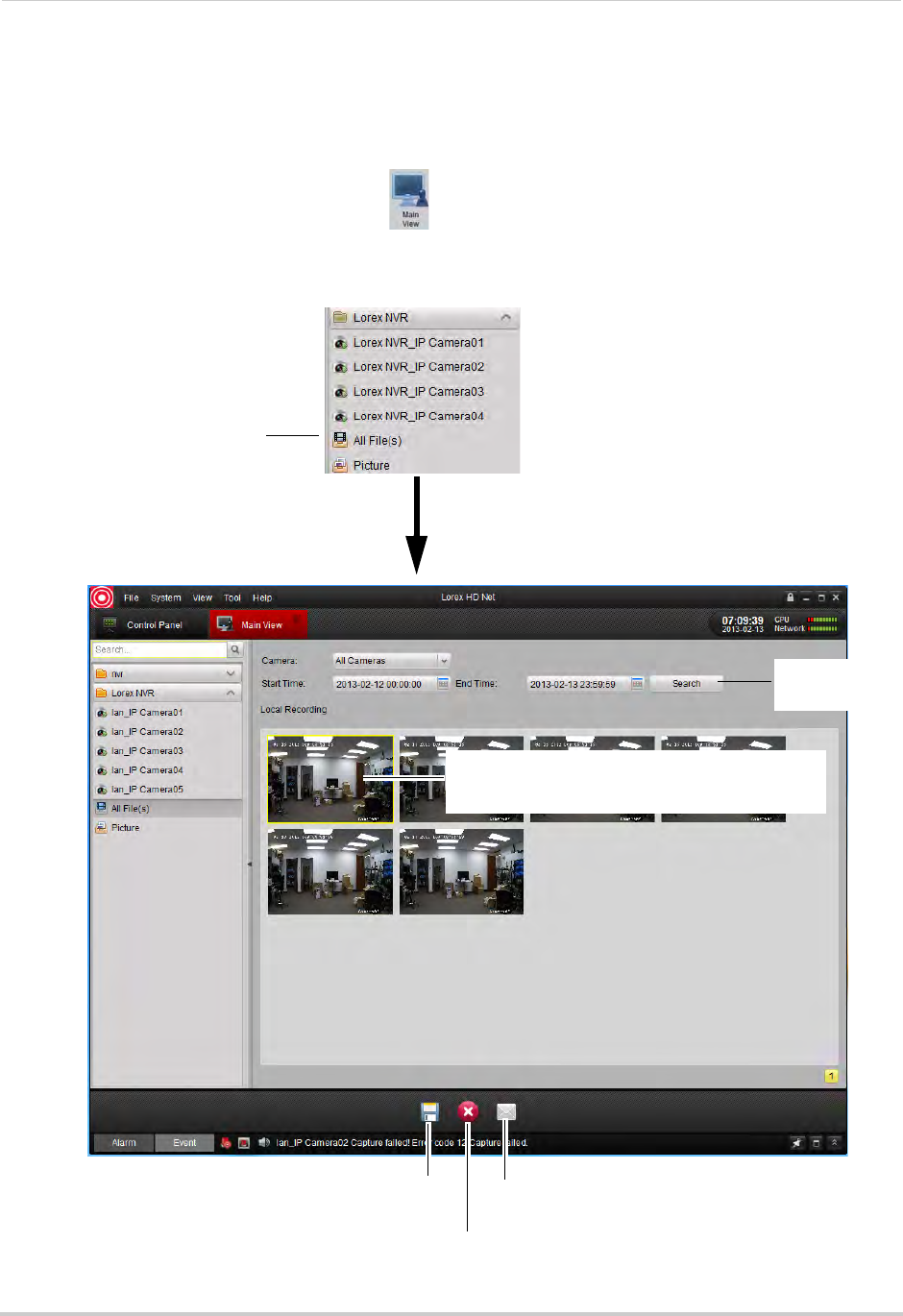
93
Client Software for PC or Mac
Using All Files to View Manual Recordings and Downloaded Video Files
Use the All Files option to access manual recordings and downloaded video files.
To use All Files to access manual recordings:
1From Control Panel, click Main View ( ).
2In the NVR/Camera List, click All Files. A list of manual recordings and downloaded video
files saved on your computer for this NVR opens.
Click All Files
Double-click to open video files in Video Player.
For details on using the Video Player, see “Video
Player Controls” on page 96.
Search for
video files
Click to Save files to
a different location
Delete file
Email file
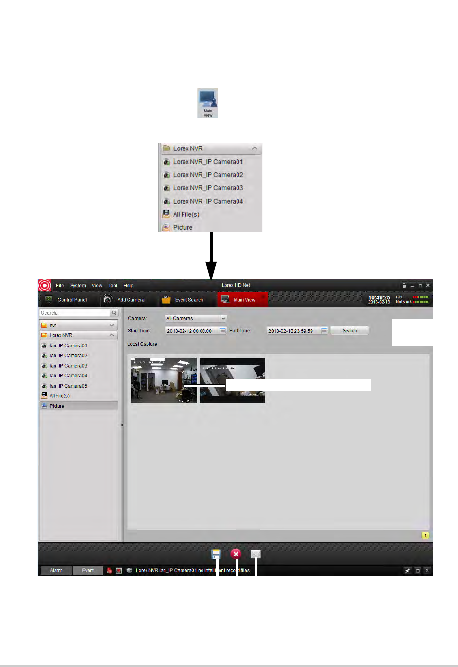
94
Client Software for PC or Mac
Using Pictures to View Screenshots
Use the Pictures option to view screenshots you have saved using the Client Software.
To access Pictures:
1From Control Panel, click Main View ( ).
2In the NVR/Camera List, click Picture. A list of screenshots for your NVR opens.
Click Picture
Double-click to open screenshots
Search for
screenshots
Click to Save files to
a different location
Delete file
Email file
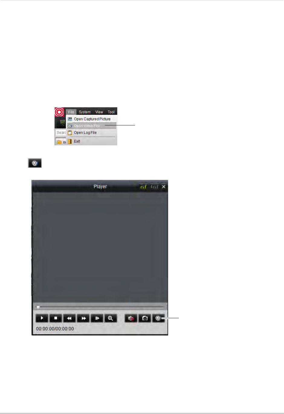
95
Client Software for PC or Mac
Video Player
The Video Player allows you to open backup video files extracted from the NVR or to play
manual recordings or downloaded video files.
Opening Backup Video Files
The client software can open backup video files extracted from the NVR. For details on
extracting video files from the NVR, see “Backing Up Video” on page 32.
To open backup video files in the Client Software:
1Click File>Open Video File. The Video Player opens.
Click File>Open Video File
2Click . Then select your video file and click Open. It will begin playing back in the Video
Player.
Click to open a video file
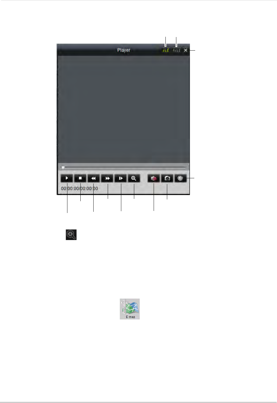
96
Client Software for PC or Mac
Video Player Controls
Pause/play
Stop
Slow
Fast
forward
Frame-by
-frame
Zoom in
Mute/unmute
Screenshot
Open file
Close
Small Player Large Player
• To zoom in, click and click-and-drag. Click again to zoom out.
E-Map
E-Map allows you to visualize the position of your cameras against an image, such as a map
or floor plan. This is useful if you need to differentiate between cameras in similar looking
areas.
To create an E-Map:
1From the Control Panel, click E-Map ( ).
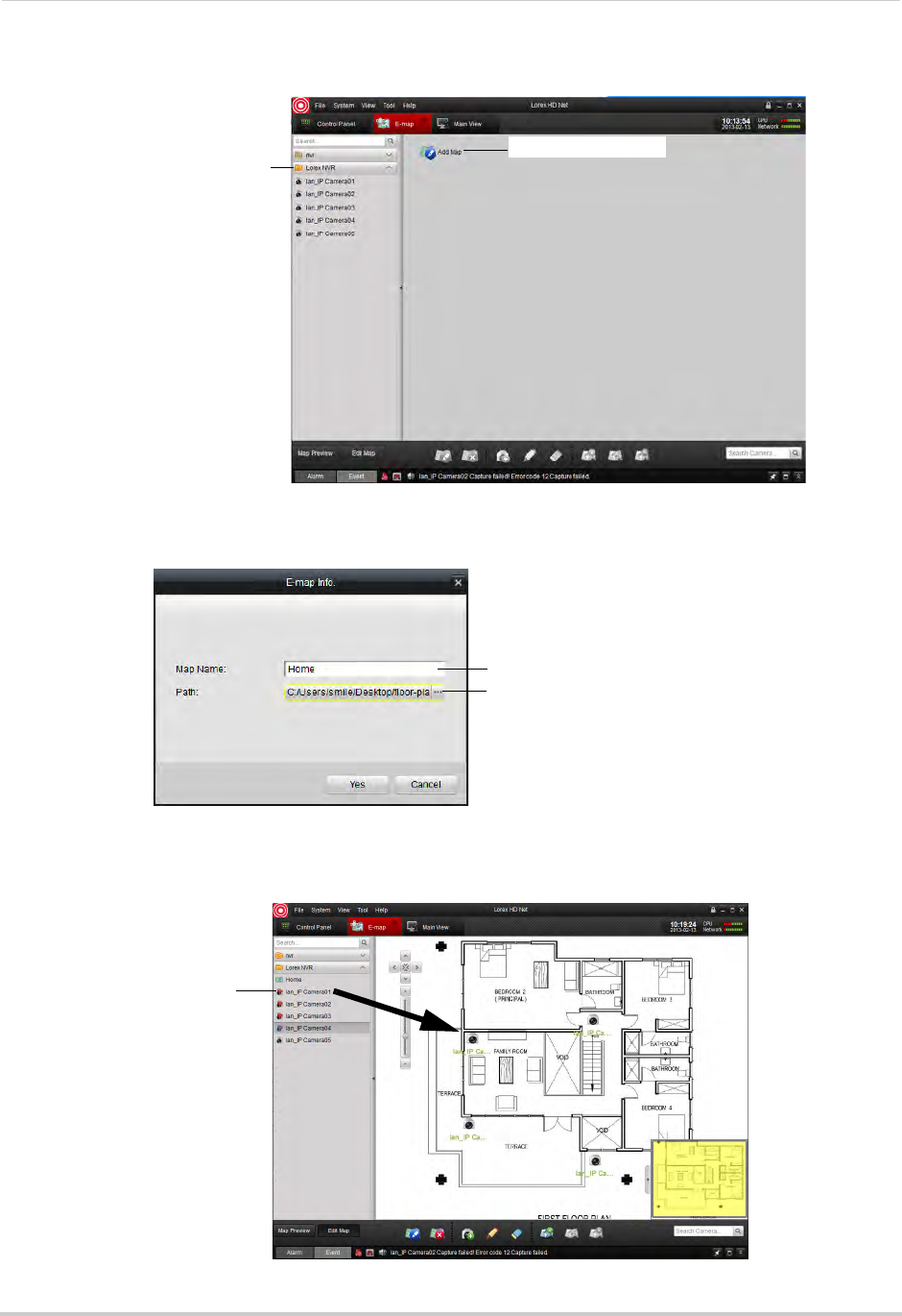
97
Client Software for PC or Mac
2Click the NVR or camera group then click Add Map.
Click the NVR or
camera group
Then click Add Map
3Enter the a name for the map. Click ..., select an image file from your computer, and then
click Open.
Enter a name for the map
Click to select an
image for the map
4Click Yes.
5Click-and-drag cameras to place them on the map.
Click and drag cameras to
add them to the map
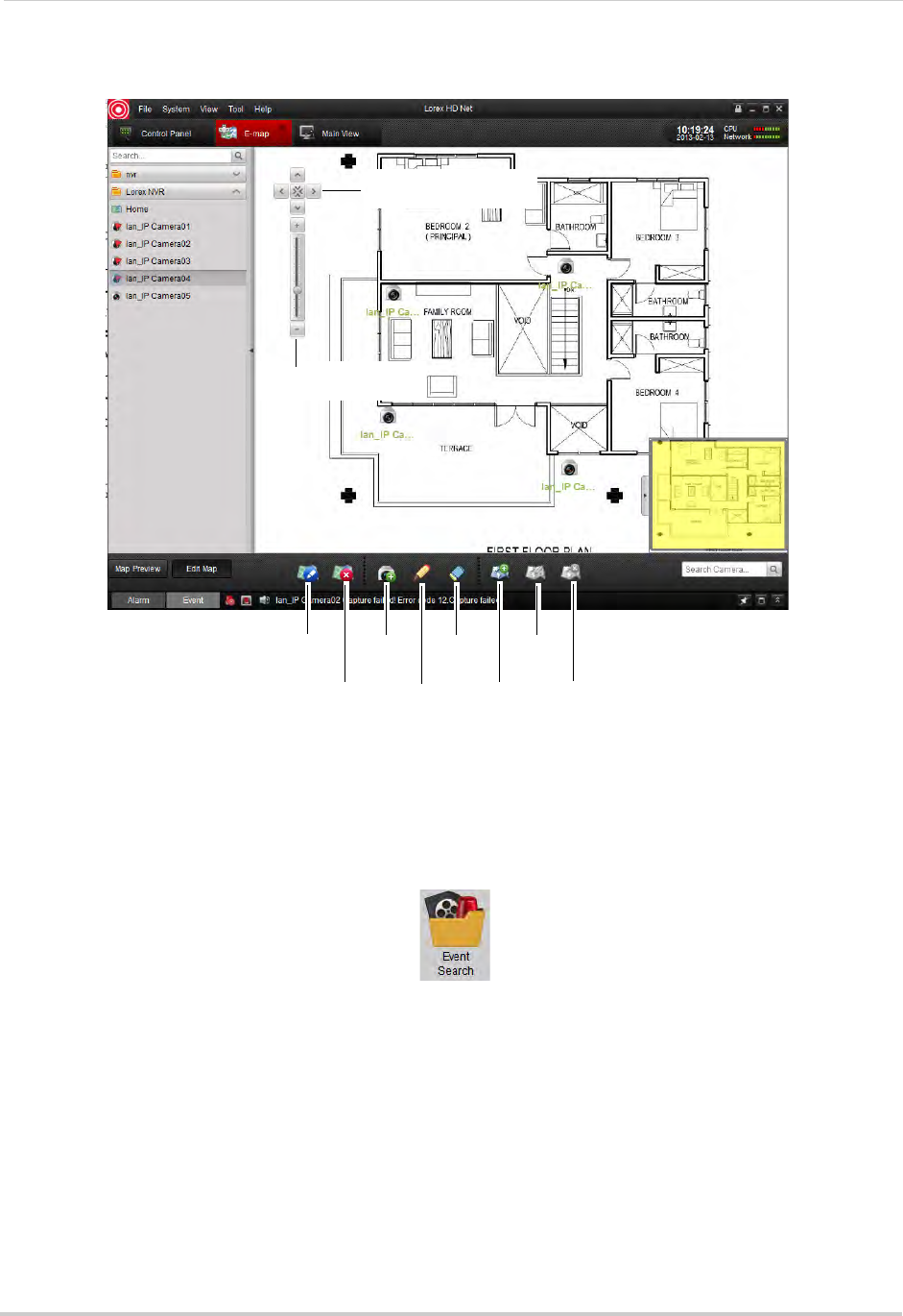
98
Client Software for PC or Mac
E-Map Controls
Edit Map
Delete Map
Add
Camera
Edit
camera
Delete
camera
Add Hot
Spot
Edit Hot
Spot
Delete
Hot Spot
Click to pan the map
Map zoom controls
Event Search
Use the Event Search to search for motion events recorded on the NVR.
To use Event Search:
1From Control Panel, click Event Search ( ).
2Perform the following to search for events:
• Under Group, select the NVR or Camera Group.
• Under Camera, select the camera you would like to search.
• Under Start Time and End Time enter the start time and end time for your search.
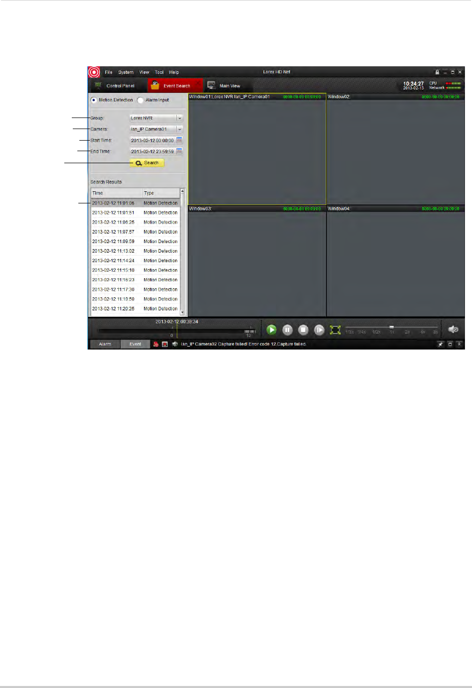
99
Client Software for PC or Mac
• Click Search. A list of relevant events appears. Double-click items in the list to playback
footage from the event.
Select NVR or
camera group
Select camera
Enter Start Time
Enter End Time
Click Search
Double click
events to playback
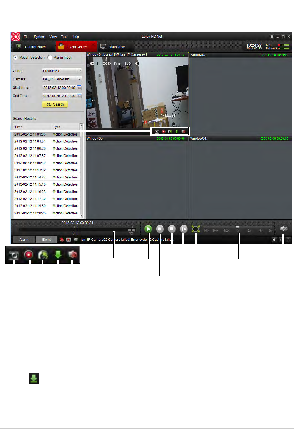
100
Client Software for PC or Mac
Event Search Controls
Click and drag to
select the
playback time
Play
Pause
Stop
Frame-by-frame
Full-screen Playback speed
Mute/unmute
Screenshot
Manual
recording
Switch
camera
Download
Mute/
unmute
Downloading Event Video Files
You can download video from events directly to your computer’s hard drive.
To download event video files:
1Perform an event search.
2Click a display area to select and hold the mouse over it to open the toolbar.
3Click to open the Download Event Video Files menu.
4Check video files and then click Download.
• To open downloaded video files, see “Using All Files to View Manual Recordings and
Downloaded Video Files” on page 93.
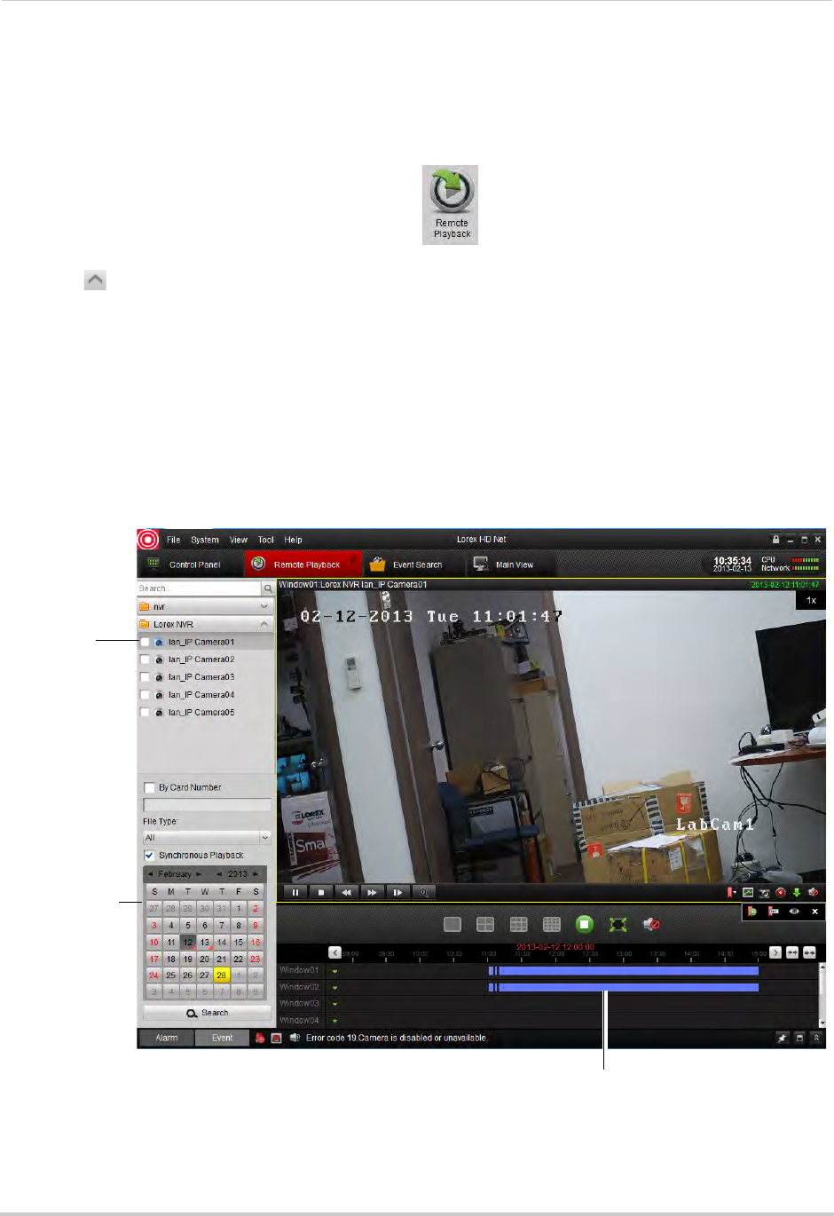
101
Client Software for PC or Mac
Remote Playback
Remote Playback allows you to view recorded video from your NVR on your computer.
To access Remote Playback:
1From Control Panel, click Remote Playback ( ).
2Click next to the NVR or camera group you would like to playback from.
3Check the cameras you would like to playback.
• Optional: Check Synchronous Playback to playback video from multiple channels at the same
time.
4In the calendar, select the day you would like to playback.
5Click Search. The time bar shows video recorded on your NVR.
6Double-click in the time bar to start playback at the selected time.
Check
cameras to
select for
playback
Select the date
in the calendar
Double-click to start playback
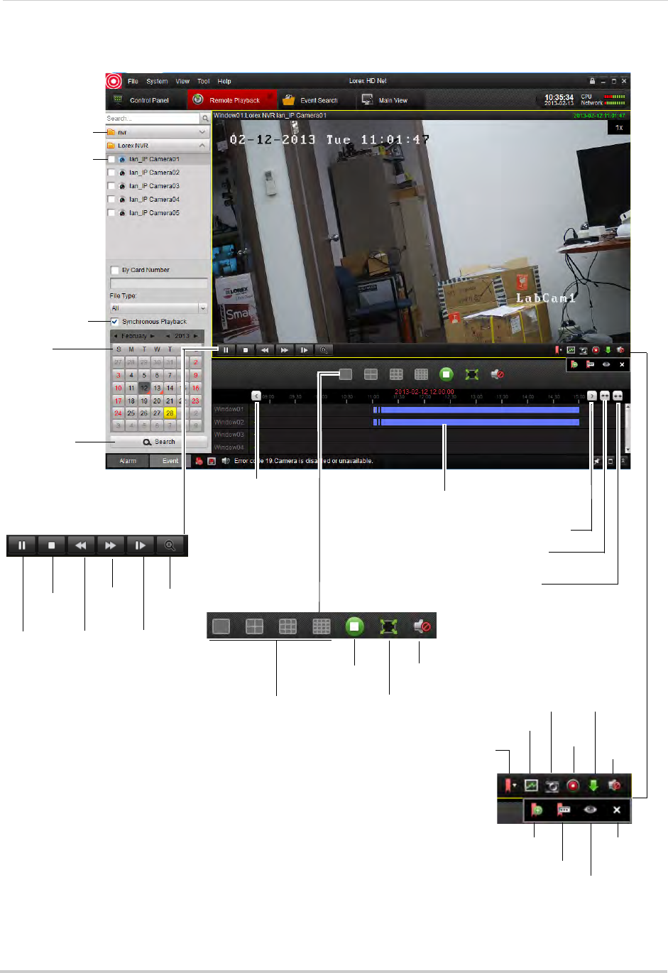
102
Client Software for PC or Mac
Remote Playback Controls
Select cameras
for playback
Select NVR or
camera group
Select
playback date
Search for
video
Enable
Synchronous
Playback
Double-click to select playback time
Previous time period
Previous time period
Expand timeline
scope
Collapse
timeline scope
Pause/play
Stop
Slow
Fast
Forward
Frame-by
-frame
Digital
zoom
Split-screen layout
Stop playback on
all channels
Full-screen
Mute/unmute
Expand tag
options
Add default
tag
Add custom
tag
Screenshot
Manual
record
Not supported
Close tag
options
Download
video
Mute/
unmute
Edit tag
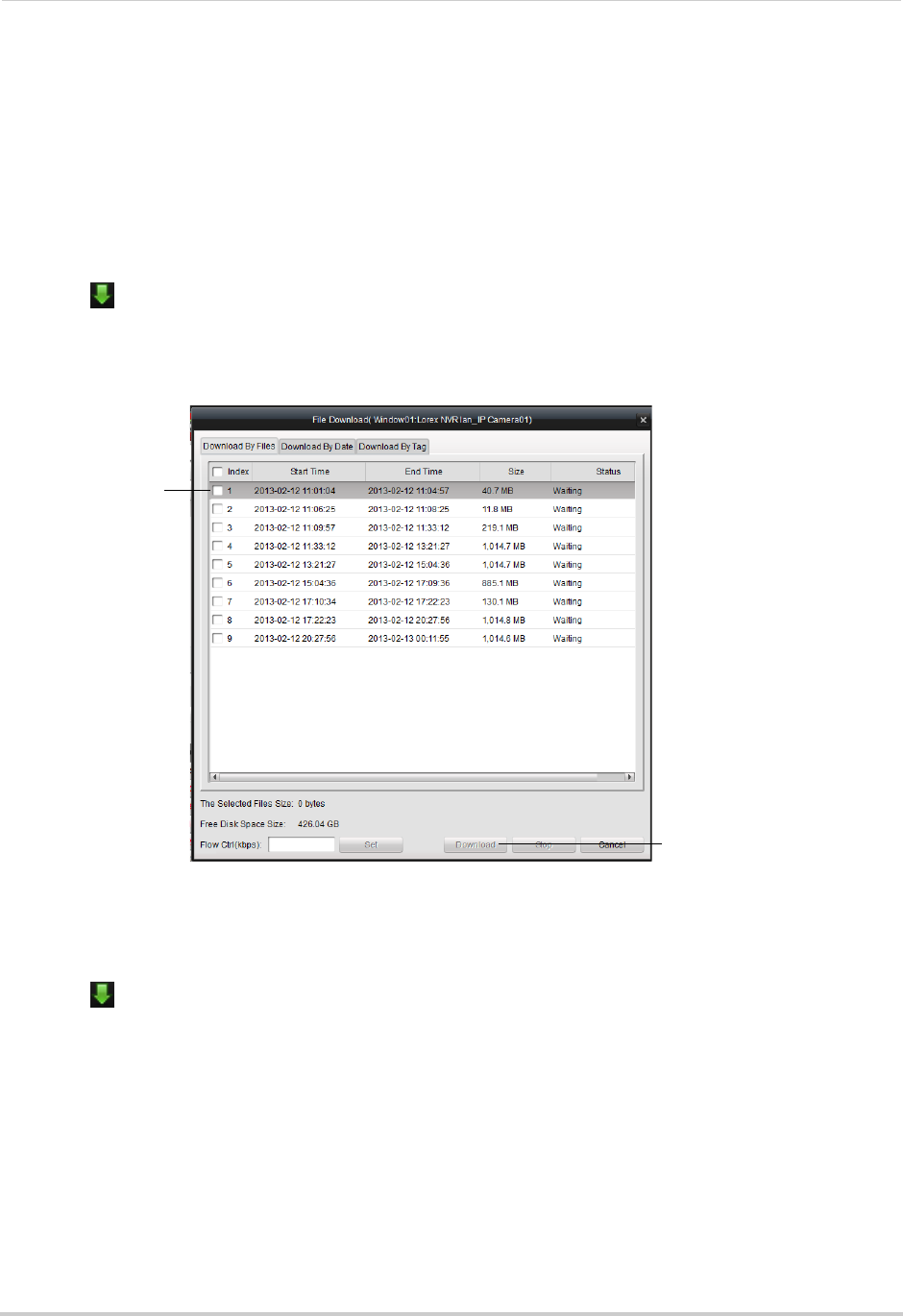
103
Client Software for PC or Mac
Downloading Video Files Using Remote Playback
You can download video files to your computer using Remote Playback in the following
ways:
• Download entire packaged video files from the NVR.
• Download video based on a specified start and end time.
• Download tagged segments of video.
To download video files by file:
1Click to open the download menu.
2Click the Download by Files tab.
3Check the files you would like to download and click Download. Wait for the files to download.
Check the video
files you would
like to download
Click Download
• To open downloaded video files, see “Using All Files to View Manual Recordings and
Downloaded Video Files” on page 93.
To download video files based on a specified duration:
1Click to open the download menu.
2Click the Download by Date tab.
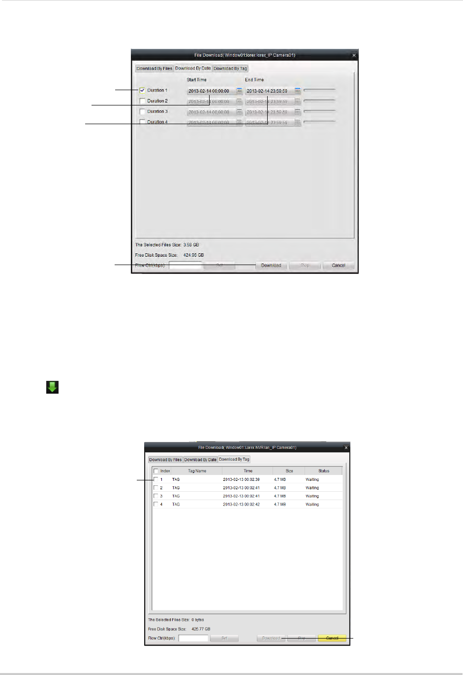
104
Client Software for PC or Mac
3Check Duration 1~4 to select up to 4 time periods to download.
Select up to 4 time periods
Select Start Time
Select End Time
Click Download
4Enter the Start Time and End Time for each selected duration.
5Click Download to download the video files. Wait for the downloads to complete.
• To open downloaded video files, see “Using All Files to View Manual Recordings and
Downloaded Video Files” on page 93.
To download files using tags:
1Click to open the download menu.
2Click the Download by Tag tab.
3Check tags to download a 1 minute video clip from the tagged time.
Check tags to select
Click Download
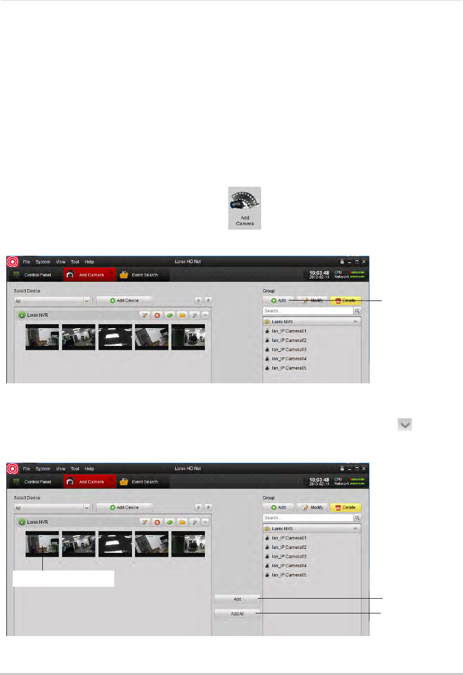
105
Client Software for PC or Mac
4Click Download to download the video files. Wait for the download to complete.
• To open downloaded video files, see “Using All Files to View Manual Recordings and
Downloaded Video Files” on page 93.
Add Camera
The Add Camera menu allows you to manage camera groups. When an NVR is added to the
client software, by default a camera group is created for it that contains all connected
cameras. Cameras from the same or different NVRs can be grouped together for simple
management.
Creating Camera Groups
1From the Control Panel, click Add Camera ( ).
2Under Group, click Add.
Click Add
3Enter a name for your group and click Yes.
4To add cameras to your camera group, expand NVRs on the left side by clicking . Then,
click the cameras you would like to add and click Add. Or, click Add All to all cameras on all
NVRs.
Add selected
camera
Click to select cameras
Add all cameras
from NVR
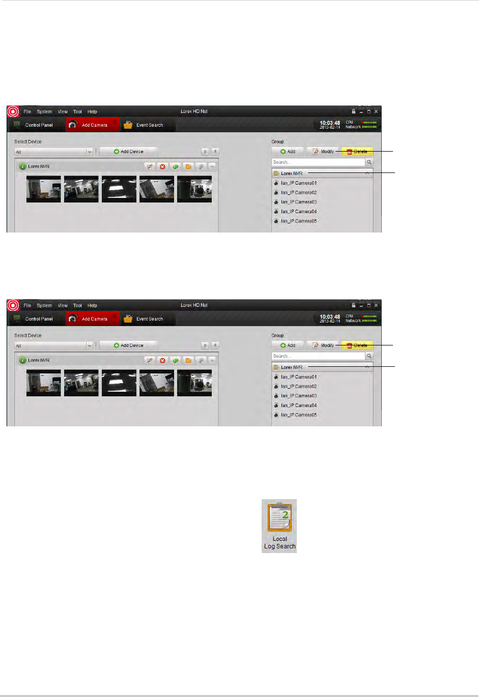
106
Client Software for PC or Mac
Modifying Cameras or Camera Groups
You can change the name of a camera or camera group that is used in the client software.
To modify a camera or camera group:
1Click the camera or camera group on the left then click Modify.
Click camera or
camera group
Click Modify
2Enter a new name for the camera or camera group and then click Yes.
Deleting Cameras or Camera Groups
• Click the camera or camera group you would like to delete and click Delete. Click Yes
Click camera or
camera group
Click Delete
Local Log Search
The Local Log Search allows you to search for logs from your NVRs.
To search for logs:
1From the Control Panel, click Local Log Search ( ).
2Configure the following search options:
• Log Type: Select Alarm for motion detection alarms and system warning logs, Operation for
operations logs, such as configuration changes, or System for logs of user access to the
system (e.g. log-ins and log-outs).
• Minor Type: Select All to search for all logs in the Log Type you have selected or select a
specific type of log to search for.
• User Name: Select All Users to search for logs generated by all users or select a specific
user to see logs generated by that user.
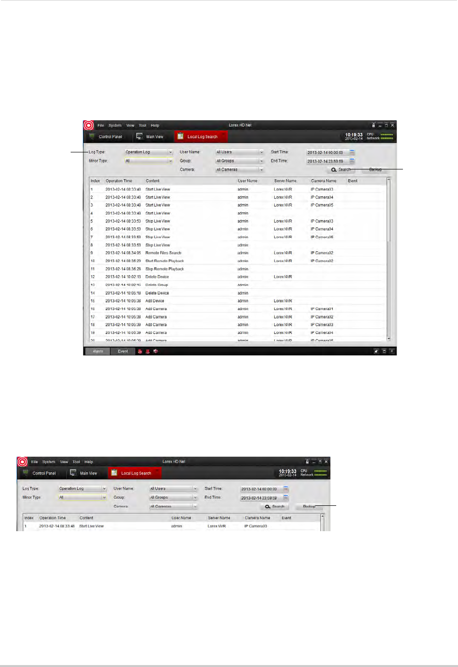
107
Client Software for PC or Mac
• Group: Select the NVR or camera group you would like to search for logs on or select All
Groups to search for logs from all NVRs and camera groups.
• Camera: Select the camera you would like to search for logs from or select All Cameras to
search for logs from all cameras.
• Start Time/End Time: Select the start and end time for your search.
3Click Search. All logs that meet your search parameters appear in the list.
Configure search
parameters
Click Search
Backing up Logs
You can backup log search results to your computer hard drive.
To back up logs:
1Perform a search using the steps above.
2Click Backup.
Click Backup
3Click ... to select a download folder for your logs. Enter a file name and click Save.
Account Management
The Account Management menu allows you to create user accounts for the client software.
To enable password protection for the client software, see “General” on page 129.
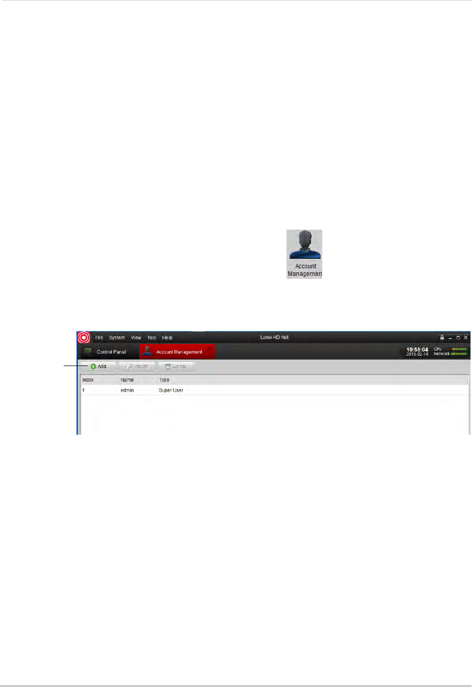
108
Client Software for PC or Mac
The client software has the following types of user accounts:
• Super User: The Super User account is logged in by default when you first run the client
software. This is a unique account that has full control over all software and NVR functions.
The Super User may add, modify, or delete any user account.
NOTE: The default user name for the Super User is admin and the default password is also
admin.
• Administrator: Administrator accounts have access to all NVR and software functions by
default. They may add, modify, or delete Operator accounts, but cannot change accounts of
other administrators.
• Operator: The Operator is a standard user account. Operator accounts have only the NVR
permissions they are given and cannot change software settings or change other user
accounts. Operators may change their own password.
To access Account Management:
• From the Control Panel, click Account Management ( ).
Adding User Accounts
1Click Add.
Click Add
2Configure the following:
• Under User Type, select Administrator or Operator.
• Under Password, enter a password for the user account. Repeat the password under Confirm.
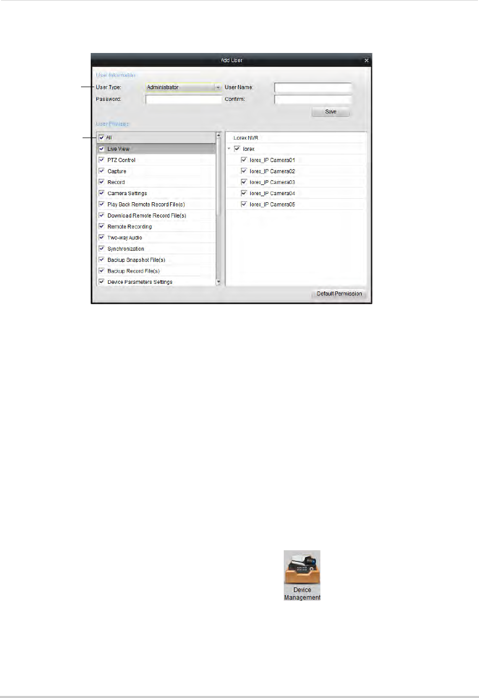
109
Client Software for PC or Mac
• In the bottom area, check the permissions you would like to assign to the user account.
Configure
account settings
Select
permissions
3Click Save to create the user account.
Modify User Accounts
1Click the account you would like to modify and then click Modify.
2Edit the user account settings and permissions as needed and click Save when finished.
Delete User Accounts:
• Click the account you would like to delete and then click Delete.
Device Management
The Device Management menu allows you to add or remove NVRs from the client software.
It also allows you to remotely configure your NVRs.
NOTE: For details on adding NVRs to the Client Software, see “Connecting to Your NVR Over
the Internet on PC or Mac” on page 83.
To access Device Management:
• From the Control Panel, click Device Management ( ).
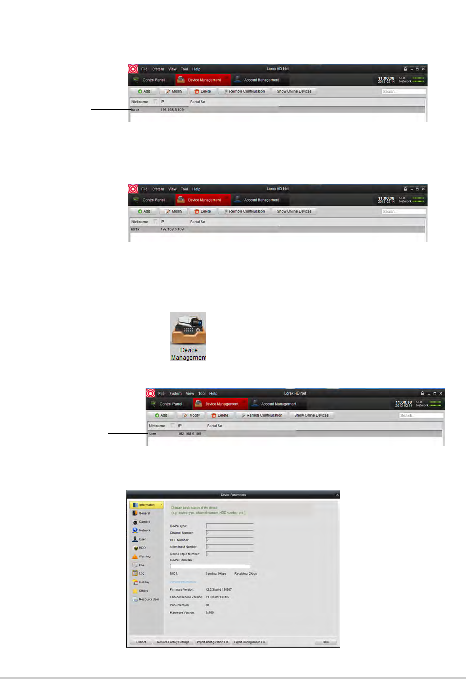
110
Client Software for PC or Mac
Modifying an NVR
1Click the NVR you would like to modify and click Modify.
Click the NVR
Click Modify
2Change the connection info as needed and click Modify.
Deleting an NVR
• Click the NVR you would like to delete and click Delete. Click Yes to confirm.
Click the NVR
Click Delete
Configuring an NVR Through Device Management
You can configure your NVRs settings through the client software.
To configure NVR settings:
• From the Control Panel, click .
• Click the NVR you would like to configure and click Remote Configuration. See below for
details on available settings.
Click the NVR
Click Remote Configuration
Information
The Information sub-menu shows system information about the NVR.
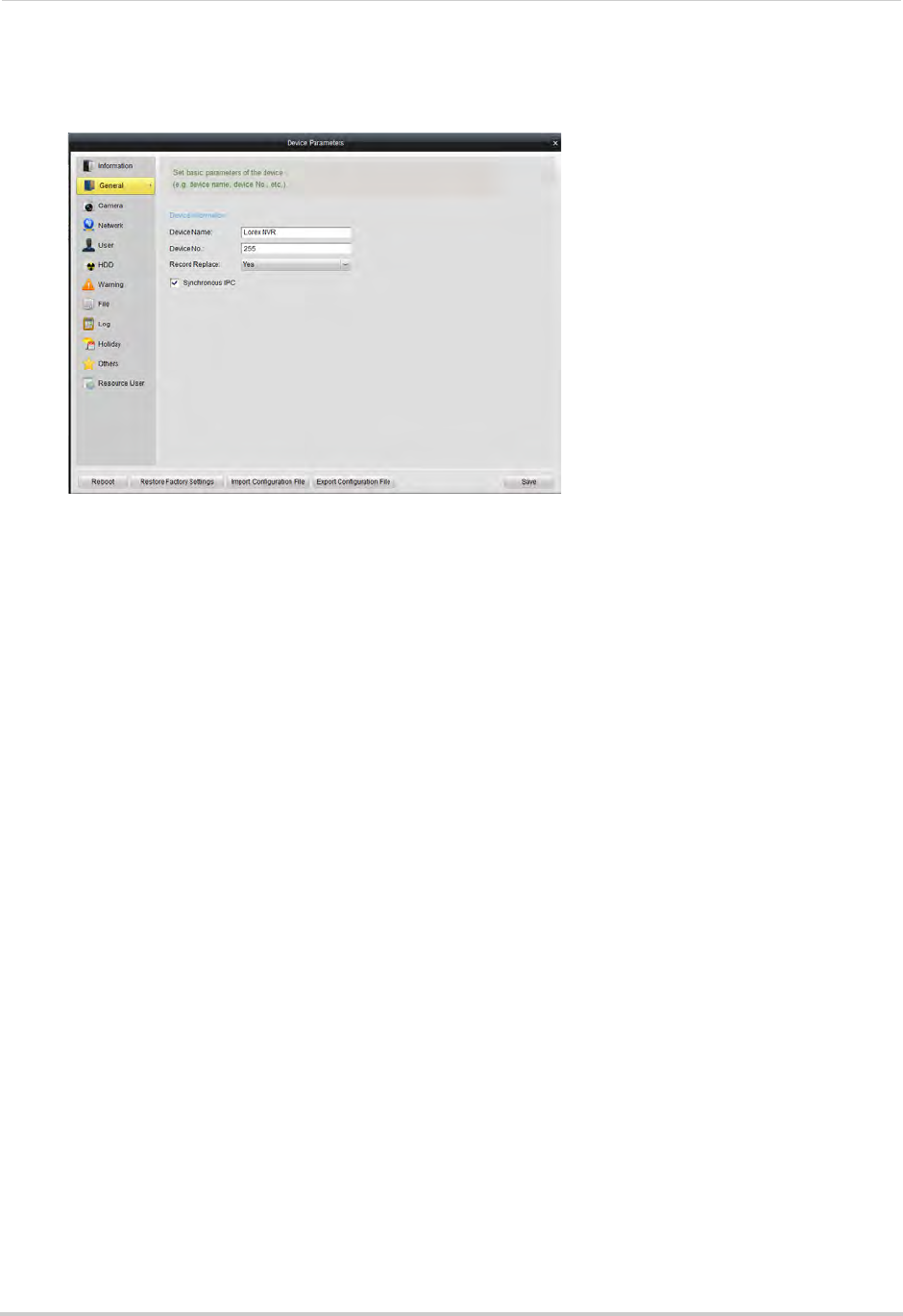
111
Client Software for PC or Mac
General
The General sub-menu allows you to configure general system settings.
To configure general settings:
1Configure the following:
• Device Name: Enter a name for your NVR.
• Device No.: Enter the ID for the remote control. For details, see “Pairing the Remote Control”
on page 68.
• Record Replace: Select Yes to enable overwrite, or select No to disable overwrite.
• Syncronous IPC: Make sure this is checked.
2Click Save to save changes.
Camera
NOTE: Do not change any settings in this sub-menu. To configure camera settings, see
“Camera Settings” on page 117.
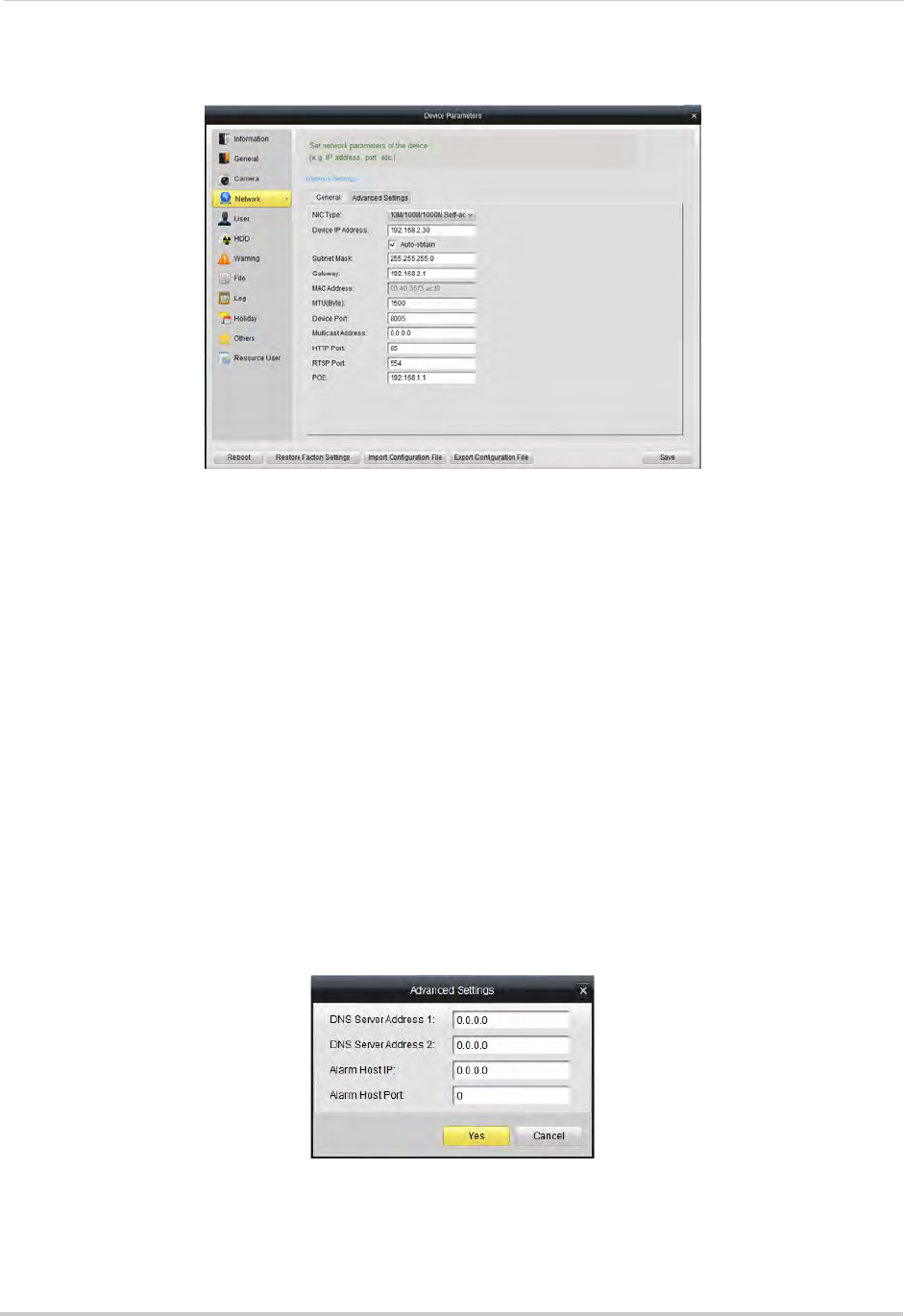
112
Client Software for PC or Mac
Network
The Network sub-menu allows you to configure networking settings. The Network
sub-menu is divided into the following tabs:
The General tab allows you to configure the IP address of the NVR for fixed IP or DHCP
mode. It also allows you to configure system port numbers.
The Advanced tab allows you to configure additional advanced networking settings.
To configure your NVR’s IP address for fixed IP or DHCP mode:
1Select the General tab.
2Check Auto-obtain to use DHCP mode and have the router automatically assign an IP
address to the NVR. Un-check to use a fixed IP address to your NVR.
3If you un-check Auto-obtain:
• Under Device IP Address, enter the IP address your NVR will use. Please note that additional
configuration may be required on your router. See your router’s user manual for details.
• Under Subnet Mask, enter the subnet mask.
• Under Gateway, enter the default gateway address.
• Click Advanced Settings>Advanced Settings. Under DNS Server Address 1 & 2, enter the
DNS address and click Yes.
4Click Save. Your NVR may restart.
NOTE: If you change the NVR’s IP address and you have configured port forwarding, you will
need to re-configure it using the newly selected IP address.
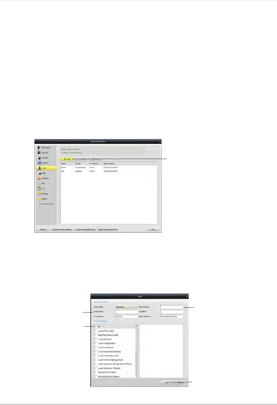
113
Client Software for PC or Mac
To configure your NVR’s system ports:
1Select the General tab.
2Configure the following:
• Device Port: Enter the desired Client port (default: 8000).
• HTTP Port: Enter the desired HTTP port (default: 80).
• RTSP Port: Enter the desired Mobile port (default: 1025).
3Click Save to save changes.
User
The User sub-menu allows you to configure user accounts on the NVR.
Adding Users
1Click Add.
Click Add
2Under User Name, enter the user’s account name.
3Under Password and Confirm, enter the user’s password.
4At the bottom of the screen, select permissions that will apply to the user account.
5Click Yes to save the user account.
Enter User Name
Enter Password
Select permissions
Click Yes
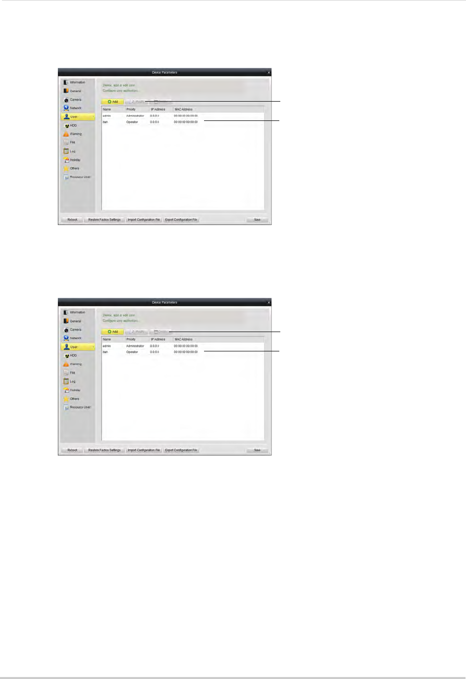
114
Client Software for PC or Mac
Modifying Users
1Click the user account and then click Modify.
Click Modify
Click user account
2Modify the account details as necessary and then click Yes.
Deleting Users
•
Click Delete
Click user account
Click the user account you would like to delete and then click Delete. Click Yes to confirm.
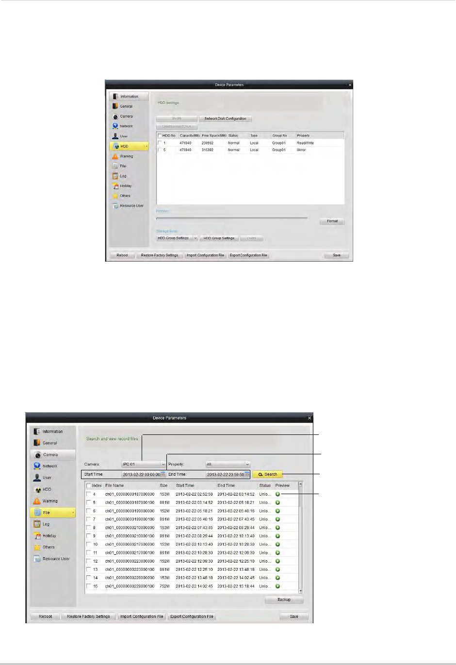
115
Client Software for PC or Mac
HDD
The HDD sub-menu allows you to configure settings for hard drives installed in your NVR.
For more information on available hard drive settings, see “HDD” on page 44.
File
The File sub-menu allows you to search for video files on your NVR.
To search for video files on your NVR:
1Under Camera, select the camera you would like to search.
2Under Start Time and End Time, select the start and end times for your search.
3Click Search.
4Click to playback video files.
Click to playback
Click to search
Select Start Time
and End Time
Select Camera
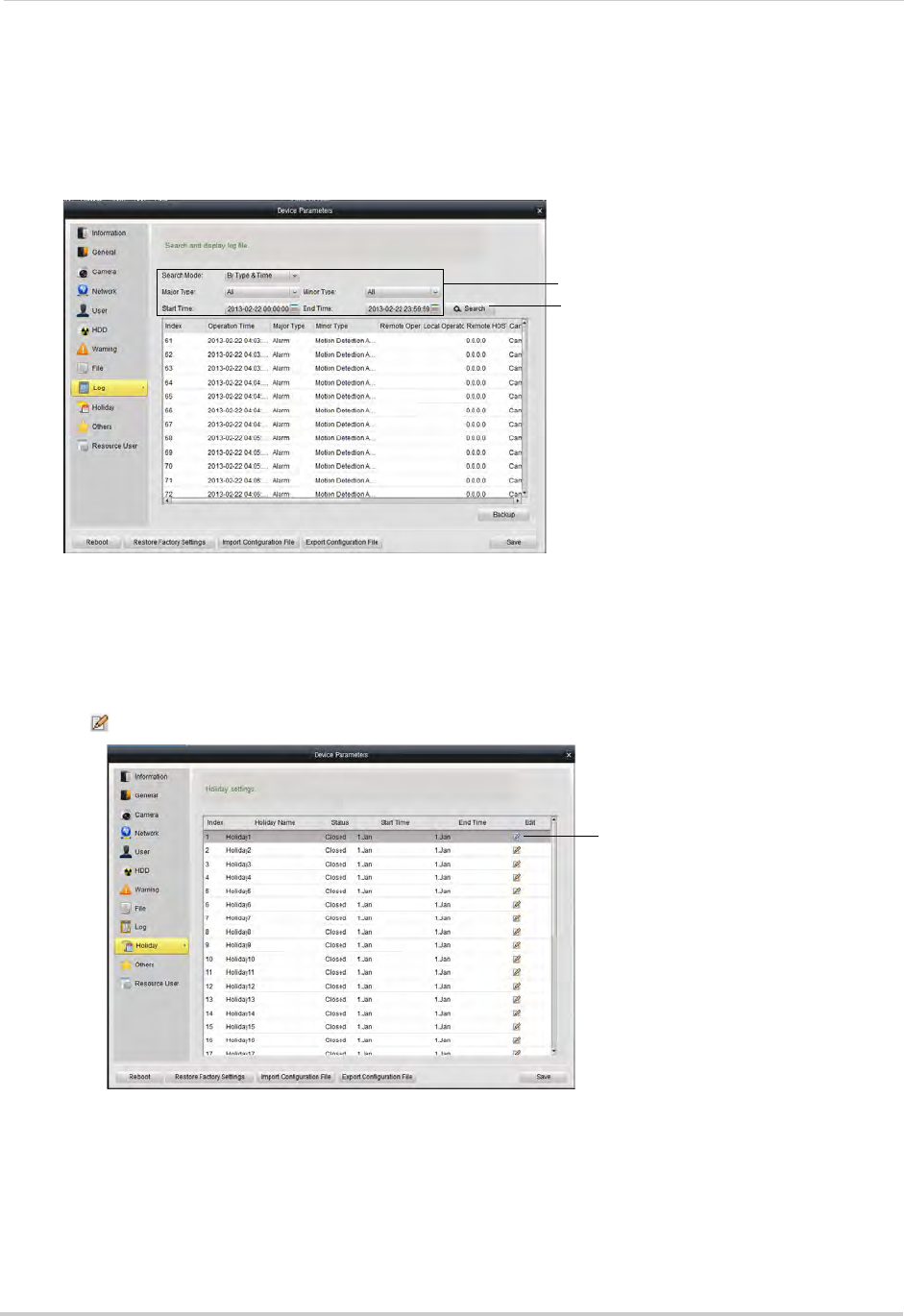
116
Client Software for PC or Mac
Log
The Log sub-menu allows you to search for system logs from your NVR.
To search for system logs:
• Select the search criteria and click Search.
Select search criteria
Click Search
Holiday
The Holiday sub-menu allows you to mark days as holidays. Holidays receive a special
recording schedule. For details, see “Configuring the Recording Schedule” on page 50.
To select holidays:
1Click next to the holiday you would like to configure.
Click to configure
holiday
2Check Enable Holiday.
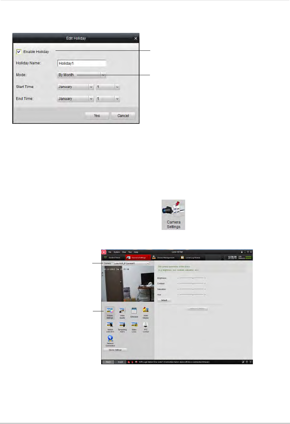
117
Client Software for PC or Mac
3Select the date for the holiday.
Check Enable Holiday
Select holiday date
4Click Yes.
5Click Save.
Camera Settings
The Camera Settings menu allows you to configure settings for connected cameras.
To access Camera Settings:
• From the Control Panel, click Camera Settings ( ).
• To configure cameras, select the camera under Camera and click the icons to select different
menus.
Select camera
Select settings menus
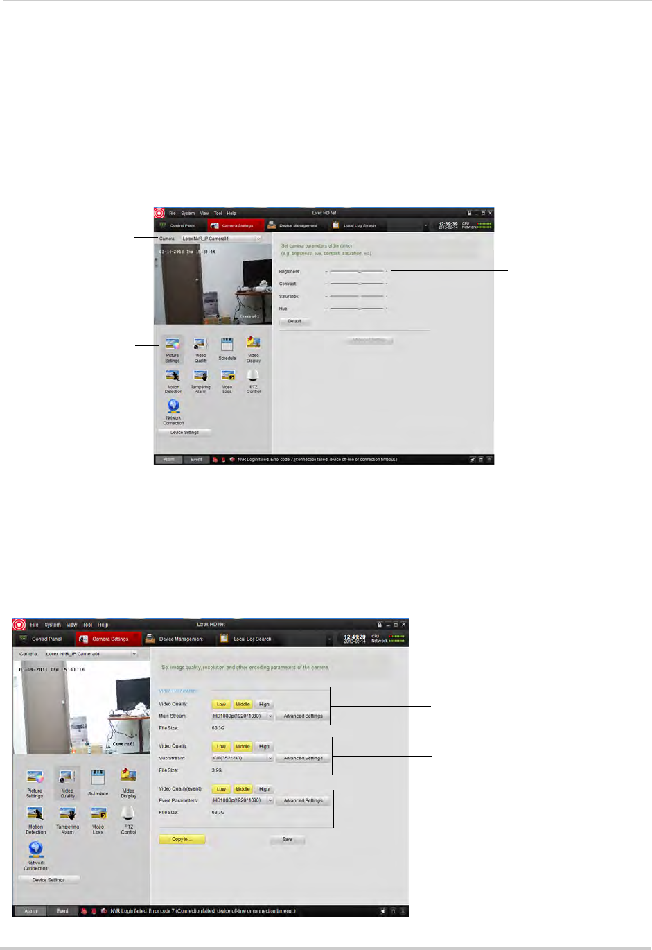
118
Client Software for PC or Mac
Adjusting Picture Settings
Picture Settings allows you to configure image settings for your cameras.
To configure image settings:
1Under Camera, select the camera you would like to configure.
2Click Picture Settings.
3Adjust the Brightness, Contrast, Saturation, and Hue as needed.
Select camera
Click Picture Settings
Adjust Brightness,
Contrast, Saturation,
and Hue
Configuring Video Quality
Video Quality allows you to configure the resolution, frame rate, and other video quality
settings
The Video Quality settings allows you to configure the settings for Continuous Recording
(Main Stream), Event Recording (Event), and Sub Stream (for streaming to computers and
mobile devices).
Main Stream (Continuous
Recording) settings
Sub Stream (Remote
Streaming) settings
Event Stream (Event
Recording) settings

119
Client Software for PC or Mac
To configure video quality:
1Under Camera, select the camera you would like to configure.
2Click Video Quality.
3Configure the settings for the Main Stream, Sub Stream, and Event Stream:
• Video Quality: Select Low, Medium, or High quality settings for each stream.
• Main Stream/Sub Stream/Event Parameters: Select the desired resolution for each stream.
• Advanced Settings: Allows you to adjust the frame rate, bitrate, and other advanced settings
for each stream.
4(Optional) Use the Copy to button to copy settings to other cameras.
5Click Save to save changes.
Configuring Camera Recording Schedules
Use the recording schedule to configure when cameras will record continuously or using
motion detection only.
To configure camera recording schedules:
1Under Camera, select the camera you would like to configure.
2Click Schedule.
3Check Local Recording to enable recording for the selected camera or un-check to disable.
4By default, the recording schedule is set for Continuous & Motion Recording 24/7. To
customize the recording schedule, click All Day Template. Select one of the following
options.
• All-day Template: Enable Continuous & Motion Recording 24/7.
• Weekday Template: Enable Continuous & Motion Recording during working hours (9-5
Mon-Fri) only. Do not record outside these hours.
• Alarm Template: Enable Motion Recording only 24/7.
• Select one of the standard templates or select Template01~08 and click Edit to create a
custom template. Click the recording options at the top of the screen and click and drag
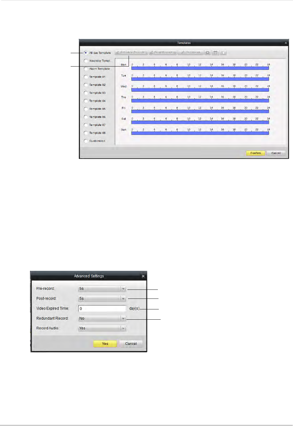
120
Client Software for PC or Mac
on each day to enable times for the selected recording type. Click Save when finished
making changes.
Select a schedule
Select recording types to
add to schedule
• Click Confirm to save changes.
5(Optional) Use the Copy to button to copy the schedule to other cameras.
6Click Save to save changes.
To configure advanced recording options:
1Under Camera, select the camera you would like to configure.
2Click Schedule.
3Click Advanced Settings.
4Configure the following:
Configure Pre-recording time
Configure Post-recording time
Select time to retain footage
Enable mirror recording (mirror hard
drive required; not included)
• Pre-record: Select the duration the NVR will record before events.
• Post-record: Select the duration the NVR will record after events.
• Video Expired Time: Select the duration the NVR will retain recorded footage. Note that the
hard drive must be large enough to keep footage for this duration.
• Redundant Record: Select Yes to enable the camera to record to the mirror hard drive (not
included). You must have a mirror hard drive installed and configured to use this feature.

121
Client Software for PC or Mac
• Record Audio: Not supported.
5Click Yes to confirm changes.
6(Optional) Use the Copy to button to copy the schedule to other cameras.
7Click Save to save changes.
Configuring the Camera Video Display (OSD) and Privacy Masks
The Video Display menu allows you to configure the text on the camera on-screen display
(OSD). You may also customize the position of OSD text or configure Privacy Masks to block
out areas of the screen from recording.
To configure the camera on-screen display:
1Under Camera, select the camera you would like to configure.
2Click Video Display.
3Configure the following, as needed:
• Check Display Name to show the Camera Name on the monitor or un-check to hide the
Camera Name.
• Under Camera Name, enter a custom name for the camera.
• Check Display Date to show the date and time on the monitor or un-check to hide.
• Under Date Format, select the desired date format: MM-DD-YYYY, YYYY-MM-DD, or
DD-MM-YYYY.
• Under Time Format, select 12-hour or 24-hour time format.
• Check Display Week to show the day of the week in the time display.
• Under OSD Attribute, select the appearance of the OSD text.
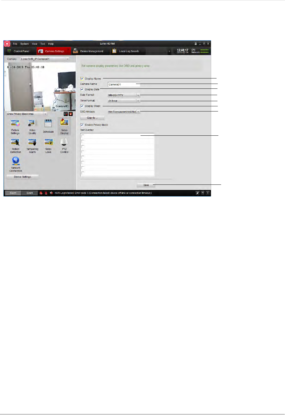
122
Client Software for PC or Mac
• Under Text Overlay, you may enter custom messages to display on the monitor. Check entries
to have them appear on the screen. They will appear on the monitor when you save changes.
Show/hide camera name
Enter camera name
Show/hide date and time
Select Date Format
Select Time Format
Show day of the week
Show OSD appearance
Enter custom messages
Save changes
4(Optional) Use the Copy to button to copy your settings to other cameras.
5Click Save to save changes.
To change the position of OSD text:
1Under Camera, select the camera you would like to configure.
2Click Video Display.
3Click the drop-down menu under the video display and select Insert OSD/Camera Name/
Text.
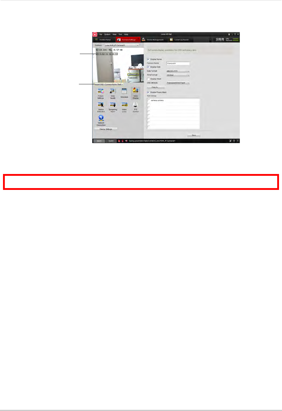
123
Client Software for PC or Mac
4OSD messages are outlined. Click-and-drag messages to change their position.
Select Insert OSD/
Camera Name/Text
Click and drag to change the
position of OSD text
5Click Save to save changes.
To configure Privacy Areas:
ATTENTION: Areas covered in privacy masks are not visible in recordings.
1Under Camera, select the camera you would like to configure.
2Click Video Display.
3Check Enable Privacy Mask to enable privacy masks or un-check to disable.
4Click the drop-down menu under the video display and select Insert OSD/Camera Name/
Text.
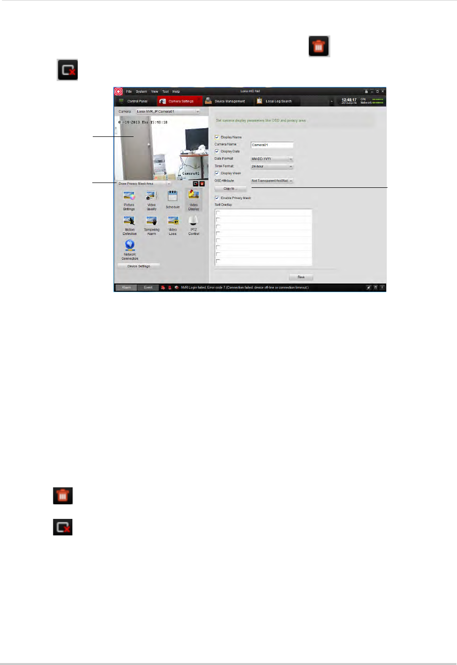
124
Client Software for PC or Mac
5Click-and-drag in the video display to add privacy areas. Click to delete all privacy areas
or click to delete the selected privacy area.
Click-and-drag to add
privacy areas
Check to enable
privacy masks
Select Draw Privacy
Mask Area
6Click Save to save changes.
Configuring Motion Detection Settings
The Motion Detection menu allows you to configure motion detection settings for your
cameras.
To configure motion detection settings:
1Under Camera, select the camera you would like to configure.
2Click Motion Detection.
3Check Enable Motion Detection to enable motion detection on the selected camera or
un-check to disable.
4To customize areas where motion detection is enabled:
• Click to clear all motion detection areas.
• Click-and-drag to enable sections of the screen for motion detection.
• Click to delete the selected section.
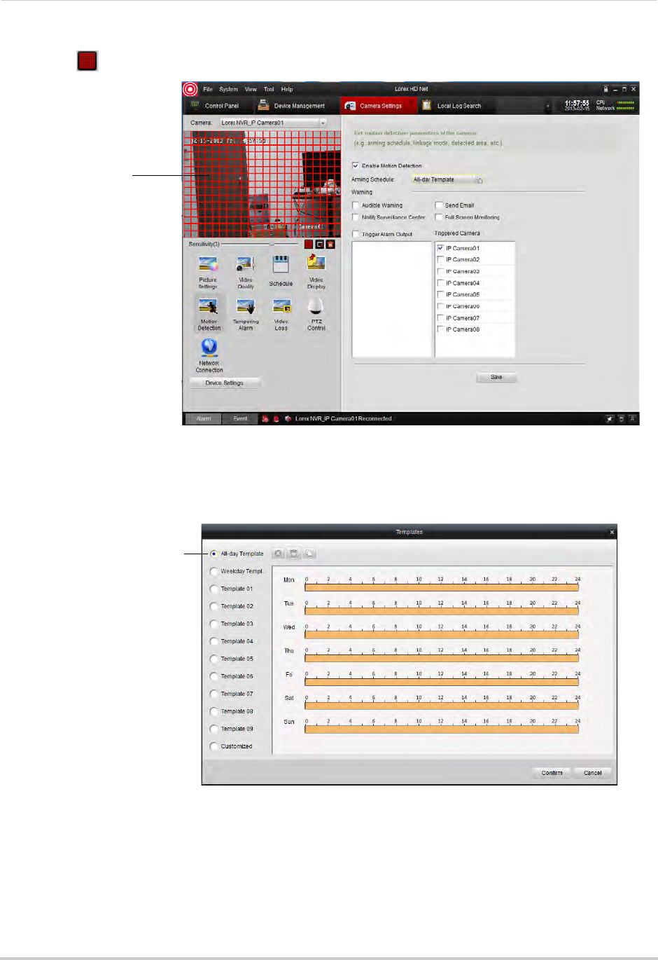
125
Client Software for PC or Mac
• Click to select the entire display area.
Configure motion
detection areas
5To change the motion detection sensitivity, adjust the Sensitivity slider.
6By default, motion detection is enabled 24/7. If you want to configure times when motion
detection is enabled, click All Day Template.
Select or customize motion
schedule for the selected
camera
• In the Templates menu, times when motion detection is enabled are shown as orange. Select
one of the following:
• All-day Template: Enable motion detection 24/7.
• Weekday Template: Enable motion detection during working hours (9-5 Mon-Fri) only.
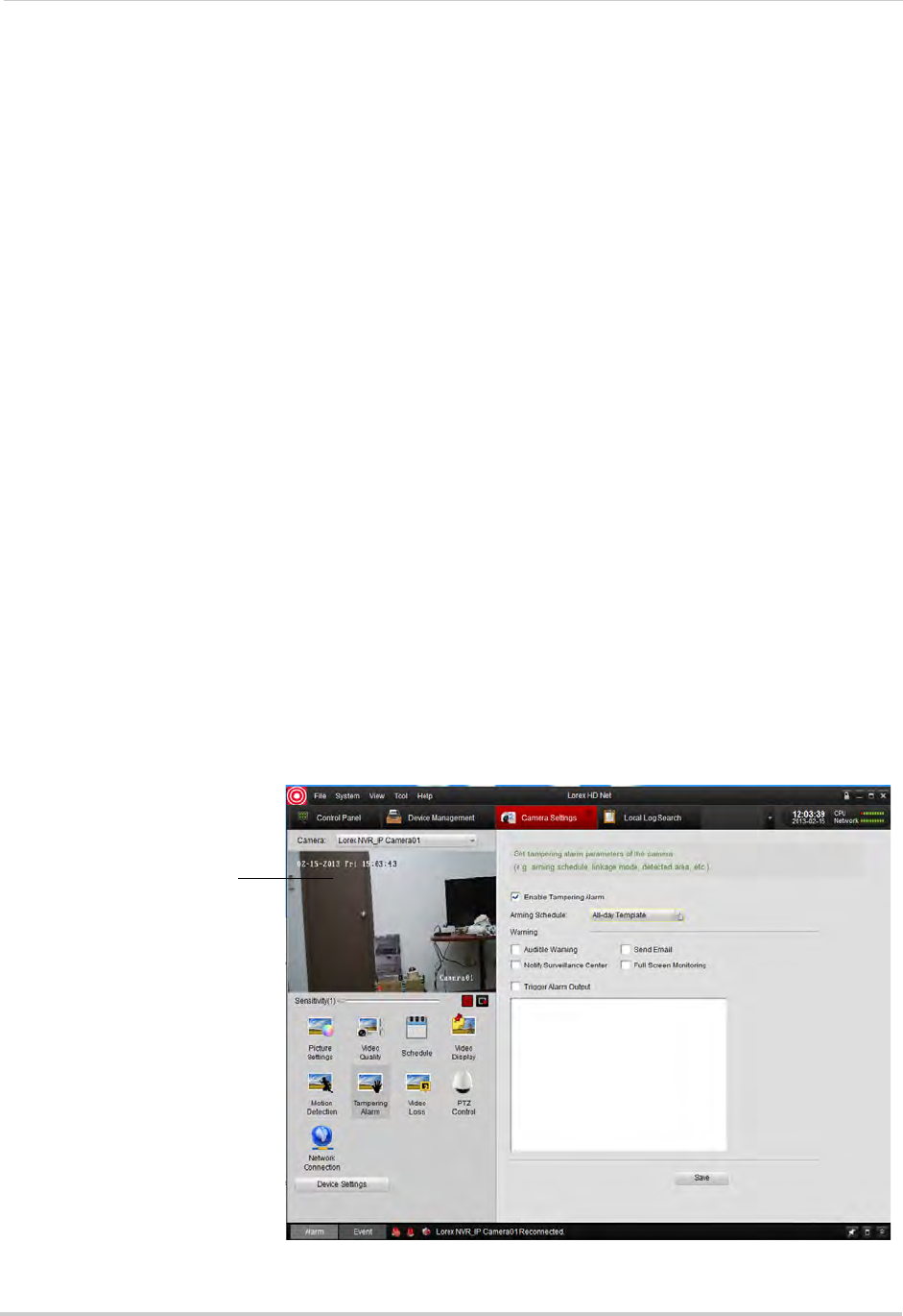
126
Client Software for PC or Mac
• Select one of the standard templates or select Template01~08 and click Edit to create a
custom template. Click and drag on each day to configure when motion detection is
enabled. Click Save when finished making changes.
• Click Confirm to save changes to the schedule.
7Under Warning, check to enable the following warnings when motion is detected:
• Full Screen Monitoring: The selected channel will open in full screen.
• Audible Warning: System will beep.
• Notify Surveillance Center: An alert will be sent to the client software.
• Send Email: An alert email will be sent. Note that you must set up email alerts. For details,
see “Configuring Email Alerts” on page 70.
8Under Triggered Camera, select which channels will start to record when motion detection is
triggered on the selected channel.
9Click Save to save changes.
Configuring Tampering Alarm Settings
The Tampering Alarm is activated if the camera lens is covered, for example if a vandal
sprays paint on the camera.
To configure Tampering Alarm settings:
1Under Camera, select the camera you would like to configure.
2Click Tampering Alarm.
3Check Enable Tampering Alarm to enable the Tampering Alarm on the selected camera or
un-check to disable.
4Click and drag in the video display area to enable areas the camera will watch for tampering.
Click and drag to select
Tampering Alarm areas
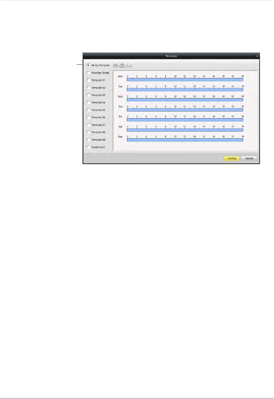
127
Client Software for PC or Mac
5To change the Tampering Alarm sensitivity, adjust the Sensitivity slider.
6When Tampering Alarms are enabled, they are enabled 24/7 by default. If you want to
configure times when they are enabled, click All Day Template.
Select or customize
Tampering Alarm schedule
for the selected camera
• In the Templates menu, times when Tampering Alarms are enabled are shown as light blue.
Select one of the following:
• All-day Template: Enable Tampering Alarms 24/7.
• Weekday Template: Enable Tampering Alarms during working hours (9-5 Mon-Fri) only.
• Select one of the standard templates or select Template01~08 and click Edit to create a
custom template. Click and drag on each day to configure when motion detection is
enabled. Click Save when finished making changes.
• Click Confirm to save changes to the schedule.
7Under Warning, check to enable the following warnings when the Tampering Alarm is
triggered:
• Full Screen Monitoring: The selected channel will open in full screen.
• Audible Warning: System will beep.
• Notify Surveillance Center: An alert will be sent to the client software.
• Send Email: An alert email will be sent. Note that you must set up email alerts.
8Click Save to save changes.
Configuring Video Loss Alarms
Video Loss Alarms occur if the connection between the NVR and cameras is lost (for
example, if the ethernet cable is disconnected).
To configure Video Loss alarms:
1Under Camera, select the camera you would like to configure.
2Click Video Loss.
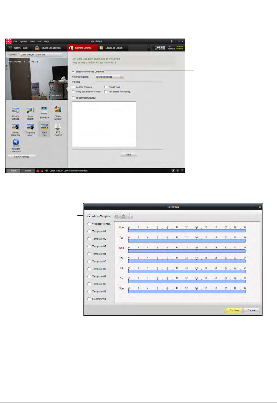
128
Client Software for PC or Mac
3Check Enable Video Loss Detection to enable the Video Loss Alarms on the selected camera
or un-check to disable.
Check to enable video
loss alarms
4When Video Loss alarms are enabled, they are enabled 24/7 by default. If you want to
configure times when they are enabled, click All Day Template.
Select or customize Video
Loss alarm schedule for the
selected camera
• In the Templates menu, times when Video Loss alarms are enabled are shown as light blue.
Select one of the following:
• All-day Template: Enable Video Loss Alarms 24/7.
• Weekday Template: Enable Video Loss Alarms during working hours (9-5 Mon-Fri) only.
• Select one of the standard templates or select Template01~08 and click Edit to create a
custom template. Click and drag on each day to configure when video loss alarms are
enabled. Click Save when finished making changes.
• Click Confirm to save changes to the schedule.
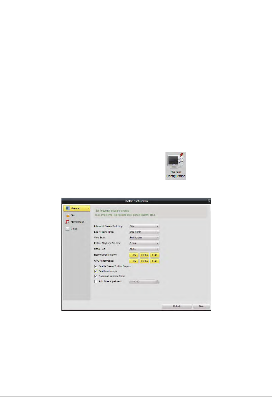
129
Client Software for PC or Mac
5Under Warning, check to enable the following warnings when the Video Loss Alarm is
triggered:
• Full Screen Monitoring: The selected channel will open in full screen.
• Audible Warning: System will beep.
• Notify Surveillance Center: An alert will be sent to the client software.
• Send Email: An alert email will be sent. Note that you must set up email alerts.
6Click Save to save changes.
PTZ Control (Not Supported)
Network Connection (Not Supported)
System Configuration
The System Configuration menu allows you to configure settings for the Client Software.
To access System Configuration:
• From the Control Panel, click System Configuration ( ).
General
To configure General client options:
1Configure the following:
• Interval of Screen Switching: Select the time channels will be shown in Main View before
switching when Sequence mode is on.
• Log Keeping Time: Select the amount of time the client software will retain system logs.
• View Scale: Select the aspect ratio for your cameras: Full-screen (may cause image
stretching), 4:3, or 16:9.
• Network Performance: Select Low, Middle, or High.
• CPU Performance: Select Low, Middle, or High.
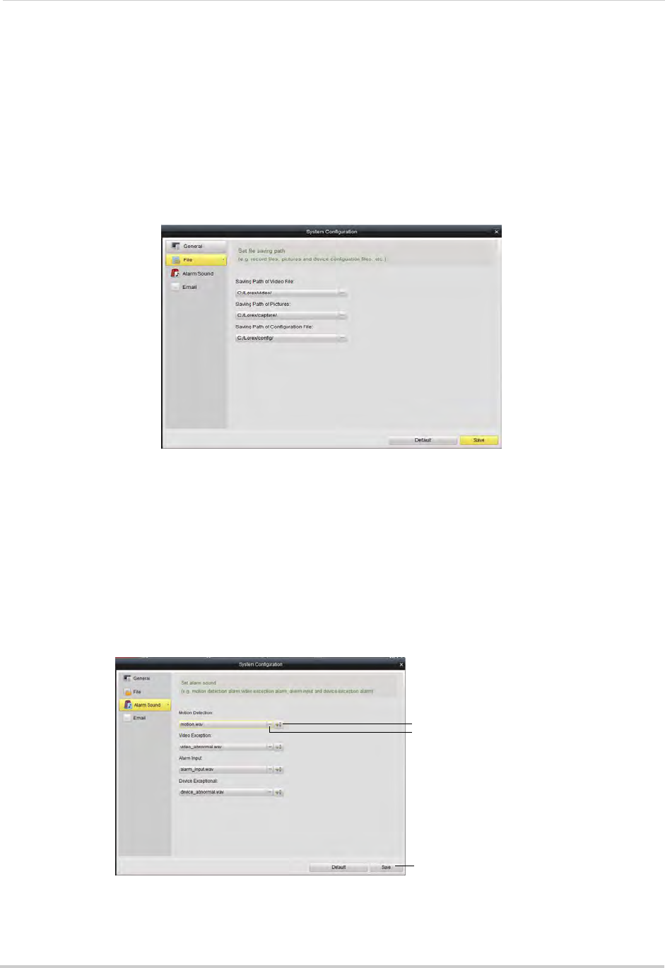
130
Client Software for PC or Mac
• Enable Auto Login: Un-check to require a password to open the client software. Check to
disable passwords.
NOTE: If this option is disabled, you should create your own password. If you do not create your
own password and you close the client software, you must use the default user name
and password to log back into the client software. The default user name for the client
software is admin and the default password is admin.
2Click Save to save changes.
File
The File sub-menu allows you to configure default save folders for screenshots and video
files.
To configure save folders:
1Click ... under the folder you would like to configure and select the desired folder.
2Click Save to save changes.
Alarm Sound
The Alarm Sound menu allows you to configure the audio alerts that will play when events
occur. You may use any .wav file as your audio alerts.
Click to select audio
alert (.wav file)
Play audio alert
Click Save
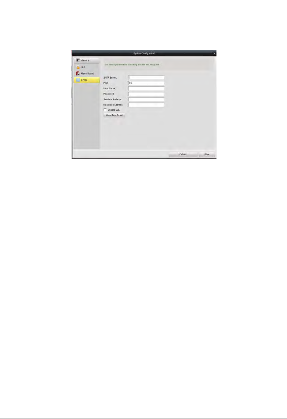
131
Client Software for PC or Mac
Email
The Email sub-menu allows you to configure outgoing email settings for the client
software. This allows you to send videos, pictures, or alert information using the client.
To configure client email settings:
NOTE: Contact your email service provider to determine the SMTP Server address, port, user
name, password, or security settings.
1Under SMTP Server, enter the address of your email server.
2Under Port, enter the SMTP Server port number.
3Under User Name and Password, enter the account name and password for the SMTP
Server.
4Under Sender’s Address, enter the address that will be used to send out email alerts.
5Under Receiver’s Address, enter the address that will receive email alerts.
6Check Enable SSL to enable secure authentication.
7Click Send Test Email to send a test email to the receiver’s address.
8Click Save to save changes.

132
Mobile Apps: Accessing your NVR Using a Mobile Device
Mobile Apps: Accessing your NVR Using a Mobile
Device
You can remotely view camera streams from your NVR on compatible mobile phones and
tablets.
Compatible Devices and Platforms
Platform Supported Versions and Devices App Name Get App From
iOS iOS v. 4.0 and higher
iPhone/iPod Touch
iPad (1st generation and above)
Lorex netHD Stratus
(iPhone)
Lorex netHD Stratus
Plus (iPad)
Apple App Store
Android Android v. 2.3 and above (phones) /
Android v. 3.2 and above (tablets)
Lorex netHD Stratus
(Android phones)
Lorex netHD Stratus
Plus (Android tablets)
Google Play Store
For the latest device compatibility list, visit www.lorextechnology.com
iPhone
Use the Lorex netHD Stratus application to connect to your NVR on the iPhone.
Prerequisites
• iOS version 4.0 and above.
• An iTunes account (requires valid credit card number). Your credit card will not be billed when
downloading the app.
• Connect your NVR to your router using an Ethernet cable (included).
• Make sure to upgrade your NVR to the latest firmware version. You must have the latest
NVR firmware and mobile apps to connect to the NVR over the Internet.
NOTE: For the latest device compatibility list, visit www.lorextechnology.com
Connecting to your NVR using an iPhone
1Download the free Lorex netHD Stratus app from the App Store.
2Touch the Lorex netHD Stratus icon ( ).
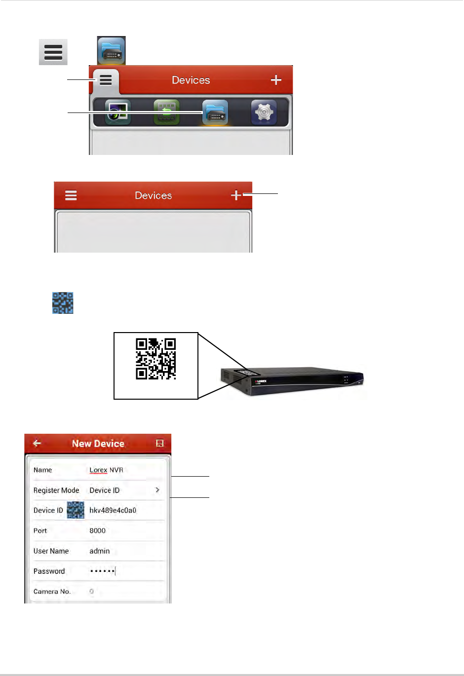
133
Mobile Apps: Accessing your NVR Using a Mobile Device
3Tap then .
Tap
Then, tap
4Touch +.
Touch +
5Under Name, enter a name for your NVR of your choice (e.g. home or office).
6Press next to Device ID and then line up the QR code on the top of the NVR with the
camera on your device.
Device ID:xxxxxxx
OR,
If your device does not have a camera, manually enter the Device ID printed on the label.
Enter a name for your NVR
Enter Domain Name/URL Request, followed by .lorexddns.net
NOTE: If you have changed the User Name, Password, or Client Port from the defaults, you will
need to update them.
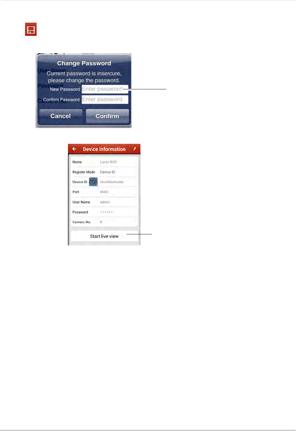
134
Mobile Apps: Accessing your NVR Using a Mobile Device
7Tap . You will be prompted to change the NVR password.
8Enter a new 6 character password for the NVR and then press Confirm.
Enter a new 6 character password
and then press Confirm
9Tap Start live view. The app opens the Live View screens and shows video from your cameras.
Tap to view your cameras
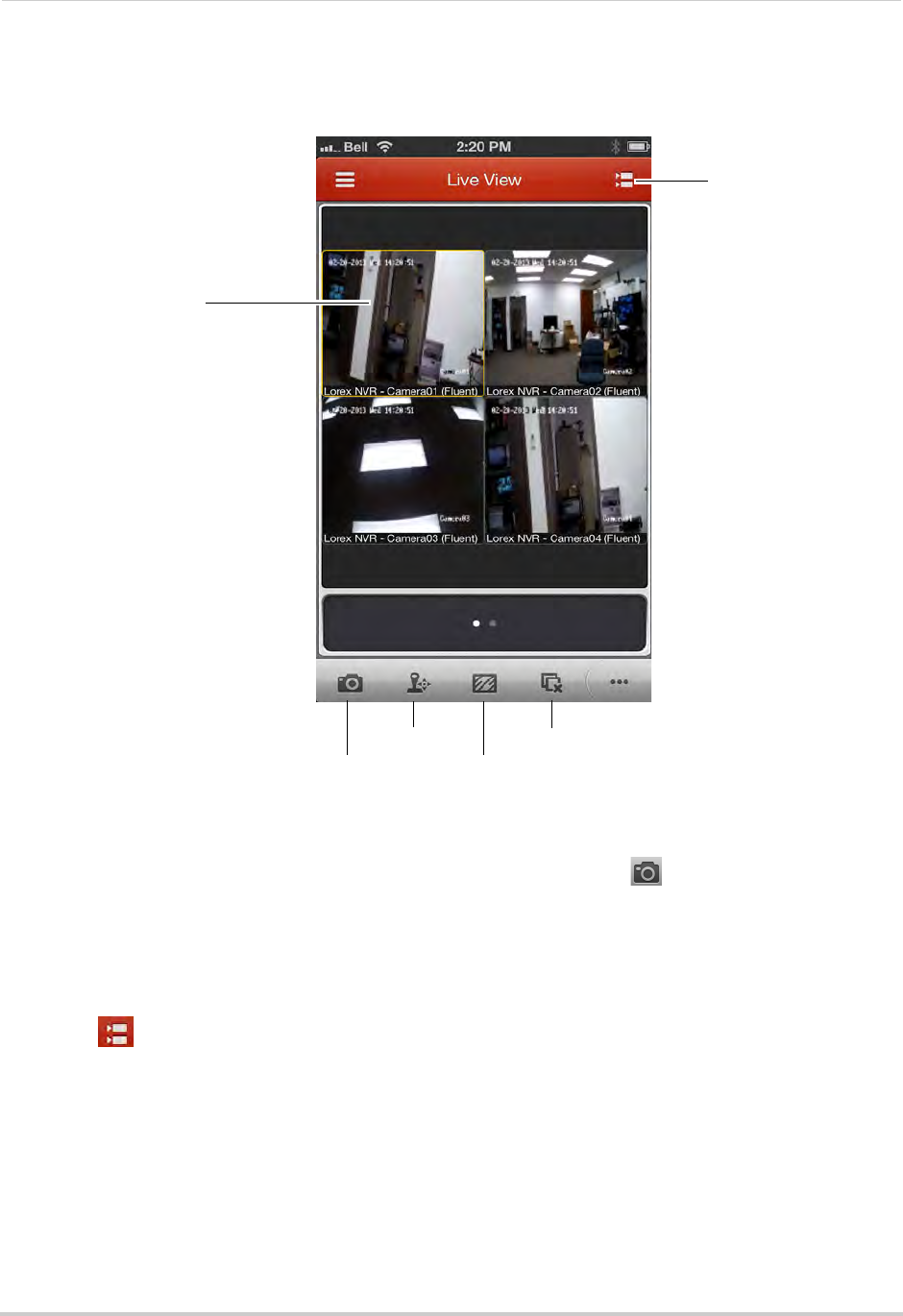
135
Mobile Apps: Accessing your NVR Using a Mobile Device
Live View Interface
You can use Live View in landscape or portrait mode.
Tap to select channels
Swipe to change pages
View/select cameras
Screenshot
Not supported
Image quality
Disconnect
Taking Screenshots
1Tap the camera you would like to take a screenshot of, then tap .
2Tap OK to allow the app to save photos on your device.
• You can access screenshots using the Photos app.
Switching Cameras
1Touch to access the Camera List.
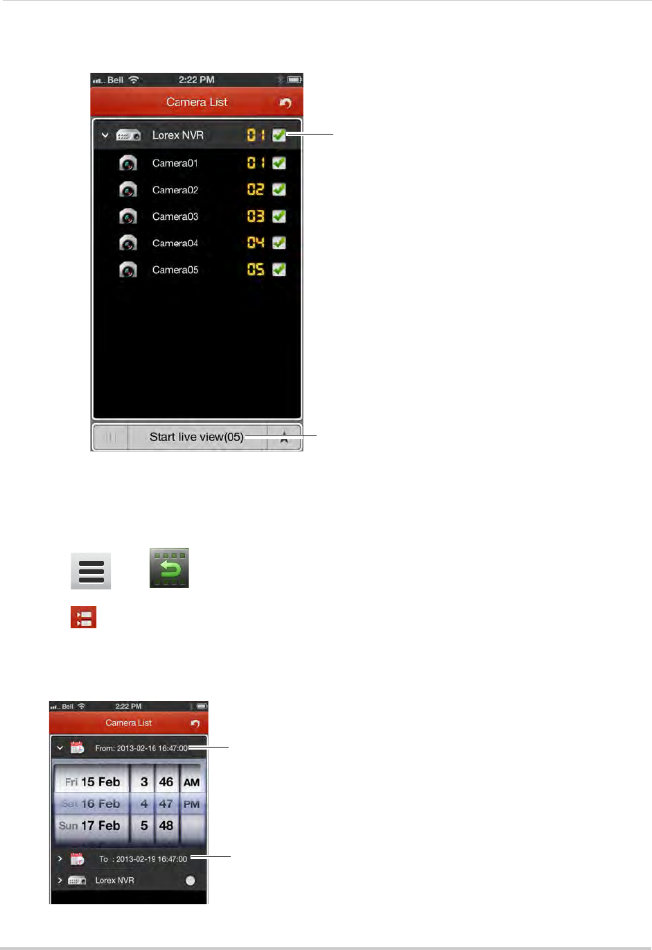
136
Mobile Apps: Accessing your NVR Using a Mobile Device
2Check the cameras you would like to view, then touch Start live view.
Check cameras
Touch Start live view
Playback
You can access video recorded on your NVR from your iPhone.
To access playback mode:
1Touch then .
2Touch to access the Camera List.
3Tap From and use the sliders to enter the start time for your search.
4Tap To and use the sliders to enter the end time for your search.
Tap From and enter the start time
for your search
Tap To and enter the end time for
your search
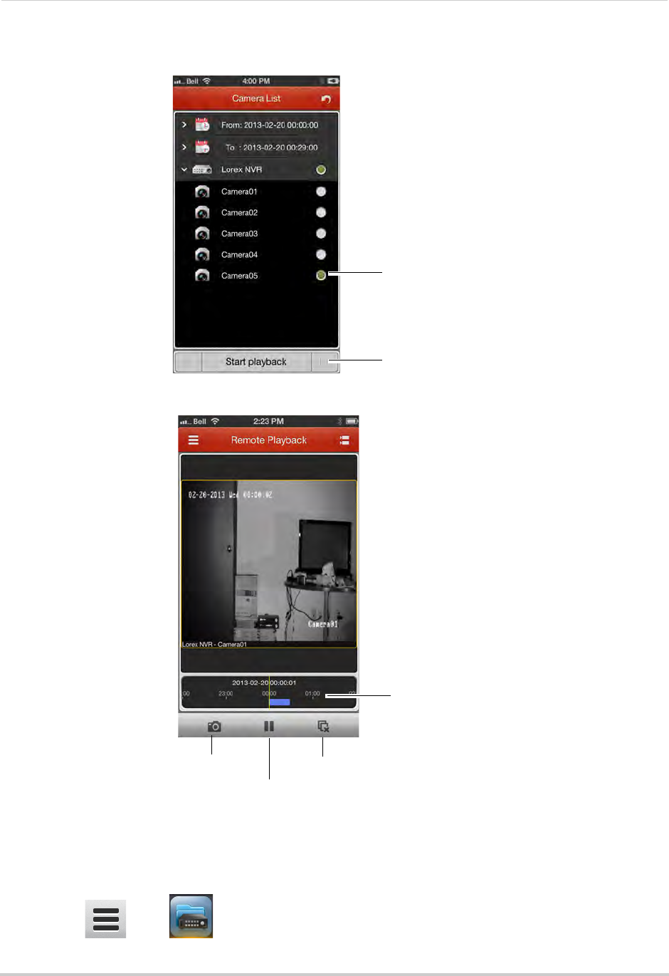
137
Mobile Apps: Accessing your NVR Using a Mobile Device
5Tap the camera you would like to playback video from, and then touch Start playback.
Tap the camera
Tap Start playback
6Use the on-screen controls.
Drag to change
playback time
Screenshot
Pause/play
Disconnect
Device List
The Device List allows you to modify or delete NVR connection details.
To access Device List:
• Touch then .
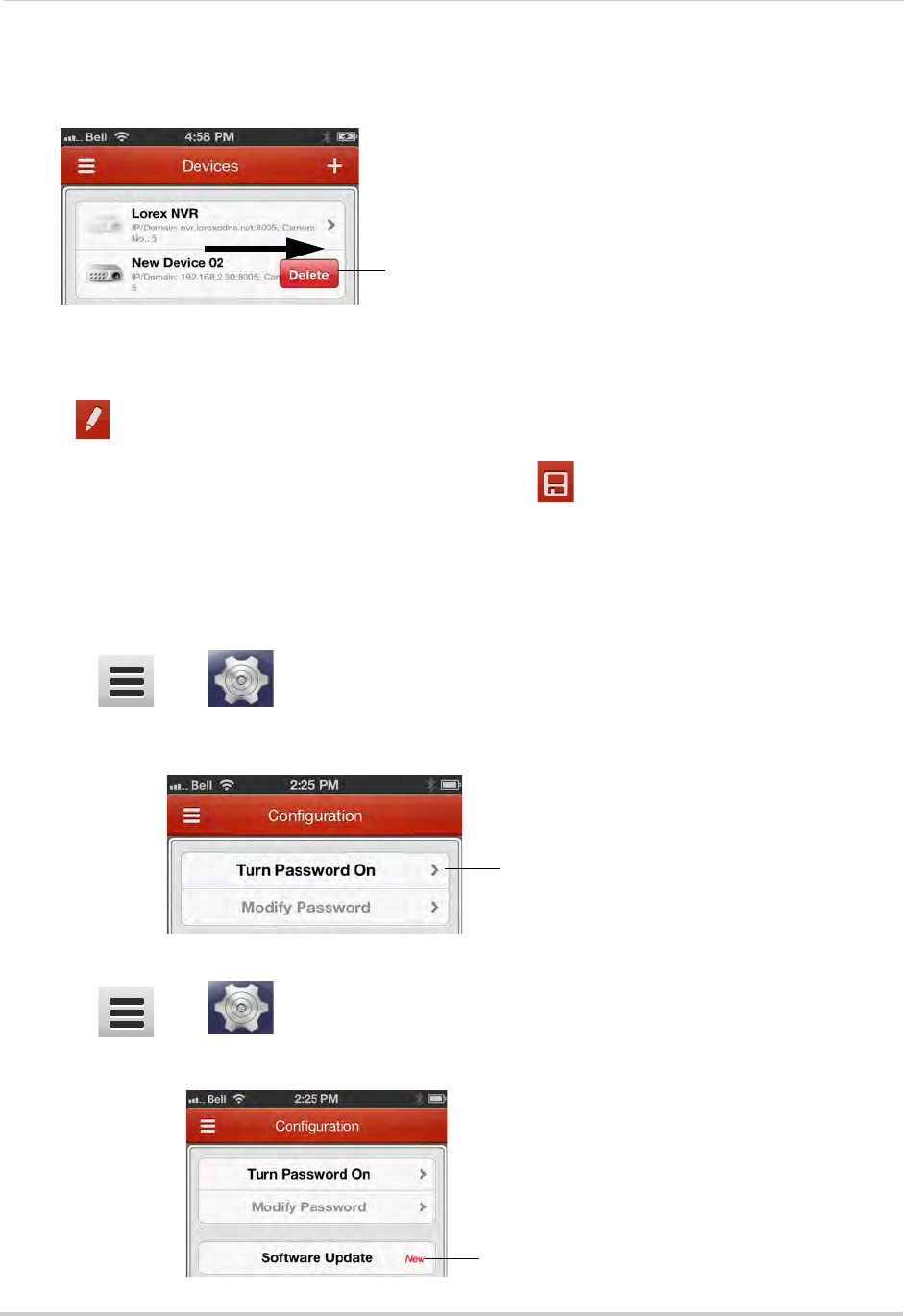
138
Mobile Apps: Accessing your NVR Using a Mobile Device
To delete an NVR:
• Swipe the NVR from the left, and then tap Delete.
Swipe from the left then tap Delete
To modify an NVR:
1Tap the NVR.
2Tap .
3Modify the connection details as needed and then tap .
Configuration
Use the Configuration menu to enable password protection for the app or check for
updates in the App store.
To enable passwords for the app:
1Touch then .
2Tap Turn Password On. Enter a password. The app will now ask for a password when you
open it.
Tap Turn Password On
To check for software updates:
1Touch then .
2Tap Software Update to go to the App Store and check for updates.
Tap Software Update
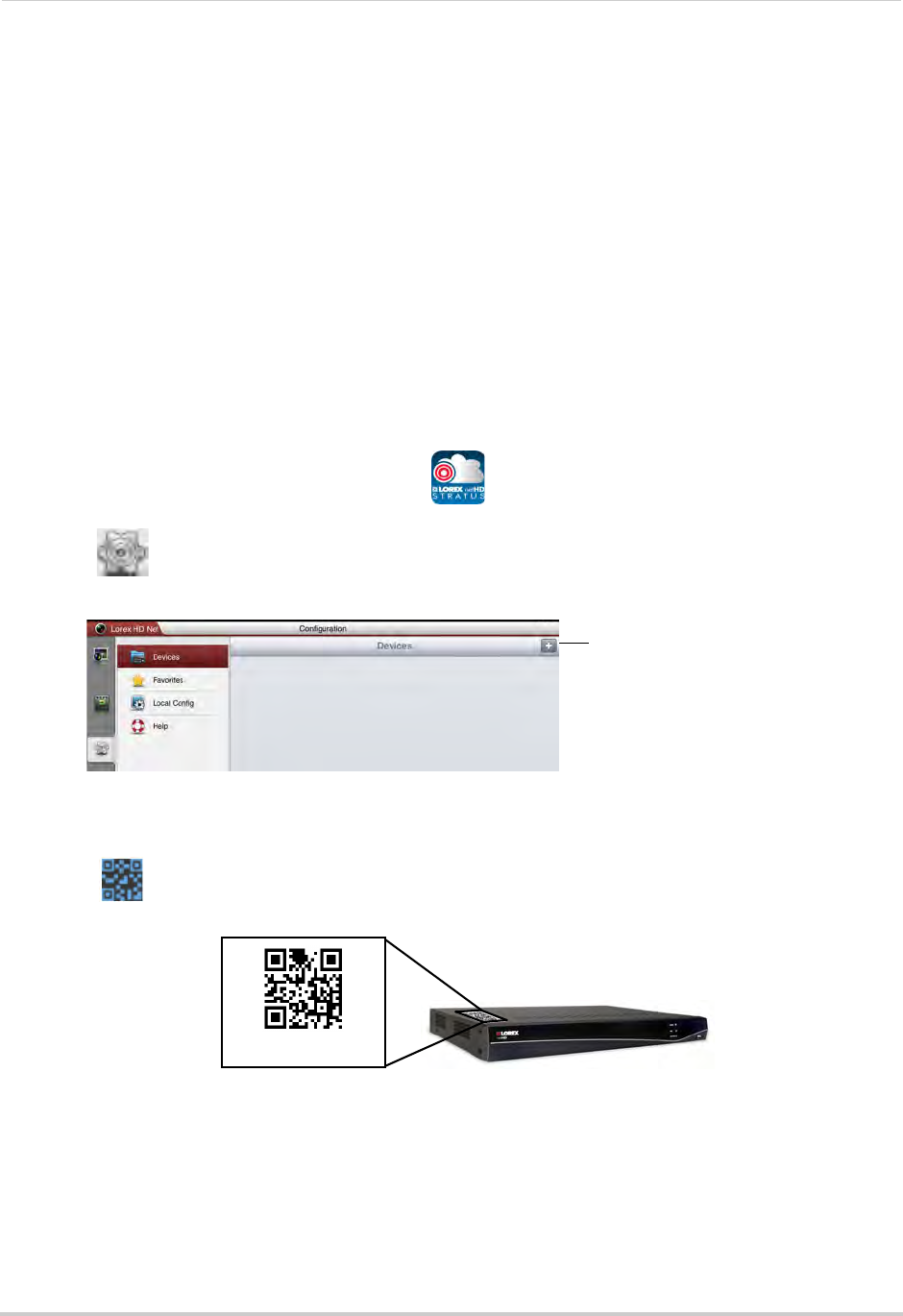
139
Mobile Apps: Accessing your NVR Using a Mobile Device
iPad
Use the Lorex netHD Stratus Plus application to connect to your NVR on the iPad.
Prerequisites
• iOS version 4.0 and above.
• An iTunes account (requires valid credit card number). Your credit card will not be billed when
downloading the app.
• Connect your NVR to your router using an Ethernet cable (included).
• Make sure to upgrade your NVR to the latest firmware version. You must have the latest
NVR firmware and mobile apps to connect to the NVR over the Internet.
NOTE: For the latest device compatibility list, visit www.lorextechnology.com
Connecting to your NVR using an iPad
1Download the free Lorex netHD Stratus Plus app from the App Store.
2Touch the Lorex netHD Stratus Plus icon ( ).
3Touch .
4Touch +.
Touch +
5Under Name, enter a name for your NVR of your choice (e.g. home or office).
6Press next to Device ID and then line up the QR code on the top of the NVR with the
camera on your device.
Device ID:xxxxxxx
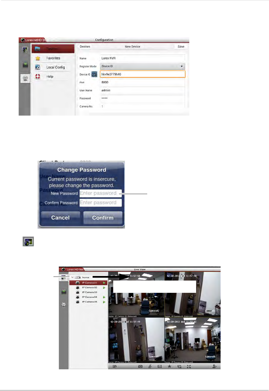
140
Mobile Apps: Accessing your NVR Using a Mobile Device
OR,
If your device does not have a camera, manually enter the Device ID printed on the label.
NOTE: If you have changed the User Name, Password, or Client Port from the defaults, you will
need to update them.
7Tap Save. You will be prompted to change the NVR password.
8Enter a new 6 character password for the NVR and then press Confirm.
Enter a new 6 character password
and then press Confirm
9Tap to go to Live View.
10 Press and drag the NVR to the viewing area to open all connected cameras, or drag individual
cameras to the viewing area to view them.
Drag the NVR or cameras to the
display area to open
Tap to view cameras
connected to the
NVR
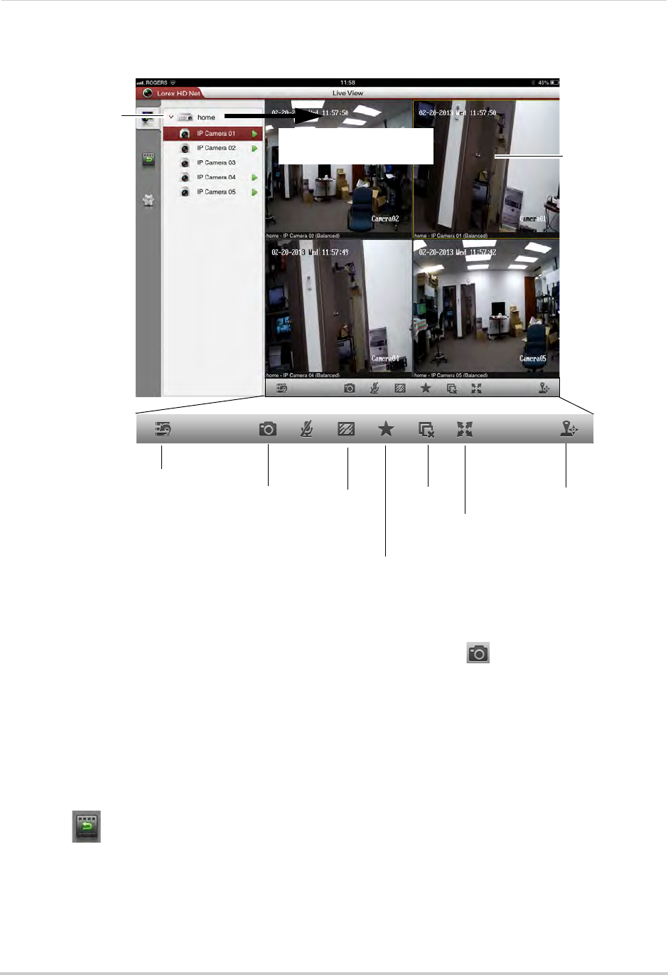
141
Mobile Apps: Accessing your NVR Using a Mobile Device
Live View Interface
Drag the NVR or cameras
to the display area to open
Tap to view cameras
connected to the NVR
Hide/show
device list Screenshot Image
quality
Add camera/view
to favorites
Full-screen
Not supported
Tap to select
camera, drag to
top to disconnect
Disconnect
all cameras
Taking Screenshots
1Tap the camera you would like to take a screenshot of, then tap .
2Tap OK to allow the app to save photos on your device.
• You can access screenshots using the Photos app.
Playback
You can view recorded video from your NVR on your iPad.
To access playback mode:
1Touch .
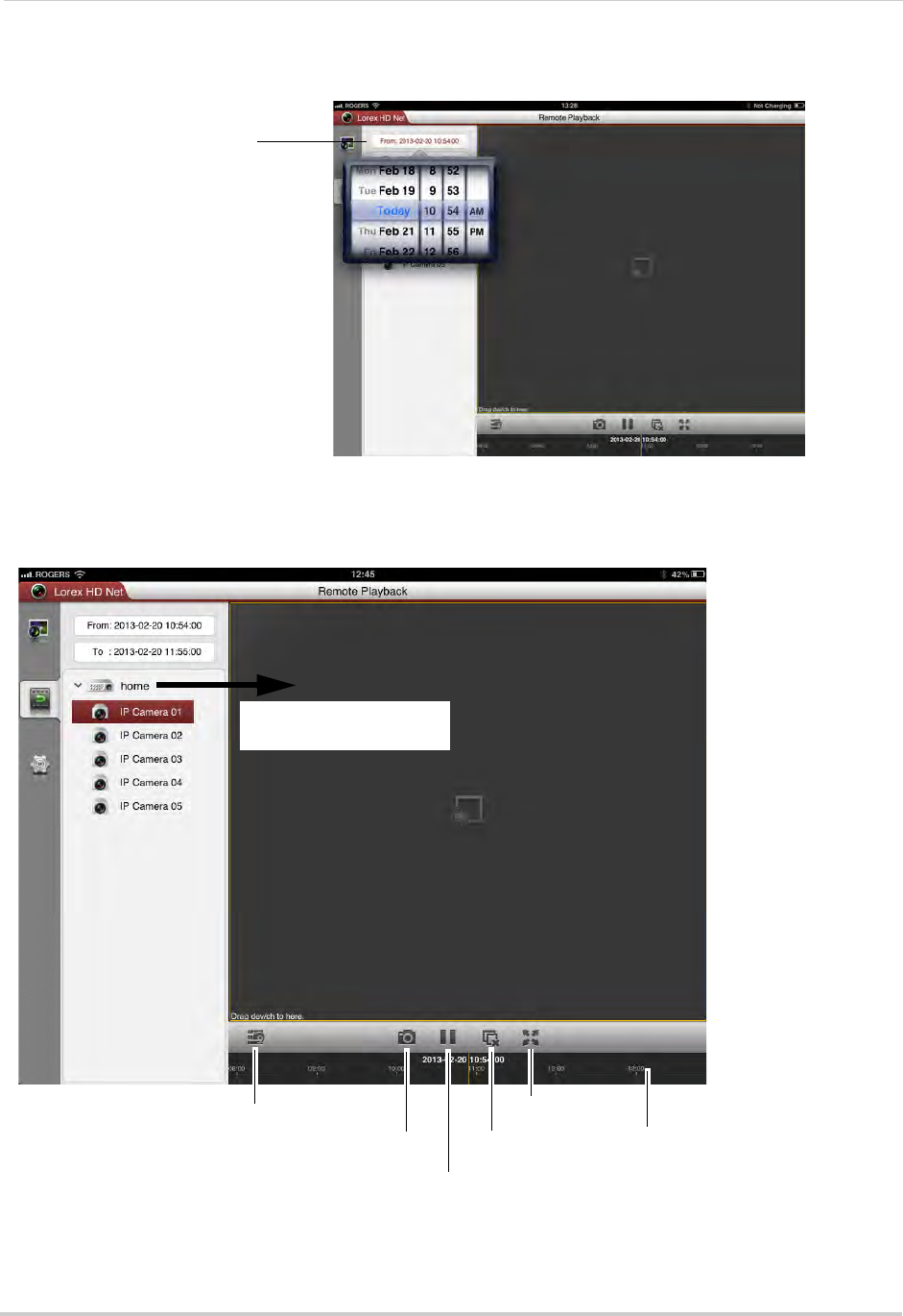
142
Mobile Apps: Accessing your NVR Using a Mobile Device
2Tap From and use the sliders to adjust the start time for your search.
Tap From and use
sliders to select the
start time
3Tap To and use the sliders to adjust the end time for your search.
4Drag the NVR or camera to the display area to start playback. Use the on-screen controls.
Drag the NVR or cameras
to the display area to open
Hide/show device list
Screenshot
Pause/play
Disconnect
Full-screen
Tap and drag in the bar to
select playback time
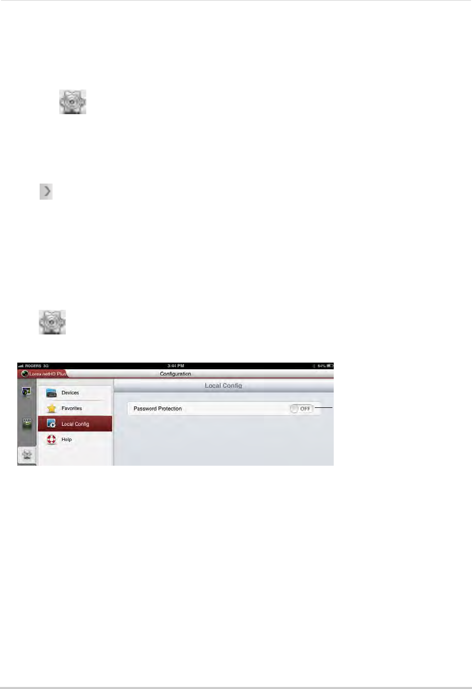
143
Mobile Apps: Accessing your NVR Using a Mobile Device
Device List
Use the Device List to manage your NVRs.
To access Device List:
• Touch .
Deleting NVRs
• Swipe the NVR you would like to delete from the left and tap Delete. Tap Confirm.
Modifying NVRs
1Tap next to the NVR you would like to edit.
2Tap Edit. Modify the connection details as needed.
3Tap Save to save changes.
Local Config
The Local Config menu allows you to enable passwords for the app.
To enable passwords for the app:
1Tap then tap Local Config.
2Slide Password Protection to ON.
Slide to ON to enable a password
to access the app
3Enter a password for the app and press Confirm. You will now be asked for your password
when you open the app.
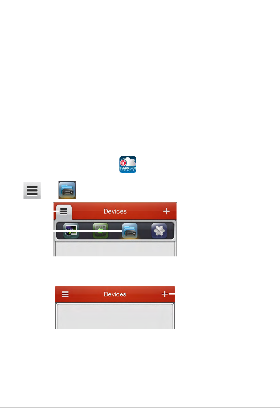
144
Mobile Apps: Accessing your NVR Using a Mobile Device
Android Phone
Use the Lorex netHD Stratus application to connect to your NVR on an Android
smartphone.
There is a separate app for Android tablets to make better use of the larger screen size.
For details, see “Android Tablet” on page 150.
NOTE: The instructions below may differ depending on the model of your Android device.
System requirements
• Android v. 2.3 and above.
NOTE: For the latest device compatibility list, visit www.lorextechnology.com
Connecting to your System Using an Android Phone
1Download the Lorex netHD Stratus app for free from the Google Play Store.
NOTE: For support on downloading or installing Android apps, consult your Android device’s
user’s manual or the manufacturer’s support site.
2Touch the Lorex netHD Stratus icon ( ).
3Tap then .
Tap
Then, tap
4Touch +.
Touch +
5Under Name, enter a name for your NVR of your choice (e.g. home or office).
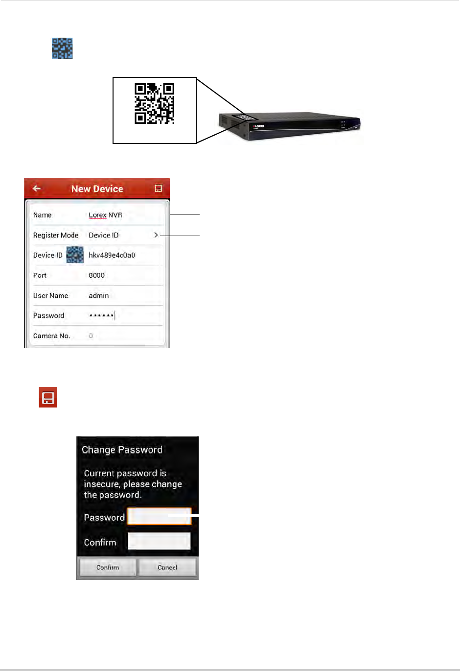
145
Mobile Apps: Accessing your NVR Using a Mobile Device
6Press next to Device ID and then line up the QR code on the top of the NVR with the
camera on your device.
Device ID:xxxxxxx
OR,
If your device does not have a camera, manually enter the Device ID printed on the label.
Enter a name for your NVR
Enter Domain Name/URL Request, followed by .lorexddns.net
NOTE: If you have changed the User Name, Password, or Client Port from the defaults, you will
need to update them.
7Tap . You will be prompted to change the NVR password.
8Enter a new 6 character password for the NVR and then press Confirm.
Enter a new 6 character password
and then press Confirm
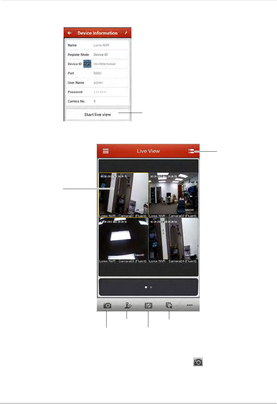
146
Mobile Apps: Accessing your NVR Using a Mobile Device
9Tap Start live view. The app opens the Live View screens and shows video from your cameras.
Tap to view your cameras
Live View Interface
You can use Live View in landscape or portrait mode.
Tap to select channels
Swipe to change pages
View/select cameras
Screenshot
Not supported
Image quality
Disconnect
Taking Screenshots
1Tap the camera you would like to take a screenshot of, then tap .
2Tap OK to allow the app to save photos on your device.
• Screenshots are saved to
/Lorex netHD/Picture
.
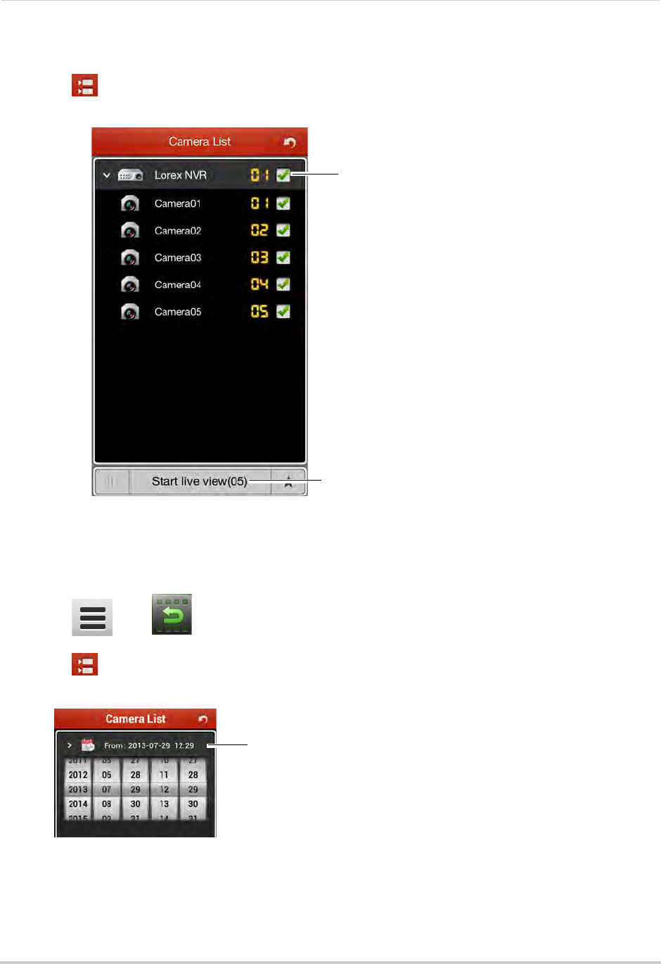
147
Mobile Apps: Accessing your NVR Using a Mobile Device
Switching Cameras
1Touch to access the Camera List.
2Check the cameras you would like to view, then touch Start live view.
Check cameras
Touch Start live view
Playback
You can access video recorded on your NVR from your phone.
To access playback mode:
1Touch then .
2Touch to access the Camera List.
3Tap From and use the sliders to enter the start time for your search.
Tap From and enter the start time
for your search
4Tap To and use the sliders to enter the end time for your search.
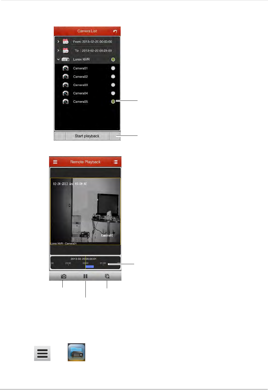
148
Mobile Apps: Accessing your NVR Using a Mobile Device
5Tap the camera you would like to playback video from, and then touch Start playback.
Tap the camera
Tap Start playback
6Use the on-screen controls.
Drag to change
playback time
Screenshot
Pause/play
Disconnect
Device List
The Device List allows you to modify or delete NVR connection details.
To access Device List:
• Touch then .
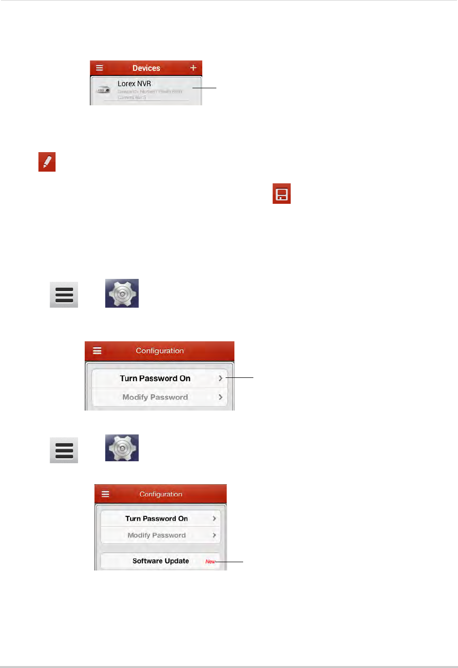
149
Mobile Apps: Accessing your NVR Using a Mobile Device
To delete an NVR:
• Tap and hold the NVR, and then tap Confirm.
Press and hold, and then tap Confirm
To modify an NVR:
1Tap the NVR.
2Tap .
3Modify the connection details as needed and then tap .
Configuration
Use the Configuration menu to enable password protection for the app or check for
updates in the App store.
To enable passwords for the app:
1Touch then .
2Tap Turn Password On. Enter a password. The app will now ask for a password when you
open it.
Tap Turn Password On
To check for software updates:
1Touch then .
2Tap Software Update to check for updates.
Tap Software Update
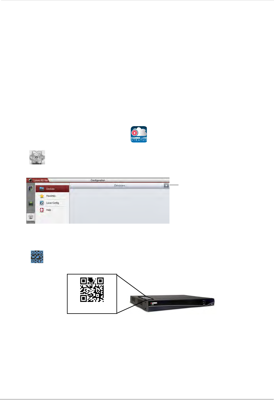
150
Mobile Apps: Accessing your NVR Using a Mobile Device
Android Tablet
Use the Lorex netHD Stratus Plus application to connect to your NVR on an Android tablet.
NOTE: The instructions below may differ depending on the model of your Android device.
System requirements
• Android v. 3.2 and above.
NOTE: For the latest device compatibility list, visit www.lorextechnology.com
Connecting to your System using an Android Tablet
1Download the Lorex netHD Stratus Plus app for free from the Google Play Store.
NOTE: For support on downloading or installing Android apps, consult your Android device’s
user’s manual or the manufacturer’s support site.
2Touch the Lorex netHD Stratus Plus icon ( ).
3Touch .
4Touch +.
Touch +
5Under Name, enter a name for your NVR of your choice (e.g. home or office).
6Press next to Device ID and then line up the QR code on the top of the NVR with the
camera on your device.
Device ID:xxxxxxx
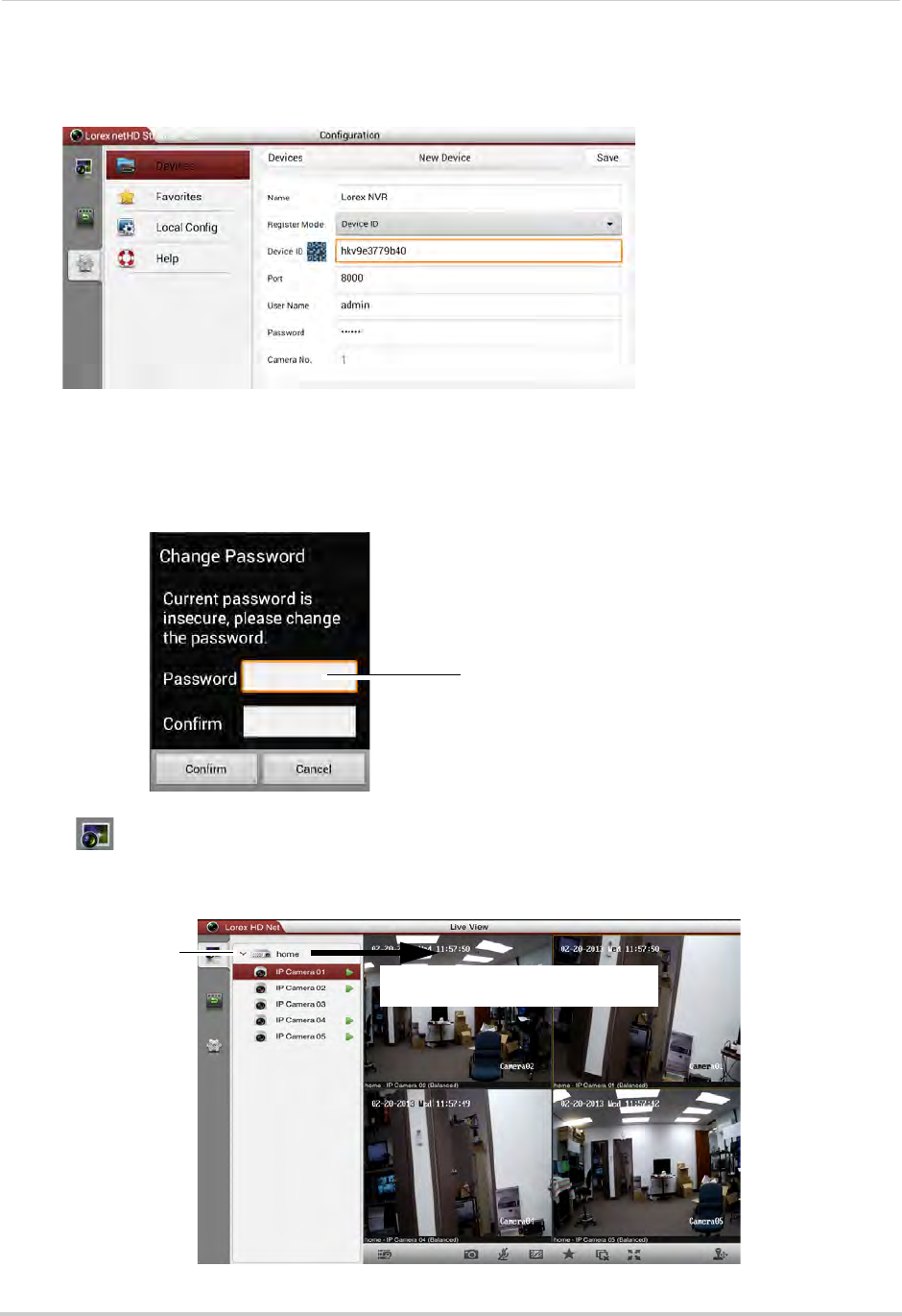
151
Mobile Apps: Accessing your NVR Using a Mobile Device
OR,
If your device does not have a camera, manually enter the Device ID printed on the label.
NOTE: If you have changed the User Name, Password, or Client Port from the defaults, you will
need to update them.
7Tap Save.You will be prompted to change the NVR password.
8Enter a new 6 character password for the NVR and then press Confirm.
Enter a new 6 character password
and then press Confirm
9Tap to go to Live View.
10 Press and drag the NVR to the viewing area to open all connected cameras, or drag individual
cameras to the viewing area to view them.
Drag the NVR or cameras to the
display area to open
Tap to view cameras
connected to the
NVR
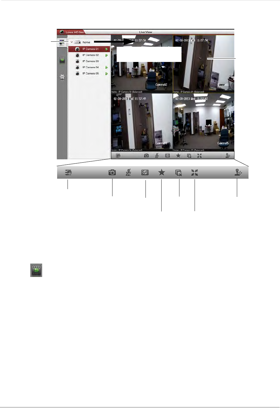
152
Mobile Apps: Accessing your NVR Using a Mobile Device
Live View
Drag the NVR or cameras
to the display area to open
Tap to view cameras
connected to the NVR
Hide/show
device list Screenshot Image
quality
Add camera/view
to favorites
Full-screen
Not supported
Tap to select
camera, drag to
top to disconnect
Disconnect
all cameras
Playback
You can playback video recorded on your NVR from your Android tablet.
To access playback mode:
1Touch .
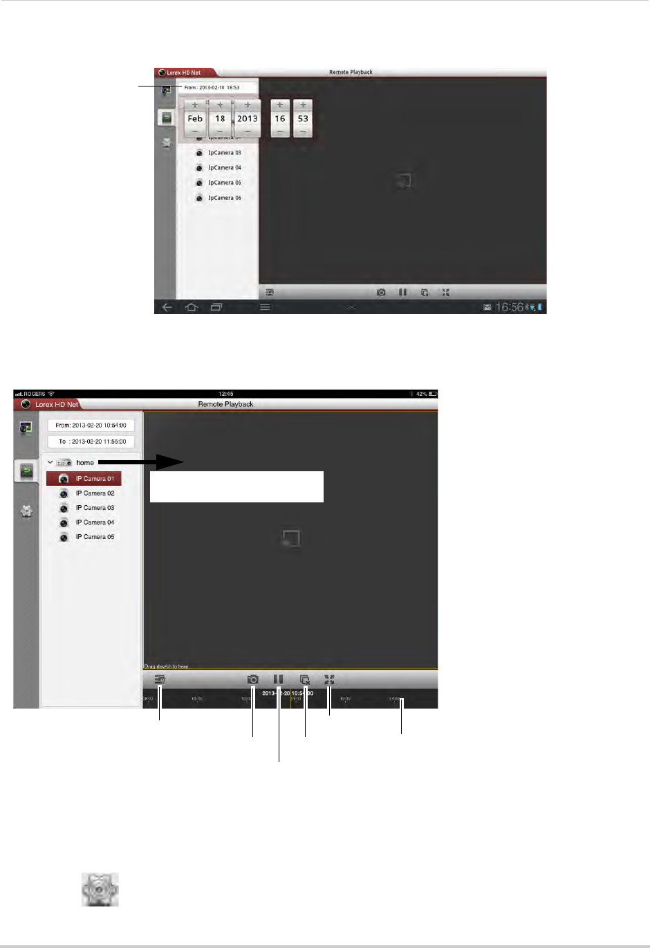
153
Mobile Apps: Accessing your NVR Using a Mobile Device
2Tap From and press + and - to adjust the start time for your search.
Tap From and select
the start time
3Tap To and use the sliders to adjust the end time for your search.
4Drag the NVR or camera to the display area to start playback. Use the on-screen controls.
Drag the NVR or cameras to
the display area to open
Hide/show device list
Screenshot
Pause/play
Disconnect
Full-screen
Tap and drag in the bar
to select playback time
Device List
Use the Device List to manage your NVRs.
To access Device List:
• Touch .
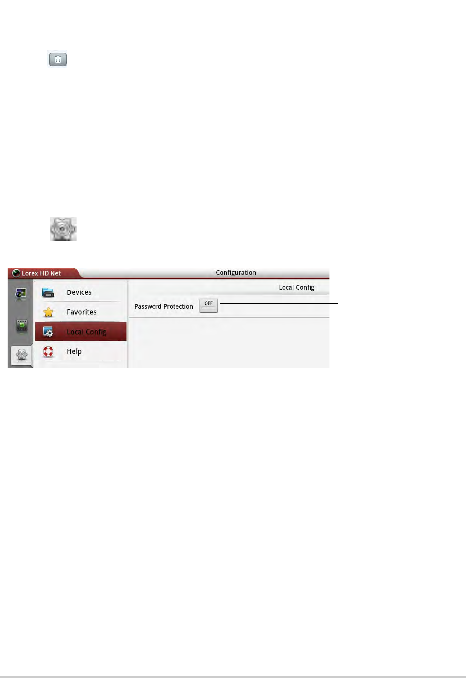
154
Mobile Apps: Accessing your NVR Using a Mobile Device
Deleting NVRs
• Tap next to the NVR you would like to delete. Tap Confirm.
Modifying NVRs
1Tap the NVR you would like to edit.
2Tap Edit. Modify the connection details as needed.
3Tap Save to save changes.
Local Config
The Local Config menu allows you to enable passwords for the app.
To enable passwords:
1Touch then Local Config.
2Tap the button next to Password Protection.
Press to enable a password
to access the app
3Enter a password and press Confirm. The app will now ask for a password when it opens.
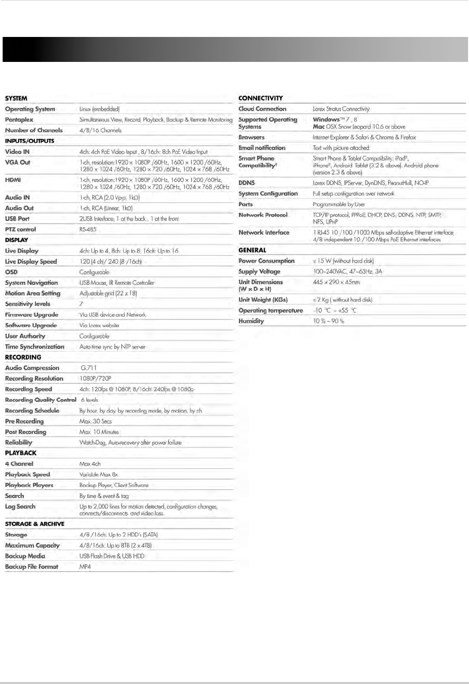
155
Appendix A: System Specifications
Appendix A: System Specifications
As our products are subject to continuous improvement, Lorex Technology Inc. and its
subsidiaries reserve the right to modify product design, specifications, and prices without
notice and without incurring any obligation.
E&OE
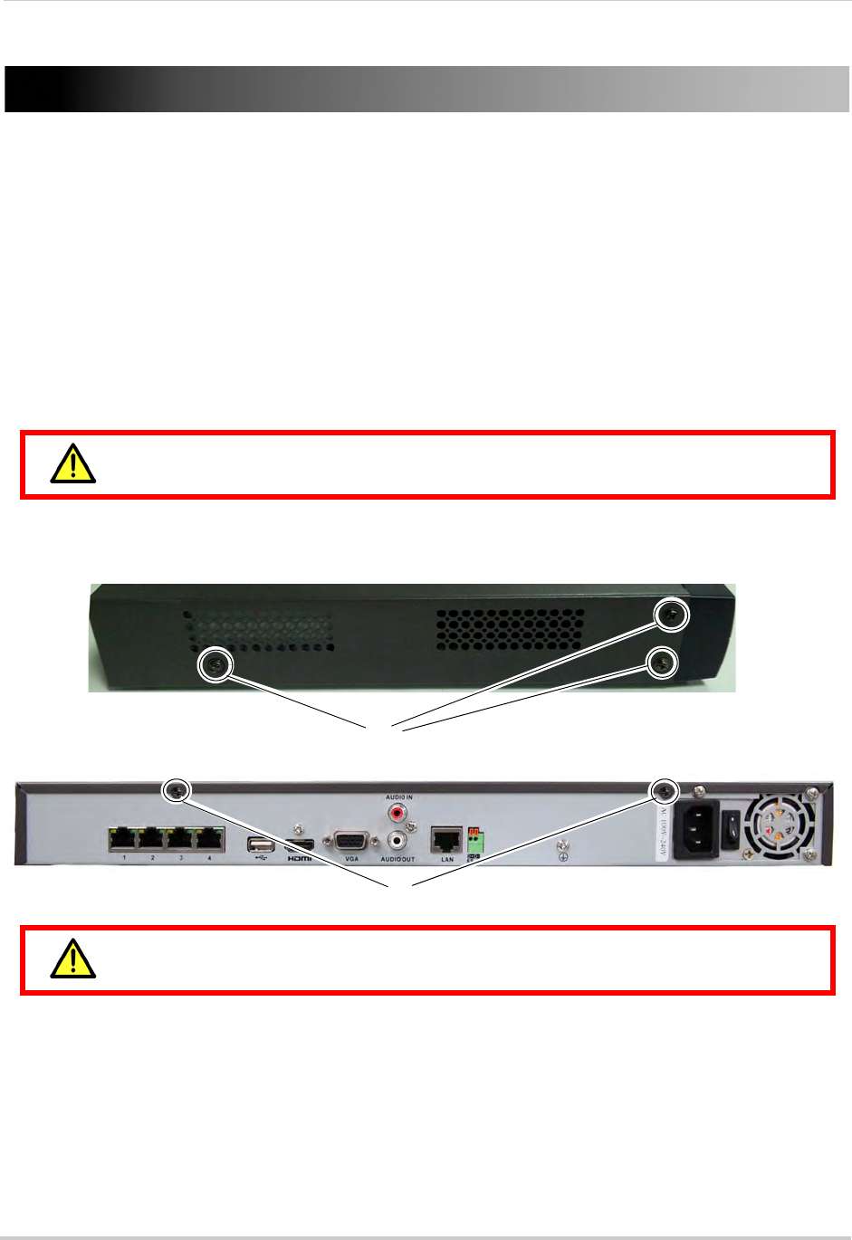
156
Appendix B: Installing or Replacing the Hard Drive
Appendix B: Installing or Replacing the Hard
Drive
The system comes with a pre-installed 3.5" SATA hard drive. You can expand the system
with up to two hard drives with a maximum capacity of 4TB each (for a maximum storage
space of 8TB).
NOTE: It is recommended to use surveillance or security-certified hard drives, which are
designed to be reliable over long periods of time while recording 24/7. Security-certified
hard drives are available at www.lorextechnology.com
Installing the Hard Drive
Make sure that the power cable has been disconnected before changing the
hard drive.
To install a hard drive:
1Remove the screws from each side panel (x3) and the top of the rear panel (x2) of the cover.
Side panel screws
Rear panel screws
Do not remove the other screws on the rear panel.
2Gently slide the cover away from the rear panel and lift off. Be careful of sharp edges.
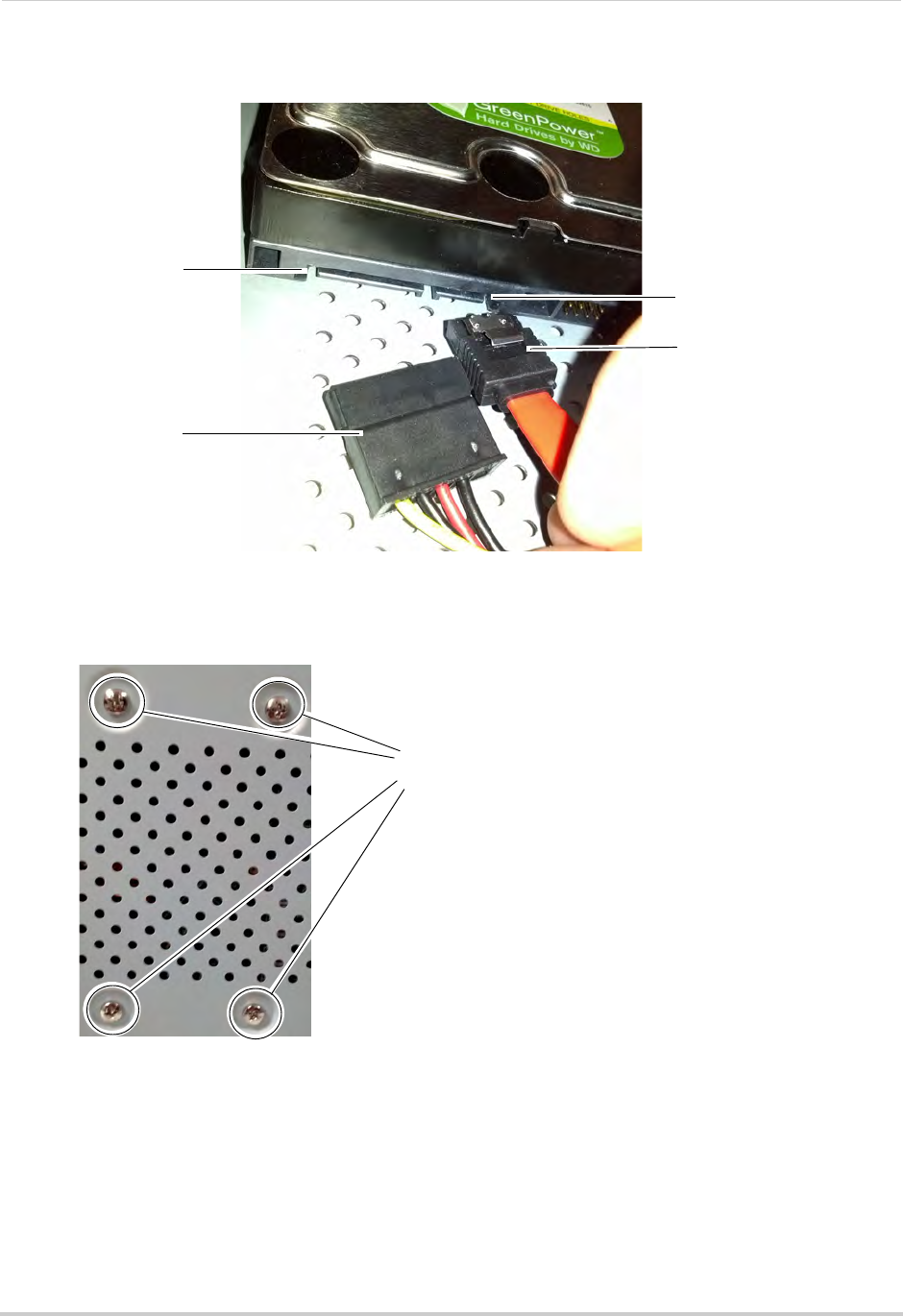
157
Appendix B: Installing or Replacing the Hard Drive
3Connect the power and data cables to the hard drive.
Hard drive data port
Data cable
Hard drive power
connector
Power cable
4Turn the NVR over and insert 4 screws to secure the hard drive. Make sure to hold the hard
drive in place while turning the NVR to avoid damaging the NVR.
Insert 4 screws to the bottom
panel to secure the hard drive
5Turn the NVR back over and replace the cover. Replace the side panel and rear panel screws.
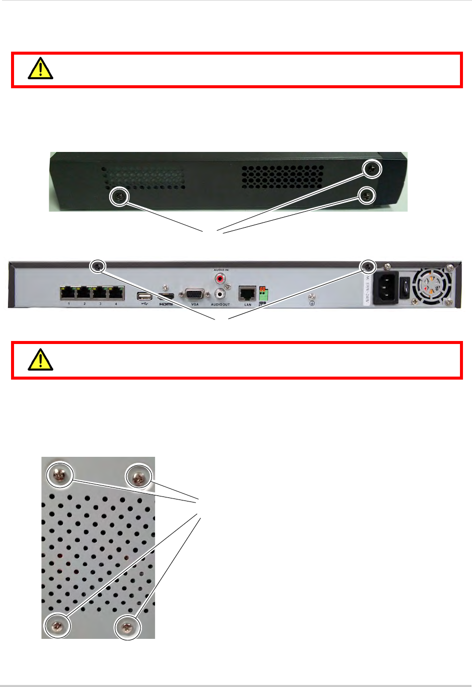
158
Appendix B: Installing or Replacing the Hard Drive
Removing the Hard Drive
Make sure that the power cable has been disconnected before changing the
hard drive.
To remove the hard drive:
1Remove the screws from the back (x2) and side panels.
2Remove the screws from each side panel (x3) and the top of the rear panel (x2) of the cover.
Side panel screws
Rear panel screws
Do not remove the other screws on the rear panel.
3Disconnect the power and data cables from the hard drive.
4Turn the NVR over and remove the 4 hard drive screws. Remove the hard drive from the
system. Make sure to hold the hard drive in place while removing the screws to avoid
damaging the NVR.
Remove the screws to
remove the hard drive
5Turn the NVR back over and replace the cover. Replace the side panel and rear panel screws.
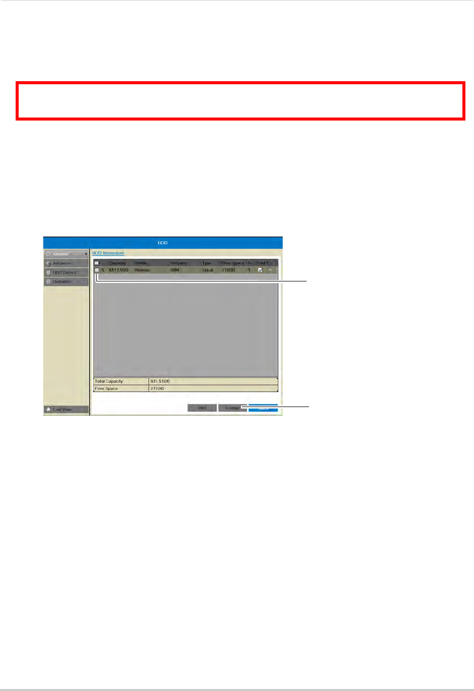
159
Appendix B: Installing or Replacing the Hard Drive
Formatting the Hard Drive
If you replace the pre-installed hard drive or install a new hard drive, it
must
be formatted
in order to function properly with the system.
ATTENTION: Formatting the HDD erases all data on the hard disk.
This step cannot be undone.
To format the hard disk:
1Right-click and then click Menu.
2Enter the system user name (default: admin) and password (default: 000000) and click Yes.
3Click HDD>General.
4Check the hard drive that you would like to format.
Check the hard
drive
Click Format
5Click Format. Click OK to confirm. Wait for the formatting to complete. Right-click repeatedly
to return to live view.
NOTE: You will notice that the size of the HDD and the free space are not the same. The system
uses a portion of the disk space for the operating system and initialization. This is
common in all security NVRs as well as computer hard drives.
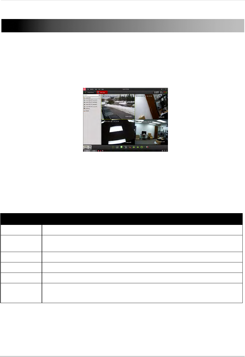
160
Appendix C: DDNS Setup (Advanced)
Appendix C: DDNS Setup (Advanced)
Free Lorex DDNS service is available as an optional connectivity method to connect to your
system over the Internet. DDNS Service is not required to connect to your NVR, since the
system supports the new Lorex Stratus cloud connectivity solution. For details on setting
up your system using Lorex Stratus, see “Connecting to Your NVR Over the Internet on PC
or Mac” on page 83.
Client Software for PC
For details on navigating the client software,
see “Client Software for PC or Mac” on page 87.
System Requirements
Prior to using Lorex Client Software, make sure your system meets or exceeds the
following system requirements:
Description Requirement
CPU Core 2 Duo 3.0GHz
Operating
System
Windows™ 8/7/Vista
Memory 2GB
Video 512 MB of video memory and above
Network (LAN) 10/100 BaseT Network
Network (WAN) 1 Mbps upstream
High-speed Internet service is required to remotely connect to your system.
NOTE: If a user connects to the system remotely, there may be slow performance when
accessing the system locally. This is normal, and not a malfunction.
For the latest compatibility list, check www.lorextechnology.com, as new software versions are released to
the market.
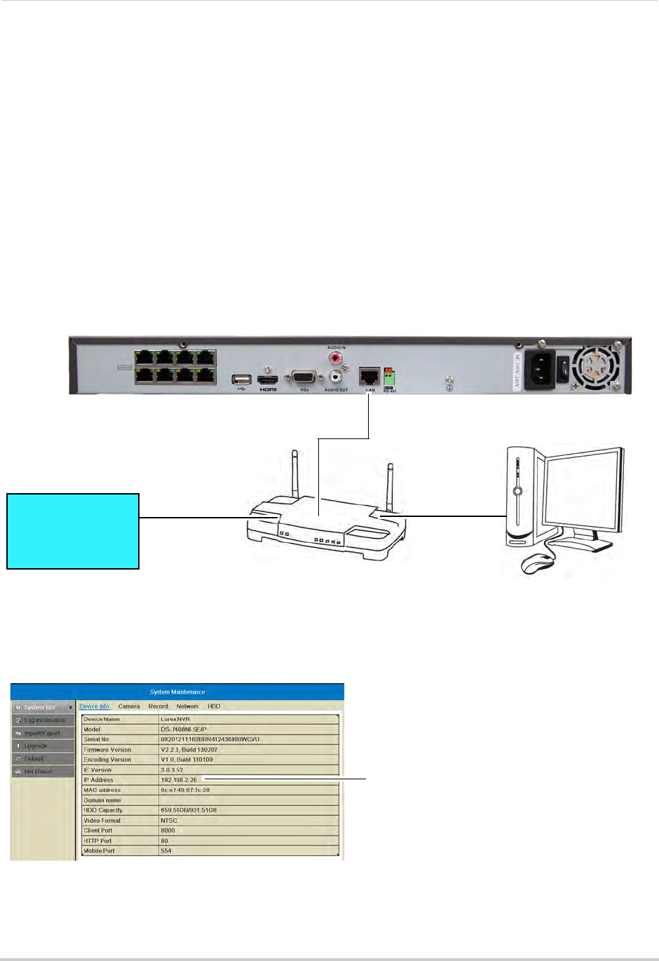
161
Appendix C: DDNS Setup (Advanced)
Accessing your NVR within a local network (LAN)
You can connect to your NVR on the local area network (LAN). It is recommended to
confirm connectivity over a local network before setting up your NVR for Internet
connectivity.
NOTE: To complete the steps below, your computer must be on the same network as your NVR.
Step 1 of 3: Connect your NVR to the Local Area Network
1Power off your NVR by turning the power switch to .
2Connect an Ethernet cable (included) to the LAN port on the rear panel of the NVR. Connect
the other end of the Ethernet cable to an empty LAN port (usually numbered 1~4) on your
router.
3Turn the power switch to I to power the NVR back on.
ROUTER
(Not Included)
COMPUTER
(Not Included)
(not required for
local viewing)
INTERNET
Ethernet Cable (included)
8-channel model shown
Step 2 of 3: Obtain the NVR’s Local IP Address
1Right-click and select Information to open the System Information window.
NVR IP address
2Write down the IP Address.
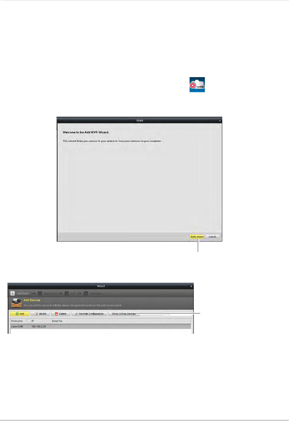
162
Appendix C: DDNS Setup (Advanced)
Step 3 of 3: Connect to the NVR on the Local Area Network
Follow the steps below to confirm connectivity over a local network on a PC.
To connect to the NVR on the LAN using a PC:
1Install the Client Software for PC from the CD or download the client software for free from
www.lorextechnology.com.
2Double-click the Lorex netHD Client icon from the desktop ( ). The client software opens
to the Add NVR Wizard.
3Click Enter Wizard.
Click Enter Wizard
4Click Show Online Devices. The client software scans for NVRs on your network.
Show Online Devices
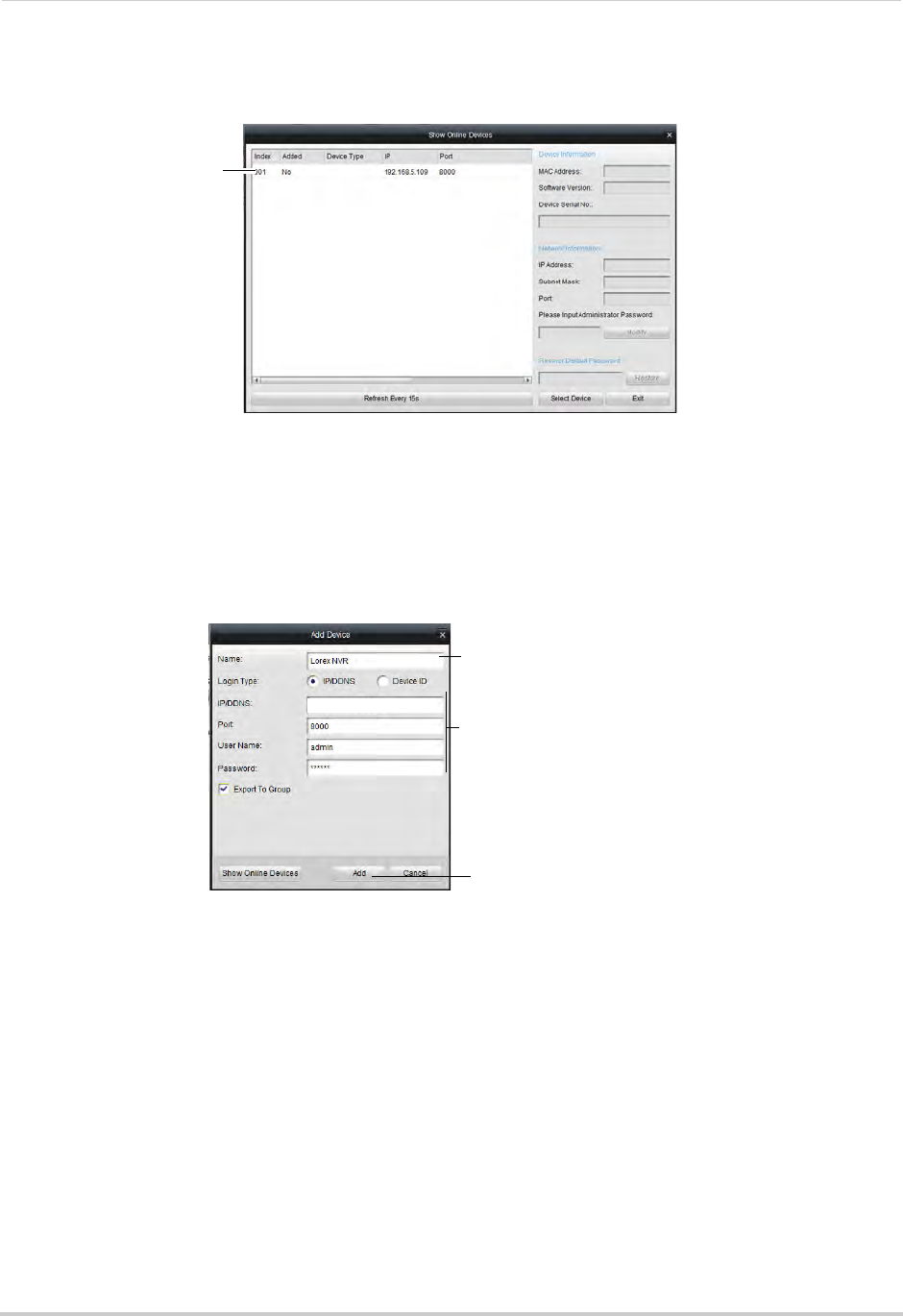
163
Appendix C: DDNS Setup (Advanced)
5Double-click your NVR in the list and click Yes. The Add Device screen opens and populates
the NVR’s IP Address, Port, User Name, and Password.
Double-click your NVR in
the list and click Yes
NOTE: If you have changed the User Name, Password, you must enter your new User Name
and Password.
NOTE: If your NVR does not appear in the list, click Exit>Add. Then enter the IP Address you
recorded previously under IP/DDNS and go to step 6.
6Under Nickname, enter a name for your NVR of your choice (e.g. home, business, etc.).
7Click Add.
192.168.5.121
Enter a name for your NVR
Automatically populated
Click Add
8If this is the first time connecting to your system, you will be prompted to change the
password. Enter a custom 6 character password and then click Yes.
9Click Next 3 times, then click Finished to complete the Wizard. The Client Software opens to
Main View and streams live video from your cameras.
Accessing your NVR Remotely over the Internet
Setting up remote connectivity allows you to view your NVR from any computer or
compatible mobile device with Internet access.
To set up remote connectivity with your NVR, you must:
1Port forward the HTTP, Client, and Mobile ports (default: 80, 8000, and 1025) on your router
to your NVR’s IP address.
2Create a DDNS account.
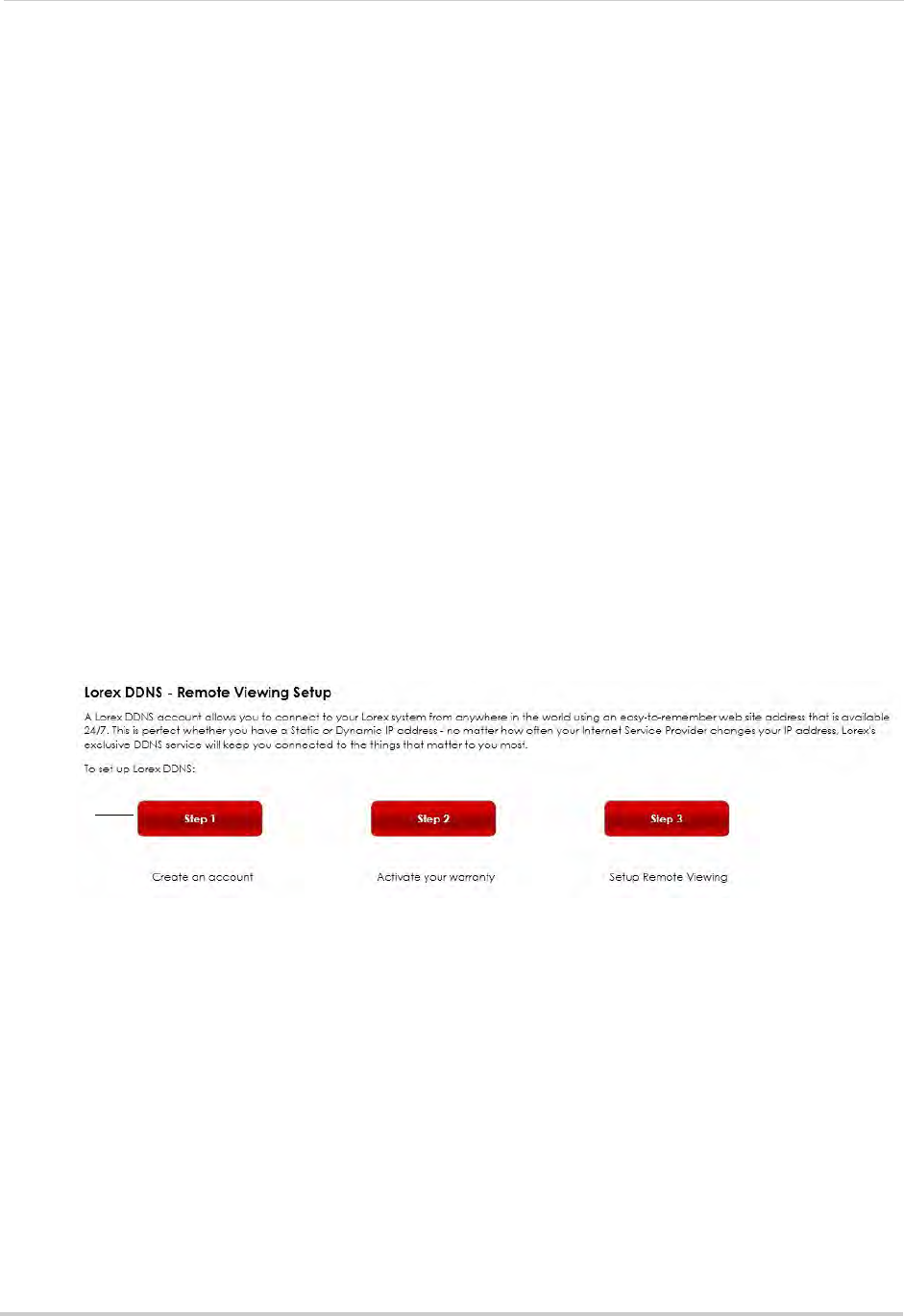
164
Appendix C: DDNS Setup (Advanced)
3Enable DDNS on the NVR.
4Test the remote connection by connecting to the NVR’s DDNS address.
Step 1 of 4: Port Forwarding
You must port forward the HTTP, Client, and Mobile ports (default: 80, 8000, and 1025) on
your router to your NVR’s IP address before you can remotely connect to your system.
There are several methods to port forward your router:
• Use the Lorex Easy Connect Auto Port Forwarding Wizard (PC only) to port forward the
required ports (see www.lorextechnology.com for details).
• Manually port forward the required ports on your router to your NVR’s IP address by
following your router manufacturer’s instructions. For more information on port
forwarding, see the reference guides on www.lorextechnology.com.
NOTE: If the above ports are not forwarded on your router, you will not be able to access your
system remotely.
Step 2 of 4: Create a DDNS Account
Lorex offers a free DDNS service for use with your system. A DDNS account allows you to
set up a web site address that points back to your local network. This allows you to connect
to your system remotely. You must create a DDNS account in the same network as your
NVR.
To setup your free Lorex DDNS account:
1In your browser, go to http://www.lorexddns.net and click Step 1.
Click Step 1
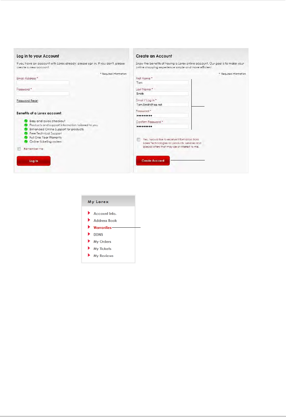
165
Appendix C: DDNS Setup (Advanced)
2The My Lorex account login screen opens (if you are already logged in, skip to step 4). Create
a new account or log into an existing account. To create a new account, fill in the required
fields on the right and click Create Account.
Enter your account Information
and click Create Account
Click Create Account
3Click Warranties to register your product for warranty.
Click Warranties
NOTE: Warranty registration is required to register for DDNS.
4The Warranty page opens. Click Activate Warranty to register your product for warranty.
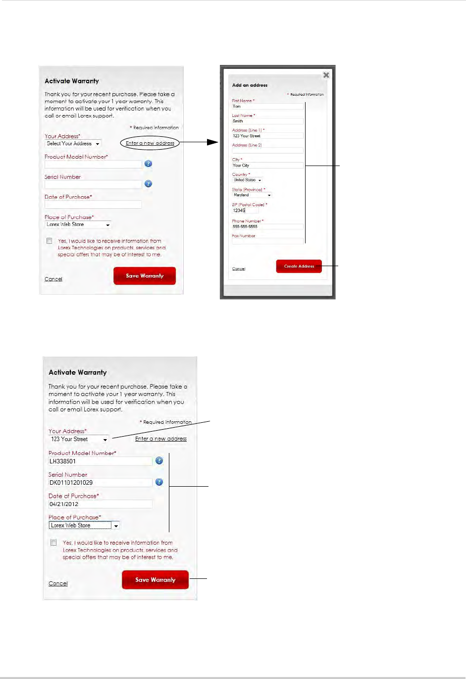
166
Appendix C: DDNS Setup (Advanced)
5Under Your Address, select an address or click Enter a New Address to create a new address.
Fill in your address information and click Create Address.
Enter your address
information
Click Create Address
6Fill in the warranty registration form with your product and purchase details. Check the
sticker underneath your NVR for the Product Model Number and Serial Number. Click Save
Warranty.
Select your address or
enter a new address
Enter your product and
purchase details
Click Save Warranty
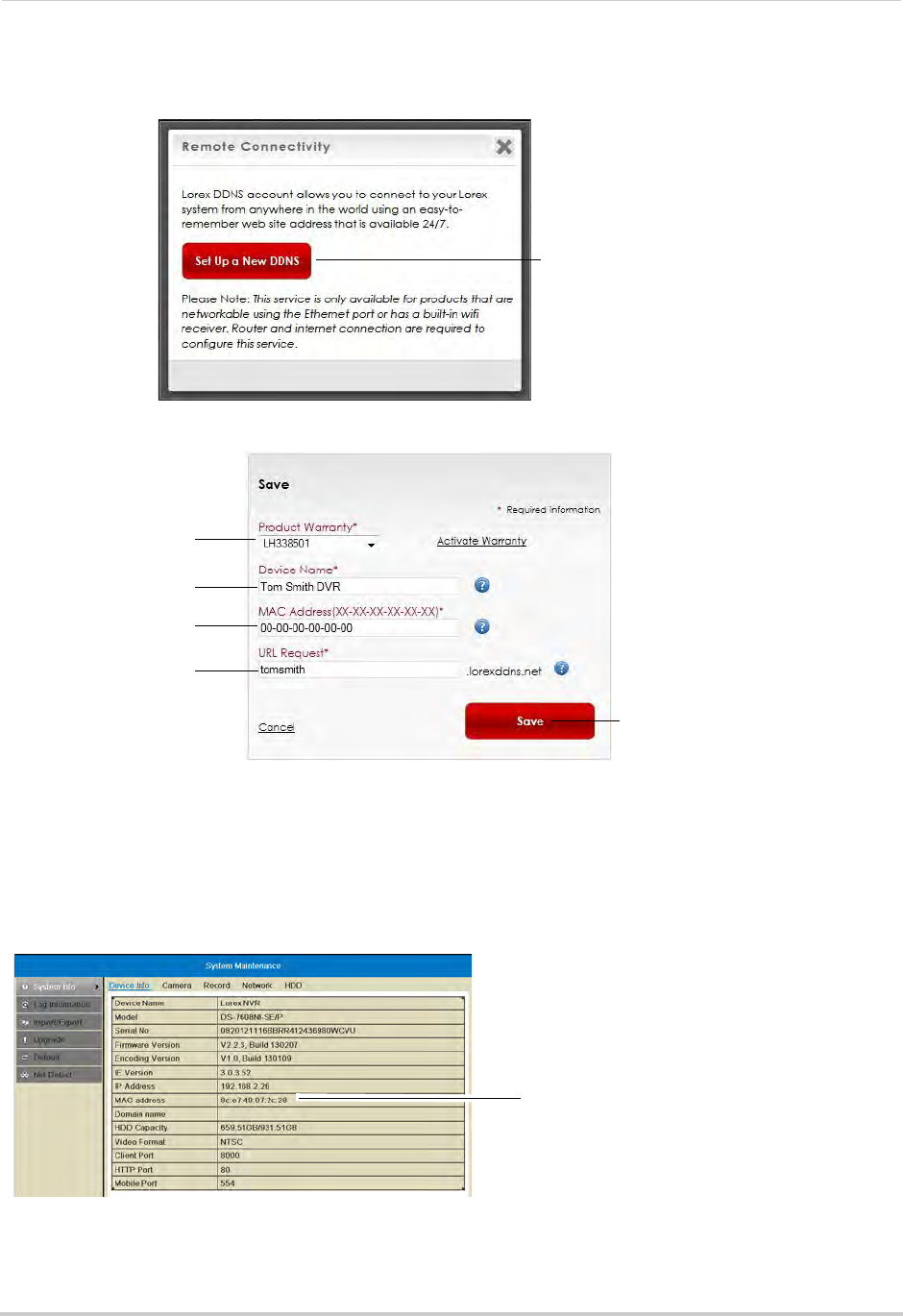
167
Appendix C: DDNS Setup (Advanced)
7A page pops up to prompt you to register your product for Lorex DDNS. Click Set Up a New
DDNS.
Click Set Up a New DDNS
8Configure the following:
Select your product
warranty
Enter a Device Name
of your choice
Enter the product’s
MAC address
Enter the web site
address that will be
used to connect
Click Save
• Product Warranty: Select the product warranty you created in the previous steps.
• Device Name: Enter a name for your device. You can enter your name, business name, or
anything of your choice. This is used to identify this device in your list of activated DDNS
accounts that appears anytime you visit the DDNS page.
• MAC Address: Enter the MAC address of your Lorex product. Right-click and select
Information to find your MAC address. A MAC address is a permanent, unique 12-digit address
used to identify a device on a network.
NVR MAC address
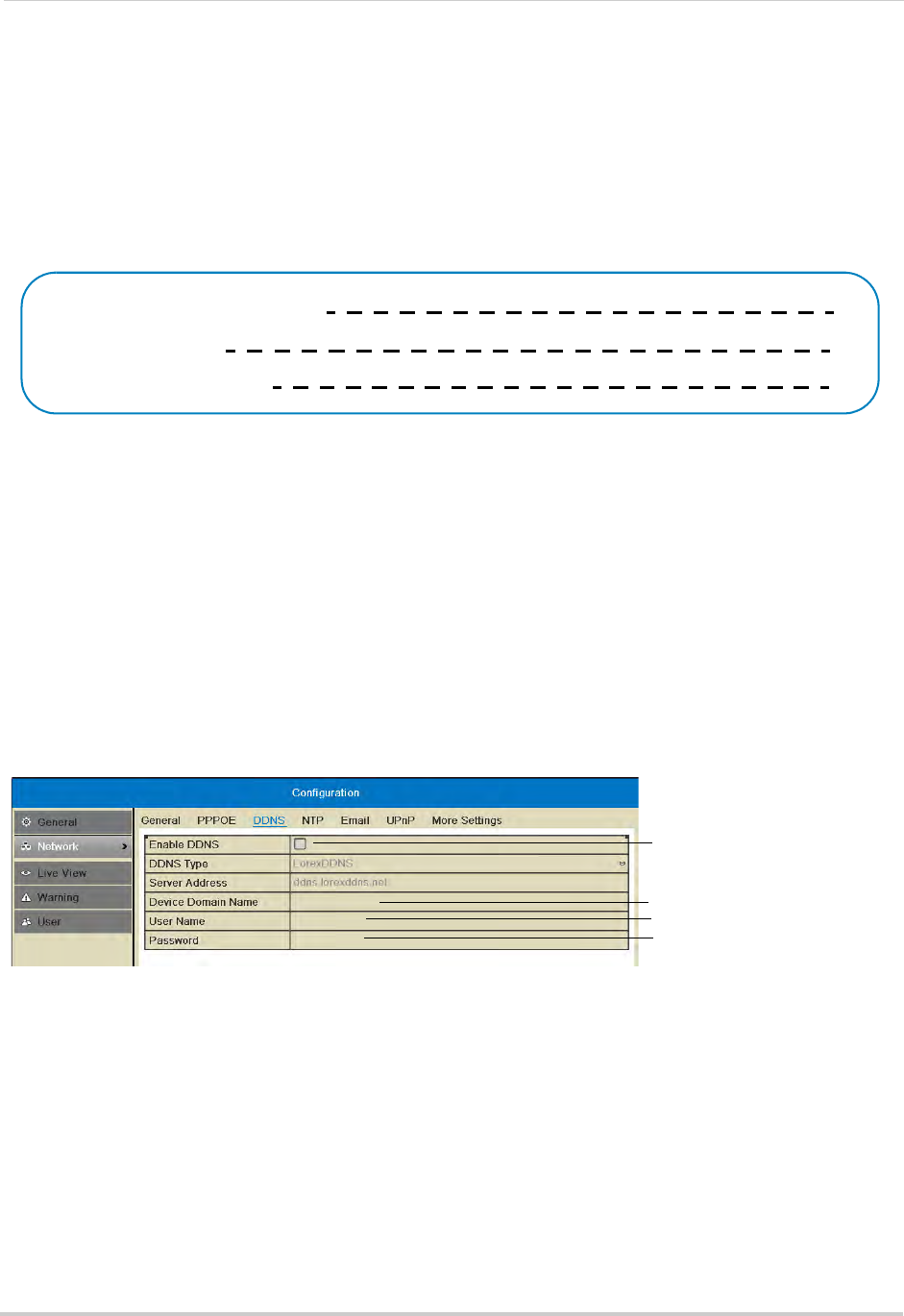
168
Appendix C: DDNS Setup (Advanced)
• URL Request: Enter the web site address that will be used to connect to your Lorex product.
For example, if you enter
tomsmith
, the address to access your video will be
tomsmith.lorexddns.net
.
9Click Save to register your product for DDNS. A confirmation email will be sent to the email
address used to register for My Lorex.
You will need this information to enable remote access to your system. Record your
information below:
Domain name/URL Request:
DDNS User Name:
Device DDNS password:
Step 3 of 4: Enable DDNS on the NVR
To enable DDNS on your NVR:
1Right-click and then click Menu>Configuration>Network>DDNS.
2Check Enable DDNS.
3Configure the following:
• DDNS Type: Select LorexDDNS.
• Device Domain Name: Enter the Domain Name/URL Request you received in the confirmation
email after you set up your DDNS account.
• User Name: Enter the DDNS User Name from the confirmation email.
• Password: Enter the DDNS Device Password from the confirmation email.
Check to enable DDNS
Enter Domain Name/URL
Request
Enter DDNS User Name
Enter DDNS Device Password
tomsmith
tsmith01
******
4Click Apply to save changes. Right-click repeatedly to return to live view.
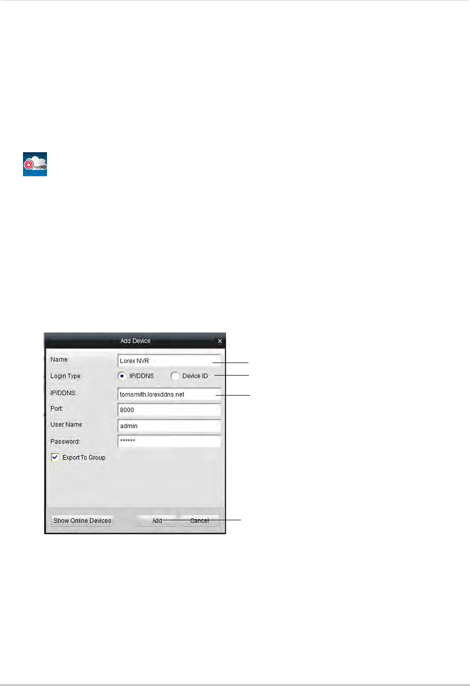
169
Appendix C: DDNS Setup (Advanced)
Step 4 of 4: Connect to the DDNS Address in the Client Software
NOTE: Please allow 10~15 minutes for the DDNS servers to update with your new DDNS address
before attempting to connect.
Finally you must connect to the NVR’s DDNS address. You will use the DDNS address
whenever you want to connect to your NVR over the Internet.
To connect to the NVR’s DDNS address:
1Install the Client Software for PC on a remote computer, and double-click the desktop icon
() to open.
2The Add NVR Wizard opens. Click Enter Wizard.
NOTE: If the Add NVR Wizard doesn’t open, click Help>Open Wizard.
3Click Add.
4Configure the following:
• Nickname: Enter a name for your NVR of your choice (e.g. home or office).
• Login Type: Select IP/DDNS.
• IP/DDNS: Enter the Domain Name/URL Request from the confirmation email, followed by
.lorexddns.net. For example, if your Domain Name/URL Request is
tomsmith
, enter
tomsmith.lorexddns.net
.
Enter a name for your NVR
Enter Domain Name/URL Request,
followed by .lorexddns.net
Click Add
Select IP/DDNS
NOTE: If you have changed the Client Port, User Name, or Password from the defaults, you
must update them to connect to the NVR.
5Click Add.
6Click Next 3 times, then click Finished. The NVR opens in Main View and streams video from
your cameras.
NOTE: If Main View does not open, click Control Panel>Main View to open the Main View menu.
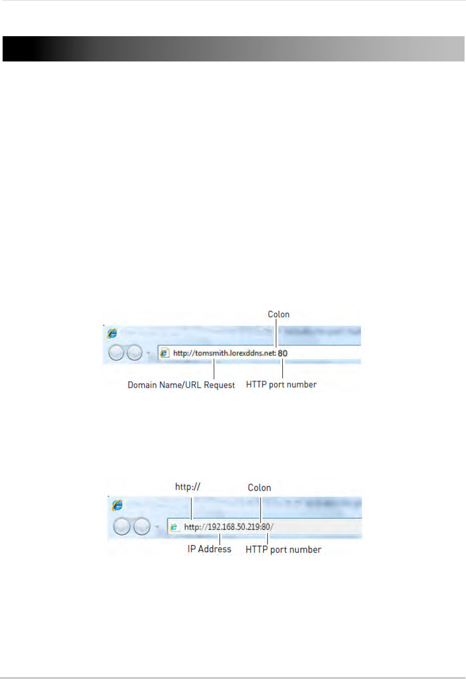
170
Appendix D: Connecting to your NVR Using a Web Browser
Appendix D: Connecting to your NVR Using a Web
Browser
The NVR includes a built in web browser software. You can connect to your NVR in Internet
Explorer 8 and above, Apple Safari, Mozilla Firefox, and Google Chrome.
NOTE: In order to connect to your NVR using a web browser, you must complete port
forwarding and DDNS setup. Complete all the steps under “Appendix C: DDNS Setup
(Advanced)” on page 160.
Connecting to your NVR Using a DDNS or Local IP Address
You must enter your NVR’s DDNS or Local IP address in the address bar to connect using
a web browser.
• A DDNS address is formatted http://, the Domain Name/URL Request you received in the
email after registering for your DDNS account, followed by .lorexddns.net, colon (:), and the
HTTP port of your NVR (e.g.
http://tomsmith.lorexddns.net:80
). A DDNS address is required
to connect to your NVR over the Internet.
• The local IP address is formatted http://, the IP address (can be found by right-clicking and
selecting Information), colon (:), and the HTTP port of your NVR (e.g.
http://192.168.50.219:80
). You may only connect to the local IP address of the NVR within your
own local network.
Connecting Using Internet Explorer
NOTE: The steps below describe how to connect to the NVR in Internet Explorer 9 or 10. The
steps may vary for earlier versions of Internet Explorer.
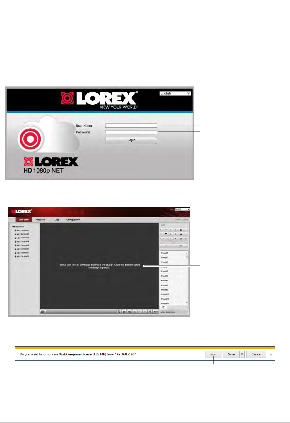
171
Appendix D: Connecting to your NVR Using a Web Browser
1Open Internet Explorer and enter the NVR’s DDNS address or local IP address in the address
bar. For details, see “Connecting to your NVR Using a DDNS or Local IP Address” on
page 170.
NOTE: It is recommended to select Run as Administrator when opening Internet Explorer. This
will allow you to save screenshots and video files to your computer hard drive.
2Enter the User Name and Password for the NVR and click Login. By default, the user name is
admin and the password is 000000.
Enter user name (default: admin)
Enter password (default: 000000)
3The live viewing interface appears and prompts you to install a plug-in. Click the message to
download.
Click to download plugin
4An attention bar appears to ask you to install a web plug-in. Click Run. Follow the prompts to
install the plug-in.
Click Run
5After installing the plug-in, restart Internet Explorer and re-enter the address for the NVR.
Log in again if needed. Another attention bar appears, click Allow to allow Internet Explorer
to run the plug-in.
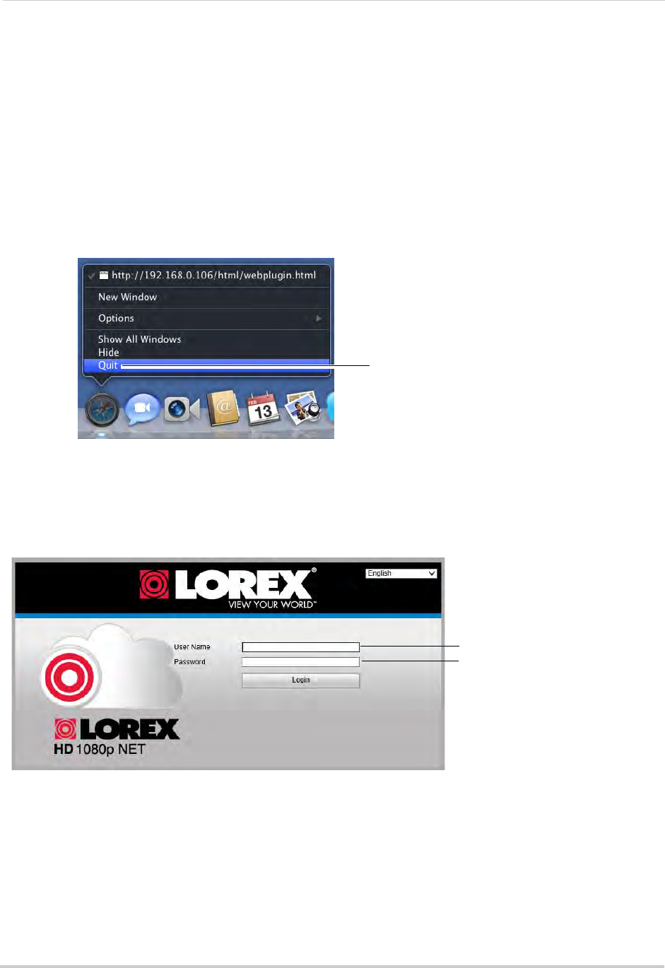
172
Appendix D: Connecting to your NVR Using a Web Browser
6The live viewing interface opens and streams live video from your cameras.
Connecting Using Safari
You must download plug-ins from www.lorextechnology.com to view your cameras in Apple
Safari.
To connect to your NVR in Safari:
1Download and install the Safari Plug-in from www.lorextechnology.com.
2You must quit Safari to complete the installation. Hold right-click on the Safari icon in the
Dock and select Quit.
Hold right-click and select Quit
3Open Safari and enter the NVR’s DDNS address or local IP address in the address bar. For
details, see “Connecting to your NVR Using a DDNS or Local IP Address” on page 170.
4Enter the User Name and Password for the NVR and click Login. By default, the user name is
admin and the password is 000000.
Enter user name (default: admin)
Enter password (default: 000000)
5The live viewing interface opens and streams live video from your cameras.
Connecting Using Chrome/Firefox
1Open Chrome or Firefox and enter the NVR’s DDNS address or local IP address in the
address bar. For details, see “Connecting to your NVR Using a DDNS or Local IP Address” on
page 170.
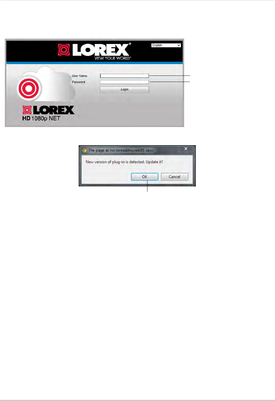
173
Appendix D: Connecting to your NVR Using a Web Browser
2Enter the User Name and Password for the NVR and click Login. By default, the user name is
admin and the password is 000000.
Enter user name (default: admin)
Enter password (default: 000000)
3You are prompted to install a plug-in. Click OK to download the plug-in.
Click OK
4Install the plug-in and then restart your browser.
5Re-enter the address for your NVR. Log in again if needed. The live viewing interface opens
and streams live video from your cameras.
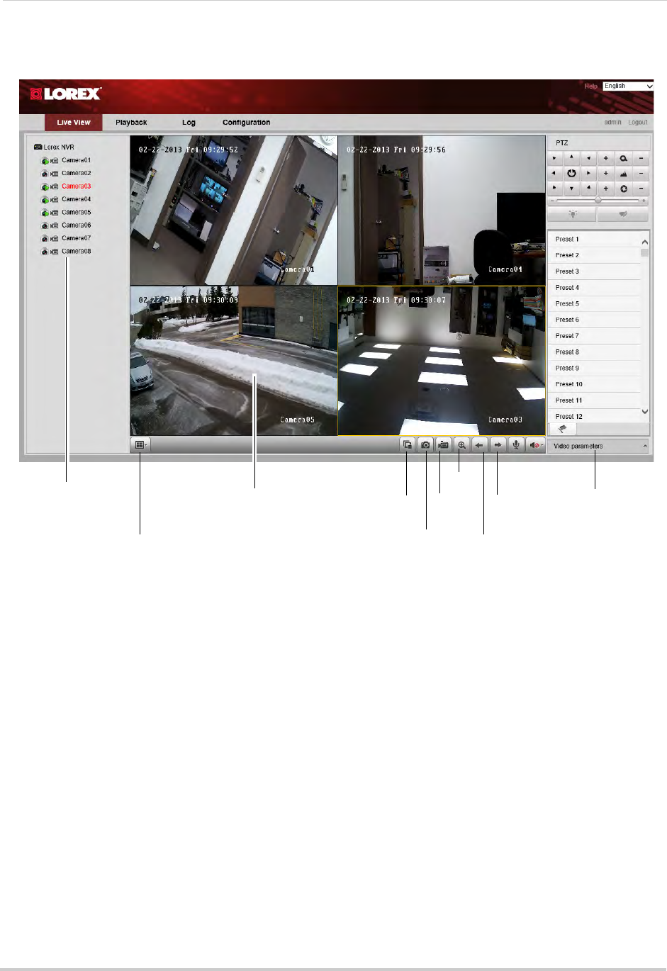
174
Appendix D: Connecting to your NVR Using a Web Browser
Navigating the Web Browser Interface
Double-click to open
cameras in the
selected display area
Select split-screen
layout
Click to select an area Disconnect all
cameras
Screenshot
Manual
recording
Digital
zoom
Previous
page
Next
page
Edit image
settings
NOTE: To view or change where screenshots or manual recordings are saved, click
Configuration>Local Configuration.
Web Browser Remote Playback
You can playback recorded files from your NVR on a web browser.
To access playback mode:
1Click the Playback tab.
2Click a camera to select.
3Select the date you would like to playback in the calendar.
4Click Search.
5Click-and-drag the time bar to select the playback time.
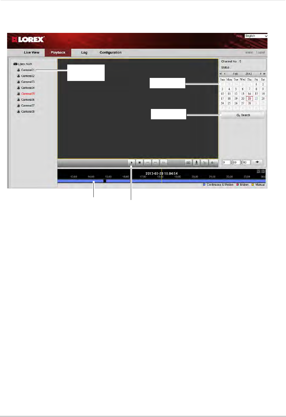
175
Appendix D: Connecting to your NVR Using a Web Browser
6Click to begin playback.
Click to select
camera
Select date
Click Search
Click-and-drag to
select the time Click to start
playback

176
Troubleshooting
Troubleshooting
When a malfunction occurs, it may not be serious and can be corrected easily. The following
describes the most common problems and solutions. Please refer to the following before
calling Lorex Technical Support:
Error Possible Causes Solutions
• System is not
receiving power, or is
not powering up
• Power cable is loose or is
unplugged
• Confirm that all cables are connected correctly
• Confirm that the power cable is securely connected to
the back of the unit
• Power switch is set to OFF (•)
position
• Confirm that the power switch is in the ON (I) position.
• Cables are connected, but
system is not receiving sufficient
power
• Confirm that the system is powered on (LED indicators
on the front should be ON)
• If the unit is connected through a power bar or surge
protector, try bypassing the bar and connecting the
power directly to the wall outlet
• Confirm that there is power at the outlet:
• Connect the power cable to another outlet
• Test the outlet with another device (such as a lamp
or phone charger)
• Remote control is
not detected
• Battery in the remote control is
drained
• Install two fresh AAA alkaline batteries in the remote
control
• There are no batteries in the
remote control
• Hard drive is not
detected by the
system
• Hard drive cables are loose or
not properly connected
• Remove the housing and check that hard drive cables
are firmly connected
• There is no hard drive in the
system
• Open the housing and install a 3.5" SATA hard drive.
For details, see “Appendix B: Installing or Replacing the
Hard Drive” on page 156. Make sure to format the drive
after installing.
• Hard drive is full
and the unit is no
longer recording
• Overwrite is not enabled • Right-click and click Menu>HDD>Overwrite. Ensure
Overwrite is checked and click Apply.
• There is no picture
on monitor/TV after
connecting it to the
NVR
• Monitor/TV not detected by NVR • Power off the monitor/TV and NVR. Power on the
monitor/TV, and then power on the NVR
• Input channel for NVR not
selected on monitor/TV
• On the monitor/TV, select the input channel the NVR is
connected to
• Video cable is loose or has
become disconnected
• Check the video cable connection to the NVR and
monitor/TV

177
Troubleshooting
Troubleshooting (Continued)
Error Possible Causes Solutions
• Mouse not detected
by system
• Mouse cable is not firmly
connected to the system
• Firmly connect the mouse cable to the USB Mouse
port on the front panel
• Mouse is not connected to the
system
• System needs to be reset • Power off the system using the power switch. Firmly
connect a USB mouse to one of the USB ports. Power
the system back on.
• There is no picture
on selected channels
/ camera picture is
not being displayed
• Cameras may take up to 1
minute to power up after
connection
• After connecting the camera to the NVR, wait up to 1
minute. If there is still no picture, follow the
troubleshooting steps below.
• Camera cables have become
disconnected
• Check the Ethernet cable connection at the camera
and system end
• Disconnect and reconnect the cable at the system and
at the camera
• Try moving the camera to another channel or use
another cable
• Syncronize IP Camera is not
checked or other NVR settings
have been changed
• Right-click and then click Menu>Camera. Ensure
Syncronize IP Camera is checked.
• Reset the NVR to Factory Default Settings. Right-click
and then click Menu>Maintenance>Default. Click OK
to reset the NVR to factory default setting.
WARNING: This will erase all configuration
changes you have made to the system. It should be
done as a last resort to ensure that no settings
have been changed that may affect camera
connectivity.
• The system beeps
at startup
• The beep at startup is normal
• The system beeps
during motion
detection
• Motion detection is enabled and
the alarm Audible Warnings are
activated
• To disable the Audible Warnings for motion detection,
see “Configuring Motion Detection Alarm Settings” on
page 59.
• I am not receiving
email notifications
• Email notification is disabled • Ensure you have configured email notification. For
details, see “Configuring Email Alerts” on page 70
• Default setting is disabled, but
you have not entered your own
SMTP information
• If you want to use your own SMTP server, select the
Enable box, and enter your SMTP Server address, Port,
User name, and Password in the respective fields
