Lowrance Electronic X 15A Users Manual
X-15A to the manual e0685ca7-4fba-4b5e-bdf2-7b1797fbbce0
2015-02-05
: Lowrance-Electronic Lowrance-Electronic-X-15A-Users-Manual-407942 lowrance-electronic-x-15a-users-manual-407942 lowrance-electronic pdf
Open the PDF directly: View PDF ![]() .
.
Page Count: 12
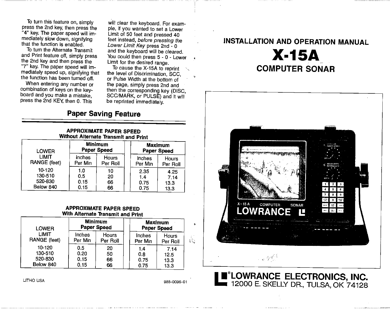
To turn
this feature on, simply
press
the 2nd key, then press the
"4" key. The paper speed will im-
mediately slow
down, signifying
that the function is enabled.
To turn the Alternate Transmit
and Print
feature off, simply press
the 2nd key and then press the
"7" key. The paper speed will im-
mediately speed up, signifying that
the function has been turned oft.
When entering any number or
combination of keys on the key-
board and you
make
a mistake,
press
the 2nd KEY then 0. This
will clear the keyboard. For exam-
ple, if you
wanted to set a Lower
Limit
of 50 feet and pressed 40
feet instead, before
pressing the
Lower
Limit Key press 2nd - 0
and the keyboard will be cleared.
You could then press 5 - 0 - Lower
Limit for the desired range.
To cause the X-15A to reprint
the level of Disbrimination, SCC,
or Pulse Width at the bottom of
the
page, simply press
2nd and
then the corresponding key (DISC,
5CC/MARK,
or PULSE) and it will
be reprinted immediately.
Paper Saving Feature
APPROXIMATE PAPER SPEED
Without Alternate Transmit and Print
Minimum I Maximum
LOWER
LIMIT Paper Speed Paper Speed
Inches Hours Inches Hours
RANGE (feet)
10-120
Per Mm Per Roll Per Mm Per Roll
1.0 10 2.35 4.25
130-510 0.5 20 1.4 7.14
520-830 0.15 66 0.75 13.3
Below 840 0.15 66 0.75 13.3
—
APPROXIMATE PAPER SPEED
With Alternate Transmit and Print
Minimum Maximum
LOWER
LIMIT Paper
Speed Paper Speed
Inches Hours
Inches Hours
RANGE (feet)
10-120
Per Mm Per Roll Per Mm Per Roll
0.5 20 1.4 7.14
130-510 0.20 50 0.8 12.5
520-830 0.15 66 0.75 13.3
Below 840 0.15 66 0.75 13.3
LITHO USA 988-0096-01
INSTALLATION AND OPERATION MANUAL
X-15A
COMPUTER SONAR
•LOWRANCE ELECTRONICS, INC.
12000 F, SKELLY DR, TULSA, OK 74128
PDF compression, OCR, web-optimization with CVISION's PdfCompressor
INDEX
Lower Limit . level whereas the
highest
value
(4) is the strongest
level and
should be used only when severe
noise is present.
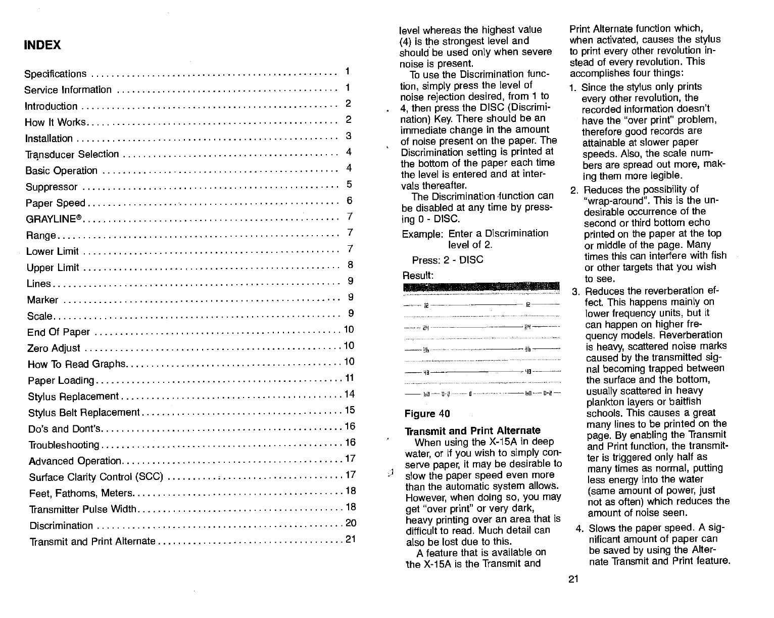
To use the Discrimination func-
tion, simply press the level of
noise
rejection desired, from 1 to
4, then press the DISC (Discrimi-
nation) Key. There should be an
immediate change in the amount
of noise present
on the paper. The
Discrimination setting is printed
at
the bottom of the paper
each time
the level is entered and at inter-
vals thereafter.
The Discrimination -function can
be disabled at any
time by press-
ing
0 - DISC.
Example: Enter a Discrimination
level of 2.
Press: 2 - DISC
Figure 40
Transmit and Print Alternate
When using
the X-15A in deep
17 water, or if
you wish to simply con-
serve
paper, it may
be desirable to
17 slow
the paper speed
even more
than the automatic system allows.
However,
when doing so, you may
get "over print' or
very dark,
heavy printing over an area that is
difficult to read. Much detail can
also be lost due to this.
A feature that is available on
the X-15A is the Transmit and
Print Alternate function which,
when activated,
causes
the
stylus
to print every other
revolution in-
stead of every revolution. This
accomplishes
four things:
1. Since the stylus only prints
every other
revolution, the
recorded information doesn't
have
the "over
printt' problem,
therefore good records are
attainable at slower paper
speeds. Also, the scale
num-
bers are spread out more,
mak-
ing them more legible.
2. Reduces the possibility of
"wrap-around". This
is the un-
desirable occurrence of the
second or third bottom echo
printed on the paper
at the top
or middle of the page. Many
times this can
interfere with fish
or other targets that you wish
to see.
3. Reduces the reverberation ef-
fect. This
happens mainly on
lower frequency units, but it
can happen on higher
fre-
quency models. Reverberation
is heavy, scattered noise marks
caused by the transmitted sig-
nal becoming trapped between
the surface and the bottom,
usually scattered in heavy
plankton layers or baitfish
schools. This
causes a great
many lines
to be printed
on the
page. By enabling the Transmit
and Print function, the transmit-
ter is triggered only half as
many times as normal, putting
less energy into the water
(same amount of power, just
not as often) which reduces the
amount of noise seen.
4. Slows the paper speed. A
sig-
nificant amount of paper
can
be saved by using the Alter-
nate Transmit and Print
feature.
21
Specifications 1
Service Information 1
Introduction 2
How It Works 2
Installation 3
Transducer Selection 4
Basic Operation 4
Suppressor 5
Paper Speed 6
GRAYLINE® 7
Range 7
8
9
9
9
10
10
10
11
..14
.15
.16
.16
Result:
2-——
--• - -- 2
2'I- -••--— ______
Upper Limit
Lines
Marker
Scale
End Of Paper
Zero Adjust
How
To Read
Graphs
Paper Loading
Stylus Replacement
Stylus Belt
Replacement
Do's and Dont's
Troubleshooting
Advanced Operation
Surface
Clarity
Control (SCC)
Feet, Fathoms, Meters 18
Transmitter Pulse Width 18
Discrimination 20
Transmit and Print Alternate 21
PDF compression, OCR, web-optimization with CVISION's PdfCompressor
resolution.
For example, if a 50 ps initial
transmitter pulse length is
selected, and the Suppressor
control is rotated to maximum, the
transmitter pulse length would be
850 ps. Returning the Suppressor
control to minimum will restore the
unit to a 50 ps transmitter pulse
length.
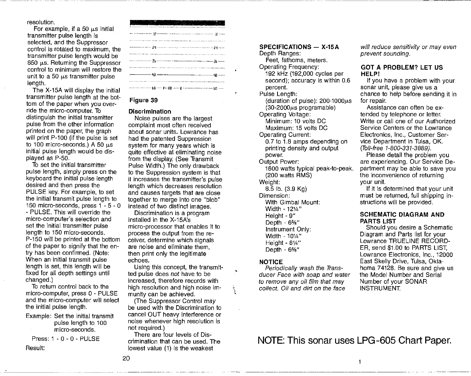
The X-15A will display the initial
transmitter pulse length at the bot-
tom of the paper when
you over-
ride the micro-computer. To
distinguish the initial transmitter
pulse
from the other information
printed on the paper, the graph
will print P-100 (if
the pulse is set
to 100 micro-seconds.) A 50 us
initial pulse length would be dis-
played as P-SO.
To set the initial transmitter
pulse length, simply press on the
keyboard the initial pulse length
desired and then press the
PULSE key. For example, to set
the initial transmit
pulse length to
150 micro-seconds, press 1 - 5 - 0
- PULSE. This will override the
micro-computer's selection and
set the initial transmitter pulse
length to 150 micro-seconds.
P-iSO will be printed at the bottom
of the paper to signify that the en-
try has been confirmed. (Note:
When an initial transmit
pulse
length is set, this length will be
fixed for all depth settings until
changed.)
To return control back to the
micro-computer, press 0 - PULSE
and the micro-computer will select
the initial pulse length.
Example: Set the initial transmit
pulse length to 100
micro-seconds.
Press: 1 - 0 - 0 - PULSE
Result:
---—-bO-—-F-ILU -•-—--
Figure 39
Discrimination
Noise pulses are the largest
complaint most often received
about sonar units. Lowrance has
had the patented Suppression
system
for many years which is
quite
effective at eliminating noise
from the display. (See
Transmit
Pulse Width.)
The
only drawback
to the
Suppression system is that
it increases the
transmitter's pulse
length which decreases resolution
and causes
targets
that are close
together to merge into one "blob"
instead of two distinct images.
Discrimination is a program
installed in the X-15A's
micro-processor that enables it to
process the output
from the re-
ceiver, determine which
signals
are noise and eliminate them,
then print only the legitimate
echoes.
Using this concept, the transmit-
ted pulse
does not have to be
increased, therefore records with
high resolution and high noise im-
munity can be achieved.
(The Suppressor Control may
be used with the Discrimination to
cancel OUT
heavy interference or
noise whenever high resolution is
not required.)
There are four levels of Dis-
crimination that can be used. The
lowest value (1) is the weakest
SPECIFICATIONS — X-15A
Depth Ranges:
Feet, fathoms, meters.
Operating Frequency:
192 kHz (192,000 cycles per
second); accuracy is within 0.6
percent.
Pulse Length:
(duration of pulse): 200-l000ps
(30-2000gs programable)
Operating Voltage:
Minimum: 10 volts DC
Maximum: 15 volts DC
Operating Current:
0.7 to 1.8 amps depending on
printing density
and output
power.
Output Power:
1600 watts
typical peak-to-peak.
(200
watts RMS)
Weight:
8.5 lb. (3.9 Kg)
Dimension:
With Gimbal Mount:
Width - 12¼"
Height - 9"
Depth
- 6%"
Instrument Only:
Width - 101/4"
Height - 8¼"
Depth
- 6%"
NOTICE
Periodically wash the Trans-
ducer Face with soap
and water
to remove
any
oil film that may
collect Oil and dirt on the face
will reduce
sensitivity or
may even
prevent sounding.
GOT A PROBLEM? LET US
HELP!
If you
have a problem with your
sonar unit, please give us a
chance to help
before sending it in
for repair.
Assistance can often be ex-
tended by telephone or letter.
Write or call one of our Authorized
Service Centers or the Lowrance
Electronics, Inc., Customer Ser-
vice Department in Tulsa, OK.
(Toil-free 1-800-331-3889).
Please detail the problem you
are experiencing. Our Service De-
partment may be able to save
you
the inconvenience of returning
your unit.
If it is determined that your unit
must be returned, full shipping
in-
structions will be provided.
SCHEMATIC DIAGRAM AND
PARTS LIST
Should you desire a Schematic
Diagram and Parts list for your
Lowrance TRUELINE RECORD-
ER, send $1.00 to PARTS LIST,
Lowrance Electronics, Inc., 12000
East
Skelly
Drive, Tulsa, Okla-
homa 74128. Be sure and give us
the Model Number and Serial
Number of your SONAR
INSTRUMENT
— Ia—-— —•---••-—- —.
2L1---——.-— ———- 29-—-
20
NOTE: This sonar uses LPG -605 Chart Paper.
PDF compression, OCR, web-optimization with CVISION's PdfCompressor
1. INTRODUCTION
The Lowrance X-15A is a highly
sophisticated recording depth
sounder. Thanks to a micro-com-
puter, the X-1 5A can do more than
any other sonar unit in its price
range plus many that cost much
more. Thanks to a waterproof key-
board, full control of the system is
at your fingertips to meet the
changing demands of varying bot-
tom conditions, water
depth, and
boat speed. You can select the
unit's sensitivity, suppression level,
upper
and lower
depth range, pa-
per speed, GRAYLINE, and many
more features. The patented
Lowrance variable suppression
system
combined with the new
Discrimination feature not only fil-
ters out false signals without dis-
torting the real ones, but is
synchronized with the GRAYLINE
function to provide clear
signals
under all conditions.
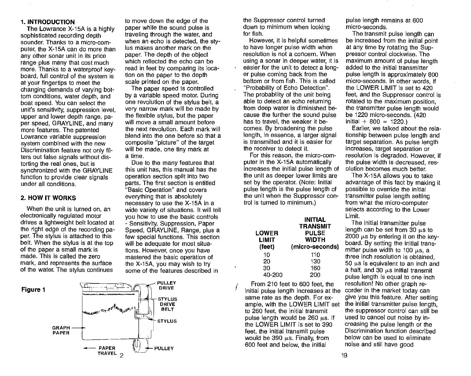
2. HOW IT WORKS
When the unit is turned
on, an
electronically regulated motor
drives a lightweight belt located at
the right edge of the recording pa-
per. The stylus
is attached to this
belt. When the stylus
is at the top
of the paper
a small mark is
made. This is called the zero
mark, and represents the surface
of the water. The stylus
continues
Figure 1
to move down the edge of the
paper
while the sound pulse
is
traveling through the water, and
when an echo is detected, the sty-
lus makes another mark on the
paper. The depth of the object
which reflected the echo can be
read in feet by comparing its loca-
tion on the
paper
to the depth
scale printed on the paper.
The paper speed
is controlled
by a variable speed motor. During
one revolution of the stylus belt, a
very narrow mark will be made by
the flexible stylus, but the
paper
will move a small amount before
the next revolution. Each mark will
blend into the one before so that a
composite "picture"
of the target
will be made, one tiny mark at
a time.
Due to the many
features that
this unit has, this manual has the
operation section split into two
parts. The first section is entitled
"Basic
Operation" and covers
everything that is absolutely
necessary to use
the X-1SA in a
wide variety of situations. It will tell
you how to use the basic controls
- Sensitivity, Suppression, Paper
Speed, GRAYLINE, Range, plus a
few special functions. This section
Will be adequate for most situa-
tions. However, once
you have
mastered the basic operation of
the X-15A, you may.
wish to try
some of the features described in
PULLEY
DRIVE
sTYLUs
DRIVE
B ELT
STYLUS
the Suppressor control turned
down to minimum when looking
for fish.
However, it is helpful sometimes
to have longer pulse
width when
resolution is not a concern. When
using a sonar in deeper
water, it is
easier for the unit to detect a long-
er pulse coming back from the
bottom or from fish. This is called
"Probability of Echo Detection".
The probability of the unit being
able to detect an echo returning
from
deep water is diminished be-
cause the further the sound pulse
has to travel, the weaker it be-
comes. By broadening the pulse
length, in essence, a larger signal
is transmitted and it is easier for
the receiver to detect it.
For this reason, the micro-com-
puter in the X-15A automatically
increases the initial pulse
length of
the unit
as deeper lower limits are
set by the operator. (Note: Initial
pulse length is the pulse length of
the unit when the Suppressor con-
trol is turned to minimum.)
INITIAL
TRANSMIT
PULSE
WIDTH
(micro-seconds)
110
From 210 feet to 600 feet, the
initial pulse length increases at the
same rate as the depth. For ex-
ample, with the LOWER LIMIT set
to 260 feet, the initial transmit
pulse length would be 260 pa If
the LOWER LIMIT is set
to 390
feet, the initial transmit
pulse
would be 390 is. Finally, from
600 feet and below, the initial
pulse length remains at 600
micro-seconds.
The transmit
pulse length can
be increased from the initial point
at any
time by rotating the Sup-
pressor control clockwise. The
maximum amount of pulse length
added to the initial transmitter
pulse length is approximately 800
micro-seconds. In other
words, if
the LOWER LIMIT is set to 420
feet, and the Suppressor control is
rotated to the maximum position,
the transmitter pulse length would
be 1220 micro-seconds. (420
initial + 800 = 1220.)
Earlier, we talked about the rela-
tionship
between pulse length and
target
separation. As pulse length
increases, target separation
or
resolution is degraded. However, if
the pulse width is decreased, res-
olution becomes much better.
The X-15A allows
you
to take
advantage of this fact by making it
possible to override the initial
transmitter pulse
length setting
from what the micro-computer
selects according to the Lower
Limit.
The initial
transmitter pulse
length can be set
from 30 s
to
2000 ps by entering it on the key-
board. By setting the initial trans-
mitter pulse width to 100 s, a
three inch resolution is obtained,
50 ps is equivalent to an inch and
a half, and 30 s initial transmit
pulse length is equal
to one inch
resolution! No other graph re-
corder in the market
today
can
give you this feature. After setting
the initial transmitter pulse length,
the suppressor control can still be
used to cancel out noise
by in-
creasing the pulse length or the
Discrimination function described
below can be used to eliminate
noise and still have good
LOWER
LIMIT
(feet)
10
20
30
40-200
GRAPH
PAPER
130
160
200
PULLEY
TRAVEL 2 19
PDF compression, OCR, web-optimization with CVISION's PdfCompressor
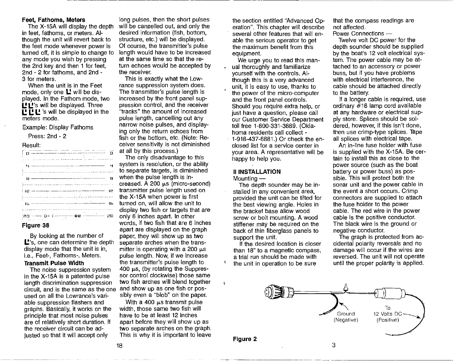
Feet, Fathoms,
Meters
The X-1SA will display the depth
in feet, fathoms, or meters. Al-
though
the unit will revert back to
the feet mode whenever power is
turned
off, it is simple to change to
any
mode you
wish by pressing
the 2nd key and then 1 for
feet,
2nd - 2 for fathoms, and 2nd -
3 for meters.
When the unit is in the Feet
mode, only one U will be dis-
played. In the Fathom mode, two
I.! U's will be displayed. Three
I.! I.! U 's will be displayed in the
meters mode.
Example: Display Fathoms
Press: 2nd - 2
Result:
o -u
H ---—-—-- —----- H
lb lb
20 I -- 20
Figure 38
By looking at the number of
U's, one can determine the depth
display mode that the unit is in,
i.e., Feet-, Fathoms-, Meters.
Transmit
Pulse Width
The noise suppression system
in the X-15A is a patented pulse
length discrimination suppression
circuit, and is the same as the one
used on all the Lowrance's vari-
able
suppression flashers and
graphs. Basically,
it works on the
principle that most noise pulses
are of relatively short duration. If
the receiver circuit can
be ad-
justed
so that it will accept only
long pulses, then the short pulses
will be canelled
out, and only the
desired information (fish, bottom,
structure, etc.) will be displayed.
Of course, the transmitter's pulse
length would have to be increased
at the same time so that the re-
turn echoes would be accepted by
the receiver.
This is exactly what the Low-
rance suppression system does.
The
transmitter's
pulse length is
increased by the front panel sup-
pression control, and the receiver
"tracks" the amount of increased
pulse length, cancelling out any
narrow noise pulses, and display-
ing only the return echoes from
fish or the bottom, etc. (Note: Re-
ceiver sensitivity is not diminished
at all by this process.)
The only disadvantage to this
system is resolution, or the ability
to separate targets,
is diminished
when the pulse length is in-
creased. A 200 s (micro-second)
transmitter pulse length used on
the X-15A when power is first
turned on, will allow the unit to
display two fish or
targets
that are
only 6 inches apart. In other
words, if two fish that are 6 inches
apart are displayed on the graph
paper, they will show
up as two
separate arches when the trans-
mitter is operating with a 200 ps
pulse length. Now, if we increase
the transmitter's pulse length to
400 jis, (by rotating the Suppres-
sor control clockwise) those same
two fish arches will blend together
and show
up as one fish or pos-
sibly even a "blob" on the paper.
With a 400 ps transmit
pulse
width, those same two fish will
have to be at least 12 inches
apart before they will show up as
two separate arches on the graph.
This is why it is important to leave
the section entitled "Advanced Op-
eration". This
chapter
will describe
several other features that will en-
able the serious
operator
to get
the maximum benefit from this
equipment.
We urge you
to read this man-
ual thoroughly and familiarize
yourself with the controls. Al-
though this is a
very advanced
unit, it is easy
to use, thanks to
the power
of the micro-computer
and the front panel controls.
Should you require extra help, or
just have a question, please call
our Customer Service Department
toll free 1-800-331-3889. (Okla-
homa residents call collect
-
1-918-437-6881.) Or check the en-
closed list for a service center in
your area. A representative will be
happy to help you.
II INSTALLATION
Mounting —
The depth sounder
may
be in-
stalled in any
convenient area,
provided the unit can be tilted for
the best
viewing angle. Holes in
the bracket base allow
wood
screw or bolt mounting. A wood
stiffener may
be required on the
back of thin
fiberglass panels
to
support
the unit.
If the desired location is closer
than 18" to a magnetic compass,
a trial run should
be made with
the unit in operation to be sure
that the
compass readings are
not affected.
Power Connections —
Twelve volt DC power for the
depth sounder should be supplied
by the boat's 12 volt electrical sys-
tem. The power cable
may be at-
tached to an accessory or power
buss, but if you have problems
with electrical interference, the
cable should be attached directly
to the battery.
If a longer
cable is required, use
ordinary #18 lamp cord available
at any
hardware or electrical sup-
ply store. Splices should be sol-
dered, however, if this isn't done,
then use
crimp-type splices. Tape
all splices
with electrical tape.
An
in-line fuse holder with fuse
is supplied with the X-15A. Be cer-
tain to install this as close to the
power source (such as the boat
battery or power buss) as pos-
sible. This will protect both the
sonar unit and the power cable in
the event a short occurs. Crimp
connectors are supplied to attach
the fuse holder to the power
cable. The red wire in the power
cable is the positive conductor.
The black wire is the ground
or
negative conductor.
The graph is protected from ac-
cidental polarity reversals and no
damage will occur if the wires are
reversed. The unit
will not operate
until the
proper polarity is applied.
9 —-— --——--.--—-— 8
2 - 2
Figure 2
18 3
Ground
(Negative)
PDF compression, OCR, web-optimization with CVISION's PdfCompressor
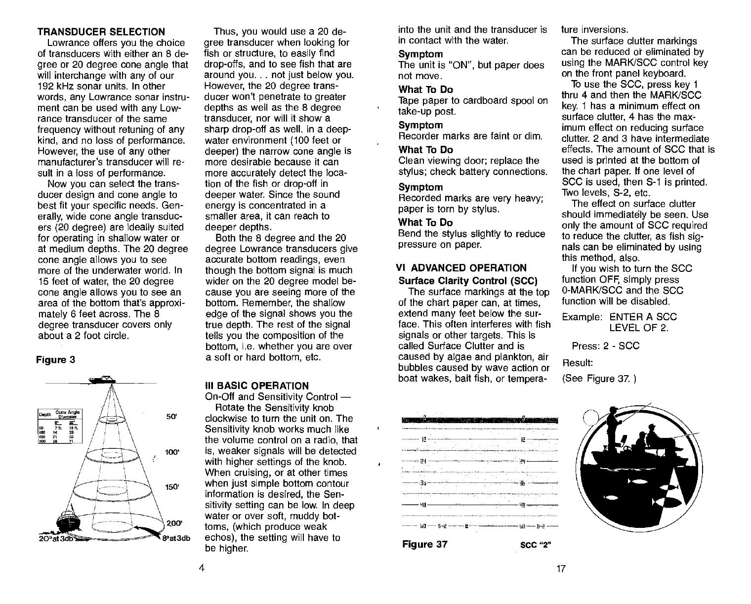
TRANSDUCER SELECTION
Lowrance offers you the choice
of transducers With either an 8 de-
gree or 20 degree cone
angle that
will interchange with any
of our
192 kHz sonar units. In other
words, any Lowrance sonar instru-
ment can
be used with any Low-
rance transducer of the same
frequency without
retuning of any
kind, and no loss of performance.
However, the use of any
other
manufacturer's transducer will re-
sult in a loss of performance.
Now
you
can select the trans-
ducer design and cone angle to
best fit your specific
needs. Gen-
erally, wide cone
angle transduc-
ers (20 degree) are ideally suited
for operating in shallow water or
at medium depths. The 20 degree
cone
angle allows
you to see
more of the underwater world. In
15 feet of
water, the 20 degree
cone
angle
allows
you
to see an
area of the bottom that's approxi-
mately
6 feet across. The 8
degree
transducer covers only
about a 2 foot circle.
Figure 3
Thus, you
would use a 20 de-
gree
transducer when looking for
fish or structure, to easily find
drop-offs, and to see fish that are
around you. . . not just below you.
However, the 20 degree trans-
ducer won't penetrate to greater
depths as well as the 8 degree
transducer, nor will it show a
sharp drop-off
as well. In a
deep-
water environment (100 feet or
deeper) the narrow cone angle
is
more desirable because it can
more
accurately detect the loca-
tion of the fish or
drop-off in
deeper water. Since the sound
energy
is concentrated in a
smaller area, it can reach to
deeper depths.
Both the 8 degree
and the 20
degree Lowrance transducers give
accurate bottom readings, even
though
the bottom signal is much
wider on the 20 degree model be-
cause
you are seeing more of the
bottom. Remember, the shallow
edge of the signal shows you
the
true depth. The rest of the signal
tells you the composition of the
bottom, i.e. whether
you are over
a soft or hard bottom, etc.
III BASIC OPERATION
On-Off and Sensitivity
Control —
Rotate the Sensitivity knob
50' clockwise to turn the unit on. The
Sensitivity knob works much like
the volume control on a radio, that
100' is, weaker
signals
will be detected
with higher settings
of the knob.
When cruising, or at other times
when
just simple bottom contour
information is desired,
the Sen-
sitivity setting
can be low. In deep
water or over soft, muddy bot-
zoo' toms, (which produce weak
8°at3db echos), the setting
will have to
be higher.
into the unit and the transducer is
in contact with the water.
Symptom
The unit is "ON", but paper
does
not move.
What To Do
Tape paper
to cardboard spool
on
take-up post.
Symptom
Recorder marks are faint or dim.
* What To Do
Clean viewing door; replace the
stylus; check
battery
connections.
Symptom
Recorded marks are very heavy;
paper is torn by stylus.
What To Do
Bend the stylus slightly to reduce
pressure on paper.
VI ADVANCED OPERATION
Surface
Clarity
Control (SCC)
The surface markings at the top
of the chart paper can, at times,
extend many feet below the sur-
face. This often interferes with fish
signals or other
targets. This
is
called Surface Clutter and is
caused by algae
and plankton, air
bubbles caused by wave action or
boat wakes, bait
fish, or tempera-
ture inversions.
The surface clutter markings
can be reduced or eliminated by
using the MARKJSCC control key
on the front panel keyboard.
To use the
SCC, press
key 1
thru 4 and then the MARK/SOC
key. 1 has a minimum effect on
surface clutter, 4 has the max-
imum effect on reducing surface
clutter. 2 and 3 have intermediate
effects. The amount of SCC that is
used is printed at the bottom of
the chart paper. If one level of
SOC is used, then S-i is printed.
Two
levels, S-2, etc.
The effect on surface clutter
should immediately be seen. Use
only the amount of SOC required
to reduce the clutter, as fish sig-
nals can be eliminated by using
this method, also.
If you
wish to turn the SOC
function OFF, simply press
0-MARK/SOC and the
SOC
function will be disabled.
Example: ENTER A SOC
LEVEL OF 2.
Press: 2 - SCO
Result:
(See Figure 37.
4 _17
Depth C,,,
Angle I
Diameter I
L. it g I
0:- gt I
1,0, 14 30 I
It" it 53 I
12,0 20 70 I
20'at:
l2-----—-
I—
Figure 37 SCC "2"
PDF compression, OCR, web-optimization with CVISION's PdfCompressor
wheels by reversing
the
proce-
dure used to remove the old
one. BE SURE
the fingers of
the new stylus
are pointed UP.
6. Close the front of the case.
Latch both catches at the top
of the unit.
MAINTENANCE
NOTE: The stylus may be
damaged if it is in front of the pla-
ten when the
platen assembly is
pulled down. Always
move the
stylus
to the
back side of the pla-
ten when
changing the
paper
rolls. Remember to move the belt
down to remove the
stylus.
Black carbon dust is created dur-
ing
the recording process. Use a
soft, oil-free
rag to clean the
viewing door and metal platen be-
hind the
paper. Low pressure
compressed air may
be used to
blow dust out of the case and
away from moving parts if the air
is dry and free of oil.
All mechanical connections
should be checked periodically to
be sure they
haven't worked
loose.
HIGH VOLTAGE is present
in the
transmitter section when the
unit
is ON. No attempt
should be
made by any unauthorized per-
son to modify or repair
the elec-
tronic section.
All electrical connections should
be checked periodically and
cleaned as necessary.
The
face of the transducer, if
mounted on the transom
should
be washed periodically with mild
soapy water to remove
any ac-
cumulated rod grime or oily film.
This is essential to have
good
contact between the transducer
16
and the water.
DO SECTION
Do carry a spare fuse, stylus belt,
and roll of paper.
Do use
the empty cardboard core
from the last roll of paper
on the
take-up post.
Do keep the recorded graphs
for
future reference.
Do clean the stylus belt, wheels,
and the rubber roller after
every
five rolls ofpaper.
DON'T
SECTION
DONT OPEN THE CASE WHEN
THE UNIT IS ON.
Don't
pull the platen
assembly
down when the stylus
is at the
front.
Don't store any objects
inside the
case or behind the viewing
win-
dow. (Except for small pieces of
tape.)
Don't
forget
to tape the paper to
the take-up
core.
Don't rotate the stylus belt up.
Don't use
oily cloths, strong sol-
vents, or abrasive cleansers.
TROUBLESHOOTING SECTION
Symptom
On/Off switch is 'ON", but the
stylus and paper
don't move.
What To Do
Check fuse;
check connections at
battery for tightness and
corrosion.
Symptom
On/Off
switch is "ON", have
zero
mark, but no echoes or bottom
signal.
What To Do
Be sure the transducer is plugged
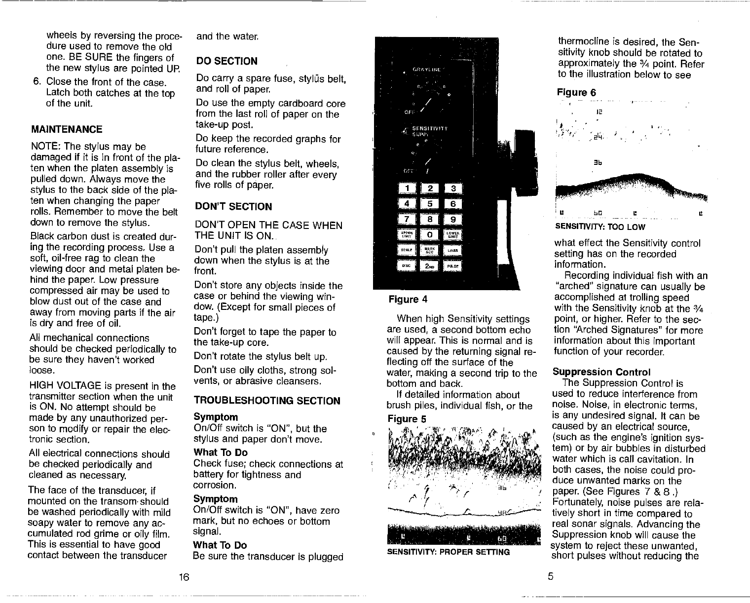
— GRAYL NI
/ -
rrIviv
Han
'nan
a n--• a.
r
Figure 4
When high Sensitivity settings
are used, a second bottom echo
will appear.
This is normal and is
caused by the returning signal re-
flecting
off the surface of the
water, making a second trip to the
bottom and back.
If detailed information about
brush piles, individual fish, or the
I
thermocline is desired, the Sen-
sitivity knob should be rotated to
approximately the ¾ point. Refer
to the illustration below to see
Figure 6
2
'1
SENSITIVITY: TOO LOW
what effect the Sensitivity control
setting has on the recorded
information.
Recording individual fish with an
"arched" signature can usually
be
accomplished at trolling speed
with the Sensitivity
knob at the ¾
point, or higher. Refer to the sec-
tion "Arched Signatures" for more
information about this important
function of your recorder.
Suppression Control
The Suppression Control is
used to reduce interference from
noise. Noise, in electronic terms,
is any
undesired signal. It can be
caused by an electrical source,
(such as the
engine's ignition sys-
tem) or by air bubbles in disturbed
water which is call cavitation. In
both cases, the noise could
pro-
duce unwanted marks on the
paper. (See Figures 7 &
8.)
Fortunately, noise pulses are rela-
tively
short in time
compared to
real sonar signals. Advancing the
Suppression knob will cause
the
system to reject these
unwanted,
short pulses without
reducing the
5
Figure 5
SENSITIVITY: PROPER SETTiNG
PDF compression, OCR, web-optimization with CVISION's PdfCompressor
sensitivity in any way.
This
patented design is exclu-
sive with Lowrance. However,
with
high suppression settings, the
graph record becomes coarse and
the ability
to separate fish from
the bottom or from other fish will
be decreased. (See Figure
9 &1O.) Therefore, the lower the
suppression selling,
the better.
Advance the knob setting only as
far as necessary to remove the er-
I 'wtrM4QWteI1*Ltts4vna JMPI
•' { ISiM •••. 3
,.vcvi iif4L'
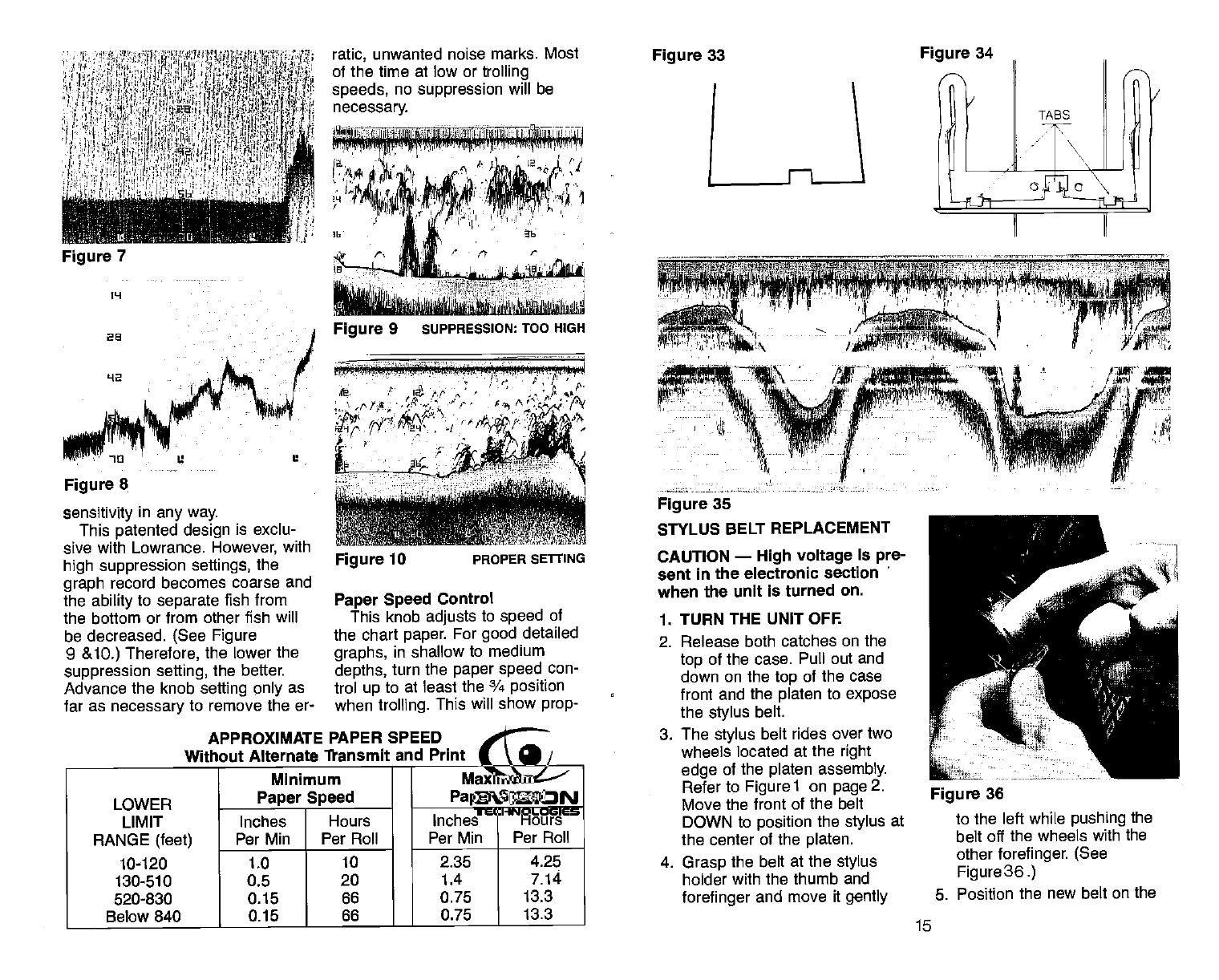
Figure 35
STYLUS BELT REPLACEMENT
CAUTION — High voltage is pre-
sent
in the electronic section
when the unit is turned on.
1. TURN
THE UNIT OFF.
2. Release both catches on the
top
of the case. Pull out and
down on the top of
the case
front and the platen to expose
the
stylus
belt.
3. The stylus belt
rides over two
wheels located at the
right
edge of the
platen assembly.
Refer to Figurel on page2.
Move the front
of the belt
DOWN to position the stylus at
the center
of the
platen.
4. Grasp the belt at the
stylus
holder with the thumb and
forefinger
and move it
gently
ratic, unwanted noise marks. Most
of the time at low or trolling
speeds,
no suppression will be
necessary.
Figure 7
ppj P Vp fl
'a L2
Figure 9 suPPRESSION:
TOO HIGH
Figure 33 Figure 34
1L1
as
42
Figure 8
Figure 10 PROPER SETtING
Paper Speed
Control
This knob adjusts to speed of
the chart paper. For good detailed
graphs, in shallow to medium
depths, turn the
paper speed con-
trol up to at least the ¾ position
when
trolling. This will show
prop-
APPROXIMATE PAPER SPEED
Without
Alternate fransmit and Print
LOWER
LIMIT
Minimum
Paper Speed
Maximum
Paper
Speed
Inches Hours Inches Hours
RANGE (feet)
10-120
Per Mm Per Roll Per Mm Per Roll
1.0 10 2.35 4.25
130-510 0.5 20 1.4 7.14
520-830 0.15 66 0.75 13.3
Below 840 0.15 66 0.75 13.3
N-
Figure 36
to the left while
pushing the
belt off the wheels with the
other
forefinger. (See
Figure
36.)
5. Position the new belt on the
15
PDF compression, OCR, web-optimization with CVISION's PdfCompressor
800' & Below
14 7
RANGE
the control too far or it will gray
line on the target completely,
showing no black, which makes
the target
difficult to see.
- 12
p
C
At
t 4.
. a'
(t
p.
/. ,. (•
t,a
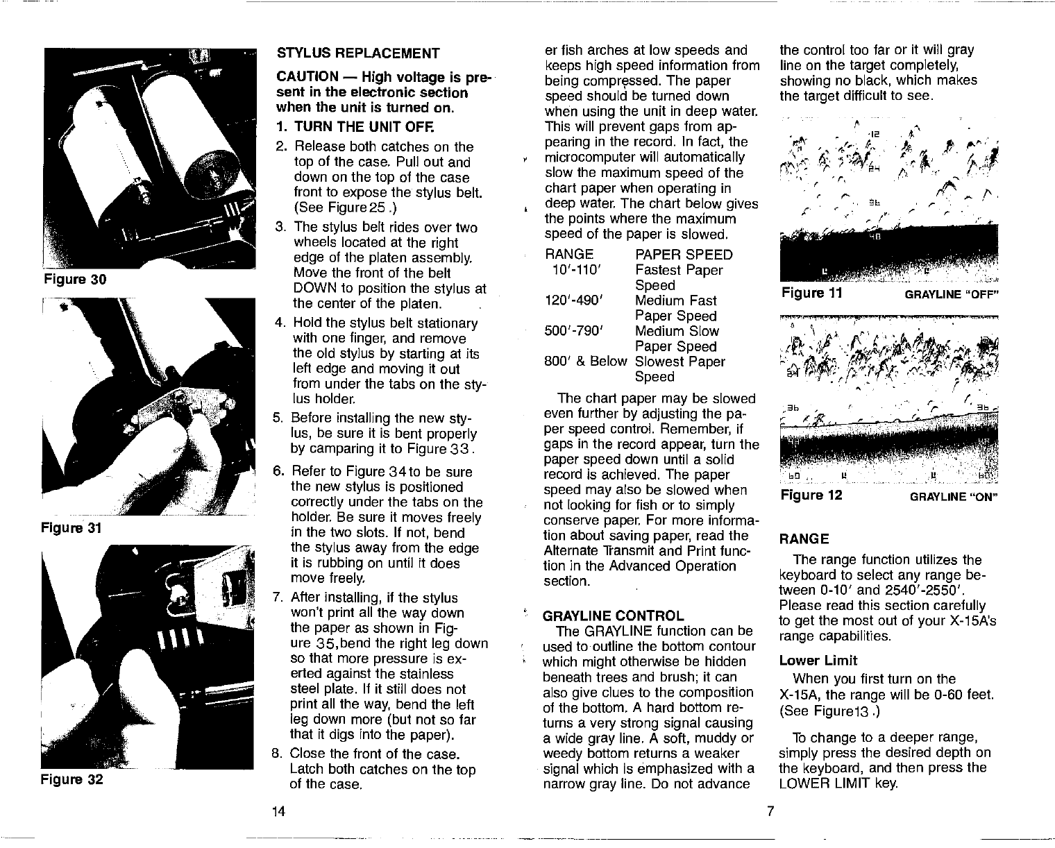
STYLUS REPLACEMENT er fish arches at low speeds
and
CAUTION — High voltage is pre-
sent in the electronic section
when the unit is turned on.
keeps high speed information from
being comprçssed. The paper
speed should be turned down
when using the unit in deep water.
1. TURN
THE UNIT OFF. This will prevent gaps
from ap-
2. Release both catches on the
top of the case. Pull out and
down on the
top of the case
front
to expose the
stylus
belt.
(See Figure 25.)
3. The stylus belt rides over two
wheels located at the
right
edge of the platen assembly.
Move the front of the belt
,
:
pearing in the record. In fact, the
microcomputer will automatically
slow
the maximum speed
of the
chart paper when
operating in
deep water. The chart below gives
the points
where the maximum
speed of the paper is slowed.
RANGE PAPER SPEED
10'llO' Fastest Paper
DOWN to position the stylus at
the center of the platen.
4. Hold the stylus belt
stationary
with one finger, and remove
the old
stylus by starting at its
left
edge and moving it out
from under the tabs on the sty-
lus holder.
Speed
120'-490' Medium Fast
Paper Speed
500'-790' Medium Slow
Paper Speed
Slowest Paper
Speed
The chart paper may
be slowed
5. Before installing the new sty-
lus, be sure it is bent properly
by camparing it to Figure 33.
6. Refer to Figure 34to be sure
the new stylus
is positioned
correctly under the tabs on the
holder. Be sure it moves freely
in the two slots. If not, bend
the stylus
away
from the edge
it is rubbing on until it does
move freely.
7. After
installing, if
the
stylus
won't print all the
way down
the paper
as shown in Fig-
ure 35,bend the right leg down
.
'
even further
by adjusting the pa-
per speed control. Remember, if
gaps
in the record appear, turn the
paper speed down until a solid
record is achieved. The paper
speed may
also be slowed when
not looking for fish or to simply
conserve paper. For more informa-
tion about saving paper, read the
Alternate Transmit and Print func-
tion in the Advanced Operation
section.
GRAYLINE CONTROL
The GRAYLINE function can be
used to outline the bottom contour
The range
function utilizes the
keyboard to select
any range be-
tween 0-10' and 2540'-2550'.
Please read this section
carefully
to get the most out of your X-1SA's
range capabilities.
so that more pressure is ex-
erted against the stainless
steel plate. If it still does not
print all the way, bend the left
leg down more (but
not so far
that it digs into the
paper).
which might otherwise be hidden
beneath trees and brush; it can
also give clues to the composition
of the bottom. A hard bottom re-
turns a very strong signal causing
a wide gray line. A soft, muddy or
Lower Limit
When you
first turn on the
X-15A, the range will be 0-60 feet.
(See Figure 13.)
To change to a deeper range,
8. Close the front of the case. weedy bottom returns a weaker simply press the desired depth on
Latch both catches on the top
of the case. signal which is emphasized with a
narrow gray line. Do not advance the keyboard, and then press
the
LOWER LIMIT
key.
Figure 12 GRAYLINE "ON"
PDF compression, OCR, web-optimization with CVISION's PdfCompressor
12
— -36---
MB
—U—I --L'-- —----611--U—l -
Figure 13
Example: Change range to 0-80
feet.
Press: 8- 0 - LOWER LIMIT
The depth will then be displayed.
16-— --——-——
6--—----
LI0_ -_________
6M
U11-----D-I-— — -
Figure 14
Any depth in a multiple of ten
(10,
20, 30, 500, etc.) may be
used as a lower limit displayed at
the bottom of the chart paper.
Example: Change range
to 0-150
feet.
Press: 1 - 5 - 0 - LOWER LIMIT
The depth will then be displayed:
(See Figure 15.)
Note that the
paper speed
slows automatically at this range
setting.
UPPER LIMIT
Many times it is desirable to ex-
-- 30 -—-----—————- —-——— an —
-- 60 ——-—-—---—---——-—--- 60
-- 90—- —-—-—------——— 90—
—12n —120—
Figure 15
pand a section of the area that is
displayed on the graph recorder to
show more detail. This is made
possible by the X-15A to show
segments of the underwater world
by using
the UPPER LIMIT func-
tion. Using the UPPER LIMIT key
allows
you
to display any depth
range in multiples of 10 at the top
of the chart paper.
Example: Turn on unit and set
range
to 20-60 feet.
Press: 2 - 0 - UPPER LIMIT
The depth will then be displayed.
- -
—26 --
- ——-— —-- -
—92 - -52
- 62-—fl-
L-hB B- I-
Figure 16
Example: Set range to 40-60 feet.
Press: 4— 0 - UPPER LIMIT
The range will then be displayed:
(See Figure17.)
The Upper and. Lower Limits
can be used in various combina-
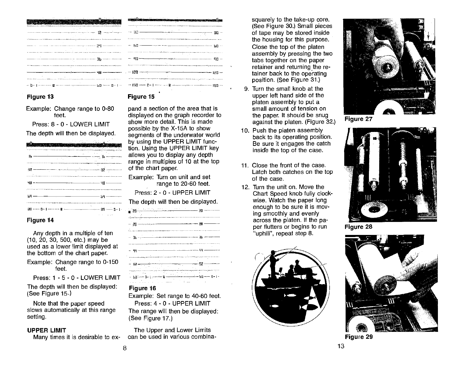
squarely to the take-up
core.
(See Figure 30.) Small pieces
of tape may
be stored inside
the housing for this purpose.
Close the top of the
platen
assembly by pressing the two
tabs together on the paper
retainer and returning the re-
tainer back to the operating
position. (See Figure 31.)
9. Turn the small knob at the
upper
left hand side of the
platen assembly to put a
small
amount of tension on
the paper. It should be snug
against
the
platen. (Figure 32.)
10. Push the platen assembly
back to its operating position.
Be sure it engages
the catch
inside the top of the case.
11. Close the front of the case.
Latch both catches on the
top
of the case.
12. Turn the unit on. Move the
Chart
Speed knob
fully clock-
wise. Watch the paper long
enough to be sure it is mov-
ing smoothly and evenly
across the platen. If the
pa-
per flutters or begins to run
'uphill", repeat step
8.
8 13
Figure 29
PDF compression, OCR, web-optimization with CVISION's PdfCompressor
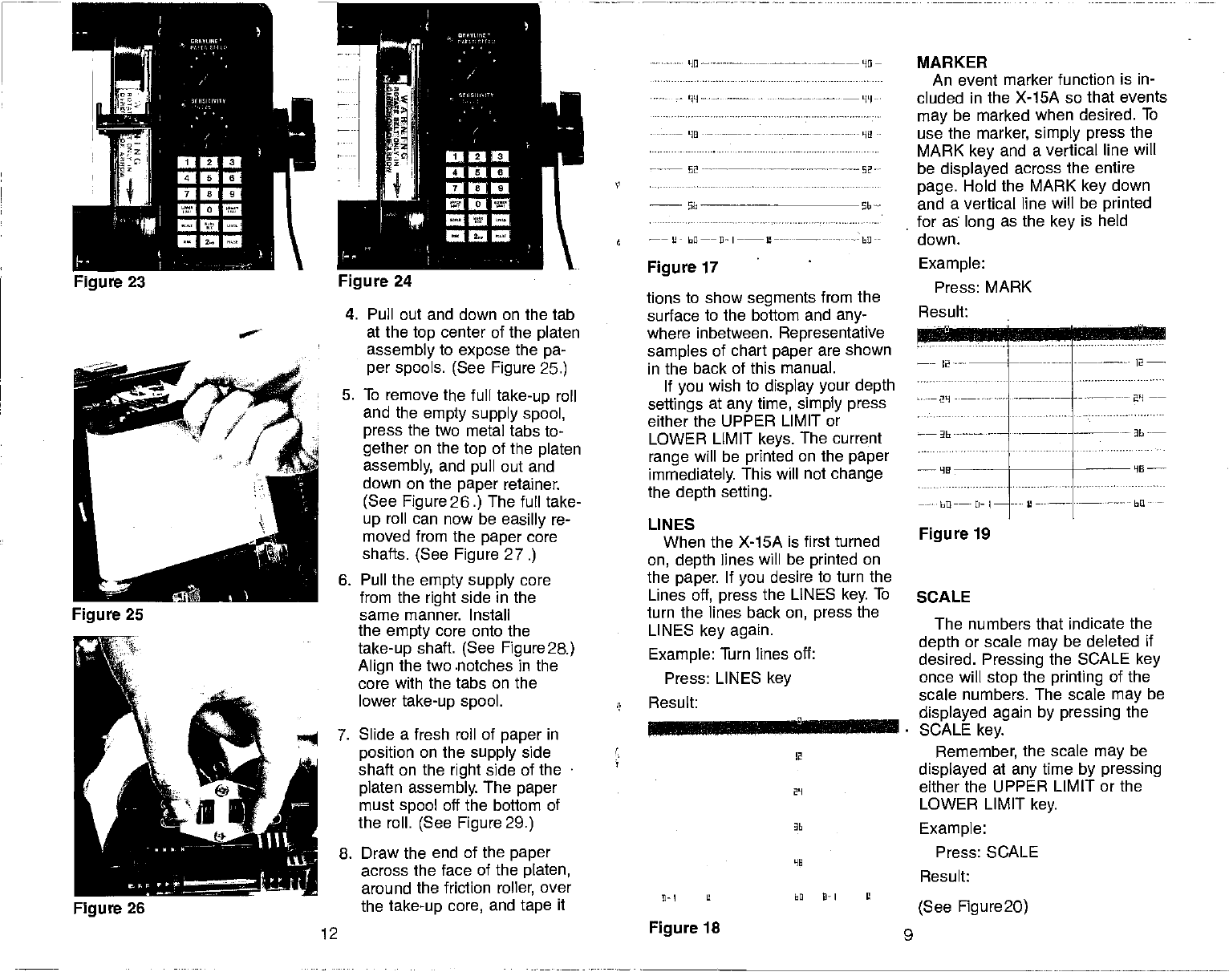
4. Pull out and down on the tab
at the top center of the platen
assembly to expose
the pa-
per spools. (See Figure 25.)
5. To remove the full take-up roll
and the empty supply spool,
press the two metal tabs to-
gether
on the top of the platen
assembly, and pull out and
down on the paper retainer.
(See
Figure 26.) The furl take-
up roll can now be easilly
re-
moved from the paper
core
shafts. (See Figure 27.)
6. Pull the empty supply
core
from the right side in the
same manner. Install
the empty
core onto the
take-up
shaft. (See Figure2a)
Align the two .notches in the
core with the tabs on the
lower
take-up spool.
7. Slide a fresh roll of paper in
position
on the supply side
shaft on the
right
side of the
platen assembly. The paper
must
spool off the bottom of
the roll. (See Figure 29.)
8. Draw the end of the paper
across the face of the platen,
around the friction roller, over
the
take-up core, and tape it
tions to show segments from the
surface to the bottom and any-
where inbetween. Representative
samples of chart paper are shown
in the back of this manual.
If you
wish to display your depth
settings at any
time,
simply press
either the UPPER LIMIT or
LOWER LIMIT keys. The current
range
will be printed on the paper
immediately. This will not change
the depth setting.
LINES
When the X-15A is first turned
on, depth lines will be printed on
the paper. If you
desire to turn the
Lines
off, press the LINES key. To
turn the lines back
on, press the
LINES key again.
Example: Turn lines off:
Press: LINES key
Result:
MARKER
An
event marker function is in-
cluded in the X-15A so that events
may
be marked when desired. To
use the
marker, simply press
the
MARK key and a vertical line will
be displayed across the entire
page. Hold the MARK key down
and a vertical line will be printed
for as long as the
key is held
down.
Figure 19
SCALE
Lw
:i.bU...I..
The numbers that indicate the
depth or scale may
be deleted if
desired. Pressing the SCALE key
once will stop the printing of the
scale numbers. The scale may
be
displayed again by pressing the
SCALE key.
Remember, the scale
may be
displayed at any
time by pressing
either the UPPER LIMIT or the
LOWER LIMIT key.
Example:
Press: SCALE
Result:
(See Figure2O)
'II ————HO—
'UI
Figure 23 Figure
24
02
- —
6 —— bfl——fl—I—--L'—--- - hO--
Figure 17 Example:
Press: MARK
Result:
2
----- —---- --—- 12
—
HE
bU
-—-
2-
I
Figure 26
2
- 29
D—I U EQ lI—I Ii
12 Figure 18 9
PDF compression, OCR, web-optimization with CVISION's PdfCompressor
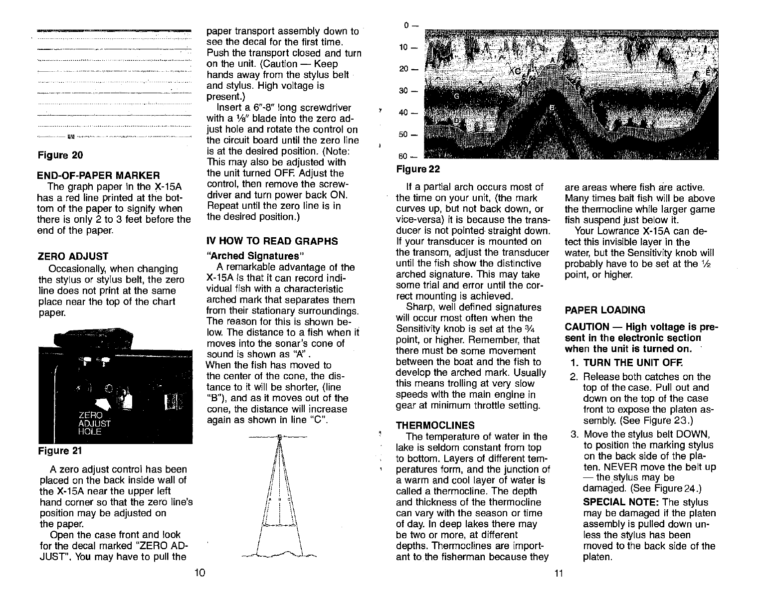
Figure 20
END-OF-PAPER MARKER
The graph paper
in the X-1SA
has a red line printed at the bot-
tom of the
paper
to signify
when
there is only 2 to 3 feet before the
end of the
paper.
ZERO ADJUST
Occasionally, when
changing
the stylus
or stylus belt, the zero
line does not print at the same
place near the
top of the chart
paper.
A zero adjust
control has been
placed
on the back inside wall of
the X-15A near the upper
left
hand corner so that the zero line's
position may be adjusted on
the paper.
Open the case front and look
for the decal marked 'ZERO AD-
JUST". You may have to pull the
paper transport assembly
down to
see the decal for the first time.
Push the transport
closed and turn
on the unit. (Caution —
Keep
hands away from the
stylus
belt
and stylus. High voltage
is
present.)
Insert a 6"-8" long
screwdriver
with a 1/s" blade into the zero ad-
just
hole and rotate the control on
the circuit board until the zero line
is at the desired position. (Note:
This may
also be adjusted with
the unit turned OFF. Adjust
the
control, then remove the screw-
driver and turn power
back ON.
Repeat until the zero line is in
the desired position.)
IV HOW TO READ GRAPHS
"Arched Signatures"
A remarkable advantage of
the
X-15A is that it can record indi-
vidual fish with a characteristic
arched mark that separates
them
from their stationary surroundings.
The reason for this is shown be-
low. The distance to a fish when it
moves into the sonar's cone of
sound is shown as "A".
When the fish has moved to
the center of the cone,
the
dis-
tance to it will be shorter, (line
"B"), and as it moves out of the
cone, the distance will increase
again as shown in line "C".
50 —
so —
Figure
22
If a partial arch occurs most of
the time on your unit, (the
mark
curves up, but not back
down, or
vice-versa) it is because the trans-
ducer is not pointed straight
down.
If your
transducer is mounted on
the transom, adjust
the transducer
until the fish show the distinctive
arched signature. This may
take
some trial and error until the cor-
rect mounting is achieved.
Sharp, well defined signatures
will occur most often when the
Sensitivity knob is set at the ¾
point, or higher. Remember, that
there must be some movement
between the boat and the fish to
develop the arched mark. Usually
this means trolling at very
slow
speeds with the main engine in
gear at minimum throttle setting.
THERMOCLINES
The
temperature of water in the
lake is seldom constant from
top
to bottom. Layers of different tem-
peratures form, and the
junction
of
a warm and cool layer
of water is
called a thermocline. The depth
and thickness of the thermocline
can vary
with the season or time
of day. In deep lakes there may
be two or more, at different
depths. Thermoclines are import-
ant to the fisherman because they
are areas where fish are active.
Many times bait fish will be above
the thermocline while
larger game
fish suspend just below it.
Your Lowrance X-15A can de-
tect this invisible layer
in the
water, but the Sensitivity knob will
probably have to be set at the 1/2
point, or higher.
PAPER LOADING
CAUTION — High voltage is pre-
sent in the electronic section
when the unit is turned on. -
1. TURN THE UNIT OFF.
2. Release both catches on the
top of the case. Pull out and
down on the top of the case
front to expose the
platen as-
sembly. (See Figure 23.)
3. Move the stylus belt
DOWN,
to position the marking stylus
on the back side of the pla-
ten. NEVER move the belt
up
— the stylus may be
damaged. (See Figure 24.)
SPECIAL NOTE: The stylus
may
be damaged if the platen
assembly is pulled down un-
less the stylus has been
moved to the back side of the
platen.
0—
10 —
20
—
30 —
40—
-4 -v-,
Figure 21
10 11
PDF compression, OCR, web-optimization with CVISION's PdfCompressor
