Lowrance Electronic X 16 Users Manual
x16 f7353b9e-d52b-468d-9927-41f4fff79eb7 Lowrance electronic Marine GPS System X-16 User Guide |
2015-02-05
: Lowrance-Electronic Lowrance-Electronic-X-16-Users-Manual-407882 lowrance-electronic-x-16-users-manual-407882 lowrance-electronic pdf
Open the PDF directly: View PDF ![]() .
.
Page Count: 16
________________ — . '••
'I
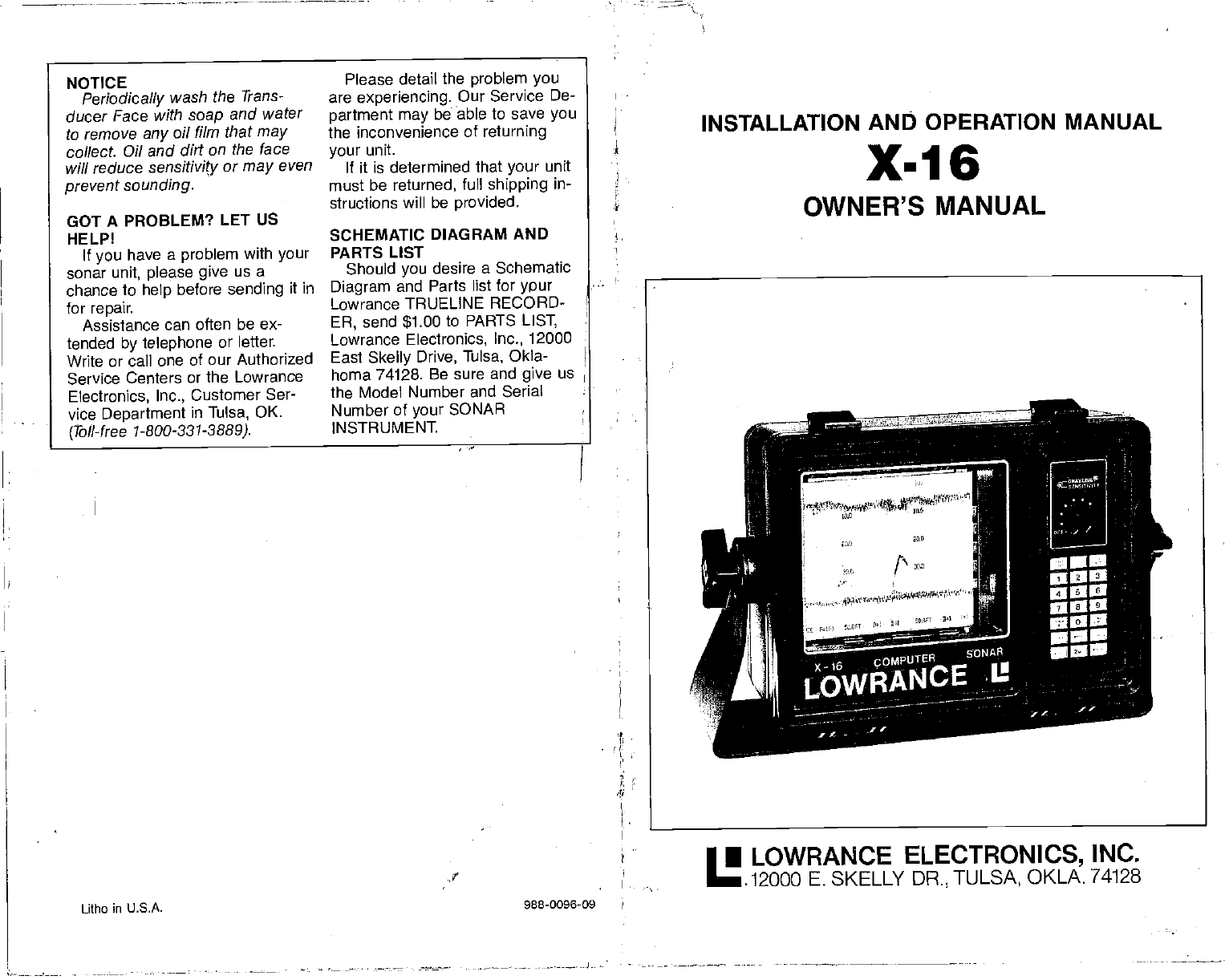
INSTALLATION ANID OPERATION MANUAL
X-16
OWNER'S MANUAL
Litho in U.S.A. 988-0096-09
• LOWRANCE ELECTRONICS, INC.
.12000 E. SKELLY DR., TULSA, OKLA. 74128
NOTICE
Periodically wash the Trans-
ducer Face with soap
and water
to remove any
oil film that may
collect. Oil and dirt on the face
will reduce sensitivity or may
even
prevent
sounding.
Please detail
the problem you
are experiencing. Our Service De-
partment may
be able
to save you
the inconvenience of returning
your unit.
If it is determined that your unit
must be returned, full shipping in-
structions will be provided.
GOT A PROBLEM?
LET US
HELP!
If
you have a problem with your
sonar unit, please give us a
chance to help
before sending it in
for repair.
Assistance can often be ex-
tended by telephone or letter.
Write or call one of our Authorized
Service Centers or the Lowrance
Electronics, Inc., Customer Ser-
vice Department in Tulsa, OK.
(Toll-free 1-800-331-3889).
SCHEMATIC DIAGRAM AND
PARTS LIST
Should you desire a Schematic
Diagram and Parts list for ypur
Lowrance TRUELINE RECORD-
ER, send $1.00 to PARTS LIST,
Lowrance Electronics, Inc., 12000
East Skelly
Drive, Tulsa, Okla-
homa 74128. Be sure and give us
the Model Number and Serial
Number of
your SONAR
INSTRUMENT
PDF compression, OCR, web-optimization with CVISION's PdfCompressor
SURFACE
CLUTTER Algae,
plankton, air bubbles, boat wakes,
and schools of bait fish near the
surface of the water can create
large surface echoes on the paper.
These echoes can extend far
down the paper and interfere with
fish or other
target echoes.
Lowrance has a special feature
called "Surface Clarity Control" or
"5CC" that combats surface clutter
effectively.
THERMOCLINE Junction of dif-
ferent temperature layers. When
the warm and cool temperature
layers meet, a discontinuity in the
water is formed that reflects sonar
signals. This is called a thermo-
dine.
TRANSDUCER The "antenna" of
a sonar unit. This contains a small.
crystal that converts the electrical
energy from
the transducer into
sound energy
and sends it into
the water. It then converts any
sound in its frequency range back
into electrical pulses for the
receiver. Transducers have a van-
ety of styles
including "Thru-Hull"
which bolt thru a hole
drilled in the
hull, "Shoot-Thru-Hull" — epoxied
directly to
the inside of a solid
fiberglass hull with no holes
required, and "Transom Mount" —
bolts directly to the transom of the
hull, either below or flush with the
bottom of the boat.
TRANSPORT ASSEMBLY The
mechanism that holds and pulls
the chart paper from the full paper
roll, past
the stylus, and rolls it up
on the takeup side. It also con-
tains the paper
drive motor and
gear
train. -
2
2
2
3
4
5
5
6
6
7
7
8
8
9
9
-10
10
10
11
1-1
ii
12
13
Specifications 1
Introduction
How it Works
Installation
Power Connections
Transducer Selection
Basic Operation
Sensitivity Control
Clear
Entry
Discrimination
Paper Speed
GRAYLINE
Range
Lower Limit
Upper Limit
Lines
Marker
Scale
Memory/Reset
Feet, Fathoms, Meters
End Of Paper
Zero Adjust
How To Read Graphs
Paper Loading
Stylus Replacement 16
Stylus Belt Replacement 17
Maintenance 17
Troubleshooting 18
ADVANCED OPERATION 18
Surface Clarity
Control (SCC) 18
Suppressor 19
ACCESSORIES
LDT-3000
DIGITAL SURFACE
TEMP
Allows instant visual
wading
of
surface water
temperatures horn
32.0 Ia 99.9
degrees F Includes
heavy 28 foot sensor cable.
DUST COVER
Extra protection lrom the elements.
LSB-200A SWITCH BOX
Allows use ci two
different transducers with
one sonar unit. Weetharpreof switch
activates transducer #1 or
#2.
LSB-201A SWITCH BOX
Allows use ci Iwo soners with
only
one
transducer. Weetherprool switch activates
sonar
#1 or #2.
LXT-11OA TRANSDUCER
EXTENSION CABLE
Ten-fool extension cable far use where a
transducer must be located
beyond the
reach oh the
standard transducer cable.
Sonar unit does not nead returning
when
only
one extension is used.
LKB-2000 TRANSDUCER KICK-UP
BRACKET
Allows THS 1192-20 io be mounted below the
hull on aluminum beets to avoid hull turbulence.
LTB-1
000 TRANSOM
MOUNTING BRACKET
Transom
mounting brscket end
spet specifically designed for use
with V-bottomed boats. Uses
any
Lowrance plastic
bolt-thru-huil
transducer.
LFF-1 02 FISH-N-FLOAT
Two highly vjaibie floats with 100-fool nylon
cord, wraparound lead
sinkers.
LTP-100 FISH-N-TEMP
Portable
temperature and
depth
indicator
far accurate
readings from
30-90 degrees F
end depths to 00 teal.
LPG-605 CHART PAPER
Straight line chart paper, 50 toot
roll, br all
Computer Sonar graph
recorders.
LTC-60 TRANSDUCER
CONNECTOR KIT
Replacas old
slyle
transducer connecter
with new plastic style. Or to repair a
damaged transducer cable.
LPB-192 POWER BOOSTER
Increases the outpul power of the X-150 to
extend the
depth range, better noise
rejection, and increases the ability to
diaptey small detail.
LDT-4000 DIGITAL SURFACE TEMP
New sensor probe allows transom, thru-hut,
or raw water intake
mounting Water
temperature readings trorn 32.0 099.9
degrees F
29
PDF compression, OCR, web-optimization with CVISION's PdfCompressor
the sonar can
separate two tar-
gets
that are 11/2 inches apart.
This
is considered good resolution.
However, if a sonar' pulse length
was 500 micro-seconds,
then the
sonar could only separate targets
that are at least 12 inches apart.
That is why it is so important to
pick a sonar unit that
gives you
the capability to change to narrow
pulse lengths for good resolution.
The X-16 allows pulse lengths
down to 30 micro-seconds or one
inch!
SECOND ECHO A second echo
can appear on the display at
roughly twice the depth of the
actual bottom signal. This is
caused by the transmitted signal
travelling
thru the
water, reflecting
off of the bottom, returning to the
surface, reflecting off the surface,
hitting the bottofti once again, and
finally striking the surface and the
transducer.
Actually,
the sonar sig-
nal can do this many times as you
can see if you are in shallow water
and turn up the sensitivity. Some-
times
three, four, or more echoes
can be displayed.
SENSITIVITY The ability of a
sonar unit
to display targets. If a
unit can display small targets deep
in the water or very
small detail,
then it is said to have high
sensitivity.
A sensitivity control
adjusts the level of the receiver for
different conditions. Also called
gain.
SCALE Depth markings printed
on or near the chart paper
These
can be shown in feet, fathoms, or
meters. Often confused with
Range.
SIGNAL-TO-NOISE
RATIO The
noise level divided by the signal
level in a circuit is expressed by
the term signal to noise ratio. In
sonar,
a high signal to noise ratio
is desirable because less noise
suppression is required and it is
easier for the unit to display only
the true
signals returning from the
targets, rather than a mixture of
signals and noise.
STYLUS This is the fine wire that
does the actual marking on a
graph recorder's
paper. A high
voltage is applied to the stylus
which causes it to burn through
the white outer coating of the
paper, exposing the black carbon
underneath. Use care when han-
dling
a stylus. Never touch it when
the unit is operating.
STYLUS SKIP This is a condition
that occurs when the stylus
doesn't contact the entire surface
of the chart paper. It then leaves
gaps in the record where the
stylus "skip' over spots. Usually,
the problem can be rectified by
removing and bending the stylus
into the proper shape, although
sometimes it is caused by a worn-
out stylus which must then be
replaced.
SUPPRESSOR A Lowrance
exclusive,
patented probess to
eliminate noise from a sonar unit's
display. It works on the principal
that noise pulses are typically
short in duration. By increasing
the transmitters pulse length, and
tracking it with the receiver, the
short noise pulses are cancelled
out.
STYLUS BELT A belt that travels
over two motor driven pulleys. It
typically
has a holder that retains
the stylus and a magnet on the
opposite side that
triggers
thd
transmitter.
Pulse
Alternate Transmit and Print
Paper Save
Print Intensity
Loran Interface
Power Booster
Summary of Commands
Glossary
Accessories
23
24
24
25
26
26
26
29
SPECIFICATIONS
Dimensions (with gimbal mount)
Dimensions (instrument only)
Weight
Chart
Paper
Transmitter
Frequency
Pulse Width (Adjustable)
1 0¼"W x 8¼"H x 65/s"D
12¼"W x 9"H x 65/ct
8.5 pounds
LPG-606
(2) 4" x 50' roll
192 kHz
30 s - 2000 p.s
1600 watts p-p
200 watts RMS
Output Power
Receiver Sensitivity
Chart Speed
Voltage Range
Current Drain
Fuse
—85 db
.10 -3.0 in/mm
10 - 15 vdc
amps, approximately
4 amp
28 1
PDF compression, OCR, web-optimization with CVISION's PdfCompressor
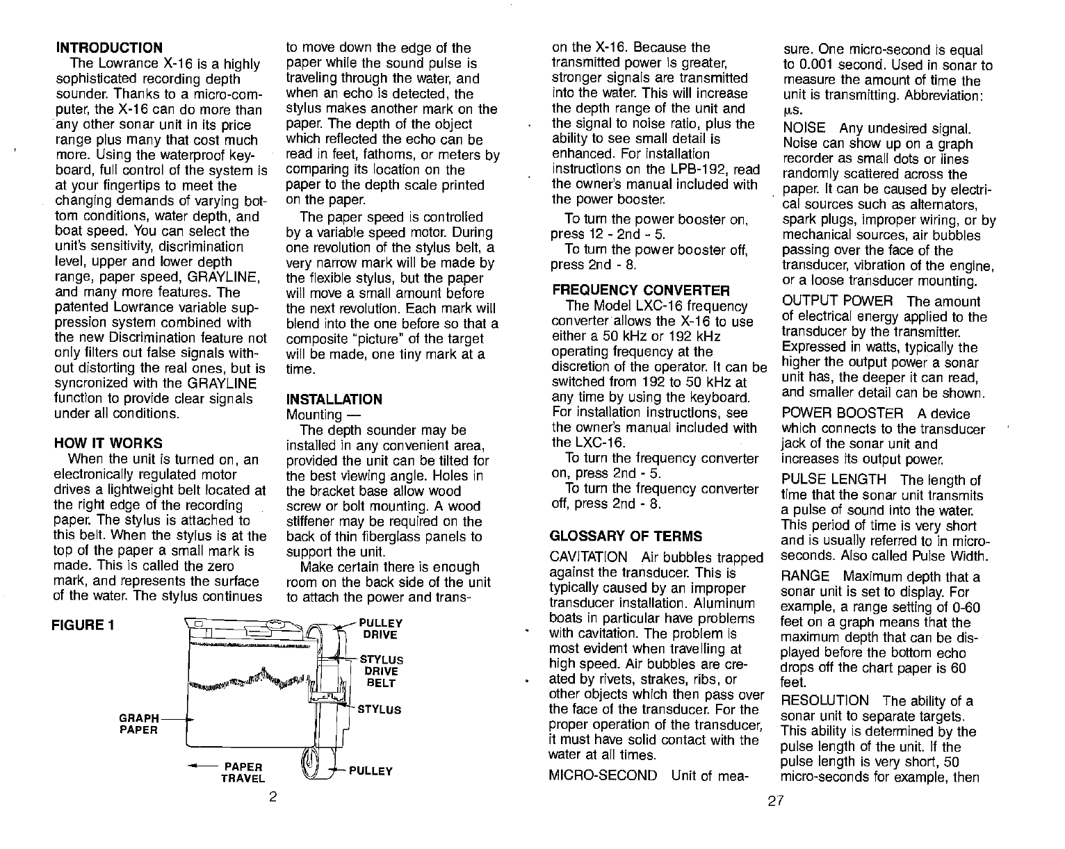
INTRODUCTION
The Lowrance X-16 is a highly
sophisticated recording depth
sounder Thanks to a micro-com-
puter, the X-16 can do more than
any
other sonar unit in its price
range plus many that cost much
more. Using the waterproof key-
board, full control of the system
is
at your fingertips to meet the
changing demands of varying bot-
tom conditions, water depth, and
boat speed. You can select the
unit's
sensitivity, discrimination
level, upper and lower depth
range, paper speed, GRAYLINE,
and many more
features. The
patented Lowrance variable sup-
pression system combined with
the new Discrimination feature not
only filters out false
signals
with-
out distorting the real ones, but is
syncronized with the GRAYLINE
function to provide clear
signals
under all conditions.
HOW IT WORKS
When the
unit is turned on, an
electronically regulated motor
drives a lightweight belt located at
the right edge of the
recording
paper The
stylus is attached to
this belt. When the
stylus is at the
top of the paper a small mark is
made. This is called the zero
mark, and represents the surface
of the water. The stylus
continues
FIGURE 1
GRAPH
PAPER
to move down the edge of the
paper while the sound pulse is
traveling through the
water, and
when an echo
is detected, the
stylus
makes another mark on the
paper. The
depth of the object
which reflected the echo can be
read in feet, fathoms, or meters by
comparing its location on the
paper
to the depth scale
printed
on the paper.
The
paper speed is controlled
by a variable speed motor During
one revolution of the stylus
belt, a
very
narrow mark will be made by
the flexible stylus, but the paper
will move a small amount before
the next revolution. Each mark will
blend into the one before so that a
composite picture" of the target
will be made, one tiny mark at a
time.
INSTALLATION
Mounting —
The
depth sounder may be
installed in any
convenient area,
provided
the unit can be tilted for
the best viewing angle. Holes in
the bracket base allow wood
screw or bolt mounting.
A wood
stiffener may be required on the
back of thin fiberglass panels
to
support the unit.
Make certain there is enough
room on the back side of the unit
to attach the power and trans-
PULLEY
DRIVE
-STYLUS
DRIVE
BELT
• STYLUS
PULLEY
on the X-16. Because the
transmitted power is greater,
stronger signals are transmitted
into the water. This will increase
the depth range of the unit and
the signal to noise ratio, plus the
ability to see small detail is
enhanced. For installation
instructions on the LPB-1
92, read
the owner's manual included with
the power booster.
To turn the power
booster
on,
press
12- 2nd -5.
To turn
the power
booster
off,
press
2nd - 8.
FREQUENCY CONVERTER
The Model LXC-16 frequency
converter allows the X-16 to use
either a 50 kHz or 192 kHz
operating frequency at the
discretion of the
operator. It can be
switched from 192 to 50 kHz at
any
time by using
the keyboard.
For installation instructions, see
the owner's manual included with
the LXC-16.
To turn
the frequency converter
on, press 2nd - 5.
To turn
the frequency converter
off, press 2nd - 8.
GLOSSARY OF TERMS
CAVITATION Air bubbles trapped
against the transducer. This is
typically
caused by an improper
transducer installation. Aluminum
boats in particular have problems
with cavitation. The problem is
most evident when
travelling at
high speed. Air bubbles are cre-
ated by rivets, strakes, ribs, or
other
objects which then pass
over
the face of the transducer. For the
proper operation of the transducer,
it must have solid contact with the
water at all times.
MICRO-SECOND Unit of mea-
sure. One micro-second is equal
to 0.001 second. Used in sonar to
measure the amount of time the
unit is transmitting. Abbreviation:
W5.
NOISE Any undesired
signal.
Noise can
show up on a graph
recorder as small dots or lines
randomly scattered across the
paper. It can be caused by electri-
cal sources such as alternators,
spark plugs, improper wiring, or by
mechanical sources, air bubbles
passing over the face of the
transducer,
vibration of the engine,
or a loose transducer mounting.
OUTPUT POWER The amount
of electrical energy applied to the
transducer by the transmitter.
Expressed in wafts, typically
the
higher the output power a sonar
unit
has, the deeper it can
read,
and smaller detail can be shown.
POWER
BOOSTER A device
which connects to the transducer
jack of the sonar unit and
increases its output power.
PULSE LENGTH The length of
time that the sonar unit
transmits
a pulse of sound into the water
This
period of time is very short
and is usually referred to in micro-
seconds. Also called Pulse Width.
RANGE Maximum depth that a
sonar unit is set to display.
For
example, a range setting of 0-60
feet on a graph means that the
maximum depth that can be dis-
played before the bottom echo
drops off the chart paper is 60
feet.
RESOLUTION The
ability of a
sonar unit to separate targets.
This ability is determined by the
pulse length of the unit. If
the
pulse length is very short, 50
micro-seconds for example, then
27
2
PDF compression, OCR, web-optimization with CVISION's PdfCompressor
be used to help alleviate this
condition.
LORAN-C
INTERFACE
A remarkable advantage of the
X-16 is its
ability
to print
Loran-C
coordinates in either
Time Differen-
ces (ID's) or Latitude and Longi-
tude. (NOTE:
The
X-16 has been
designed to use
only the Lowrance
Loran-C
receiver.)
To connect the
Loran to the X-16, simply splice
the
white and black
wire on the X-16's
power
cable to the
white and black
wire on the Loran-Cs
power
cable.
(See Figure 2 on page 3.) After the
proper connections have been
.i.:: I—
I1iI
24.0 ——I
p6.0
—— —
26.0
B.0— 48.0—
4
60.Ofl—
Figure 46
made, turn on both the Loran and
the X-16. After the Loran has
acquired
the
signals, press
2nd - 0.
The Loran coordinates will imme-
diately be printed vertically
down
the paper. Either Latitude and
Longitude or Time Differences
(TD's)
will be printed on the paper
depending on the mode the Loran
is in. If 2nd - 0 is pressed and no
Loran is connected, the unit will
stop pulling paper
and printing for
approximately four seconds.
POWER BOOSTER
A power booster, Model
LPB-192, is available that will
increase the transmitter's output
power of the X-16. It can be
turned on or off by the keyboard
26
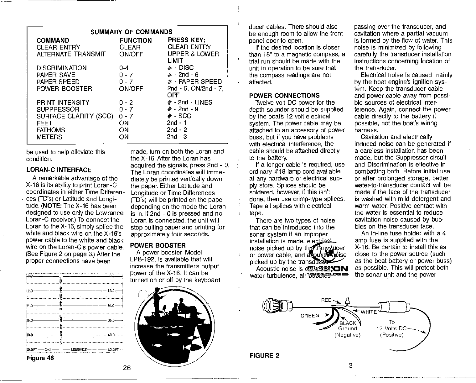
ducer cables. There should also
be enough room to allow the front
panel door to open.
If the desired location is closer
than 18" to a magnetic compass, a
trial run should be made with the
unit in operation to be sure that
the compass readings are not
affected.
POWER CONNECTIONS
Twelve volt DC power for the
depth sounder should be supplied
by the boat's 12 volt electrical
system. The power cable
may be
attached to an accessory or power
buss, but if you have problems
with electrical interference, the
cable should be attached directly
to the battery.
If a longer
cable is required, use
ordinary #18 lamp cord available
at any
hardware or electrical sup-
ply store. Splices should be
soldered, however, if this isn't
done, then use crimp-type splices.
Tape all splices with electrical
tape.
There are two types
of noise
that can be introduced into the
sonar system if an improper
installation is made, electrical
noise picked up by the transducer
or power cable, and acoustic noise
picked up by the transducer.
Acoustic noise is caused by
water turbulence, air bubbles
FIGURE 2
3
passing over the transducer, and
cavitation where a partial vacuum
is formed by the flow of water. This
noise is minimized by following
carefully the transducer installation
instructions concerning location of
the transducer.
Electrical noise is caused mainly
by the boat engine's ignition sys-
tem. Keep the transducer cable
and power cable away from possi-
ble sources of electrical inter-
ference. Again, connect the
power
cable directly to the battery if
possible, not the boat's wiring
harness.
Cavitation and electrically
induced noise can be generated if
a careless installation has been
made, but the Suppressor circuit
and Discrimination is effective in
combatting both. Before initial use
or after prolonged storage, better
water-to-transducer contact will be
made if the face of the transducer
is washed with mild detergent and
warm water. Positive contact with
the water is essential to reduce
cavitation noise caused by bub-
bles on the transducer face.
An in-line fuse holder with a 4
amp fuse is supplied with the
X-1 6. Be certain to install this as
close to the
power source (such
as the boat battery or power buss)
as possible. This will protect both
the sonar unit and the
power
SUMMARY OF COMMANDS
COMMAND
CLEAR ENTRY
ALTERNATE TRANSM IT
FUNCTION
CLEAR
ON/OFF
DISCRIMINATION
PAPER SAVE
PAPER SPEED
POWER BOOSTER
PRESS KEY:
CLEAR ENTRY
UPPER & LOWER
LIMIT
0-4
0-7
0-7
ON/OFF
- DISC
- 2nd - 6
- PAPER SPEED
2nd - 5, ON/2nd - 7,
OFF
PRINT INTENSITY
SUPPRESSOR
SURFACE CLARITY (SCC)
FEET
0-2
0-7
0-7
FATHOMS
METERS
ON
- 2nd - LINES
- 2nd - 9
- SCC
ON
ON
2nd - 1
2nd - 2
2nd - 3
OFE
(Negative)
PDF compression, OCR, web-optimization with CVISION's PdfCompressor
cable in the event a short occurs.
Crimp
connectors are supplied to
attach the fuse holder to the
power cable. The red wire in the
power cable is the
positive con-
ductor The black wire is the
ground or negative conductor.
The graph is protected from
accidental polarity reversals and
no damage will occur if the wires
are reversed. The unit will not
operate until the proper polarity
is
applied.
FIGURE 3
When
installing the power
cable,
you will find two extra wires com-
ing
from the power
cable. The
green one is for an optional Power
Booster and the other
white wire
is for connection to a Loran C
receiver If neither of these fea-
tures are going
to be used, tape
the ends of the
green
and white
wires so that
they
cannot short
Refer to the Advanced Operation
section for more information on
these wires.
TRANSDUCER SELECTION
Lowrance offers you the choice
of transducers with either an 8 or
20 degree cone
angle that will
interchange with any
of our 192
kHz sonar units. In other
words,
any Lowrance sonar instrument
can be used with any
Lowrance
transducer of the same frequency
without retuning of any kind, and
no loss of performance. However,
the use of any
other manufac-
turer's transducer will result in a
loss of performance.
Now you
can select the trans-
ducer design and cone angle
to
best fit your specific needs. Gen-
erally, wide cone
angle transdu-
cers
(20 degrees) are ideally
suited for operating in shallow
water or at medium depths. The
20 degree cone
angle
allows
you
to see more of the underwater
world. In 15 feet of water the 20
degree cone covers an area of the
bottom thath about 6 feet across.
The 8 degree transducer covers
only about a 2 foot circle.
way
to slow the chart paper The
chart below gives the range
of
the
Paper Save function and the
amount that each level slows the
paper.
To enable the Paper Save
function, simply press the level of
paper
save desired, then 2nd,
then 6. The paper should slow
immediately. For example,
suppose you
wish to slow the
paper
down to 1/4 its present
speed. Press 3 - 2nd - 6 and the
paper
will now be traveling four
times slower than its previous
speed.
When the Paper Save function
is enabled, the X-16 will print
PSV= and the level of paper save
that you
selected. For example, in
our previous example the Paper
Save value was 3. The X-1 6 will
print PSV=3 on the bottom line of
the chart paper (See Figure 45.)
- — -- 1
Lao
34.0 - - -
360
48,0
•
60.OFT— rL LOUPAITCE PSU3
Figure 45
The Paper Save function can
also be used with the Alternate
Transmit and Print function which
will cut
any Paper Save
speed in
half. This gives fourteen different
paper speeds selectable by the
operator.
To disable the Paper Save
function, simply press 0 - 2nd - 6,
and the paper will speed up.
PRINT INTENSITY
Three levels of print intensity are
provided for different conditions.
The stylus printing can be
adjusted to print lighter or darker
by using the Print Intensity mode.
When the X-16 leaves the factory,
the Print Intensity is set to level 1.
To change this setting, press the
level of intensity desired, from 0 to
2 (0 is lightest, 2 is darkest) and
then press 2nd - LINES.
For example, if the stylus is
printing too light, press 2 - 2nd -
LINES and the markings on the
chart paper should become
darker
This feature is useful when a
stylus becomes old. By using the
'2" level or darkest level, the
printing can
improve. If, when
using very
slow paper speeds, the
record has much overprint due to
multiple stylus strikes in a small
area, the '0" or lightest level can
PAPER SAVE
LEVEL CHART SPEED REDUCED TO
1 1/2
2 1/
3 1/4
4 1/5
5 1/6
6 1/
7 1/
FIGURE 4
Co,e
AnSI. I
O.pth
L. 7ft lIlt I
II" 4 I
III' 11 13
1240 28 7' I
50'
100'
150'
200'
8°at3db
4 25
PDF compression, OCR, web-optimization with CVISION's PdfCompressor
keyboard
the initial pulse length
desired and then press the PULSE
key. For example, to set the initial
transmit pulse length to 1 00 micro-
seconds, press 1 - 0 - 0 - PULSE.
This will override the micro-com-
puter's selection and set the initial
transmitter pulse length
to 100
micro-seconds. P
=
100 will be
printed at the bottom of the paper
to signify that
the entry has been
confirmed. (Note: When an initial
transmit pulse length is set, this
length will be fixed for all depth
settings until changed.)
To return
control back to the
micro-computer, press 0 - PULSE
and the micro-computer will select
the initial pulse length.
ALTERNATE
TRANSMIT AND
PRINT
When using the X-16 in deep
water, or if
you
wish to simply
conserve paper, it may
be desir-
able to slow the paper speed even
more than the automatic system
allows. However, when doing so,
you may get over print" or very
dark, heavy printing over an area
that is difficult to read. Much detail
can also be lost due to this.
A feature that is available on the
X-16 is the Alternate Transmit and
Print function which, when acti-
vated, causes the stylus to print
every other revolution instead of
every revolution. This accom-
plishes four
things:
1. Since the stylus only prints
every other revolution, the
recorded information doesn't have
the "over print" problem, therefore
good records are attainable at
slower paper speeds. Also, the
scale numbers are spread out
more, making them more legible.
2. Reduces the possibility of
24
"wrap-around". This is the undesir-
able occurrence of the second or
third bottom echo
printed on the
paper at the top or middle of the
page. Many times this can inter-
fere with fish or other
targets
that
you
wish to see.
3. Reduces the reverberation
effect. This happens mainly on
lower
frequency units, but it can
happen on higher frequency mod-
els. Reverberation is heavy,
scattered noise marks caused by
the transmitted signal becoming
trapped between the surface and
the
bottom, usually scattered in
heavy plankton layers or baitfish
schools. This causes a great many
lines to be printed on the page. By
enabling the Transmit and Print
function, the transmitter is trig-
gered only half as many times as
normal, puffing less energy into
the water (same amount of trans-
miller power, just not as often)
which reduces the amount of
noise seen.
4. Divides the paper speed by
two. A significant amount of paper
can be saved by using the Alter-
nate Transmit and Print feature.
To turn this feature on, simply
press the 2nd key, then press the
"4" key. The paper speed will
immediately slow
down, signifying
that the function is enabled.
To turn the Alternate Transmit
and Print feature off, simply press
the 2nd key and then press the
"7" key. The paper speed will
immediately speed up, signifying
that the function has been turned
off.
PAPER SAVE
Although the Alternate Transmit
and Print function will slow the
paper speed, the
Paper Save
function is an even more powerful
Thus, you would use a 20
degree transducer when looking
for fish or strubture,
to easily
find
drop-offs or reefs, and to see fish
that are around you . . . not just
below you. However,
the 20
degree transducer won't
penetrate
to greater depths as well as the 8
degree transducer, nor will it show
a sharp drop-off as well. In a
deep-water environment (100 feet
or deeper) or where you're
looking
at sharp drop-offs, the narrow
cone angle can sometimes be
more desirable because it can
more accurately detect the loca-
tion of the drop-off without
displaying the fish. In deep water,
with the sound energy being con-
centrated in a smaller area, the 8
degree transducer can reach to
greater depths.
Both the 8 degree and the 20
degree transducers give accurate
bottom readings, even though the
bottom signal is much wider on
the 20 degree model because
you
are seeing more of the bottom.
Remember,
the shallow edge of
the signal shows you the true
depth. The rest of the signal tells
you whether
you
are over rocks,
mud, dropoffs, etc.
Thanks to the LSB-200A trans-
ducer switch
box, you can have
the best of both worlds. By install-
ing
the LSB-200A near the
operator, both a 20 degree and an
8 degree cone angle transducer
may be mounted on a boat and
connected to the switch box. A
cable from the switch box is then
connected to the X-16. Now
either transducer may
be used as
conditions dictate. Use the 20
degree transducer when in shal-
low to medium depths and then
switch to the 8 degree transducer
5
when in deep water or when you
need just navigation information.
Salt water boats need to have
the transducer
painted with a thin
coat of anti-foulant paint
to prevent
organisms from growing. If un-
checked, barnacles and other
marine growth will cause a
decrease in the transducer's sen-
sitivity. Do not use a metal based
anti-foulant paint
as it will de-
crease the transducers sensitivity
also. There are special paints on
the market specifically designed
for transducers and are carried
by
most marine dealers.
BASIC OPERATION
On-Off and Sensitivity Control —
Rotate the Sensitivity knob
clockwise to turn the unit on. The
Sensitivity knob works much like
the volume control on a radio, that
is, weaker signals will be detected
with higher settings
of the knob.
When cruising, or at other times
when
just simple bottom contour
information is desired, the Sen-
sitivity setting can be low. In deep
water or over soft, muddy bottoms,
(which produce weak echoes), the
setting will have to be higher.
When high Sensitivity settings
are used, a second bottom echo
will appear. This is normal and is
caused by the returning signal
reflecting off the surface of the
water, making a second trip to the
bottom and back.
If detailed information about
brush piles, individual fish, or the
thermocline is desired, the Sen-
sitivity
knob should be rotated to
approximately the ¾ point. Refer
to the illustrations on page 6 to
see what effect the Sensitivity
control setting has on the recorded
information.
PDF compression, OCR, web-optimization with CVISION's PdfCompressor
Recording individual fish with an
"arched" signature
can usually be
accomplished at trolling speed
with the Sensitivity
knob at the ¾
point, or higher. Refer to the
section 'Arched
Signatures" for
more information about this impor-
tant function of the recorder.
12.0
244 / b'240
36,0 360
480
FIGURE 6
CLEAR ENTRY
The CLEAR ENTRY key is used
when a mistake has been made
when entering a command to the
unit. If, for example, you wish to
set the lower depth limit to 500
feet, and by accident, you press
509. BEFORE you press the
LOWER LIMIT key, you can press
the CLEAR ENTRY key which
erases the mistake, and allows
you to re-enter the correct
command.
DISCRIMINATION
Noise pulses are the largest
complaint most often received
about sonar units. Lowrance has
had the patented Suppression
system for many years which is
quite effective at eliminating noise
from the display.
The only draw-
back to the Suppression system is
that it increases the transmitter's
pulse length which
decreases res-
olution and causes
targets that are
close together to merge into one
"blob" instead of two distinct
images.
Discrimination is a program
installed in the X-16's micro-
processor that enables it to
process the output
from the
receiver, determine which signals
are noise and eliminate them, then
print only the legitimate echoes.
Using this concept, the transmit-
ted pulse does not have to be
increased, therefore records with
high resolution and high noise
immunity can be achieved.
Discrimination is interlaced with
Suppression, however, and some
suppression is used when higher
levels of Discrimination are
chosen. For a complete explana-
tion of Suppression and
Discrimination, see the Advanced
Operation section entitled "Sup-
pression". There are five levels of
Discrimination that can be used.
(0) is the lowest level whereas the
highest value (4) is the stron9est
level and should be used only
when severe noise is present.
Another advantage of Discrimi-
nation is its ability to filter out
interference from other depth
sounders. This allows the simul-
taneous operation of a digital
depth sounder and the X-16. Turn
both units on. If interference from
Suppressor level by using the
Suppressor control at any level
above 3. The Suppressor control
will override the automatic selec-
tion
that Discrimination chose. If a
suppression level greater than 0 is
selected by the operator, then the
X-16 will print an "F' after the
Discrimination level, For example if
the Discrimination
level is 1 and
the Suppressor level is set (or
"fixed") to 3, then the
X-16 will
print "D
=
1 F'. This is a reminder
that some level of suppression is
in use. (See Figure 43.)
- —
lab - 12.0
24.0
- - 84,0
36.0
4S.0—
60,0FT——B1F--L0URAr1CE 60
OFT-j
FIGURE 43
PULSE
In the Suppressor section of this
manual, we explained the relation-
ship between pulse length
and
target separation. As pulse length
increases, target separation, As
pulse length increases, target sep-
aration or resolution is degraded
but deep water penetration
improves. However,
if the pulse
width is decreased, resolution
becomes much better. The
X-16
allows you to take advantage of
this fact by making it possible to
override the initial transmitter
pulse length setting from what
the
micro-computer selects according
to the Lower Limit.
The initial transmitter pulse
length can be set from 30 ps to
1700 ps by entering it on the
keyboard. By setting the initial
transmitter pulse with to 100 jis, a
three inch resolution is obtained,
50 ps equivalent
to an inch and a
half, and 30 ps initial transmit
pulse
length is equal to one inch
resolution! No other graph
recorder in the market today
can
give you this feature. After
setting
the initial transmitter pulse length,
the Discrimination
function can be
used to eliminate noise and still
have good resolution.
The X-16 will display the initial
transmitter pulse length at the
bottom of the paper when
you
over-ride the micro-computer.
To
distinguish the initial transmitter
pulse from the other information
printed on the paper,
the graph
will print P=100 (if
the pulse
is set
to 100 micro-seconds.)
A 50 ps
initial pulse length
would be dis-
played as P=50. (See Figure 44.)
NOTE: If a
pulse length 110
micro-seconds or less is chosen
by the operator,
the Suppressor is
disabled. Also, less than max-
imum power is transmitted when
the pulse length is less than 100
micro-seconds.
To set the initial transmitter
pulse length, simply press on the
FIGURE 5 SENSITIVITY: TOO LOW
0.0 0
-' L\ 4
SENSITIVITY: PROPER SETTING
Figure 44
6 23
PDF compression, OCR, web-optimization with CVISION's PdfCompressor
selected, the transmit
pulse length
would be: 525 + 200 = 725
micro-seconds. We added the ini-
tial transmit
pulse of 525 micro-
seconds which is listed in the
initial transmit
pulse
chart, to 200
micro-seconds, which is Sup-
pressor level 3, according to the
Discrimination - Suppressor chart.
So the total initial transmit
pulse
length is 725 micro-seconds. Now,
if we want,
we can increase the
PAPER SPEED CONTROL
This key adjusts
the
speed of
the chart paper. Its range is 0 to 7.
When the X-16 is first turned
on,
the paper speed is set to level 5.
This setting is good for detailed
graphs, in shallow to medium
depths when trolling.
It will show proper fish arches at
low speeds and keeps high speed
information from being com-
pressed. The paper speed should
be turned down when using
the
unit in deep water. This will pre-
vent gaps
from appearing in the
record. In fact, the microcomputer
will automatically slow the max-
imum speed of the chart paper
when operating in deep water.
To change the speed of the
chart paper, simply press the new
level desired, from 0 to 7, then
press the PAPER SPEED key. The
paper speed should change
immediately.
Remember, if
gaps in the record
appear,
turn the
paper speed
down until a solid record is
achieved. The paper speed may
also be slowed when not looking
for fish or to simply conserve
paper. If heavy printing, or "over-
strike" occurs, turn the paper
speed up. Overstrike happens
when the paper
moves too slow
past the stylus, which causes the
stylus to print over a large portion
of the previous mark. This makes
heavy, black marks on the chart
paper. Usually, the easiest
way to
solve this problem is to turn the
paper speed up. However,
Alter-
nate Transmit and Print or the
Paper Save function listed in the
Advanced Operation section in this
manual, may help also.
GRAYLINE CONTROL
The GRAYLINE function can be
SUPPRESSOR LEVEL INITIAL TRANSMIT PULSE INCREASE
(micro-seconds)
0 AUTOMATIC
1 0
2 100
3 200
4 330
5 450
6 600
7 800
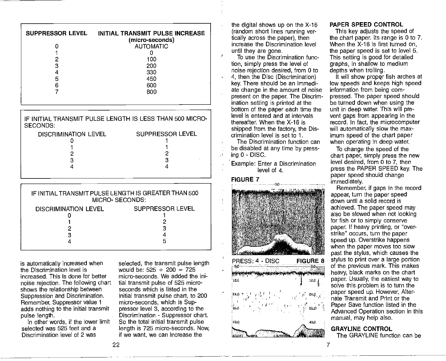
the digital shows
up on the X-16
• (random short lines running ver-
tically across the paper), then
increase the Discrimination level
until they are gone.
To use the Discrimination func-
tion, simply press the level of
noise rejection desired, from 0 to
4, then the Disc (Discrimination)
key. There should be an immedi-
ate change in the amount of noise
present on the paper. The Discrim-
ination setting is printed at the
bottom of the paper
each time the
level is entered and at intervals
thereafter. When the X-16 is
shipped from the
factory,
the Dis-
crimination level is set to 1.
The Discrimination function can
be disabled at any
time by press-
ingO-DISC.
Example: Enter a Discrimination
level of 4.
IF INITIAL TRANSMIT PULSE LENGTH IS LESS THAN 500 MICRO-
SECONDS:
DISCRIMINATION LEVEL SUPPRESSOR LEVEL
0 1
1
2 2
3 3
4 4
IF INITIAL TRANSMIT PULSE LENGTH IS GREATER THAN 500
MICRO- SECONDS:
DISCRIMINATION LEVEL SUPPRESSOR LEVEL
0 1
1 2
2 3
3 4
4 5
FIGURE 7 ----0.0--—
is automatically increased when
the Discrimination level is
increased. This is done for better
noise rejection. The
following chart
shows the relationship
between
Suppression and Discrimination.
Remember,
Suppressor value 1
adds nothing to the initial transmit
pulse length.
In other
words, if the lower limit
selected was 525 feet and a
Discrimination level of 2 was
PRESS: 4 - DISC FIGURE 8
—nfl ———-— — — — ——__________
-
12.0 • 12.0
24.0 fl' --
• ' • -•
48,0
22 7
PDF compression, OCR, web-optimization with CVISION's PdfCompressor
used to outline the bottom contour
which
might
otherwise be hidden
beneath trees and brush; it can
also give clues to the composition
of the bottom. A hard bottom
returns a very strong signal caus-
ing a wide gray line. A soft, muddy
or weedy bottom returns a weaker
signal which is emphasized
with a
narrow gray line. Do not advance
the control too far or it will gray
line on the target completely,
showing no black, which makes
the target
difficult to see.
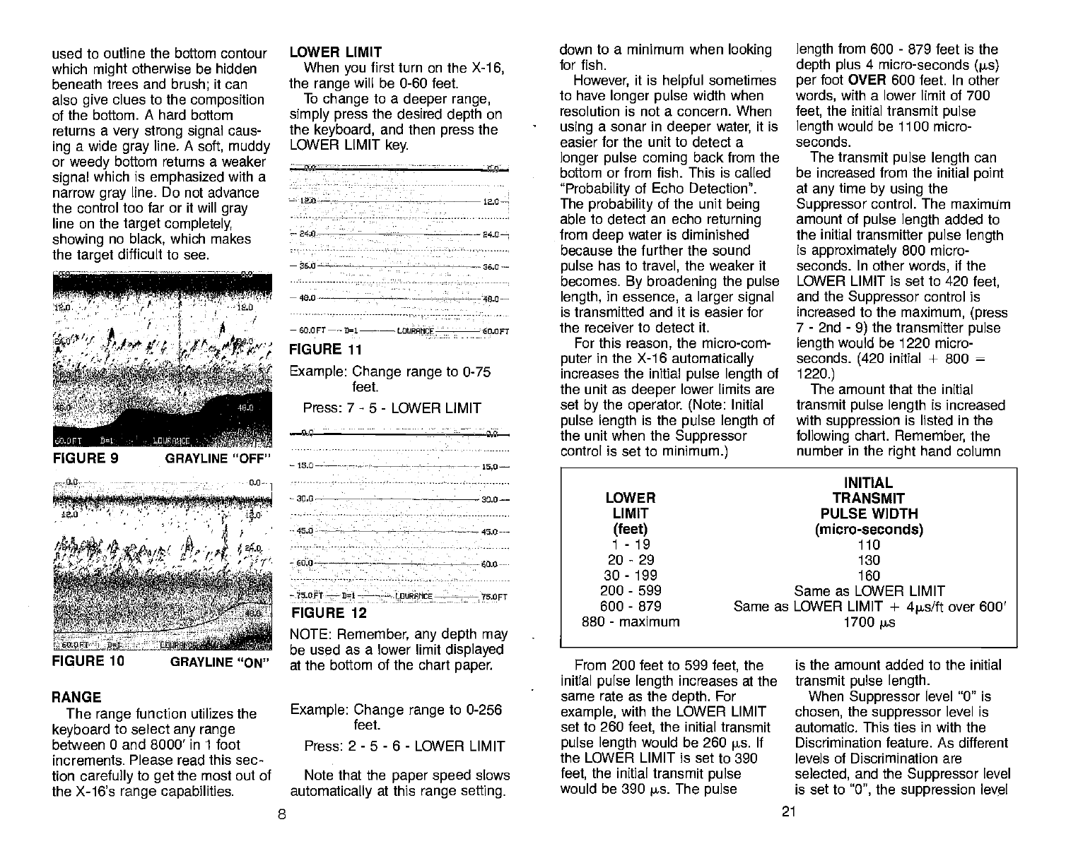
RANGE
The range
function utilizes the
keyboard to select
any range
between 0 and 8000' in 1 foot
increments. Please read this sec-
tion carefully
to get the most out of
the X-16's range capabilities.
LOWER LIMIT
When you first turn on the X-1
6,
the range will be 0-60 feet.
To change to a deeper range,
simply press the desired depth on
the keyboard, and then press the
LOWER LIMIT
key.
NOTE: Remember, any depth may
be used as a lower limit displayed
at the bottom of the chart paper.
Example: Change range to 0-256
Press: 2-5 -6- LOWER LIMIT
Note that the paper speed
slows
automatically at this range setting.
down to a minimum when looking
for fish.
However,
it is helpful sometimes
to have longer pulse
width when
resolution is not a concern. When
using a sonar in deeper
water, it is
easier for the unit to detect a
longer pulse coming back from the
bottom or from fish. This is called
"Probability of Echo Detection".
The probability of the unit
being
able to detect an echo returning
from
deep water is diminished
because the further the sound
pulse has to travel, the weaker it
becomes. By broadening the pulse
length, in essence, a larger signal
is transmitted and it is easier for
the receiver to detect it.
For this reason, the micro-com-
puter
in the X-1 6 automatically
increases the initial pulse length of
the unit as deeper
lower limits are
set
by the operator. (Note: Initial
pulse length is the pulse length of
the unit when the Suppressor
control is set to minimum.)
From 200 feet to 599 feet, the
initial pulse length increases at the
same rate as the depth. For
example, with the LOWER LIMIT
set to 260 feet, the initial transmit
pulse length would be 260 p5. If
the LOWER LIMIT is set to 390
feet, the initial transmit
pulse
would be 390 ps. The
pulse
length from 600 - 879 feet is the
depth plus 4 micro-seconds Qis)
per foot OVER 600 feet. In other
words, with a lower limit of 700
feet, the initial transmit
pulse
length would be 1100 micro-
seconds.
The transmit
pulse length can
be increased from the initial point
at any
time
by using the
Suppressor control. The maximum
amount of pulse length added to
the initial transmitter pulse length
is approximately 800 micro-
seconds. In other
words, if the
LOWER LIMIT is set to 420 feet,
and the Suppressor control is
increased to the maximum, (press
7 - 2nd - 9) the transmitter pulse
length would be 1220 micro-
seconds. (420 initial + 800 =
1220.)
The amount that the initial
transmit
pulse length is increased
with suppression is listed in the
following chart. Remember, the
number in the right hand column
is the amount added to the initial
transmit pulse length.
When Suppressor level 0" is
chosen, the suppressor level is
automatic. This ties in with the
Discrimination feature. As different
levels of Discrimination are
selected, and the
Suppressor level
is set to 0", the suppression level
— 12.0— 120—
—240 -
—240-—-
—360—--———- — 260—
—400--—— ——480—
feet.
—
60.OFT—— 3=1—-—— LOIJRAMCE - - - 60.OFT
FIGURE 11
Example: Change range to 0-75
Press: 7 - 5 - LOWER LIMIT
FIGURE 9 —15.0—--— _——-— 15.0—
—
30.0 - ________—---— 30.0——
45.0 - — ——-—450
600——-— ——--—-— — —600
—75 OFT —
111
— —— — LD4RFMCE——-— 75 OFT
FIGURE 12
FIGURE 10 GRAYLINE "ON"
INITIAL
LOWER TRANSMIT
LIMIT PULSE WIDTH
(feet) (micro-seconds)
1-19 110
20-29 130
30-199 160
200
-
599 Same as LOWER LIMIT
600
-
879 Same as LOWER LIMIT + 4ps/ft
over 600'
880
-
maximum 1700
j.s
feet.
8 21
PDF compression, OCR, web-optimization with CVISION's PdfCompressor
0:THH
t; H'
j/ 'yL
j/'11 if,
FIGURE 40
graph record becomes coarse and
the
ability
to separate fish from the
bottom or from other fish will be
decreased. (See Figure 41 & 42.)
Therefore, the lower
the
suppression setting, the better.
Increase the Suppressor setting
only as far as necessary to
remove the erratic, unwanted
noise marks. Most of the time at
low or trolling speeds, no
suppression will be necessary.
To use the Suppressor, simply
press the desired amount of
suppression desired, from 0 to 7,
and then press the 2nd key and
the 9 key. For example, if you
wanted to increase the
suppression level to 5, then you
would press: 5 - 2nd - 9, in that
order. When any Suppressor level
other than 0 is chosen, the level is
printed on the bottom line of the
chart paper. For example, if the
suppressor level is set to 5, then
the X-16
will print: SUP=5.
The only disadvantage to this
system is that resolution, or the
ability to separate targets, is
diminished when the pulse length
is increased. A 200 is (micro-
second) transmitter pulse length
used on the X-16 when power is
first
turned
on, will allow
the unit
to display two fish or targets that
are only 6 inches apart. In other
words, if two fish that are 6 inches
apart
are displayed on the
graph
paper, they
will show up as two
separate arches when the trans-
mitter is operating with a 200 ps
pulse
length. Now, if we increase
the transmitter's pulse length to
400 ps, (by increasing the Sup-
pressor) those
same two fish
arches will blend together and
show up as one fish or
possibly even a 'blob" on the
paper.
With a 400 is transmit
pulse
width, those
same two fish will
have to be at least 12 inches apart
before they
will show up as two
separate arches on the
graph.
This is why it is important
to leave
the Suppressor control turned
20
256.OFT 01 LOIJRAIICE 256.OFT
FIGURE 13
UPPER LIMIT
Many times it is desirable to
expand a section of the area that
is displayed on the graph recorder
to show more detail. This is made
possible by the X-16 to show
segments of the underwater world
by using the UPPER LIMIT func-
tion. Using the UPPER LIMIT key
allows you to display any depth
range at the top of the chart
paper.
Example: Turn on unit and set
range
to 20 - 60 feet.
Press: 2 - 0 - UPPER LIMIT
Press: 6 - 0 - LOWER LIMIT
20.0 - —-- ---20,0 -:
23.0-- — —-----—- - -28.0
36.0
——--- — -
36.0
44.0-— --—— —-— 44.0
52.0 —---— —
66.2 61.2-—-
_ —— —- 66.6- -
?2.OFT
--- 31-— —-
LPMCE — 72.PFT—
FIGURE 15
The Upper and Lower Limits
can be used in various combina-
tions to show segments from the
surface to the bottom and any-
where in between. A one foot
segment of the depth can be
displayed at any
time, if desired.
Representative samples
of chart
paper
are shown in the back of
this manual.
If you
wish to display your depth
settings
at any
time,
simply press
the 2nd key and then the SCALE
key. The current range
will be
printed on the paper immediately.
This will not change the
depth
selling.
NOTE:
Although the maximum
lower limit of the
depth range is
8000 feet, the actual depth that
the X-16 will reach is dependent
on water conditions, bottom condi-
tions, and the quality of the
transducer installation. Typically,
the X-16 will reach a depth of
approximately 1000 feet without a
power booster. You may get more
or less depending on conditons.
LINES
When the X-16 is first turned
on,- depth lines will be printed on
the paper. If you desire to turn the
Lines
off, press the LINES key. To
turn the lines back
on, press the
LINES key again.
-on ___0.0
l;f 'F'?Ii1irr;ç, flr!il..6!r1j!jI!!!I
0.0 l,O — -
-51.2 —- 51.2— —- -- 50.4 -
102.4—--— —-—--——--—-——— 102.4
653.6 —— 153.6--
FIGURE 42 SIJPPRESSION:TOOHIGH
— —-- —— 204.0 --
-. —-,- \...
-' - , ' ekF
'4,':
$'SWC
c
- r ' ''1 ''
4rzrr—" OURAIICE
FIGURE 41 PROPER SETFING I.
60.6 FT
——
21
----——----
LOURAIICE —- -—--
60.0 FT
-
FIGURE 14
Example: Set range to 45 - 72
feet.
Press: 4 - 5 - UPPER LIMIT
Press: 7 - 2 - LOWER LIMIT
9
PDF compression, OCR, web-optimization with CVISION's PdfCompressor
12.0
24.0
26.0
49.0
60.0 Ft 21 L0IJRAHCE
FIGURE 16
MARKER
An event marker function is
included in the X-1 6 so that events
may be marked when desired. To
use the
marker, simply press the
MARK key and a vertical line will
be displayed across the entire
page. Hold the MARK key down
and a vertical line will be printed
for as long as the
key is held
down.
Example:
Press: MARK
SCALE
The numbers that indicate the
depth or scale
may be deleted if
desired. Pressing the SCALE key
once will stop
the printing of the
scale numbers. The scale may
be
displayed again by pressing the
SCALE key.
Remember, the scale may
be
displayed at any time by pressing
the 2nd key and then the SCALE
key.
Example:
Press: SCALE
—
FIGURE 18
MEMORY/RESET
The Lowrance X-16 has an
internal battery
that keeps power
supphed to the memory circuits
even when
the
power switch is
turned off. The power cable may
be unplugged from the unit and
the X-16 will still remember the
last settings that were in effect
when the unit was turned off or
removed from the boat. To reset
the X-16's functions to their factory
settings, turn the unit on and
press the 2nd key and then press
the MARK key. The unit will then
be set up as follows:
FUNCTION
RANGE
DISCRIMINATION
PULSE WIDTH
SUPPRESSION
PRINT INTENSITY
PAPER SPEED
5CC
PAPER SAVE
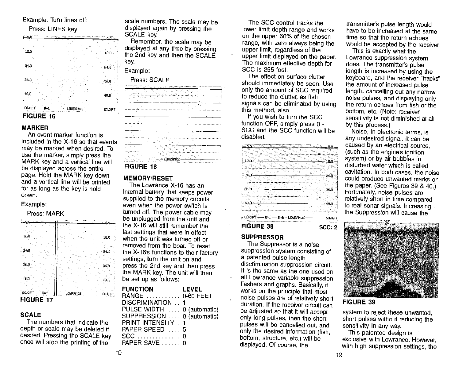
The SCC
control tracks the
lower limit depth range and works
on the upper
60% of the chosen
range, with zero always being the
upper
limit, regardless of the
upper limit displayed on the
paper
The maximum effective depth for
SCC is 255 feet.
The effect on surface clutter
should immediately be seen. Use
only the amount of SCC
required
to reduce the clutter, as fish
signals can be eliminated by using
this method, also.
If you
wish to turn the 5CC
function OFF, simply press 0 -
SCC and the SCC function will be
disabled.
12.0 - t2.0—
240 240—
36.0 26.0
49.0
60.0 FT
—
01
—
62
— LOl/RANCE 60.0 st
FIGURE 38 -
SCC: 2
SUPPRESSOR
The Suppressor is a noise
suppression system consisting of
a patented pulse
length
discrimination suppression circuit.
It is the same as the one used on
all Lowrance variable suppression
flashers and graphs. Basically, it
works on the
principle that most
noise
pulses are of relatively short
duration, If the receiver circuit can
be adjusted so that it
will accept
only long pulses, then the short
pulses will be cancelled out, and
only the
desired information (fish,
bottom, structure, etc.) will be
displayed. Of course, the
transmitter's pulse length would
have to be increased at the same
time
so that the return echoes
would be accepted by the receiver.
This is exactly what the
Lowrance suppression system
does. The
transmitter's pulse
length is increased by using the
keyboard, and the receiver 'tracks"
the amount of increased pulse
length, cancelling out any
narrow
noise
pulses, and displaying only
the return echoes from fish or the
bottom, etc. (Note: receiver
sensitivity is not diminished at all
by this process.)
Noise, in electronic terms, is
any
undesired signal. It can be
caused by an electrical source,
(such as the engine's ignition
system) or by air bubbles in
disturbed water which is called
cavitation. In both cases, the noise
could produce unwanted marks on
the paper. (See Figures 39 & 40.)
Fortunately,
noise pulses are
relatively short in time
compared
to real sonar signals. Increasing
the Suppression will cause the
system to reject these unwanted,
short pulses without
reducing the
sensitivity in any way.
This patented design is
exclusive with Lowrance. However,
with high suppression settings, the
Example: Turn lines off:
Press: LINES key
12.0
240
36.0
40.0
60.0FT
12.0
240 -
36.0
40.0
60.OFT 91
FIGURE 17
12.0
24.0
26.0
40.0
L0URAMCE LEVEL
0-60 FEET
0 (automatic)
0 (automatic)
0
0
FIGURE 39
to 19
PDF compression, OCR, web-optimization with CVISION's PdfCompressor
washed periodically with mild
soapy water to remove any
accu-
mulated road
grime or oily film.
This is essential to have good
contact between the transducer
and the water.
Periodically,
the rubber roller on
the paper
drive should be cleaned
with a cloth
dampened with alco-
hol to improve the friction on the
metering roller drive.
Don't open the case or the
transport assembly
when the unit
is running. The stylus holder and
stylus may
be damaged or per-
sonal injury may result.
TROUBLESHOOTING
ADVANCED OPERATION
Surface Clarity Control (SCC)
The surface markings at the top
of
the chart paper
can, at times,
extend many
feet below the
surface. This often interferes with
fish signals or other
targets. This
is called Surface Clutter and is
caused by algae and plankton, air
bubbles caused by wave action or
boat wakes, bait
fish, or
temperature inversions.
The surface clutter
markings
can be reduced or eliminated by
using the SOC control key on the
front
panel keyboard.
To use the 3CC, press key 1
thru 7 (depending upon the
amount of 3CC desired) and then
the SCC
key. 1 has a minimum
effect on surface clutter, 7 has the
maximum effect on reducing
surface clutter. 2 thru 6 have
intermediate effects. The amount
of SCC that is used is printed at
the bottom of the chart paper. If
one level of SCC is used, then
3CC-i is printed. Two levels,
SCC-2, etc.
POWER BOOSTER OFF
ALTERNATE TRANSMIT &
PRINT OFF
LINES ON
SCALES ON
FREQUENCY
CONVERTER OFF
BATTERY BACKUP ON
If you
do not recognize some of
the functions listed above, look in
the Advanced Operation section of
this manual for more instructions.
The
Memory function can be
turned on or off as desired. When
the Memory function is turned off,
only the depth mode (Feet,
Fathoms, or Meters) will be
retained.
To turn the Memory function off,
press ii -2nd-5.
To turn the Memory function on,
press 10- 2nd -5.
FEET, FATHOMS,
METERS
The X-i 6 will display the depth
in feet, fathoms, or meters.
Although the unit will revert back
to the feet mode whenever the
2nd - MARK feature is used
(see
above), it is simple to change to
any mode you wish by pressing
the 2nd key and then 1 for
feet,
2nd - 2 for fathoms, and 2nd - 3
for meters.
When the unit
is in the Feet
mode, the letters 'PT" will be
displayed next to the lower limit
depth scale. In the Fathom mode,
the letters "FA" will be displayed,
and the letter "M" will be
displayed when the unit is in the
meters mode.
6.0
0.0----—
to.0FA-— - 01
— L0tdHCE— — IO.DFA—
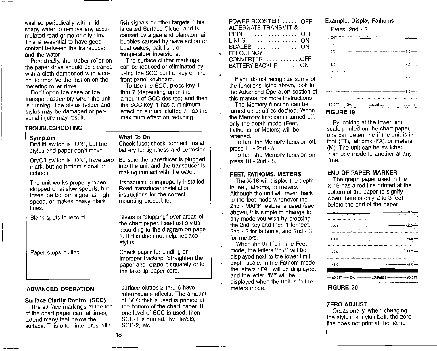
FIGURE 19
By looking at the lower limit
scale printed on the chart paper,
one can determine if the unit is in
feet (FT), fathoms (FA),
or meters
(M). The unit can be switched
from one mode to another at any
time.
END-OF-PAPER MARKER
The graph paper used in the
X-i 6 has a red line printed at the
bottom of the paper
to signify
when there is only 2 to 3 feet
before the end of the paper.
ZERO ADJUST
Occasionally, when changing
the stylus or stylus belt,
the zero
line does not print at the same
Example: Display Fathoms
Press: 2nd - 2
— 2.0---
Symptom
On/Off switch is "ON", but the
stylus and paper
don't move
On/Off switch is "ON", have zero
mark, but no bottom signal or
echoes.
The unit works properly when
stopped or at slow
speeds, but
loses the bottom signal at high
speed, or makes heavy
black
lines.
Blank spots
in record.
Paper stops pulling.
What
To Do
Check fuse; check connections at
battery for tightness and corrosion.
Be sure the transducer is plugged
into
the unit and the transducer is
making contact with the water.
Transducer is improperly installed.
Read transducer installation
instructions for the correct
mounting procedure.
Stylus is "skipping" over areas of
the chart paper. Readjust stylus
according to the diagram on page
?. If this does not help, replace
stylus.
Check paper for binding or
improper tracking. Straighten the
paper and retape it squarely onto
the take-up paper core.
—-.---—:h-n-=
h
iao
H- 24.0 24.0—i
36,0 36.0
46.0 40.0—
LF1E
FIGURE 20
18 ii
PDF compression, OCR, web-optimization with CVISION's PdfCompressor
place
near the top of the chart
paper. A zero adjust
control has
been placed on the back inside
wall of the X-1 6 near the
upper
left hand corner so that the zero
line position may be adjusted on
the paper.
Open the case front and look for
the decal marked "ZERO
ADJUST". You may
have to pull
the paper transport assembly
down to see the decal for the first
time. Push the transport closed
and turn on the unit. (CAUTION
— Keep hands away from the
stylus belt and stylus. High volt-
age is present.)
Insert a 6-8' long screwdriver
with a l/g" blade into the zero
adjust hole and rotate the control
until the zero line is at the desired
position. (Note: this may also be
adjusted with the unit
turned OFF.)
Adjust
the control, then remove
the screwdriver and turn power
back ON. Repeat until the zero
line is in the desired position.
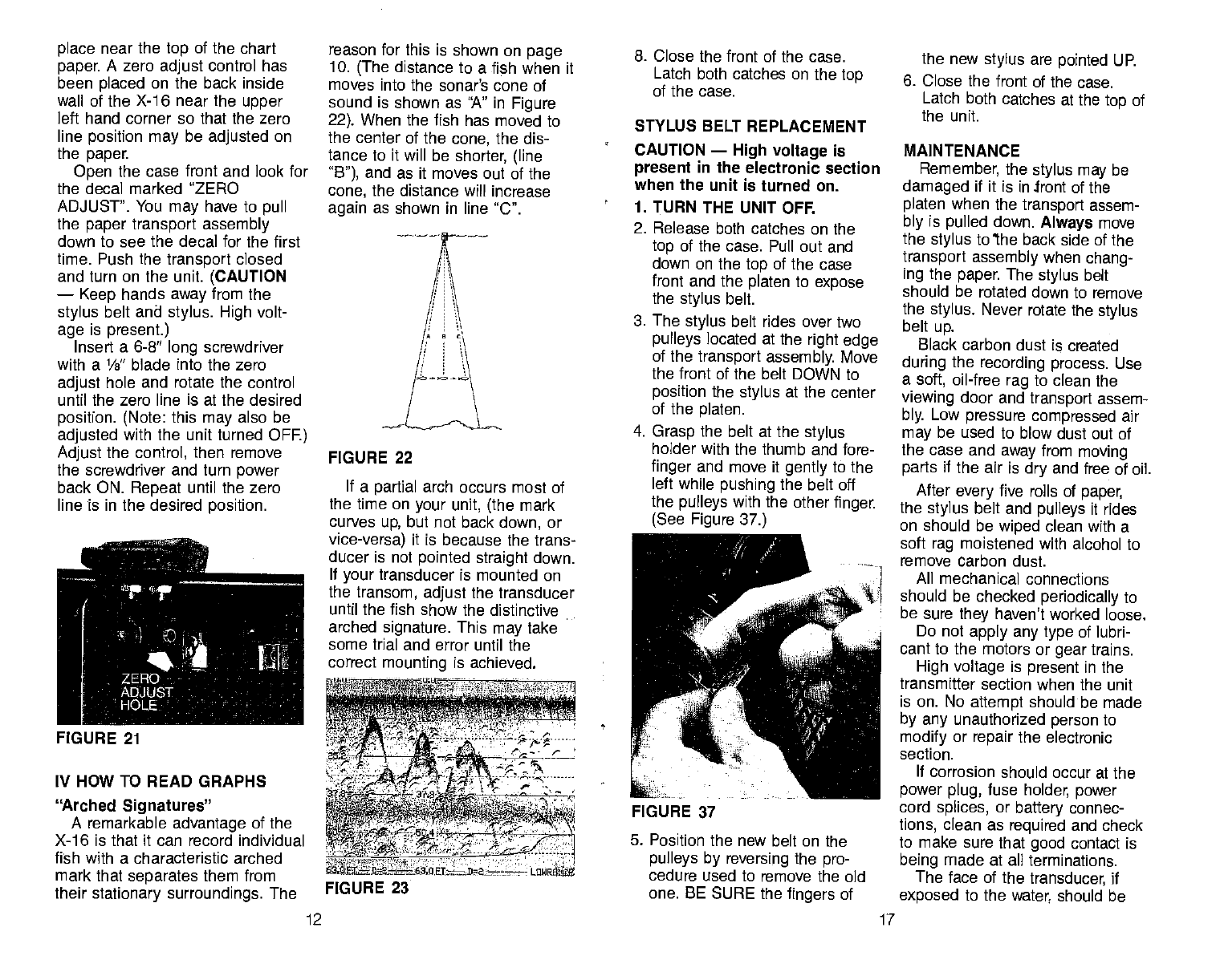
IV HOW TO READ GRAPHS
'rched
Signatures"
A remarkable advantage of the
X-16 is that it can record individual
fish with a characteristic arched
mark that separates them from
their stationary surroundings. The
reason for this is shown on page
10. (The distance to a fish when it
moves into the sonar's cone of
sound is shown as "A" in Figure
22). When the fish has moved to
the center of the cone, the dis-
tance to it will be shorter, (line
"B"), and as it moves out of the
cone, the distance will increase
again as shown in line "C".
8. Close
the front of the case.
Latch both catches on the top
of the case.
STYLUS BELT REPLACEMENT
CAUTION — High voltage is
present in the electronic section
when the unit is turned on.
1. TURN THE UNIT OFF.
2. Release both catches on the
top of the case. Pull out and
down on the top of the case
front and the platen to expose
the stylus belt.
3. The stylus belt rides over two
pulleys located at the right edge
of the transport assembly.
Move
the front of the belt DOWN to
position the stylus at the center
of the platen.
4. Grasp the belt at the stylus
holder with the thumb and fore-
finger and move it gently
to the
left while
pushing the belt off
the pulleys with the other finger.
(See Figure 37.)
5. Position the new belt on the
pulleys by reversing
the pro-
cedure used to remove the old
one. BE SURE the fingers of
the new stylus are pointed UP.
6. Close the front of the case.
Latch both catches at the top of
the unit.
MAINTENANCE
Remember,
the stylus may be
damaged if it is in front of the
platen when the transport assem-
bly is pulled down. Always move
the
stylus to'the back side of the
transport assembly when chang-
ing the paper. The
stylus belt
should be rotated down to remove
the stylus. Never rotate the stylus
belt
up.
Black carbon dust is created
during the recording process. Use
a soft, oil-free rag to clean the
viewing door and transport assem-
bly. Low pressure compressed air
may
be used to blow dust out of
the case and away from moving
parts if the air is dry and free of oil.
After
every
five rolls of paper,
the
stylus
belt and pulleys it rides
on should be wiped clean with a
soft rag moistened with alcohol to
remove carbon dust.
All mechanical connections
should be checked periodically
to
be sure they haven't worked loose.
Do not apply any type
of lubri-
cant to the motors or
gear
trains.
High voltage
is present in the
transmitter section when the unit
is on. No attempt should be made
by any
unauthorized person to
modify or repair
the electronic
section.
If
corrosion should occur at the
power plug, fuse holder, power
cord splices, or battery connec-
tions, clean as required and check
to make sure that good contact is
being made at all terminations.
The face of the transducer,
if
exposed to the water, should be
FIGURE 22
If a partial arch occurs most of
the time
on your unit, (the
mark
curves up, but not back down, or
vice-versa) it is because the trans-
ducer is not pointed straight down.
If your
transducer is mounted on
the transom, adjust
the transducer
until the fish show the distinctive
arched signature. This
may
take
some trial and error until the
correct mounting is achieved.
FIGURE 21 a :4rwt:rr:
-' ,-,t - -7' _i'"- -.
- ____
,— fl.8 r——r
U E1-—
D2rt-z----- LUWRSS
FIGURE 23
FIGURE 37
12 17
PDF compression, OCR, web-optimization with CVISION's PdfCompressor
10. Push the transport assembly
back to its operating position.
Be sure it engages the catch
inside the case.
11. Close the front of the case.
Latch both catches on the
top.
12. Turn the unit on. Move the
Chart Speed knob fully clock-
wise. Watch the paper long
enough to be sure it is moving
smoothly and evenly across
the platen. If the paper
flutters
or begins to run "uphill",
repeat step
6.
STYLUS REPLACEMENT
CAUTION
— High voltage is
• present in the electronic section
when the unit is turned on.
1. TURN THE UNIT OFF.
2. Release both catches on the
top of the case. Pull out and
• down on the top of the case
front to expose the stylus
belt.
(See Figure 24).
3. The
stylus
belt
rides over two
pulleys located at the right edge
of the transport assembly. Move
the front of the belt DOWN to
position the stylus
at the center
of the platen.
4. Hold the stylus belt
stationary
with one finger, and remove the
old stylus by starting at its left
edge and moving it out from
under the tabs on the stylus
holder.
FIGURE 35
be sure it is bent properly by
comparing it to Figure 34.
6. Refer to Figure 35 to be sure
the new stylus
is positioned
correctly under the tabs on the
holder. Be sure it moves freely
in the two slots. If not, bend the
stylus away from the edge it is
rubbing on until it does move freeIt
N2.o 12.0
f ,[ .ai'o.m 41
I
7. After installing, if the stylus
won't print all the way down the
paper as shown in Figure 36,
bend the right leg
down so that
more pressure is exerted
against the stainless steel plate.
If it still does not print all the
way, bend the left leg down
more, but not so far that it digs
into the paper.
Sharp, well defined signatures
will occur most often when the
Sensitivity knob is set at the ¾
point, or higher. Remember,
that
there must be some movement
between the boat and the fish to
develop the arched mark, Usually
this means trolling at very
slow
speeds with the main engine in
gear at minimum throttle setting.
THERMOCLINES
The temperature
of water in the
lake is seldom constant from
top
to bottom. Layers of different tem-
peratures form, and the
junction
of
a warm and cool layer of water is
called a thermocline. (See Figure
23) The depth and thickness of
the thermocline can vary
with the
season or time of day. In deep
lakes there
may
be two or more,
at different depths. Thermoclines
are important to the fisherman
because they are areas where fish
are active. Many times bait fish
will te above the thermocline
while larger game fish suspend
just below it.
Your Lowrance X-16 can detect
this invisible layer in the water, but
the Sensitivity knob will probably
have to be set at the 1/2 point, or
higher.
PAPER LOADING
NOTE: There are many imitators
manufacturing chart paper that is
inferior to ours. Use only
Lowrance LPG-605 or LPG-606
chart paper
in your
X-16.
NOTE —
A stylus is enclosed with
every package of LPG—606 chart
paper. For best results, install the
new stylusevery other time a roll of
chart paper is changed.
CAUTION — High voltage is
present in the electronic section
when the unit is
turned on.
1. TURN THE UNIT OFF.
2. Release both catches on the
top of the case. Pull out and
down on the top of the case
front
to expose the platen
assembly. (See Figure 24).
3. Move the stylus bolt DOWN, to
position the marking stylus on
the back side of the platen.
NEVER move the belt up — it
could damage the stylus. (See
Figure 25).
13
FIGURE 24
5. Before installing the new stylus,
FIGURE 36
FIGURE 34
16
FIGURE 25
PDF compression, OCR, web-optimization with CVISION's PdfCompressor
Special Note: The
stylus may
be damaged if the transport
assembly is pulled down
unless the stylus has been
moved to the back side of the
platen.
4. Pull out and down on the tab
at the top center
of the
platen
assembly to expose the
paper
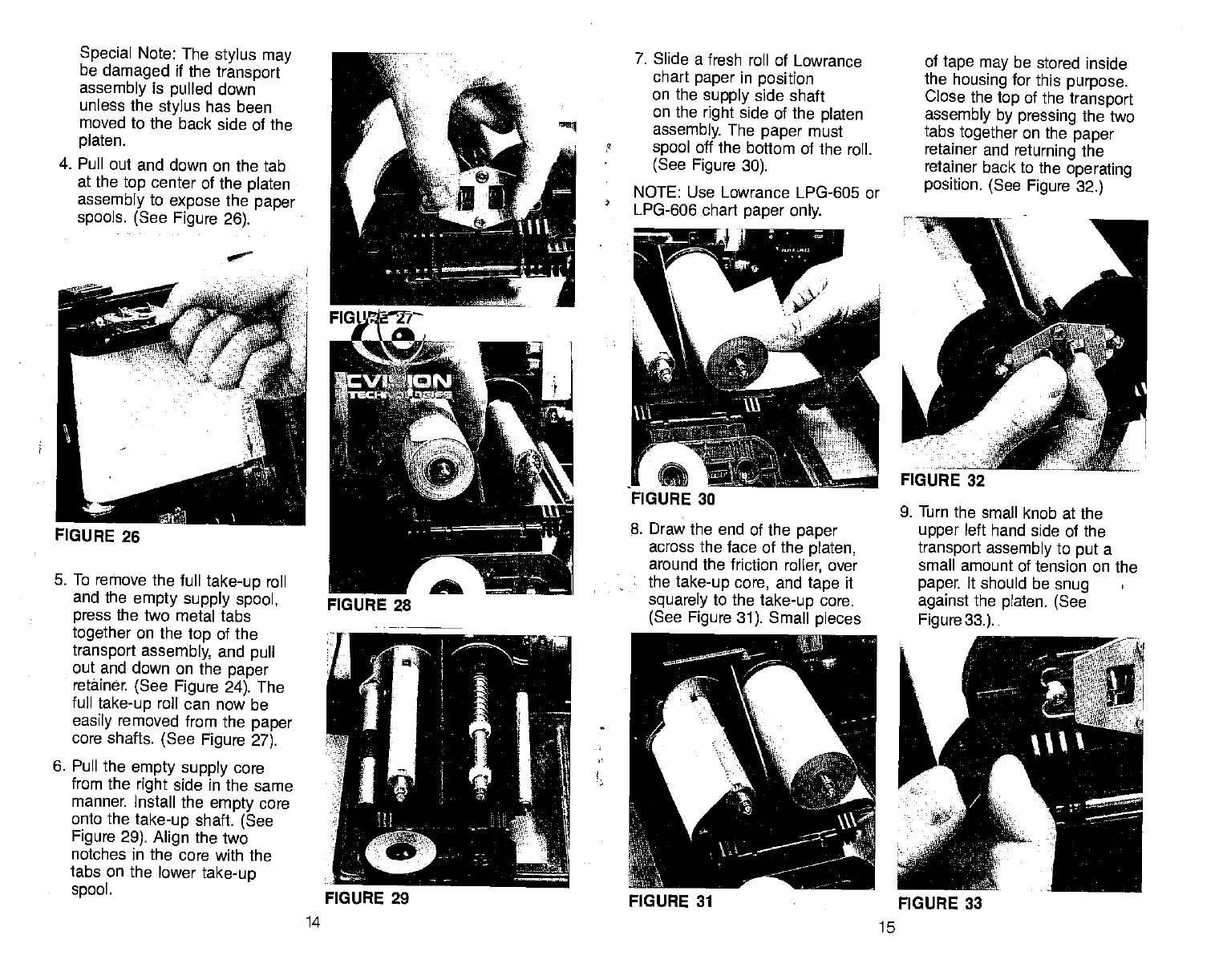
spools. (See Figure 26).
5. To remove the full take-up
roll
and the empty supply spool,
press the two metal tabs
together on the top of the
transport
assembly, and pull
out and down on the paper
retainer. (See Figure 24). The
full take-up
roll can now be
easily removed from the
paper
core shafts. (See Figure 27).
6. Pull the empty supply
core
from the right side in the same
manner Install the
empty
core
onto the take-up shaft. (See
Figure 29). Align the two
notches in the core with the
tabs on the lower
take-up
spool.
7. Slide a fresh roll of Lowrance
chart paper
in position
on the supply side shaft
on the right side of the
platen
assembly. The paper
must
spool off the bottom of the roll.
(See Figure 30).
NOTE: Use Lowrance LPG-605 or
LPG-606 chart paper only.
8. Draw the end of the paper
across the face of the platen,
around the friction roller, over
the take-up core, and tape it
squarely to the take-up
core.
(See Figure 31). Small pieces
14 15
of
tape may be stored inside
the housing for this purpose.
Close the top of the transport
assembly by pressing the two
tabs together on the paper
retainer and returning the
retainer back to the operating
position. (See Figure 32.)
•0
FIGURE 26
9. Turn the small knob at the
upper left hand side of the
transport assembly to put a
small amount of tension on the
paper. It should be snug
against the platen. (See
Figure
33.).
FIGURE 29 FIGURE 31 FIGURE 33
PDF compression, OCR, web-optimization with CVISION's PdfCompressor
