Lowrance Electronic X 70A 3D Users Manual Owners
X-70A 3D to the manual 60198e55-ba78-4321-a9f2-a82c0fbe7f8a
2015-02-05
: Lowrance-Electronic Lowrance-Electronic-X-70A-3D-Users-Manual-407694 lowrance-electronic-x-70a-3d-users-manual-407694 lowrance-electronic pdf
Open the PDF directly: View PDF ![]() .
.
Page Count: 44

X-70A 3DX-70A 3D
X-70A 3DX-70A 3D
X-70A 3D
INSTINST
INSTINST
INSTALLAALLA
ALLAALLA
ALLA
TION AND OPERATION AND OPERA
TION AND OPERATION AND OPERA
TION AND OPERATIONTION
TIONTION
TION
INSTRINSTR
INSTRINSTR
INSTRUCTIONSUCTIONS
UCTIONSUCTIONS
UCTIONS
LOWRANCE
ELECTRONICS, INC.
®

TABLE OF CONTENTSTABLE OF CONTENTS
TABLE OF CONTENTSTABLE OF CONTENTS
TABLE OF CONTENTS
INTRODUCTION .............................................................................................................................. 1
SPECIFICATIONS ...........................................................................................................................1
INSTALLATION ...............................................................................................................................1
TRANSDUCER ............................................................................................................................ 1
SONAR UNIT............................................................................................................................... 5
POWER CONNECTIONS ............................................................................................................ 6
KEYBOARD BASICS .................................................................................................................. 7
DISPLAY .......................................................................................................................................... 8
MODES OF OPERATION ................................................................................................................ 9
OPERATION ...................................................................................................................................11
AUTOMATIC ...............................................................................................................................11
SENSITIVITY .............................................................................................................................. 11
3D OPERATION .............................................................................................................................12
3D RANGE .................................................................................................................................12
3D ZOOM ................................................................................................................................... 12
3D VARIVIEW™ .........................................................................................................................13
2D OPERATION .............................................................................................................................15
2D TRANSDUCER ELEMENT SELECTION ..............................................................................15
2D RANGE .................................................................................................................................15
2D RANGE - Upper and Lower Limits ........................................................................................16
2D ZOOM - Automatic Operation ................................................................................................17
2D ZOOM - Manual Operation .................................................................................................... 18
BOTTOM DEPTH VIEW ................................................................................................................. 18
FASTRAK™ ...................................................................................................................................19
MENU - PAGE 1 ............................................................................................................................. 20
STOP CHART ............................................................................................................................. 20
ALARMS ..................................................................................................................................... 20
DEPTH ALARMS .....................................................................................................................21
ZONE ALARM .........................................................................................................................22
FISH ALARM ...........................................................................................................................23
MUTE ALARM ......................................................................................................................... 23
FISH I.D. .....................................................................................................................................23
DISPLAY CONTRAST ................................................................................................................24
2D VIEW OPTIONS .................................................................................................................... 25
DIGITAL BOX OPTIONS ......................................................................................................... 25
DIGITAL SONAR ..................................................................................................................... 26
2D FASTRAK™ BAR ..............................................................................................................26
ZOOM BAR.............................................................................................................................. 27
ZONE ALARM BAR .................................................................................................................27
CHART CURSOR ....................................................................................................................27
MENU - PAGE 2 ............................................................................................................................. 28
GRAYLINE® ............................................................................................................................... 28
CHART SPEED ..........................................................................................................................29
ADJUST BACK LIGHT LEVEL ...................................................................................................29
SPEAKER VOLUME ..................................................................................................................30
UNITS OF MEASURE ................................................................................................................30
MENU - PAGE 3 ............................................................................................................................. 31
SURFACE CLARITY CONTROL ................................................................................................31
ASP (Advanced Signal Processing)............................................................................................ 31
FISHTRACK™ ............................................................................................................................32
ADJUST TEMPERATURE GRAPH ............................................................................................ 32
RESET DISTANCE LOG ............................................................................................................33
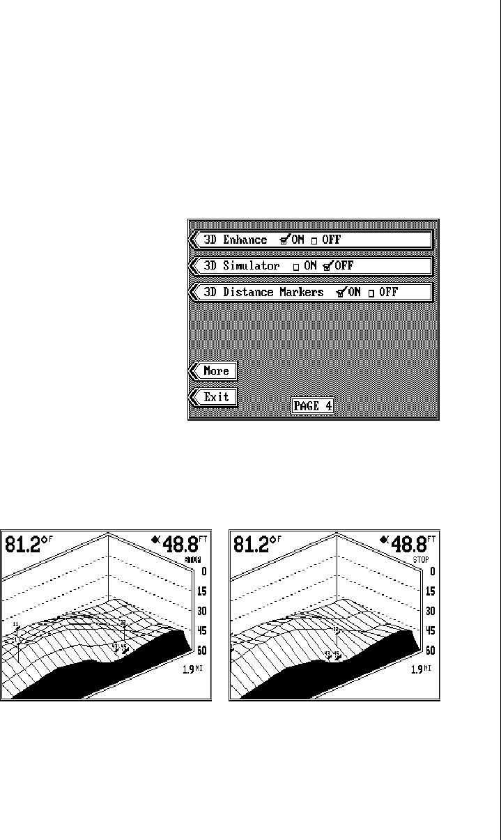
MENU - PAGE 4 ............................................................................................................................. 33
3D ENHANCE ............................................................................................................................ 33
3D SIMULATOR .........................................................................................................................34
3D DISTANCE MARKERS .........................................................................................................34
TROUBLESHOOTING ....................................................................................................................35
NOISE ........................................................................................................................................ 35
MISSING PARTS ............................................................................................................................38
LOWRANCE FULL ONE YEAR WARRANTY ................................................................................39
UPS RETURN SERVICE ................................................................................................................40
ACCESSORY ORDERING INFORMATION ...................................................................................41
Copyright © 1994, Lowrance Electronics, Inc. All rights reserved.
All features and specifications subject to change without notice.
All screens in this manual are simulated.

1
INTRODUCTION
Thank you for purchasing an X-70A 3D. Its adjustable VariView™ 3D per-
spective lets you rotate the underwater picture to accommodate specific
viewing needs. In addition to the 3D views, the X-70A 3D also gives you
outstanding 2D detail using either the supplied 384 kHz transducer or an
optional 192 kHz transducer.
SPECIFICATIONS
Dimensions..................................... 5 7/8" H x 7 3/4"W x 3 7/8"D
Transmitter Frequency ....................384 kHz and 192 kHz
Transmitter Power ........................... 3000 watts (peak-to-peak, typical)
375 watts (RMS, typical)
Display............................................Supertwist LCD
200 vertical x 320 horizontal
64,000 total pixels
NOTICE!
The storage temperature for your unit is from -4 degrees to +167 degrees
Fahrenheit (-20 degrees to +75 degrees Celsius). Extended storage in
temperatures higher or lower than specified will damage the liquid crystal
display. This type of damage is not covered by the warranty.
INSTALLATION
TOOLS AND HARDWARE YOU WILL NEED
Screwdriver
Four #10 screws with flat washers or up to 1/4" screws (to attach gimbal
bracket to dash)
Hand-held drill with a 5/32" drill bit
Marine grade caulking compound
TRANSDUCER INSTALLATION:
The HS-3D4 supplied with your X-70A 3D is a 384 kHz, 4 element, high-
speed, transom mount transducer. It can be installed on any outboard or
stern-drive (inboard-outboard) powered boat. The built-in “kick-up” bracket
helps prevent damage if the transducer strikes an object while the boat is
moving. If the transducer does “kick-up”, it can be pushed back in place
without tools.
Read this section carefully before attempting the installation. Determine
the best mounting location for your boat. Remember, the transducer loca-
tion is the most critical part of a sonar installation. If it isn’t done properly,
the sonar can’t perform to it’s designed potential.
2
Transducer Location
1. The transducer must be placed in a location that has a smooth flow of
water at all times. If the transducer is not placed in a smooth flow of
water, interference will show on the sonar’s display in the form of ran-
dom lines or dots whenever the boat is moving and can completely
mask the sonar image at high speed.
2. The transducer should be installed with its face pointing straight down,
if possible.
3. Make certain the chosen location doesn’t interfere with the boat’s trailer.
Also, don’t mount it closer than about one foot from the engine’s lower
unit. This will prevent cavitation interference with the propeller. Typi-
cally, the transducer should be mounted as far down on the transom
as possible. This increases the chance that it will remain in the water
at high speed or sharp turns, and reduces the possibility of air bubble
interference (cavitation).
4. Don’t mount the transducer directly behind strakes or ribs on the bot-
tom of the hull. Typically, a good location on aluminum boats is be-
tween the ribs closest to the engine. The port (left) side of the transom
is preferred for mounting the transducer, however, if this is not pos-
sible, the starboard (right) side can be used, usually with good results.
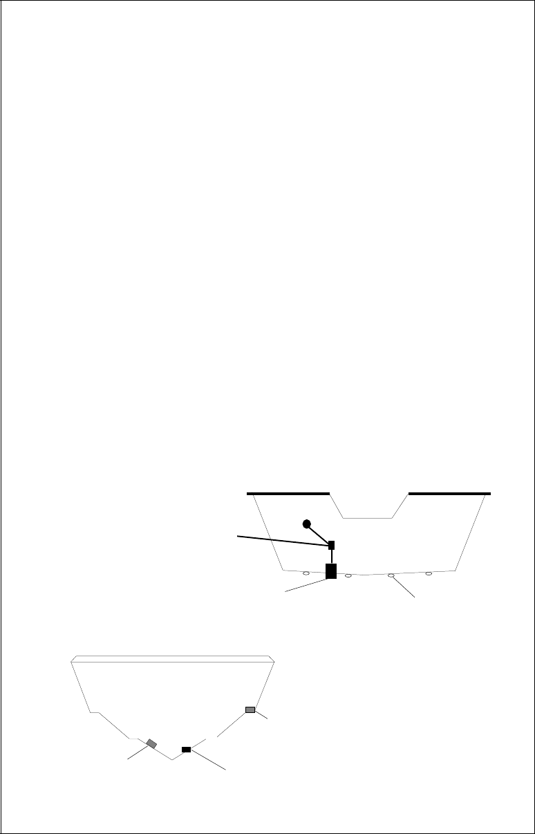
POOR ANGLEPOOR ANGLE
POOR ANGLEPOOR ANGLE
POOR ANGLE
POOR LOCATIONPOOR LOCATION
POOR LOCATIONPOOR LOCATION
POOR LOCATION
GOOD LOCATIONGOOD LOCATION
GOOD LOCATIONGOOD LOCATION
GOOD LOCATION
CAUTION!
CLAMP THE TRANSDUCER CABLE TO
TRANSOM NEAR THE TRANSDUCER. THIS
WILL HELP PREVENT THE TRANSDUCER
FROM ENTERING THE BOAT IF IT IS
KNOCKED OFF AT HIGH SPEED.
GOOD LOCATIONGOOD LOCATION
GOOD LOCATIONGOOD LOCATION
GOOD LOCATION RIBS ON
ALUMINUM
BOATS
3
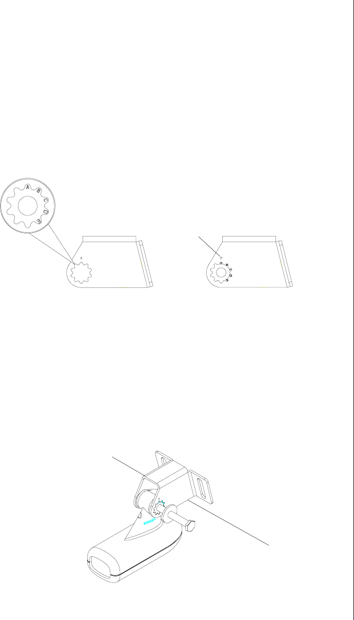
Transducer Assembly and Mounting
The best way to install this transducer is to loosely assemble all of the
parts first, place the transducer’s bracket against the transom and see if
you can move the transducer so that it’s parallel with the ground.
1. Press the two small plastic ratchets into the sides of the metal bracket
as shown below. Notice there are letters molded into each ratchet.
Place each ratchet into the bracket with the letter “A” aligned with the
dot stamped into the metal bracket. This position sets the transducer’s
coarse angle adjustment for a fourteen (14) degree transom. Most
outboard and stern-drive transoms have a fourteen degree angle.
2. Slide the transducer between the two ratchets. Temporally slide the
bolt though the transducer assembly and hold it against the transom.
Looking at the transducer from the side, check to see if it will adjust so
that its face is parallel to the ground. If it does, then the “A” position is
correct for your hull. If the transducer’s face isn’t parallel with the ground,
remove the transducer and ratchets from the bracket. Place the ratch-
ets into the holes in the bracket with the letter “B” aligned with the dot
stamped in the bracket. Reassemble the transducer and bracket and
place them against the transom. Again, check to see if you can move
the transducer so it’s parallel with the ground. If it does, then go to step
3. If it doesn’t, repeat step 2, but use a different letter until you can
place the transducer on the transom correctly.
DOT
4
3. Once you determine the
correct position for the
ratchets, assemble the
transducer as shown at
left. Do not tighten the lock
nut at this time.
NUT
METAL
WASHER
RUBBER
WASHERS METAL
WASHER
BOLT
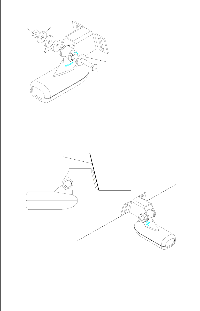
4. Hold the transducer and bracket assembly against the transom. The
transducer should be roughly parallel to the ground. The bottom of the
transducer bracket should be in line with the bottom of the hull.
Don't
let the bracket extend below the hull!
Mark the center of the slots for
the mounting holes. Drill two 5/32" holes in the marked locations for
the #10 screws supplied with the transducer.
5. Attach the transducer to the transom. Slide the transducer up or down
until it’s aligned properly on the transom as shown above. Tighten the
bracket’s mounting screws. Adjust the transducer so that it’s parallel to
the ground and tighten the lock nut until it touches the flat washer, then
add 1/4 turn.
Don’t over tighten the lock nut!
If you do, the transducer
won’t “kick-up” if it strikes an object in the water.
TRANSOM
SIDE VIEW

5
6. Route the transducer cable to the sonar unit. If possible, route the
transducer cable away from other wiring on the boat. Electrical noise
from the engine’s wiring, bilge pumps, VHF radio wires and cables,
and aerators can be picked up by the sonar. Use caution when routing
the transducer cable around these wires.
IMPORTANT!
Clamp the transducer cable to the transom close to the transducer. This
can prevent the transducer from entering the boat if it is knocked off at
high speed.
7. Make a test run to determine the results. If the bottom is lost at high
speed, or if noise appears on the display, try sliding the transducer
bracket down. This puts the transducer deeper into the water, hope-
fully below the turbulence causing the noise. Do not allow the trans-
ducer bracket to go below the bottom of the hull!
SONAR UNIT MOUNTING
Install the X-70A 3D in any convenient location, provided there is clear-
ance behind the unit when it is tilted for the best viewing angle. Holes in
the bracket base allow wood screw or through-bolt mounting. Make cer-
tain there is enough room behind the unit to attach the power and trans-
ducer cables.
Using the bracket as a template, mark the dash for the mounting holes,
then make a mark in the center of the bracket location for the cable hole.
If you want the smallest possible hole for the power and transducer cables
in the dash, install the transducer first, then route the cable to the desired
location. The smallest hole that will pass one power or transducer plug is
5/8". After the hole is drilled, pass the transducer connector up through
the hole first, then pass the power cable down through it.
After routing the cables, fill the hole with a good marine sealing com-
pound. Place the bracket over the hole and route the cables through the
slot in the back of the bracket. Break out one of the other slots for the
transducer cable. Screw the bracket to the dash.
FRONT
SLOT BREAK OUT SLOT
6
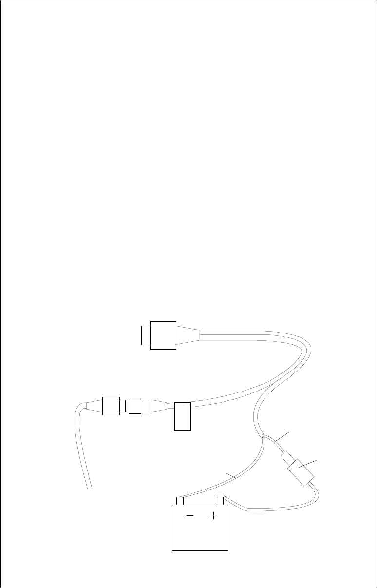
POWER CONNECTIONS
The X-70A 3D works from a twelve-volt battery system. For the best re-
sults, attach the power cable directly to the battery. You can attach the
power cable to an accessory or power buss, however you may have prob-
lems with electrical interference. Therefore, it’s safer to go ahead and
attach the power cable directly to the battery. If the cable isn’t long enough
to reach the battery, splice #18 gauge wire onto it. The power cable has
two wires, which are red and black. Red is the positive lead, black is nega-
tive or ground. Make certain to attach the in-line fuse holder to the red
lead as close to the power source as possible. For example, if you have to
extend the power cable to the battery or power buss, attach one end of
the fuse holder directly to the battery or power buss. This will protect both
the unit and the power cable in the event a short occurs.
IMPORTANT!
Do not use this product without a 3-amp fuse wired into the power cable!
Failure to use a 3-amp fuse will void your warranty.
If you’ve purchased the optional ST-T speed/temperature sensor, install it
according to the instructions included with the sensor. Route its cable to
the X-70A 3D’s power cable and plug it into the connector marked “SPEED/
TEMP CABLE”.
12 VOLT
BATTERY
TO
SPEED/
TEMP
SENSOR
RED
WIRE
3 amp
FUSE
BLACK
WIRE
TO X-70A 3D'S
POWER CONNECTOR
SPEED/
TEMP
CABLE
7
KEYBOARD
The keyboard is arranged for convenient operation. A ten-key keypad on
the right side of the screen lets you enter numbers. Arrow keys beneath
the keypad are used to adjust features. The keys in the left column are
used to select menu features. The keys along the bottom of the screen let
you select the basic sonar functions.
SENS Press this key to adjust the unit’s sensitivity.
RANGE This key lets you adjust the range shown on the display.
ZOOM This switches the chart between two times and four times zoom.
AUTO This turns the automatic feature off or on.
WINDOWS This key lets you select the different display modes.
MENU Press this key to show the menus.
ARROW KEYS These keys are used to make adjustments on menus.
ON The “On” key turns the unit on and also turns the backlights on.
OFF Press and HOLD the Off key to turn the X-70A 3D off.
FULL CHART This key switches the digital box between small and
large digits when the 2D chart is displayed.
123
789
456
LOWRANCE
0
CLR ENT
WINDOWS MENU
OFF ON
SENS RANGE ZOOM AUTO
X70A 3D
FULL CHART
8
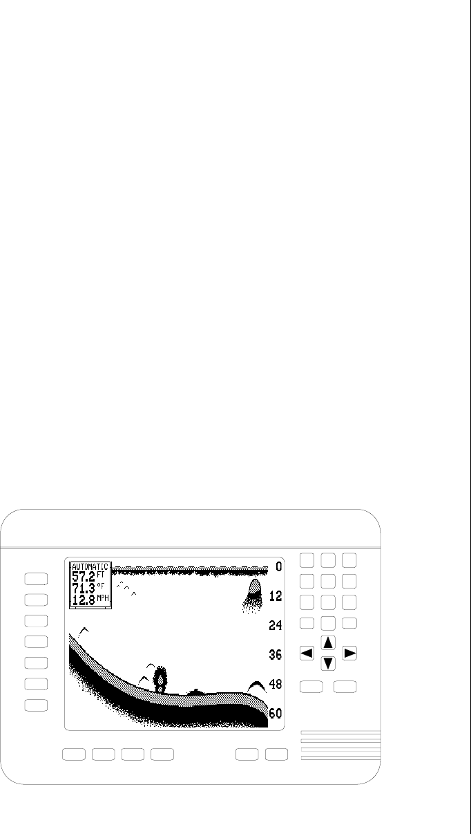
DISPLAY - General
When the X-70A 3D is first turned on, the display looks similar to the one
below. The 3D screen scrolls from right to left, with the scale on the right
side of the screen. The current depth beneath the transducer shows in
the upper right corner of the display. A fish symbol to the left of the depth
shows that the Fish ID feature is on. The word “AUTO” signifies that the
automatic function is on, keeping the bottom on the display at all times. If
the computer identifies targets as fish, one of four fish symbols appear on
the screen, depending on the size of the target. Numbers above the fish
symbol tell you the depth of the target. This feature is called “FishTrack”.
The lights are on for a few seconds when the X-70A 3D is turned on.
Menus appear at the same time. To leave the lights on, press the ON key.
This key controls the back lights. If you don’t want the lights on, wait a few
seconds and they will automatically turn themselves off. The menus will
also disappear after a few seconds, or you can press the CLEAR key to
erase them.
The Metric and Display menu labels work the same way. Press the key
adjacent to the Metric label to change the depth from feet to meters. This
also changes the temperature display to degrees Celsius, speed to knots,
and log to kilometers.
The Display menu on the screen's right side lets you adjust the display’s
for the best contrast. Press the left arrow key to decrease the contrast,
right arrow key to increase it.
The X-70A 3D automatically detects the speed/temperature sensor. If the
sensor is attached to the unit, speed, temperature, and distance log auto-
matically appear on the display. Distance markers also appear on the
9
screen, showing the distance behind the boat. If the speed/temperature
sensor is not plugged into the X-70A 3D, then none of these will show.
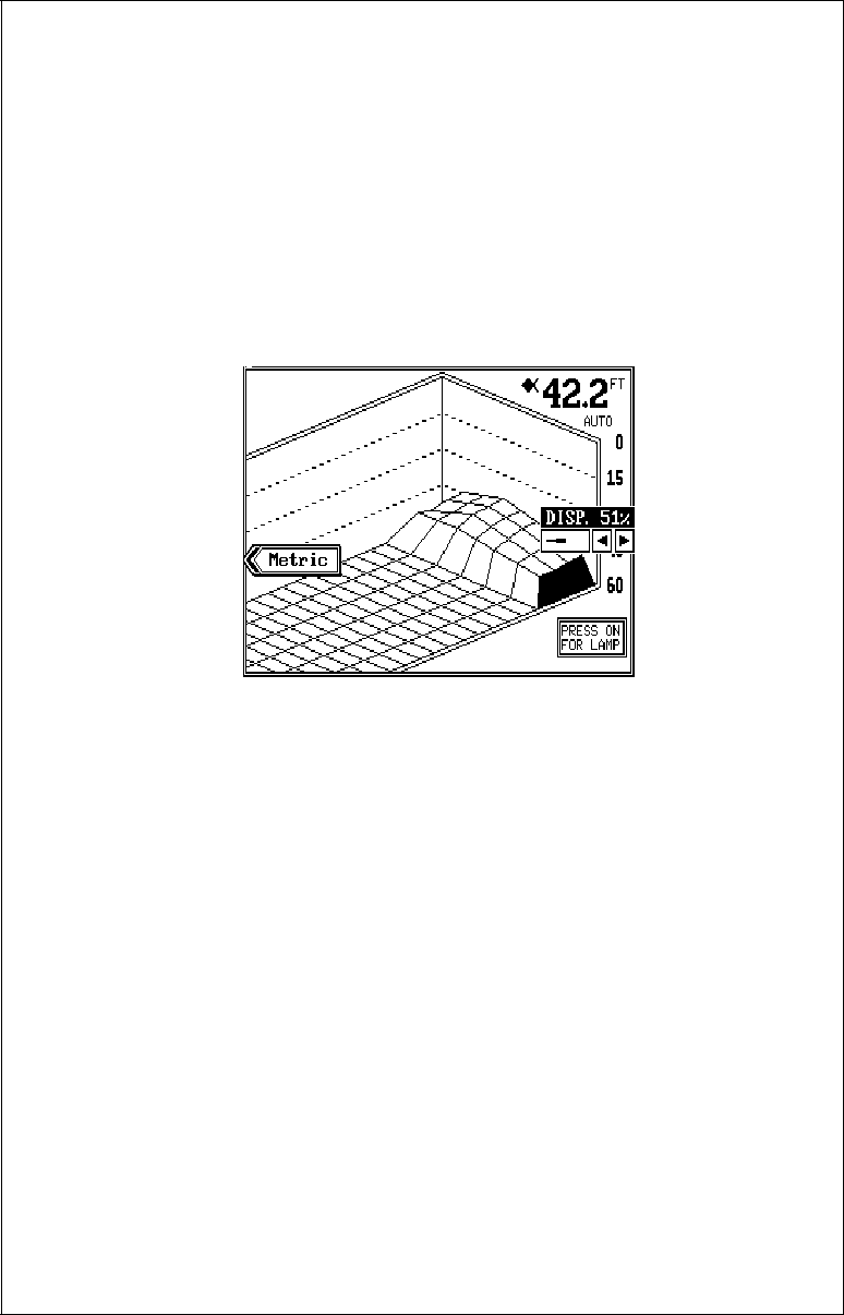
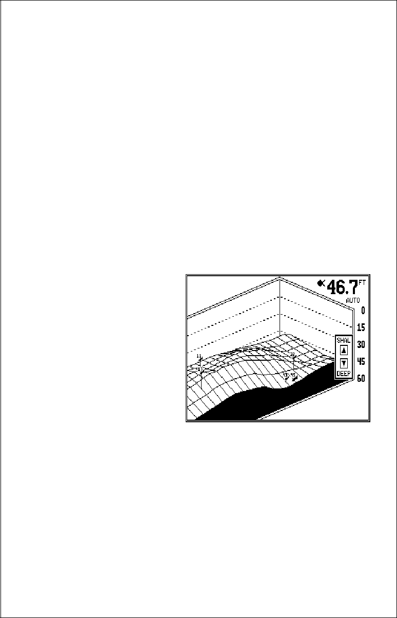
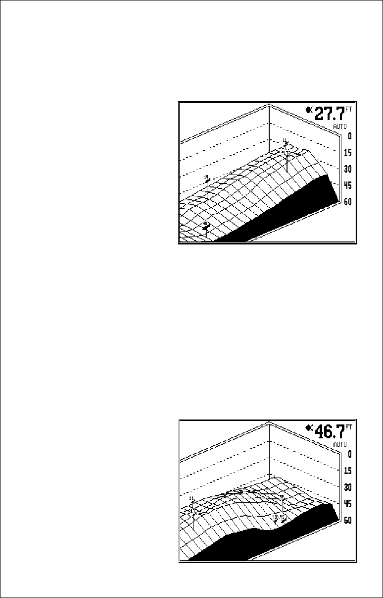
MODES OF OPERATION
The X-70A 3D shows a sonar picture of the underwater world in 3D, 2D,
Bottom Depth View, and FasTrack™ modes. The 2D and Bottom Depth
Views can use either the 384
or 192 kHz transducer (if the
optional 192 kHz transducer is
attached). The 3D mode is al-
ways 384 kHz. To switch be-
tween the different modes, first
press the WINDOWS key.
Press a key on the left side of
the screen to choose the de-
sired mode. Press the CLR
key to exit this menu.
In the 3D mode shown at right,
the bottom is represented by a “wire-frame” model. Only the bottom and
fish symbols show in this mode. Structure, weeds, thermoclines, etc. will
not show.
The X-70A 3D uses a 384 kHz transducer with four elements. The digital
depth display shows the bottom depth from the middle transducer ele-
ments. If it loses the signal from any element, a box with the word “LOST”
appears over the corresponding area on the display. This means the unit
cannot receive an echo from that element. This could be due to a large
drop-off, noise or other natural phenomenon.
The 2D mode looks like a conventional sonar display as shown below.
The bottom echo scrolls from right to left. The range displays on the right
side of the screen. The digital
bottom depth shows in the
upper left corner. When the X-
70A 3D is put into the 2D 384
kHz mode, the two center
transducer elements are in
use. The two outer elements
are turned off. You can select
the elements from a menu dis-
cussed in a later section. The
2D 192 kHz transducer has
only one element.
10
All 2D modes show the bottom signal, structure, thermoclines, fish (both
with and without the Fish ID feature), baitfish schools, and more. The 3D
view shows a 3D representation of the bottom, with Fish ID symbols only.
The 2D mode shows more information, the 3D mode makes it easier to
visualize the bottom contour.
The Bottom Depth View as
shown at right displays the
depth at the top of the display
in large digits. The graph
scrolls at high speed. Note that
this graph only shows the bot-
tom signal. No structure, fish
signals, or other echoes show
on this display. This feature is
available using either fre-
quency transducer. (384 Bot-
tom or 192 Bottom)
The 3D FasTrak screen con-
verts echoes from all four
transducer elements into short
horizontal lines. Typically, the
thicker the bar, the stronger
the echo. This screen is up-
dated rapidly, giving you
flasher-like performance. You
can view echoes from any or
all elements on this screen.
DIGITAL BOX
A box containing the digital
displays appears in the upper
left corner of the display when
a 2D display is enabled. You
can switch the size of the dis-
play from normal to large by
pressing the FULL CHART
key or by pressing the up or
down arrow keys on the selec-
tion menu.

11
OPERATION
The Automatic and Sensitivity features used on the X-70A 3D are the
same for all modes of operation. This section will explain these features.
For information on features specific to different modes, see the 2D or 3D
operation sections.
AUTOMATIC
The X-70A 3D adjusts the sen-
sitivity and range to keep a
detailed bottom signal on the
display when the automatic
feature is on. This is enabled
when the unit is first turned on.
You can turn this feature off to
gain greater control over the
adjustments and features of
this unit.
To turn automatic off, press the AUTO key. A screen similar to the one
above appears. Now press the AUTO key again. This moves the check
mark from the “AUTO” box to “MAN”. Press the CLR (clear) key to erase
the menu. To switch back to manual, repeat the above steps, but move the
check mark to the “AUTO” box using the AUTO key.
SENSITIVITY
The sensitivity control adjusts
the receiver’s ability to show
echoes. If it’s adjusted prop-
erly, the sonar unit shows not
only the bottom, but targets
(such as fish) with little or no
noise. If the sensitivity is
turned too low, no fish signals
will show, and you will lose the
bottom signal in fairly shallow
water.
When the X-70A 3D is in the automatic mode, the computer inside ad-
justs the sensitivity for the best setting. You can override this setting, add-
ing or subtracting the amount of sensitivity the computer uses. You can
also take complete control of the sensitivity level when the unit is in the
manual mode.
12
To adjust the sensitivity, press the SENS key. A menu appears on the
right side of the screen as shown on the previous page. Press the right
arrow key to increase it, the left arrow key to decrease it. When you have
it changed to the desired level, press the CLR key to erase the menu or
wait a few seconds for it to automatically clear.
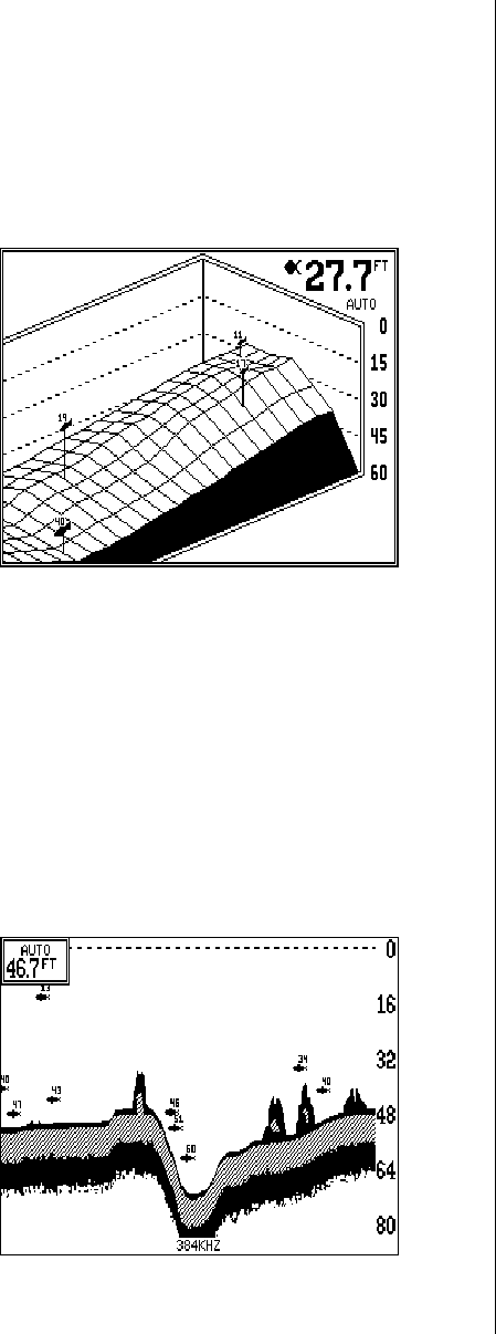
3D OPERATION
When the X-70A 3D is in the 3D mode, the Fish ID feature is always on
(unless you turn it off). FishTrack (the depth numbers above the fish sym-
bols) shows you the depth of the fish symbol and can be turned off, if
desired. See the FishTrack section in this manual for more information.
3D RANGE
The range is set by the unit as long as it’s in the auto mode. However, you
can adjust the range slightly when automatic is on. The unit won’t let you
move the bottom off the screen, and it will correct the range once the
bottom begins to go off the screen. When the unit is in the manual mode,
you can set the range to any that’s available.
To change the range on the X-
70A 3D, first press the RANGE
key. A screen similar to the one
at right appears. Simply press
the down arrow key to in-
crease the range or the up ar-
row key to decrease it. When
the desired range is chosen,
wait a few seconds and the
menu will automatically disap-
pear from the screen or press
the CLR key to erase it.
The X-70A 3D uses the following ranges: 0 - 5, 10, 20, 40, 60, 80, 100,
150, 200, 300, 400, 500, 700, and 900 feet.
3D ZOOM
The zoom feature enlarges all echoes on the screen, making them easier
to see. This feature works in automatic or the manual mode. (Note: If the
unit is in the 3D automatic mode and the zoom feature is turned on, the
unit will not change the range to a shallower setting. If the bottom signal
goes shallower than the zoom range, the X-70A 3D will simply show a flat
bottom signal at the shallowest range shown on the display. For example,
if you have a zoom range from 45 to 60 feet, and the bottom rises to 30
13
feet (shown by the digital depth
display), the unit will show a
flat bottom at 45 feet.)
To use the zoom feature, first
press the ZOOM key, then
press the key next to the zoom
menu that appears in the lower
left corner of the display as
shown at right. This switches
the unit to the 2X zoom mode.
This enlarges all echoes on
the screen to twice their nor-
mal size. If you press the key again while the menu is showing, the unit
will switch to the 4X zoom mode. This enlarges all echoes four times their
normal size.
Turn the zoom feature off by repeatedly pressing the key next to the zoom
menu until the check mark is on the OFF box. Wait a few seconds for the
menu to automatically disappear from the screen or press the CLR key to
erase it.
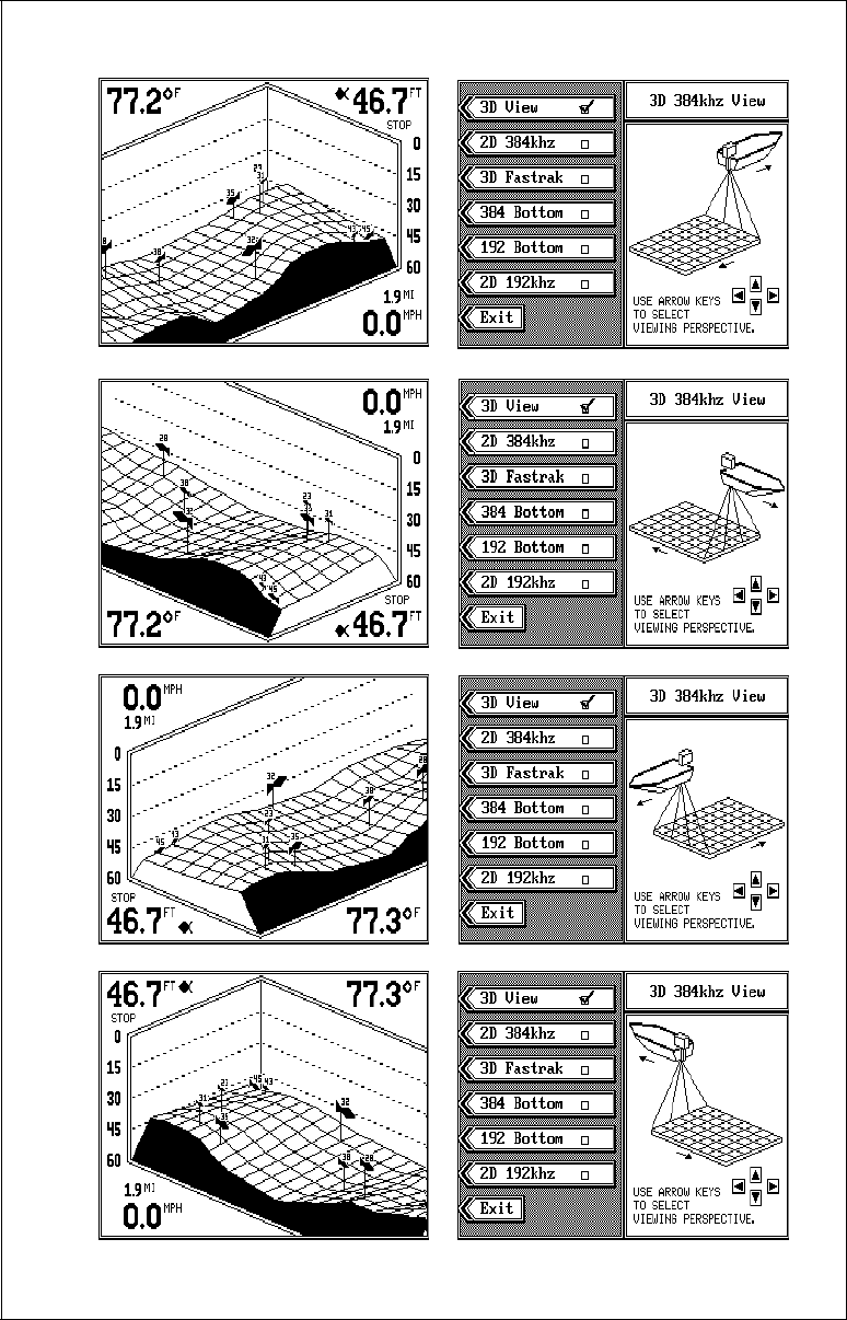
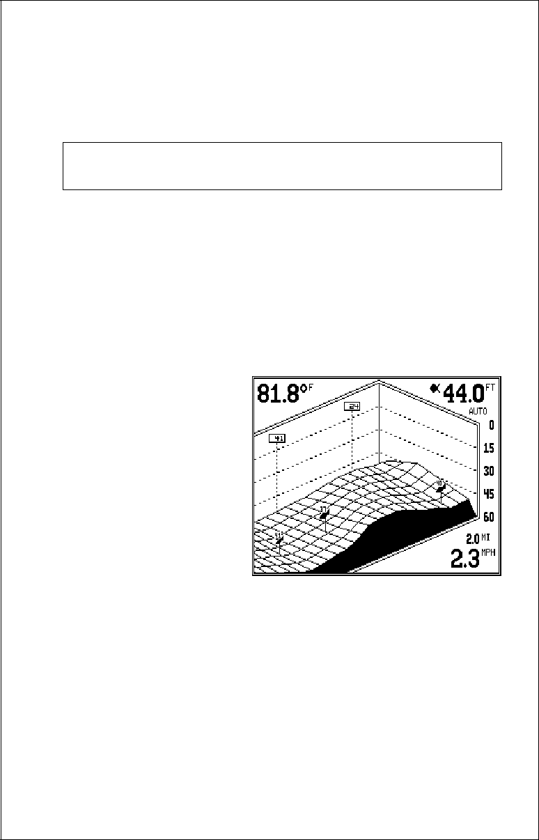
3D VARIVIEW™
When the X-70A 3D is first turned on, the 3D screen scrolls from right to
left as shown above. This view shows you the bottom contour as if your
boat is travelling from the left side of the screen to the right side. The
upper right corner of the screen is the right (starboard) side of your boat’s
transom. There are occasions when you may wish to change the viewing
angle of the bottom. For example, if you’re travelling parallel to a drop-off,
the far side of the drop-off may not be visible, due to the higher ground
obstructing the drop-off. By rotating the 3D view, the opposite side of the
drop-off can be seen.
To change the 3D view, first
press the WINDOWS key. The
screen shown at right appears.
There are four views available.
Press the arrow keys to rotate
the 3D view. When you’ve ro-
tated the display to the desired
view, press the CLR key to re-
turn to the 3D screen.
2D OPERATION
2D Transducer Element Se-
14
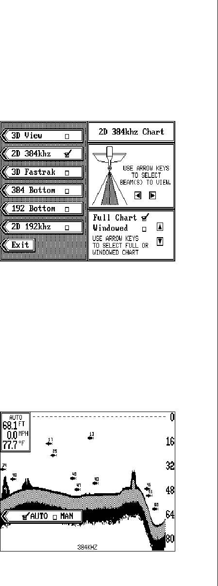
15
lection
This view shows all echoes in the traditional sonar graph display. You can
view echoes from any two 384 kHz transducer elements, or the 192 kHz
transducer. (Note: 192 kHz operation requires an optional 192 kHz trans-
ducer.) To select the transducer element and place the X-70A 3D into the
2D mode, press the WINDOWS key. Next, press the key next to the "2D
384 kHz" label or the "2D 192 kHz" label. The screen shown at right ap-
pears.
If you want to use only the cen-
ter two transducer elements,
simply press the CLR key to
switch to the 2D chart display.
As shown in the picture at
right, the shaded area beneath
the boat shows which trans-
ducer elements are in use.
When this unit is first turned
on, only the two center ele-
ments are in use for the 2D mode. To change to other elements, press the
left or right arrow keys. As you press the keys, the shaded area on the
screen moves also, showing you which transducer elements are in use.
Once you’ve selected the desired transducer elements, simply press the
CLR key to switch to the 2D chart display.
2D RANGE
The range is set by the unit as long as it’s in the auto mode. However, you
can adjust the range slightly when automatic is on. The unit won’t let you
move the bottom off the screen, and it will correct the range once the
bottom begins to go off the screen. When the unit is in the manual mode,
you can set the range to any
that’s available.
Automatic mode
To change the range, first
press the RANGE key. A
screen similar to the one at
right appears. Now press the
down arrow key to increase
the range or the up arrow key
to decrease it. When the de-
sired range is chosen, wait a
16
few seconds and the menu will automatically disappear from the screen
or press the CLR key to erase it.
Manual mode
When the X-70A 3D is in the manual mode, any range can be selected.
The unit will leave the range setting you choose, but it won't keep the
bottom on the display. For ex-
ample, if the range is 0 - 60
feet, and the bottom signal
goes from 55 to 70 feet, once
the bottom goes deeper than
60 feet, it won't show on the
display.
To change the range, first
press the RANGE key. A
screen similar to the one at
right appears. You can simply
use the up or down arrow keys
to select the range, or you can
use the upper and lower limit menus.
The X-70A 3D uses the following ranges: 0 - 5, 10, 20, 40, 60, 80, 100,
150, 200, 300, 400, 500, 700, and 900 feet.
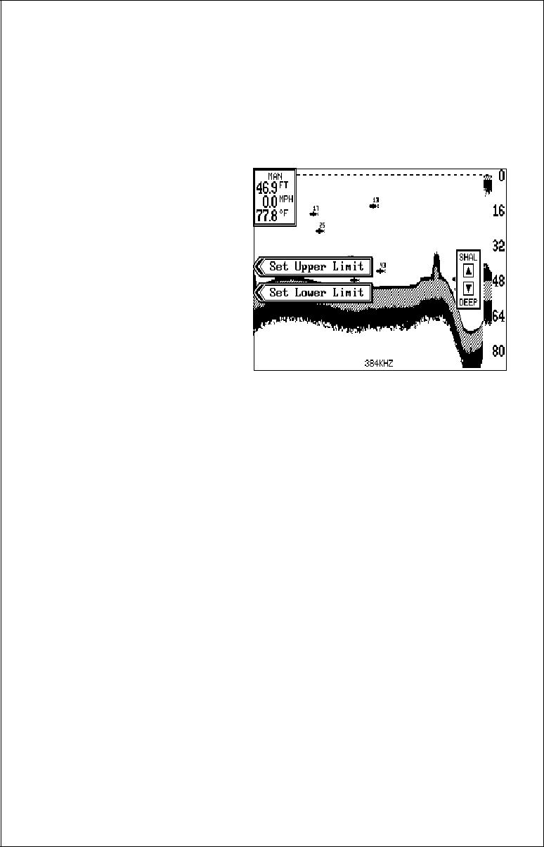
Upper and Lower Limits
The X-70A 3D gives you added versatility with the upper and lower limits
menu. The upper limit is the depth shown at the top of the screen, which is
normally zero. The lower limit is the depth shown at the bottom of the
screen which is normally a range such as 60 feet. By manually entering
the upper and lower limits, you can select any segment of the water using
increments as little as one foot! Changing the upper and lower limits in
this manner actually gives you a zoom in the manual mode that is much
more versatile than the standard zoom.
To change the upper limit, first make certain the unit is in the manual
mode, then press the RANGE key. Now press the key next to the "Set
Upper Limit" label. A screen similar to the one at the top of the next page
appears.
Now enter the upper limit, in any number as long as it's 10 feet or more
less than the lower limit. For example, if the range is 0 -60 feet, you can
use any number between 0 and 50 feet as an upper limit. After entering
the upper limit, press the ENT key. This returns the unit to the range menus
17
and your new upper limit will
be at the top of the screen.
To change the lower limit, use
the same steps as above, but
press the key next to the "Set
Lower Limit" menu.
Press the CLR key to erase
these menus or wait a few sec-
onds and they will automati-
cally disappear.
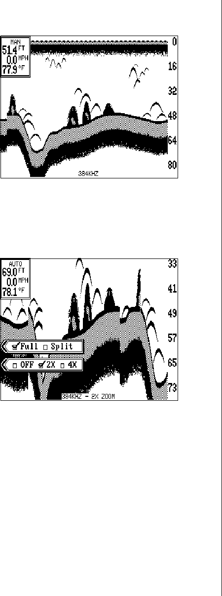
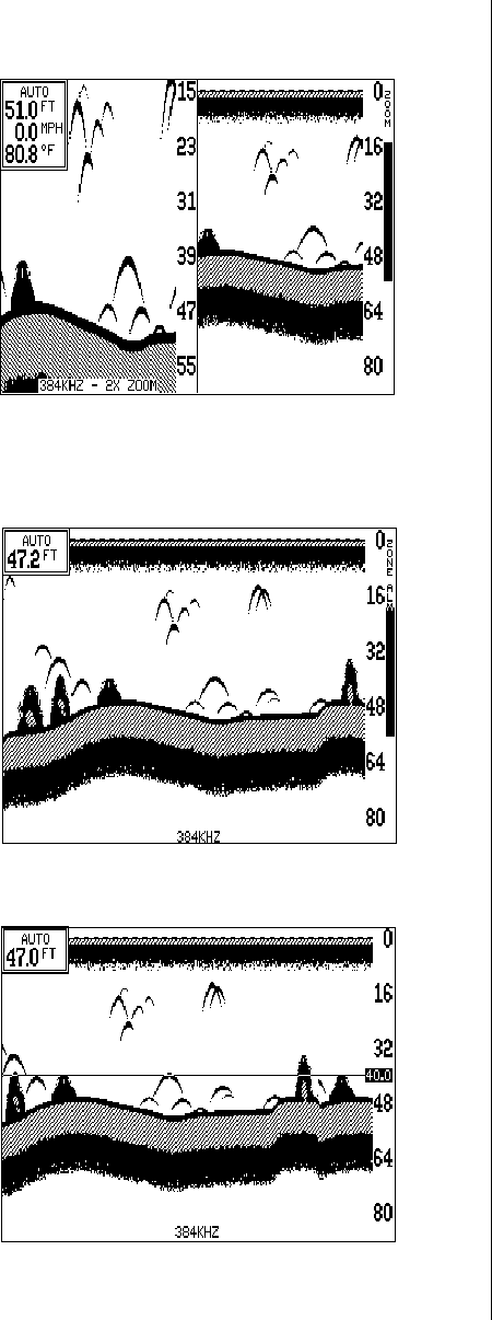
2D ZOOM - Automatic mode
The zoom feature enlarges all echoes on the screen, making them easier
to see. This feature works in automatic or the manual mode. The X-70A
3D can show a full 2D zoom screen or a split-screen with the right side
normal and the left side enlarged.
To use the zoom feature, first
press the ZOOM key. A screen
similar to the one at right ap-
pears. Now press the key next
to the "OFF 2X 4X" menu.
This switches the unit to the
2X zoom mode which en-
larges all echoes on the
screen to twice their normal
size. If you press the key again
while the menu is showing, the
unit will switch to the 4X zoom
mode. This enlarges all ech-
oes four times their normal size.
To use the split-screen zoom feature, press the key adjacent to the “FULL
SPLIT” label. This instantly divides the screen in half. The left half of the
screen is zoomed, the right side is a full-scale, top-to-bottom view of the
same area. The echoes that scroll across the screen are the same on
both sides of the screen, but they are enlarged and show in greater detail
on the left side. To switch back to full screen, press the ZOOM key, then
press the key next to the “FULL SPLIT” label.
Turn the zoom feature off by repeatedly pressing the ZOOM key until the
check mark is on the OFF box. Wait a few seconds for the menu to auto-
18
matically disappear from the screen or press the CLR key to erase it.
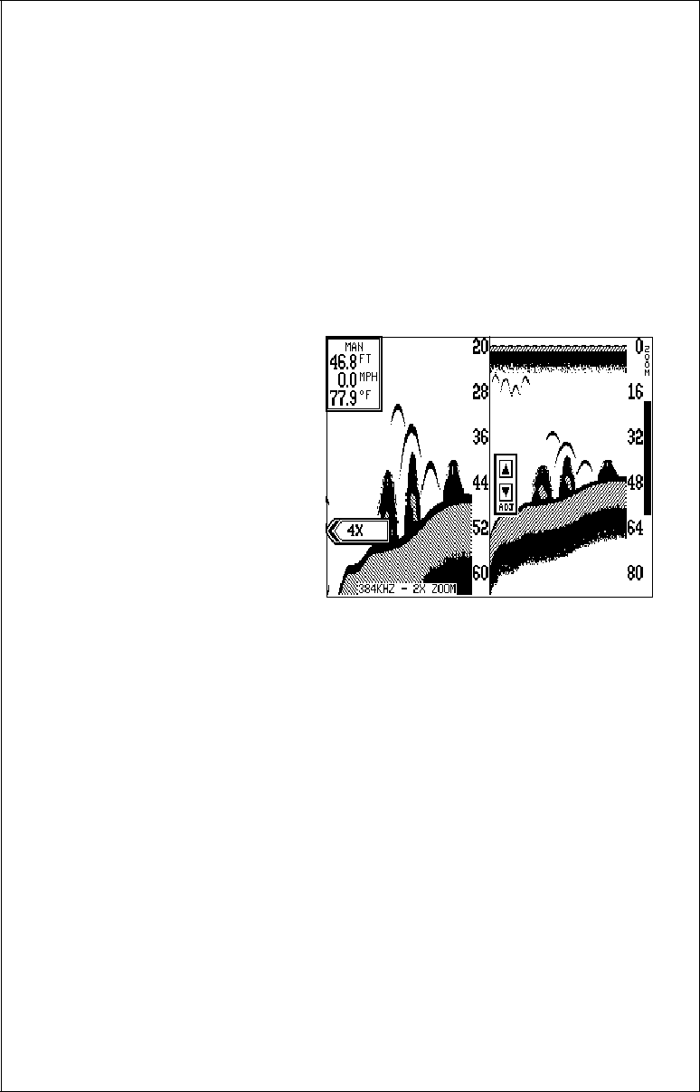
2D ZOOM - Manual Mode
The zoom feature works the same in manual as it does in automatic with
two exceptions. One, since the unit is in manual, the unit won’t change the
range to keep the bottom signal on the display. Two, you can adjust the
zoom “window” to any desired depth.
To zoom the screen in the manual mode, first press the ZOOM key. A
screen similar to the one on the previous page appears. You’ll notice a
new label on the screen: “ADJUST”. Press the key next to that label. A
screen similar to the one at right appears.
The unit is now in the split-
screen zoom mode. A zoom
bar is on the far right side of
the screen. Use the up and
down arrow keys to move this
bar up and down the right side
of the screen. Everything be-
tween the top and bottom of
this bar shows on the left side
of the screen in either 2X or
4X scale. When you have the
zoom bar in the desired loca-
tion, press the CLR key to erase it or wait a few seconds and it will auto-
matically disappear.
You can have the zoom bar stay on the screen continuously, by using the
zoom bar menu. See the 2D Options in the MENUS section for more
information.
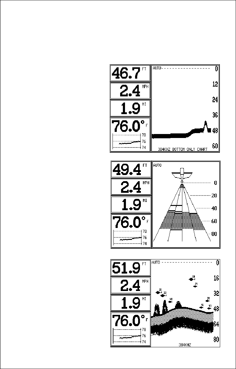
BOTTOM DEPTH VIEW
To use the Bottom Depth View, first press the WINDOWS key. Now press
the key next to the "384 Bottom" or "192 Bottom", depending on the trans-
ducer you wish to use or have installed. Finally, press the CLR key. A
screen similar to the one at the top of the next page appears.
This view shows the water depth in large digital numbers at the top left
corner of the screen. If an optional speed/temperature sensor is installed,
the unit can also show boat speed, distance travelled (log), surface water
temperature, and a surface water temperature graph in this area.
Next to the digital display box is the chart record. This shows depth infor-
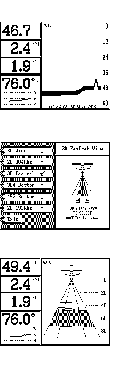
19
mation only. No fish, structure,
or any echoes other than the
bottom signal appear on this
screen. You can adjust the
range, however this is the only
adjustment you can make on
this screen. The X-70A 3D au-
tomatically sets the sensitivity
level.
FASTRAK™
The FasTrak™ view converts
all echoes to short horizontal
lines. Typically, the thicker the line, the stronger the signal. This view gives
you an immediate, “real-time” screen display. This high-speed display rep-
licates flasher performance. You can adjust sensitivity, range, and turn
automatic on or off in this
mode. Zoom is not available.
To use the Fastrak™ mode,
first press the WINDOWS key.
Now press the key next to the
"3D Fastrak" menu. A screen
similar to the one at right ap-
pears. When the X-70A 3D is
first turned on, only the cen-
ter two transducer elements
are in use. By pressing the left
or right arrow keys other ele-
ments can be selected. When you have the desired elements selected,
press the key next to the "Exit" menu. A screen similar to the one below
appears.
A representation of each of the
four transducer elements
shows on this screen. The digi-
tal displays are on the screen's
left side. Range scale numbers
are shown on the right side of
the transducer cone.
Echoes from each element
show in it’s respective cone.
Fish and other suspended tar-
20
gets appear as short, thin lines; usually for very short periods of time. The
bottom echo usually looks like a slice taken from the 2D screen. Surface
clutter appears at the top of the screen, near the picture of the boat.
Using the Fastrak screen combines the “instant read” of a flasher with the
versatility and convenience of a liquid crystal graph.
MENUS
The X-70A 3D uses menus
extensively to guide you
through the unit’s features. The
MENU key accesses most of
the these features, letting you
customize the unit to your par-
ticular water conditions. You
can exit from any menu by
pressing the CLR key.
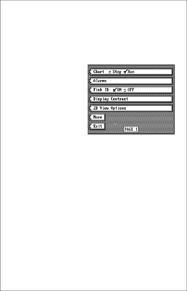
MENU - Page 1
CHART STOP
The X-70A 3D gives you the
ability to stop the chart for study. You can stop the chart no matter which
mode the unit is in - 3D, 2D, Bottom View, or FasTrack. (Note: Stopping
the chart doesn't stop the digital sonar. The digital depth display will con-
tinue to operate.)
To stop the chart or start it, press the MENU key, then press the key next
to the "Chart Stop Run" menu. Finally, press the key next to the "Exit"
label. The unit returns to the last used sonar display.
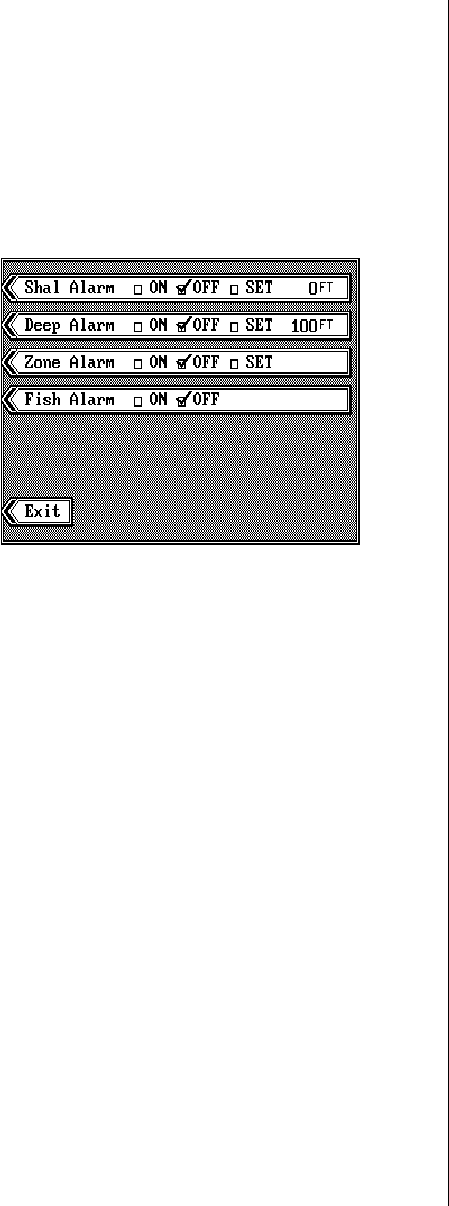
ALARMS
The X-70A 3D has three different alarms. The first is the Fish Alarm. It
sounds when the Fish I.D. feature places a fish symbol on the screen.
(This alarm only works in the 2D and 3D modes.) Another alarm is the
Zone Alarm which consists of a bar on the right side of the screen. Any
echo that appears inside of this bar triggers the alarm. The last alarm is
called the Depth Alarm. It actually consists of two alarms - shallow and
deep. Only the bottom signal can trigger these alarms. They are useful as
an anchor watch, a shallow water alert, or for navigation.
To adjust an alarm, first press the MENU key, then press the key next to
the "Alarms" label. The screen shown at the top of the next page appears.
Follow the instructions to set each alarm.
DEPTH ALARMS
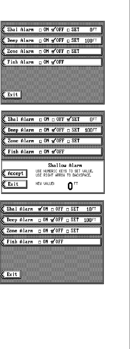
21
The depth alarms sound a
tone when the bottom signal
goes shallower than the shal-
low alarm’s setting or deeper
than the deep alarm’s setting.
For example, if you set the
shallow alarm to ten feet, the
alarm will sound a tone if the
bottom signal is less than ten
feet. It will continue to sound
until you mute it or the bottom
goes deeper than 10 feet. The
deep alarm works just oppo-
site. It sounds a warning tone
if the bottom depth goes
deeper than the alarm’s set-
ting. Both depth alarms work
only off the digital bottom
depth signals. No other tar-
gets will trip these alarms.
Both can be used at the same
time.
To set the depth alarms,
press the key adjacent to the
alarm you wish to set. In this
example, we will set and turn
on the shallow alarm. When
the X-70A 3D is turned on, the
shallow alarm is set to zero.
Pressing the key next to the
“Shal Alarm” menu moves the
check mark to the "SET" box.
This brings up the adjustment
menu, as shown above. Using
the numbered keys, enter the
depth for the shallow alarm. In
this example, we used 10 feet.
Press the key next to the “Ac-
cept” label. The screen returns to the alarm menu. The number you en-
tered shows on the shallow alarm’s menu. You’ll also notice that the check
mark in the shallow alarm’s menu has moved to the “ON” box. Setting an
alarm also turns it on. Press the CLR key to return to the sonar display.
Using our example, if the bottom signal goes lower than 10 feet, the shal-

22
low alarm sounds a tone.
To turn the shallow alarm off, press the MENU key, then press the key
next to the "Alarms" label. Now press the key next to the "Shal Alarm"
menu until the check mark moves to the “OFF” box. Press the CLR key to
return to the sonar display.
Remember, the shallow and deep alarms adjust exactly the same. The
only difference is the shallow alarm sounds when the bottom signal goes
shallower than the shallow alarm’s setting. The deep alarm sounds when
the bottom signal goes deeper than the deep alarm’s setting.
ZONE ALARM
The zone alarm only works on
the 2D chart or 2D FasTrak
view. Any echo that passes
inside the zone alarm’s bar
sets it off. To adjust the zone
alarm, first press the MENU
key, then press the key next
to the "Alarms" label. Now
press the key next to the
"Zone Alarm" label. A new
menu appears at the bottom
of the screen. Finally, press
the key next to the "Accept"
label. The screen shown above appears.
The zone alarm’s bar appears on the right side of the screen. Adjustment
menus show in the middle of the screen. Press the up or down arrow keys
to move the
bottom
of the zone alarm bar up or down. To adjust the top of
the zone alarm bar, first press the key adjacent to the "Adjust Upper"
label. After setting the zone alarm bar, press the CLR key to erase the
menus and bar or wait a few seconds and they will automatically clear.
(You can turn the zone alarm’s bar on continuously. See the 2D View
Options section for more information.)
Setting the zone alarm automatically turns it on. To turn it off, press the
ALARM key, then press the key next to the zone alarm’s menu. This moves
the check mark from "ON" to “OFF”. Press the CLR key to exit the alarm
menu.
23
FISH ALARM
The fish alarm sounds a distinctive tone when the X-70A 3D places a fish
symbol on the display. A different tone sounds for each of the four fish
symbol sizes.
To turn the fish alarm on, first press the MENU key, then press the key
next to the "Alarms" label. Finally, press the key next to the "Fish Alarm"
label. This moves the check
mark from the “OFF” box to the
“ON” box. Press the CLR key
to return to the sonar display.
To turn the fish alarm off, re-
peat the above steps.
(Note: The automatic and Fish
ID features must be on in or-
der to use the fish alarm. If you
turn the fish alarm on and
these other features are off,
the unit will automatically turn
them on.)
ALARM MUTE
Whenever a depth alarm sounds, a message appears on the display tell-
ing you which alarm is sounding. A “Silence Alarm” menu appears on the
display at the same time. Press the key next to this menu to mute or turn
the alarm’s sound off. This doesn’t turn the alarm off, only silences the
tone until the alarm is triggered again.
FISH I.D.
The Fish I.D. feature identifies targets that meet certain conditions as fish.
The microcomputer analyses all echoes and eliminates surface clutter,
thermoclines, and other signals that are undesirable. In most instances,
remaining targets are fish. The Fish I.D. feature displays symbols on the
screen in place of the actual fish echoes. There are four fish symbol sizes:
tiny, small, medium, and large. These are used to designate the relative
size between targets. In other words, it displays a small fish symbol when
it thinks a target is a small fish, a medium fish symbol on a larger target,
etc.
The microcomputer is sophisticated, but it can be fooled. It can’t distin-
guish between fish and other suspended objects such as trotlines, turtles,
submerged floats, air bubbles, etc. Individual tree limbs extending out-
wards from a group of limbs is the hardest object for the Fish I.D. feature
24
to distinguish from fish. You may see Fish I.D. symbols on the screen
when actually, there are no fish. Practice with the unit in both the Fish I.D.
mode and without to become more familiar with the Fish I.D. feature.
When the X-70A 3D is turned on, the Fish I.D. feature is automatically
turned on, also. To turn the
Fish I.D. feature off, press the
MENU key, then press the key
adjacent to the “Fish ID” label.
This moves the check mark
from the “ON” to the “OFF”
box. The unit returns to the
sonar display with Fish ID off.
To turn the Fish I.D. feature on
again, repeat the above steps.
The menu immediately disap-
pears and the sonar screen
returns. In the 2D mode, ech-
oes will continue to scroll
across the screen, however, the surface clutter at the top will no longer be
displayed. Any targets the microcomputer determines are fish will be dis-
played as fish symbols.
Remember, the Fish I.D. feature can’t be used when the X-70A 3D is in
the manual mode. If you turn the Fish I.D. feature on when the unit is in
manual, the microcomputer will turn the automatic feature on. If you turn
automatic off when the Fish I.D. feature is on, the Fish I.D. feature will be
turned off also.
DISPLAY CONTRAST
The unit’s display contrast is adjustable to suit different lighting condi-
tions. To adjust it, first press the MENU key. The first menu page appears.
Now press the key next to the
“Display Contrast” label. A
screen similar to the one at
right appears. Now press left
arrow key to decrease the
contrast. Press the right arrow
key to increase it. The percent-
age of contrast in use changes
as the arrow keys are pressed.
The bar chart also gives a
graphical indication of the con-
trast level. You can see the
FISH ID ON
25
change on the screen as you press the keys. After you’ve made the ad-
justment, press the CLEAR key to erase the menu.
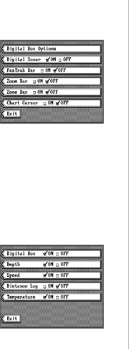
2D VIEW OPTIONS
The 2D view has several ad-
justments that (with some ex-
ceptions noted below) affect
the 2D view screen only. To
use these options, first press
the MENU key, then press the
key next to the “2D VIEW OP-
TIONS” label. A menu similar
to the one at right appears.
DIGITAL BOX OPTIONS
The X-70A 3D can display the depth, speed, surface water temperature,
and distance log on all sonar screens, including the 2D, 3D, Bottom Depth
View, and FasTrak. (Speed, temperature, and log displays require an op-
tional speed/temperature sensor.) When the X-70A 3D is first turned on,
only the depth is displayed if the sensor is not connected. You can turn
each digital display on as desired or turn all of them off, as desired.
To select the digital displays menu, first press the MENU key. Next, press
the key adjacent to the “2D View Options” label. Finally, press the key next
to the “Digital Box Options” menu. The screen shown below appears.
Now press the key adjacent to the desired display. For example, to turn
the temperature display on, press the key adjacent to the “TEMPERA-
TURE” label. Once you do this, the digital display in the corner of the
screen will show the temperature in addition to the depth. You can turn
each display on or off, individu-
ally.
If you wish to turn all of the
digital displays off, simply
press the key next to the
“DIGITAL BOX” label. Press
the CLEAR key to exit from
this menu.
DIGITAL SONAR
When the X-70A 3D’s 2D
26
screen is turned on for the first
time, the digital depth display
is located at the top left cor-
ner of the screen. This display
comes from a separate digital
sonar built into the unit. It dis-
plays only the bottom depth. If
it loses the bottom, the last
known depth will flash on the
display. When the digital finds
the bottom, it will automatically
display the bottom depth
again.
The digital sonar can be turned off, however this also turns all automatic
features off also, such as auto sensitivity, auto ranging, and the Fish I.D.
feature.
To turn the digital sonar off, first press the MENU key. Next, press the key
adjacent to the “2D View Options” label. Finally, press the key next to the
“Digital Sonar” menu. To turn it back on, repeat the same steps.
2D FASTRAK BAR
This feature converts all echoes to short horizontal lines on the 2D display’s
far right side. The graph continues to operate normally. FasTrak™ gives
you a rapid update of conditions directly under the boat. This makes it
useful for ice fishing, or when you’re fishing at anchor. Since the unit is not
moving, fish signals are long, drawn out lines on a normal chart display.
FasTrak™ converts the graph to a vertical bar graph that, with practice,
makes a useful addition to fishing at a stationary location.
To turn FasTrak™ on, first
press the MENU key. Next,
press the key adjacent to the
“2D View Options” label. Fi-
nally, press the key next to the
“FasTrak Bar” menu. To turn it
back on, repeat the same
steps.
ZOOM BAR
27
When the unit is in the 2D split-
screen zoom mode, the zoom
bar doesn’t normally show on
the screen. The zoom bar
shows the section of water on
the right side of the screen that
the zoom feature displays on
the left side. To turn the zoom
bar on continuously, first press
the MENU key. Next, press the
key adjacent to the “2D View
Optional” label. Finally, press
the key next to the “Zoom Bar”
menu. Press the CLR key to return to the sonar display. The zoom bar will
show on the far right side of the display when it’s in the 2D split-screen
zoom mode. To turn it off, repeat the same steps.
DISPLAY ZONE ALARM
BAR
When the zone alarm is on, the
zone bar doesn’t normally
show on the screen. To turn
the zone bar on continuously,
first press the MENU key. Next,
press the key adjacent to the
“2D View Options” label. Fi-
nally, press the key next to the
“Zone Bar” menu. Press the
CLR key to return to the sonar
display. The zoom bar will
show on the far right side of the display when it’s in the 2D mode. To turn
it off, repeat the same steps.
CHART CURSOR
The X-70A 3D has a chart cur-
sor that allows you to pinpoint
a target’s depth. The cursor is
simply a horizontal line that
extends across the display
from left to right. A depth box
at the end of the line on the
right side shows the line’s
depth. In the example at right,
the cursor (line) is at 16.4 feet.
28
To display the chart cursor, press the MENU key. Next, press the key
adjacent to the “2D View Options” label. Finally, press the key next to the
“Chart Cursor” menu. Press the CLR key to return to the sonar display.
Use the up or down arrow keys to move the cursor up or down to the
desired depth.
To turn the chart cursor off, repeat the above steps. The unit returns to the
sonar screen without the chart cursor.
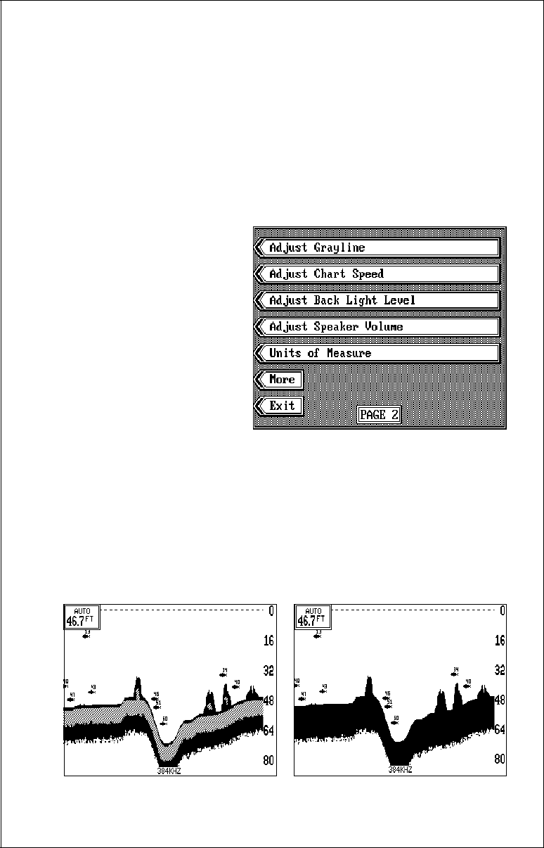
MENU - PAGE 2
GRAYLINE®
GRAYLINE® lets you distin-
guish between strong and
weak echoes. It “paints” gray
on targets that are stronger
than a preset value. This al-
lows you to tell the difference
between a hard and soft bot-
tom. For example, a soft,
muddy or weedy bottom re-
turns a weaker signal which is
shown with a narrow or no gray line. A hard bottom returns a strong signal
which causes a wide gray line.
If you have two signals of equal size, one with gray and the other without,
then the target with gray is the stronger signal. This helps distinguish weeds
from trees on the bottom, or fish from structure.
GRAYLINE® is adjustable. Since GRAYLINE® shows the difference be-
tween strong and weak signals, adjusting the sensitivity may require a
GRAYLINE® ON GRAYLINE® OFF
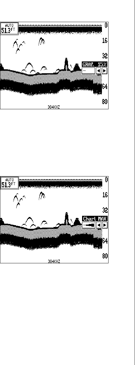
29
different GRAYLINE® level,
also. The level chosen by the
X-70A 3D is usually adequate
for most conditions. Experi-
ment with your unit to find the
GRAYLINE® setting that’s best
for you.
To adjust GRAYLINE®, press
the MENU key twice, then
press the key adjacent to the
“Adjust Grayline” label. A
screen similar to the one at
right appears. Now press the left arrow key to decrease the gray level.
Press the right arrow key to increase it. The percentage of GRAYLINE® in
use changes as the arrow keys are pressed. The bar chart also gives a
graphical indication of the GRAYLINE® level. You can see the change on
the screen (both on the menu and on the chart record) as you press the
keys. After you’ve made the adjustment, press the CLEAR key to erase
the menu.
CHART SPEED
The rate echoes scroll across
the screen is called the chart
speed. It’s adjustable by first
pressing the MENU key twice,
then pressing the key adjacent
to the “Adjust Chart Speed” la-
bel. The chart speed menu
appears on the screen's right
side. Increase the chart speed
by pressing the right arrow key
or decrease it by pressing the
left arrow key. The percentage
of chart speed in use changes as the arrow keys are pressed. The bar
chart also gives a graphical indication of the chart speed. You can see the
change on the screen (both on the menu and on the chart record) as you
press the keys. After you’ve made the adjustment, press the CLR key to
erase the menu.
BACK LIGHTS
The X-70A 3D has internal lights for the display and keyboard. To turn the
lights on, or off, simply press the “ON” key. To adjust the intensity of the
lighting, press the MENU key twice, then press the key adjacent to the
30
“Adjust Back Light Level” label.
The screen shown at right ap-
pears. Now press the left ar-
row key to decrease the light
level. Press the right arrow key
to increase it. The percentage
of back light in use changes
as the arrow keys are pressed.
The bar chart also gives a
graphical indication of the
level. After you’ve made the
adjustment, press the CLR
key to erase the menu.
SPEAKER VOLUME
To adjust the X-70A 3D's speaker volume, press the MENU key twice,
then press the key next to the “Adjust Speaker Volume” label. Now press
the left arrow key to decrease the level, the right arrow key to increase it.
The percentage of volume in use changes as the arrow keys are pressed.
The bar chart also gives a graphical indication of the level. After you’ve
made the adjustment, press the CLR key to erase the menu.
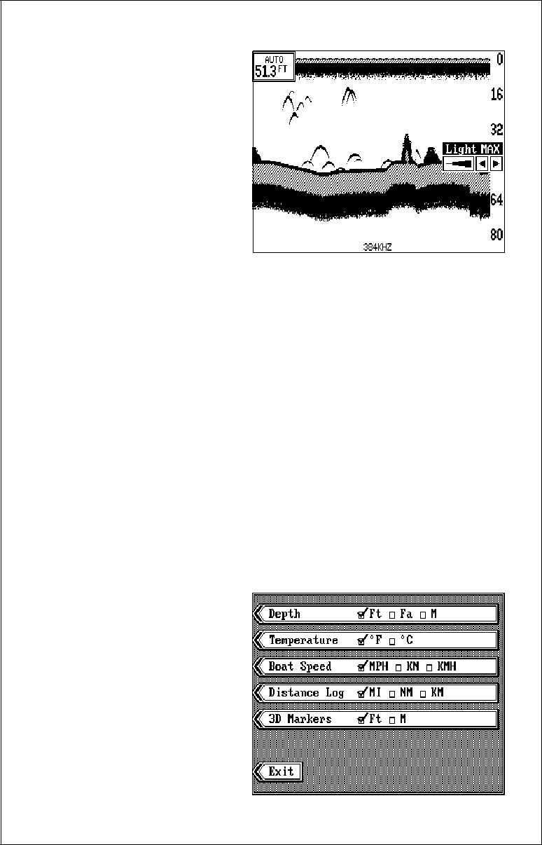
UNITS OF MEASURE
When the optional speed/temperature sensor is connected, the X-70A
3D can display the water depth in feet, fathoms, or meters, surface water
temperature in degrees Fahrenheit or Celsius, speed in statute miles per
hour, kilometers per hour, or knots, distance (log) in miles, kilometers, or
nautical miles, and the 3D distance markers in feet or meters.
To change the units of measure, first press the menu key two times. Next,
press the key adjacent to the “Units of Measure” label. The screen shown
below appears. The check
mark in the box on each line
shows the unit of measure
currently in use. In the screen
shown below, the units of mea-
sure are in feet for the depth,
temperature in degrees Fahr-
enheit, speed is in statute
miles per hour, and log is in
statute miles.
Press the key adjacent to the
unit that you wish to change.
31
For example, press the key next to the "Depth" label two times to switch
from feet to meters. This moves the check mark two times from the “Ft” to
the “M”.
After setting the units of measure, press the CLR key.
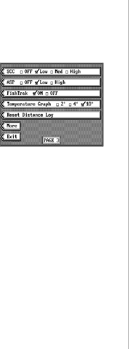
MENU - PAGE 3
SURFACE CLARITY
The markings extending
downward from the zero line
on the 2D chart when the
manual mode is on are called
“surface clutter.” These mark-
ings are caused by wave ac-
tion, boat wakes, temperature
inversion, and other natural
causes.
The Surface Clarity Control (SCC) reduces or eliminates surface clutter
signals from the display. SCC varies the sensitivity of the receiver, de-
creasing it near the surface and gradually increasing it as the depth in-
creases. The maximum depth that SCC will affect is 75% of the selected
depth range. For example, on a 0-60 foot range with maximum SCC, sur-
face clutter will be reduced down to about 45 feet.
There are three levels of SCC available on the X-70A 3D: low, medium,
and high. When it’s turned on for the first time, the SCC level is low. To
change it, press the MENU key three times, then press the key adjacent
to the “SCC” label until the check mark is on the desired SCC level. Press
the CLR key when you’re finished.
ASP (Advanced Signal Processing)
The ASP feature is a noise rejection system built into the X-70A 3D that
constantly evaluates the effects of boat speed, water conditions, and in-
terference. This automatic feature gives you the best display possible un-
der most conditions.
The ASP feature is an effective tool in combating noise. In sonar terms,
noise is any undesired signal. It is caused by electrical and mechanical
sources such as bilge pumps, engine ignition systems and wiring, air
bubbles passing over the face of the transducer, even vibration from the
engine. In all cases, noise can produce unwanted marks on the display.
32
The ASP feature has two lev-
els - Low and High. If you have
high noise levels, try using the
“High” ASP setting. However,
if you are having trouble with
noise, we suggest that you
take steps to find the interfer-
ence source and fix it, rather
than continually using the unit
with the high ASP setting.
However, there are times
when you may want to turn the
ASP feature off. This allows
you to view all incoming echoes before they are processed by the ASP
feature.
To change the ASP level, press the MENU key three times. Then press
the key next to the “ASP” label until the desired level is obtained. Press
the CLR key to exit this menu.
FISHTRACK™
When the X-70A 3D is in the
2D or 3D modes and the Fish
ID feature is on, the depth of
the fish symbols can easily be
determined using the
FishTrack™ feature. This
places the depth above the
fish symbol as it appears on
the screen. It is normally on
when the unit is turned on. To
turn the FishTrack™ feature
off, press the MENU key two
times. Now press the key next
to the “FishTrack” label. This moves the check mark from the “ON” box to
the “OFF” box. To turn it on again, repeat the above steps.
TEMPERATURE GRAPH ADJUSTMENT
The temperature graph that appears beneath the digital surface water
temperature display has a range from 5 degrees higher than the current
temperature to 5 degrees lower than the current temperature, for a total of
ten degrees. This range can be changed from ten to two or four degree. To
change the temperature graph range, press the MENU key three times,
then press the key next to the "Temperature Graph" label until the check
FISHTRACK ON
33
mark is on the desired range. Press the CLR key to exit the menu.
RESET DISTANCE LOG
The X-70A 3D can display the log (distance travelled) in the digital block if
the optional speed/temperature sensor is installed. This feature starts
counting distance as soon as the unit is turned on. To reset the distance
log to zero, press the MENU key three times, then press the key adjacent
to the “Reset Distance Log” label. Press the CLR key to return to the
sonar display.
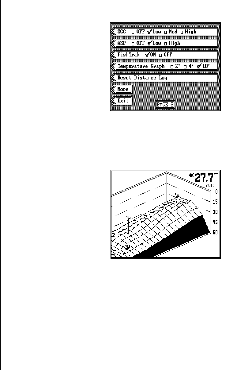
MENU - PAGE 4
3D ENHANCE
Although the X-70A 3D has
four transducer elements, the
display shows an enhanced
grid that adds points to the
grid. See the difference be-
tween the two screens shown
below. To remove the extra
lines and view only the depth
grid from the four elements,
first press the MENU key four
times. Now press the key next
to the “3D Enhance” label. The extra lines are erased from the display. To
turn the enhanced display on, simply repeat the above steps.
3D SCREEN ENHANCED 3D SCREEN NOT ENHANCED
34
3D SIMULATOR
The X-70A 3D has a built-in simulator for the 3D display. When this simu-
lator is turned on, a realistic 3D view scrolls across the screen. The digital
depth display shows the simulated bottom depth, and fish symbols ap-
pear on the display.
IMPORTANT!
Do not use the simulator when navigating!
To turn the 3D simulator on, press the MENU key four times. Now press
the key next to the “3D Simulator” label to move the check mark from the
“OFF” box to the “ON” box. If you return to the 3D screen, the simulator
will be in operation.
To turn the 3D simulator off, press the MENU key four times. Now press
the key next to the “3D Simulator” label to move the check mark from the
“ON” box to the “OFF” box. If you return to the 3D screen, the simulator
will be off.
3D DISTANCE MARKERS
The X-70A 3D displays mark-
ers on the screen, showing the
approximate distance echoes
are behind the boat. (This re-
quires an optional speed/tem-
perature sensor.) When the
unit is turned on, the markers
are automatically displayed if
the speed/temp sensor is
plugged in. If you wish to turn
the markers off, press the
MENU key four times, then
press the key next to the "3D
Distance Markers until the check mark moves to the "OFF" box. Press the
CLR key to exit.

35
TROUBLESHOOTING
If your unit is not working, or if you need technical help, please use the
following troubleshooting section before contacting the factory customer
service department. It may save you the trouble of returning your unit.
Unit won’t turn on:
1. Check the power cable’s connection at the unit. Also check the wiring.
2. Make certain the power cable is wired properly. The red wire connects
to the positive battery terminal, black to negative or ground.
3. Check the fuse.
4. Measure the battery voltage at the unit’s power connector. It should be
at least 11 volts. If it isn’t, the wiring to the unit is defective, the battery
terminals or wiring on the terminals are corroded, or the battery needs
charging.
Unit freezes, locks up, or operates erratically:
1. Electrical noise from the boat’s motor, trolling motor, or an accessory
may be interfering with the sonar unit. Rerouting the power and trans-
ducer cables away from other electrical wiring on the boat may help.
Route the sonar unit’s power cable directly to the battery instead of
through a fuse block or ignition switch
2. Inspect the transducer cable for breaks, cuts, or pinched wires.
3. Check both the transducer and power connectors. Make certain both
are securely plugged in to the unit.
Weak bottom echo, digital readings erratic, or no fish signals:
1. Make certain transducer is pointing straight down. Clean the face of
the transducer. Oil, dirt, and fuel can cause a film to form on the trans-
ducer, reducing its effectiveness.
2. Electrical noise from the boat’s motor can interfere with the sonar. This
causes the sonar to automatically increase its Discrimination or noise
rejection feature. This can cause the unit to eliminate weaker signals
such as fish or even structure from the display.
3. The water may be deeper than the sonar’s ability to find the bottom. If
the sonar can’t find the bottom signal while it’s in the automatic mode,
the digital will flash continuously. It may change the range to limits far
greater than the water you are in. If this happens, place the unit in the

36
manual mode, then change the range to a realistic one, (for example,
0-100 feet) and increase the sensitivity. As you move into shallower
water, a bottom signal should appear.
4. Check the battery voltage. If the voltage drops, the unit’s transmitter
power also drops, reducing its ability to find the bottom or targets.
Bottom echo disappears at high speeds or erratic digital reading or
weak bottom echo while boat is moving
1. The transducer may be in turbulent water. It must be mounted in a
smooth flow of water in order for the sonar to work at all boat speeds.
Air bubbles in the water disrupt the sonar signals, interfering with its
ability to find the bottom or other targets. The technical term for this is
Cavitation.
2. Electrical noise from the boat’s motor can interfere with the sonar. This
causes the sonar to automatically increase its Discrimination or noise
rejection feature. This can cause the unit to eliminate weaker signals
such as fish or even structure from the display. Try using resistor spark
plugs or routing the sonar unit’s power and transducer cables away
from other electrical wiring on the boat.
No fish arches when the Fish ID feature is off:
1. Make certain transducer is pointing straight down. This is the most
common problem if a partial arch is displayed.
2. The sensitivity may not be high enough. In order for the unit to display
a fish arch, it has to be able to receive the fish’s echo from the time it
enters the cone until it leaves. If the sensitivity is not high enough, the
unit displays the fish only when it is in the center of the cone.
3. Use the Zoom feature. It is much easier to display fish arches when
zoomed in on a small range of water than a large one. For example,
you will have much better luck seeing fish arches with a 30 to 60 foot
range than a 0 to 60 foot range. This enlarges the targets, allowing the
display to show much more detail.
4. The boat must be moving at a slow trolling speed to see fish arches. If
the boat is motionless, fish stay in the cone, showing on the display as
straight horizontal lines.

37
NOISE
A major cause of sonar problems is electrical noise. This usually appears
on the sonar’s display as random patterns of dots or lines. In severe cases,
it can completely cover the screen with black dots, or cause the unit oper-
ate erratically, or not at all.
To eliminate or minimize the effects of electrical noise, first try to deter-
mine the cause. With the boat at rest in the water, the first thing you should
do is turn all electrical equipment on the boat off. Make certain the engine
is off, also. Turn your X-70A 3D on, then turn off ASP (Advanced Signal
Processing). There should be a steady bottom signal on the display. Now
turn on each piece of electrical equipment on the boat and view the effect
on the sonar’s display. For example, turn on the bilge pump and view the
sonar display for noise. If no noise is present, turn the pump off, then turn
on the VHF radio and transmit. Keep doing this until all electrical equip-
ment has been turned on, their effect on the sonar display noted, then
turned off.
If you find noise interference from an electrical instrument, trolling motor,
pump, or radio, try to isolate the problem. You can usually reroute the
sonar unit’s power cable and transducer cable away from the wiring that
is causing the interference. VHF radio antenna cables radiate noise when
transmitting, so be certain to keep the sonar’s wires away from it. You may
need to route the sonar unit’s power cable directly to the battery to isolate
it from other wiring on the boat.
If no noise displays on the sonar unit from electrical equipment, then make
certain everything except the sonar unit is turned off, then start the en-
gine. Increase the RPM with the gearshift in neutral. If noise appears on
the display, the problem could be one of three things; spark plugs, alter-
nator, or tachometer wiring. Try using resistor spark plugs, alternator fil-
ters, or routing the sonar unit’s power cable away from engine wiring.
Again, routing the power cable directly to the battery helps eliminate noise
problems. Make certain to use the in-line fuse supplied with the unit when
wiring the power cable to the battery.
When no noise appears on the sonar unit after all of the above tests, then
the noise source is probably cavitation. Many novices or persons with
limited experience make hasty sonar installations which function perfectly
in shallow water, or when the boat is at rest. In nearly all cases, the cause
of the malfunction will be the location and/or angle of the transducer. The
face of the transducer must be placed in a location that has a smooth flow
of water at all boat speeds.

39
LOWRANCE ELECTRONICS
FULL ONE-YEAR WARRANTY
“We", “our”, or “us” refers to LOWRANCE ELECTRONICS, INC., the manufacturer of this
product. “You” or “your” refers to the first person who purchases this product as a consumer
item for personal, family, or household use.
We warrant this product against defects or malfunctions in materials and workmanship, and
against failure to conform to this product’s written specifications, all for one year (1) from the
date of original purchase by you. WE MAKE NO OTHER EXPRESS WARRANTY OR
REPRESENTATION OF ANY KIND WHATSOEVER CONCERNING THIS PRODUCT.
Your remedies under this warranty will be available so long as you can show in a reasonable
manner that any defect or malfunction in materials or workmanship, or any non-conformity
with the product’s written specifications, occurred within one year from the date of your
original purchase, which must be substantiated by a dated sales receipt or sales slip. Any
such defect, malfunction, or non-conformity which occurs within one year from your original
purchase date will either be repaired without charge or be replaced with a new product
identical or reasonably equivalent to this product, at our option, within a reasonable time after
our receipt of the product. If such defect, malfunction, or non-conformity remains after a
reasonable number of attempts to repair by us, you may elect to obtain without charge a
replacement of the product or a refund for the product. THIS REPAIR, REPLACEMENT, OR
REFUND (AS JUST DESCRIBED) IS THE EXCLUSIVE REMEDY AVAILABLE TO YOU
AGAINST US FOR ANY DEFECT, MALFUNCTION, OR NON-CONFORMITY CONCERN-
ING THE PRODUCT OR FOR ANY LOSS OR DAMAGE RESULTING FROM ANY OTHER
CAUSE WHATSOEVER. WE WILL NOT UNDER ANY CIRCUMSTANCES BE LIABLE
TO ANYONE FOR ANY SPECIAL, CONSEQUENTIAL, INCIDENTAL, OR OTHER INDI-
RECT DAMAGE OF ANY KIND.
Some states do not allow the exclusion or limitation of incidental or consequential damages,
so the above limitations or exclusions may not apply to you.
This warranty does NOT apply in the following circumstances: (1) when the product has
been serviced or repaired by anyone other than us, (2) when the product has been
connected, installed, combined, altered, adjusted, or handled in a manner other than
according to the instructions furnished with the product, (3) when any serial number has
been effaced, altered, or removed, or (4) when any defect, problem, loss, or damage has
resulted from any accident, misuse, negligence, or carelessness, or from any failure to
provide reasonable and necessary maintenance in accordance with the instructions of the
owner’s manual for the product.
We reserve the right to make changes or improvements in our products from time to time
without incurring the obligation to install such improvements or changes on equipment or
items previously manufactured.
This warranty gives you specific legal rights and you may also have other rights which may
vary from state to state.
REMINDER: You must retain the sales slip or sales receipt proving the date of your original
purchase in case warranty service is ever required.
(800) 324-1356
12000 E. SKELLY DRIVE TULSA, OK 74128
LOWRANCE ELECTRONICS

40
Lowrance's UPS Return Service
Lowrance Electronics and United Parcel Service (UPS) are proud to offer
all of our customers free shipping for all units sent to us for repair or service.
If you have to send this unit to the factory, and you are in the continental
United States, use the enclosed UPS shipping label for easy, free shipping
to our factory customer service department. There are six easy steps:
1.Call Lowrance at the toll-free number on the front of this flyer for a Return
Authorization (RA) number and instructions about what accessories to
return. Do not return a product to the factory without a Return
Authorization (RA) Number!
2.Pack your unit and any accessories in the original shipping container, if
possible. Be sure to include proof of purchase for warranty verifica-
tion!
3. Write a brief note detailing the problem you're having with the unit.
Please include your name, address, and daytime telephone number.
4. Please include payment for non-warranty repairs. Check, money order,
Visa, or MasterCard may be used.
5.Fill in your name, address, zip code, date, and RA number in the blanks
provided on the UPS form included with your unit.
6.Attach the label to the shipping box, tear off the tab for your receipt and
give the package to any UPS driver or take the package to any UPS
Customer Center. You will not be charged for this shipment.
That's it! Your unit will be shipped to Lowrance's customer service
department at no charge to you. Units under warranty will be returned to
you at no charge.
NOTE!
Lowrance will pay UPS surface shipping charges both to and from the
factory for this unit in the event it needs repair. Your unit is insured against
loss or shipping damage when you use the enclosed UPS label.

41
This UPS shipping offer is good only in the continental United States (excludes Alaska and Hawaii).
KEEP THIS LABEL!
YOU WILL NEED IT IF YOU EVER NEED TO RETURN YOUR UNIT TO THE
FACTORY FOR REPAIR.
Accessory Ordering Information
To order accessories such as power cables or transducers, please contact:
1) Your local marine dealer. Most quality dealers that handle marine
electronic equipment should be able to assist you with these items.
Consult your local telephone directory for listings.
2) LEI Extras, Inc. P.O. Box 129 Catoosa, OK 74015-0129
or call
800-324-0045
(USA orders only.)
Lowrance Electronics may find it necessary to change or end our shipping policies,
regulations, and special offers at any time. We reserve the right to do so without notice.

43
How to Obtain Service
(Canadian Customers Only)
We back your investment in quality products with quick, expert service and genuine
Lowrance replacement parts. If you need service or repairs, contact the Lowrance
Factory Customer Service Department at the toll-free number listed below. A technician
may be able to solve the problem and save you the inconvenience of returning your unit.
You will be asked for your unit's serial number.
800-347-1014
Canada Only. Monday through Friday 8:00 A.M. - 8:00 P.M. Central Time.

44
LITHO IN U.S.A. 988-0133-18
How to Obtain Service - U.S.A. Only
We back your investment in quality products with quick, expert service and
genuine Lowrance® replacement parts. If you're in the United States and
you have questions, please contact the Factory Customer Service Depart-
ment using our toll-free number listed below. You must send the unit to
the factory for warranty service or repair. Please call the factory before
sending the unit. You will be asked for your unit's serial number (shown
above). Use the following toll-free number:
800-324-1356
U.S.A.only. Monday through Friday 8:00 A.M. - 8:00 P.M. Central time, except holidays.
Your unit is covered by a full one-year warranty. (See the back of this flyer
for complete warranty details.) If your unit fails and the failure is not covered
by the original warranty, Lowrance has a flat-rate repair policy that covers
your unit and accessories packed with the unit at the factory. There is a
180-day warranty on all non-warranty repairs from the factory, which is
similar to the original warranty, but is for 180 days rather than one year. For
further details, please call us at the above number.
Lowrance also gives you free UPS shipping from anywhere in the continen-
tal United States both to and from the factory for all warranty repairs. You
can also use the enclosed UPS shipping label for non-warranty shipments.
See the inside of this flyer for more information.
Remember, non-warranty repairs are subject to Lowrance's published flat-
rate charges and 180-day warranty.
