Lucent Technologies Server System 85 Users Manual DEFINITY ECS And 75 & Terminals Adjuncts Reference
PDF DEFINITY ECS 8-2 Terminals and Adjuncts Reference T E X T F I L E S
Definity Enterprise R 8-2 Terminals and Adjuncts Reference Definity Enterprise R 8-2 Terminals and Adjuncts Reference
System 85 to the manual ad307025-c908-45f7-9b8a-74d1be0b0658
2015-02-02
: Lucent-Technologies Lucent-Technologies-Lucent-Technologies-Server-System-85-Users-Manual-436364 lucent-technologies-lucent-technologies-server-system-85-users-manual-436364 lucent-technologies pdf
Open the PDF directly: View PDF ![]() .
.
Page Count: 804 [warning: Documents this large are best viewed by clicking the View PDF Link!]
- ==============
- MAIN MENU
- ==============
- DEFINITY® ECS and System 75 and System 85 Terminals and Adjuncts Reference
- Contents
- 1 Introduction
- 2 General Information
- 3 Exposed Port Protection
- 4 Adjunct Power
- 5 Administration
- 6 Voice Terminal Features
- 7 The 6400 Series Telephones
- The 6402 and 6402D Telephones
- Applications
- Physical Features
- Dimensions
- Features
- Other Physical Features
- Wiring Information
- Appropriate Circuit Packs and Distance Limitations
- Power Requirements
- Administration
- Button Numbering
- Power Failure Operation
- FCC Registration
- UL and CSA Approval
- Hearing Aid Compatible
- 6402 and 6402D Equipment PECs and Comcodes
- Adjuncts
- Headsets
- Additional Documents
- The 6408+ and 6408D+ Telephones
- Applications
- Physical Features
- Dimensions
- Features
- Other Physical Features
- Wiring Information
- Appropriate Circuit Packs and Distance Limitations
- Power Requirements
- Administration
- Button Numbering
- Power Failure Operation
- FCC Registration
- UL and CSA Approval
- Hearing Aid Compatible
- 6408 Telephones and Equipment PECs and Comcodes
- Adjuncts
- Headsets
- Additional Documents
- The 6416D+ and 6416D+M Telephones
- All 6416D+ and 6416D+M Telephones
- Only the Modular 6416D+M Telephone
- Applications
- All 6416D+ and 6424D+M Telephones
- Applications for the Modular 6416D+M Telephone Only
- Physical Features
- Dimensions
- Features
- Other Physical Features
- Wiring Information
- Appropriate Circuit Packs and Distance Limitations
- Power Requirements
- Administration
- Button Numbering
- Administering the Analog Adjunct on the Modular 6416D+M Telephone
- Power Failure Operation
- FCC Registration
- UL and CSA Approval
- Hearing Aid Compatible
- 6416D+ and 6416D+M Telephones and Equipment PECs and Comcodes
- Adjuncts
- Headsets
- Additional Documents
- The 6424D+ and 6424D+M Telephone
- All 6424D+ and 6424D+M Telephones
- Only the Modular 6424D+M
- Applications
- All 6424D+ and 6424D+M Telephones
- Applications for the Modular 6424D+M Telephones Only
- Physical Features
- Dimensions
- Features
- Other Physical Features
- Wiring Information
- Appropriate Circuit Packs and Distance Limitations
- Power Requirements
- Administration
- Button Numbering
- Administering the Analog Adjunct on the Modular 6424D+M Telephone
- Power Failure Operation
- FCC Registration
- UL and CSA Approval
- Hearing Aid Compatible
- 6424D+ and 6424D+M Equipment PECs and Comcodes
- Adjuncts
- Headsets
- Additional Documents
- The 6402 and 6402D Telephones
- 8 The 7100 Series Voice Terminals
- 9 The 7200 Series Voice Terminals
- 10 The 7300 Series Voice Terminals
- 11 The 7400 Series Voice Terminals
- The 7401D and 7401 Plus Voice Terminals
- Applications
- Special Operational Characteristics
- Physical Features
- Dimensions
- Features
- Other Physical Features
- Distance Limitations
- Power Requirements
- Switch Administration
- Aliasing
- Button Numbering
- Power Failure Operation
- FCC Registration
- UL and CSA Approval
- Hearing Aid Compatible
- 7401D Equipment PECs and Comcodes
- 7401 Plus Equipment with PECs and Comcodes
- Adjuncts
- Headsets
- Additional Documents
- The 7402 Plus Voice Terminal
- Applications
- Physical Features
- Dimensions
- Features
- Other Physical Features
- Distance Limitations
- Power Requirements
- Switch Administration
- Aliasing
- Button Numbering
- Power Failure Operation
- FCC Registration
- UL and CSA Approval
- Hearing Aid Compatible
- 7402 Plus Equipment PECs and Comcodes
- Adjuncts
- Headsets
- Additional Documents
- The 7403D Voice Terminal
- The 7404D Voice Terminal
- The 7405D Voice Terminal
- The 7406D, 7406BIS, and 7406 Plus Voice Terminals
- Applications
- Physical Description
- Dimensions
- Feature Buttons
- Other Physical Features
- Distance Limitations
- Power Requirements
- Switch Administration
- Aliasing
- Button Numbering
- Power Failure Operation
- FCC Registration
- UL and CSA Approval
- Hearing Aid Compatibility
- 7406D/7406BIS Equipment PECs and Comcodes
- 7406 Plus Equipment PECs and Comcodes
- Adjuncts
- Headsets
- Additional Documents
- The 7407D, Enhanced 7407D, and 7407 Plus Voice Terminals
- Applications
- Special Operational Characteristics
- Switch Options for the 7407D and Enhanced 7407D
- DIP Switch Options for the 7407 Plus
- Physical Features
- Dimensions
- Features
- Other Physical Features
- Distance Limitations
- Power Requirements
- Switch Administration
- Aliasing
- Button Numbering
- Power Failure Operation
- FCC Registration
- UL and CSA Approval
- Hearing Aid Compatible
- 7407D/Enhanced 7407D Equipment PECs and Comcodes
- 7407 Plus Equipment PECs and Comcodes
- Adjuncts
- Headsets
- Additional Documents
- The 7410D and 7410 Plus Voice Terminals
- Applications
- Physical Description
- Dimensions
- Features
- Other Physical Features
- Distance Limitations
- Power Requirements
- Switch Administration
- Aliasing
- Button Numbering
- Power Failure Operation
- FCC Registration
- UL and CSA Approval
- Hearing Aid Compatible
- 7410D Equipment with PECs and Comcodes
- 7410 Plus Equipment PECs and Comcodes
- Adjuncts
- Headsets
- Additional Documents
- The 7434D Voice Terminal
- The 7444 Voice Terminal
- Applications
- Physical Description
- Dimensions
- Features
- Other Physical Features
- Distance Limitations
- Power Requirements
- Switch Administration
- Aliasing
- Button Numbering
- Power Failure Operation
- FCC Registration
- UL and CSA Approval
- Hearing Aid Compatible
- 7444 Equipment PECs and Comcodes
- Adjuncts
- Headsets
- Additional Documents
- The 7401D and 7401 Plus Voice Terminals
- 12 The 8400 Series Voice Terminals
- The 8403 Voice Terminal
- Applications
- Physical Features
- Dimensions
- Features
- Other Physical Features
- Color Options
- Wiring Information
- Distance Limitations
- Power Requirements
- Switch Administration
- Aliasing
- Button Numbering
- Power Failure Operation
- FCC Registration
- UL and CSA Approval
- Hearing Aid Compatible
- 8403 Equipment PECs and Comcodes
- Adjuncts
- Headsets
- Additional Documents
- The 8405B, 8405B Plus, 8405D, and 8405D Plus Voice Terminals
- Applications
- Physical Features
- Dimensions
- Features
- Other Physical Features
- Wiring Information
- Distance Limitations
- Power Requirements
- Switch Administration
- Aliasing
- Button Numbering
- Power Failure Operation
- FCC Registration
- UL and CSA Approval
- Hearing Aid Compatible
- 8405 Equipment PECs and Comcodes
- Adjuncts
- Headsets
- Additional Documents
- The 8410 Voice Terminal
- Applications
- Physical Features
- Dimensions
- Features
- Other Physical Features
- Wiring Information
- Distance Limitations
- Power Requirements
- Switch Administration
- Aliasing
- Button Numbering
- Power Failure Operation
- FCC Registration
- UL and CSA Approval
- Hearing Aid Compatible
- 8410 Equipment PECs and Comcodes
- Adjuncts
- Headsets
- Additional Documents
- The 8411 Voice Terminal
- Applications
- Physical Features
- Dimensions
- Features
- Other Physical Features
- PassageWay and Analog Adjunct Connections
- Wiring Information
- Distance Limitations
- Power Requirements
- Switch Administration
- Aliasing
- Button Numbering
- Administering the Analog Adjunct
- Power Failure Operation
- FCC Registration
- UL and CSA Approval
- Hearing Aid Compatible
- 8411 Equipment PECs and Comcodes
- Adjuncts
- Headsets
- Additional Documents
- The 8434 and 8434DX Voice Terminals
- Applications
- Physical Description
- Dimensions
- Features
- Other Physical Features
- Wiring Information
- Distance Limitations
- Power Requirements
- Switch Administration
- Aliasing
- Button Numbering
- Power Failure Operation
- FCC Registration
- UL and CSA Approval
- Hearing Aid Compatible
- 8434 and 8434DX Equipment PECs and Comcodes
- Adjuncts
- Headsets
- Additional Documents
- The 8403 Voice Terminal
- 13 CALLMASTER Voice Terminals
- The CALLMASTER, CALLMASTER II, CALLMASTER III, CALLMASTER IV, CALLMASTER V, and CALLMASTER VI Voi...
- Applications
- Special Operational Characteristics
- The Recorder Interface
- Physical Description
- Dimensions
- Features
- LOG IN and RELEASE buttons
- Self-Test
- Display
- Other Physical Features
- Wiring Information on the CALLMASTER IV
- Wiring Note for the CALLMASTER VI
- Distance Limitations
- Distance Limitations for the CALLMASTER V and CALLMASTER VI
- Power Requirements
- Switch Administration
- Button Numbering
- Power Failure Operation
- FCC Registration
- CALLMASTER Equipment PECs and Comcodes
- Adjuncts
- Headsets
- Additional Documents
- The CALLMASTER, CALLMASTER II, CALLMASTER III, CALLMASTER IV, CALLMASTER V, and CALLMASTER VI Voi...
- 14 The 500 and 2500 Series Telephones
- The 500 Series Telephone
- The 2500 Series Telephones
- The 2500 DMGC Telephone
- The 2500 YMGK Telephone
- The 2500 MMGL and 2500 YMGL, 2500 MMGM and 2500 YMGM, and 2554 MMGM and 2554 YMGM Telephones
- Applications
- Physical Description
- Dimensions
- Features on the 2500 YMGL, 2500 YMGM, and 2554 YMGM Telephones
- Other Physical Features (on All of these 2500 and 2554 Telephones)
- Distance Limitations
- Power Requirements
- Switch Administration
- Power Failure Operation
- FCC Registration
- UL and CSA Approval
- Hearing Aid Compatible
- 2500 MMGL and 2500 YMGL Equipment PECs
- Additional Documents
- The 2500 MMGN and 2500 YMGP and 2554 MMGN and 2554 YMGP Telephones
- Applications
- Physical Description
- Dimensions
- Features on the 2500 YMGP and 2554 YMGP Telephones
- Other Physical Features (on All of these 2500 and 2554 Telephones)
- Distance Limitations
- Power Requirements
- Switch Administration
- Power Failure Operation
- FCC Registration
- UL and CSA Approval
- Hearing Aid Compatible
- 2500 MMGN and 2500 YMGP Equipment PECs
- Additional Documents
- 15 The 6200 Series Telephones
- 16 The 8100 Series Telephones
- The 8101 and 8101M Telephones
- The 8102 and 8102M Telephones
- Applications
- Physical Description
- Dimensions
- Feature Buttons
- Other Physical Features
- Distance Limitations
- Power Requirements
- Switch Administration
- Administration of Hidden Features
- Power Failure Operation
- Ringer Equivalency Numbers
- FCC Registration
- Hearing Aid Compatible
- 8102 and 8102M Telephones PECs and Comcodes
- Adjuncts
- Additional Documents
- The 8110 and 8110M Telephones
- Applications
- Physical Description
- Dimensions
- Features
- Other Physical Features
- Distance Limitations
- Power Requirements
- Switch Administration
- Administration of Hidden Features
- Power Failure Operation
- Ringer Equivalency Numbers
- FCC Registration
- Hearing Aid Compatible
- 8110 and 8110M Telephones Equipment PECs and Comcodes
- Adjuncts
- Additional Documents
- 17 ISDN Voice Terminals
- The ISDN 7505 Modular Terminal
- The ISDN 7506 Voice Terminal
- The ISDN 7507 Display Terminal
- The ISDN 8503 Voice Terminal
- Applications
- Physical Description
- Dimensions
- Features
- Other Physical Features
- Distance Limitations
- Power Requirements
- Phantom or Auxiliary Power
- Terminating Resistors
- Switch Administration
- Power Failure Operation
- FCC Registration
- Hearing Aid Compatible
- 8503T Equipment PECs and Comcodes
- Adjuncts
- Headsets
- Additional Documents
- The ISDN 8510 Voice/Data Terminal
- Applications
- Physical Description
- Dimensions
- Features
- Other Physical Features
- Data Features
- Distance Limitations
- Power Requirements
- Phantom or Auxiliary Power
- Terminating Resistors
- Switch Administration
- Button Numbering
- The Service Profiler ID (SPID)
- Hidden/Craft Features
- Power Failure Operation
- FCC Registration
- Hearing Aid Compatible
- 8510T Equipment PECs and Comcodes
- Adjuncts
- Headsets
- Additional Documents
- The ISDN 8520T Voice/Data Terminal
- Applications
- Physical Description
- Dimensions
- Features
- Other Physical Features
- Data Features
- Distance Limitations
- Power Requirements
- Auxiliary Power Supply
- Terminating Resistor
- Switch Administration
- Button Numbering
- The Service Profiler ID (SPID)
- Hidden/Craft Features
- Power Failure Operation
- FCC Registration
- Hearing Aid Compatible
- 8520T Equipment PECs and Comcodes
- Adjuncts
- Headsets
- Additional Documents
- 18 Cordless and Wireless Telephones
- The MDC 9000 Cordless Telephone
- Applications
- Physical Features
- Dimensions
- Handset Features
- Charging Base Features
- Display Information
- Out-of-Range Indication
- Distance and Installation Limitations (for the Charging Base)
- Switch Administration
- Aliasing
- Button Numbering
- FCC Registration
- Hearing Aid Compatibility
- MDC 9000 Equipment PECs and Comcodes
- Additional Documents
- The MDW 9000 Wireless Telephone
- Applications
- Physical Features
- Dimensions
- Handset Features
- Charging Cradle Features
- Radio Module Features
- Display Information
- Out-of-Range Indication
- Distance and Installation Limitations
- Switch Administration
- Aliasing
- Button Numbering
- FCC Registration
- Hearing Aid Compatibility
- UL and CSA Approval
- MDW 9000 Equipment PECs and Comcodes
- Additional Documents
- The MDW 9031DCP Wireless Pocket Phone
- Applications
- Physical Features
- Dimensions
- Handset Features
- Battery Charger Features
- Radio Module Features
- Out-of-Range Indication
- Distance and Installation Limitations
- Switch Administration
- Aliasing
- Button Numbering
- FCC Registration
- Hearing Aid Compatibility
- UL and CSA Approval
- MDW 9031DCP Equipment PECs and Comcodes
- Additional Documents
- The MDC 9000 Cordless Telephone
- 19 Other Voice Terminals
- 20 Adjuncts
- Call Coverage Modules
- Digital Display Modules
- Function Key Modules
- The 801A Expansion Module
- The XM24 Expansion Module
- The 100A Tip/Ring Module
- Headset Adapters
- The Z34A Message Waiting Indicator
- The 4A, S101A, and S102A Speakerphones
- The S201A and S202A Speakerphones
- The S203A Speakerphone
- The 107-Type Loudspeaker
- The 7404D (Voice Terminal) Messaging Cartridge
- The 2870A1 Automatic Dialer
- 21 Data Modules
- The 7400A Data Module
- The 7400B and 7400B Plus Data Module
- The 7400D Low-Speed Asynchronous Data Module
- The 8400B Plus Data Module
- The 7500B Data Module
- The ISDN Asynchronous Data Module (ADM)
- The Digital Terminal Data Module (DTDM)
- The Z702AL1 Data Service Unit (DSU)
- The 703A Data Service Unit (DSU)
- The DEFINITY High Speed Link
- The Processor Data Module (PDM)
- The Trunk Data Module (TDM)
- The Modular Processor Data Module (MPDM)
- General Features of the MPDM
- Functional elements
- Mounting
- Power
- Switches
- Lights
- Features of the AUDIX/CMS MPDM Package
- Functional Elements
- Features of the Video Teleconferencing MPDM
- Functional Elements
- Option Settings
- Features of the High Speed Synchronous MPDM
- Optional Interface Cards
- Functional Elements
- Optional Settings
- MPDM PECs and Comcodes
- Additional Documents
- The Modular Trunk Data Module (MTDM)
- The 3270 Data Module
- The Asynchronous Data Unit (ADU)
- The Multiple Asynchronous Data Unit (MADU)
- DCIU Interface Units
- The 2500-Series DSU
- 22 PC Platforms (PC/PBX and PC/ISDN) and Application Software
- 23 Blank Templates for Model Design

555-015-201
Comcode 108603994
Issue 11
December 1999
DEFINITY®Enterprise Communications
Server and System 75 and System 85
Terminals and Adjuncts Reference

Copyright 1999, Lucent Technologies
All Rights Reserved
Printed in USA
Notice
Every effort was made to ensure that the information in this book was
complete and accurate at the time of printing. However, information is
subject to change.
Your Responsibility for Your System’s Security
Toll fraud is the unauthorized use of your telecommunications system by
an unauthorized party, for example, persons other than your company’s
employees, agents, subcontractors, or persons working on your
company’s behalf. Note that there may be a risk of toll fraud associated
with your telecommunications system and, if toll fraud occurs, it can result
in substantial additional charges for your telecommunications services.
You and your system manager are responsible for the security of your
system, such as programming and configuring your equipment to prevent
unauthorized use. The system manager is also responsible for reading all
installation, instruction, and system administration documents provided
with this product in order to fully understand the features that can
introduce risk of toll fraud and the steps that can be taken to reduce that
risk. Lucent Technologies does not warrant that this product is immune
from or will prevent unauthorized use of common-carrier
telecommunication services or facilities accessed through or connected to
it. Lucent Technologies will not be responsible for any charges that result
from such unauthorized use.
Federal Communications Commission Statement
Part 15: Class A Statement. This equipment has been tested and
found to comply with the limits for a Class A digital device, pursuant to
Part 15 of the FCC Rules. These limits are designed to provide
reasonable protection against harmful interference when the equipment is
operated in a commercial environment. This equipment generates, uses,
and can radiate radio-frequency energy and, if not installed and used in
accordance with the instructions, may cause harmful interference to radio
communications. Operation of this equipment in a residential area is likely
to cause harmful interference, in which case the user will be required to
correct the interference at his own expense.Part 68: Network
Registration Number. This equipment is registered with the FCC in
accordance with Part 68 of the FCC Rules. It is identified by FCC
registration number xxx.Part 68: Answer-Supervision Signaling.
Allowing this equipment to be operated in a manner that does not provide
proper answer-supervision signaling is in violation of Part 68 Rules. This
equipment returns answer-supervision signals to the public switched
network when:
• Answered by the called station
• Answered by the attendant
• Routed to a recorded announcement that can be
administered by the CPE user
This equipment returns answer-supervision signals on all DID calls
forwarded back to the public switched telephone network. Permissible
exceptions are:
• A call is unanswered
• A busy tone is received
A reorder tone is received
Canadian Department of Communications (DOC)
Interference Information
This digital apparatus does not exceed the Class A limits for radio noise
emissions set out in the radio interference regulations of the Canadian
Department of Communications.
Le Présent Appareil Nomérique n’émet pas de bruits radioélectriques
dépassant les limites applicables aux appareils numériques de la class A
préscrites dans le reglement sur le brouillage radioélectrique édicté par le
ministére des Communications du Canada.
Trademarks
5ESS, ACCUNET, AUDIX, CALLMASTER, CentreVu, DEFINITY,
DIMENSION, MERLIN, PassageWay, SPOKESMAN, TERRA NOVA, and
TransTalk are registered trademarks of Lucent Technologies.
CARBON COPY Plus is a trademark of Microcom Systems Inc.
E78 PLUS, CROSSTALK, and VT are registered trademarks of Digital
Equipment Corporation.
HAYES is a registered trademark of Hayes Microcomputer Products, Inc.
HYPERACCESS is a registered trademark of Hilgraeve Corporation.
IBM is a registered trademark of International Business Machines
Corporation.
Micro Channel is a trademark of International Business Machines
Corporation.
PROCOMM PLUS is a registered trademark of Datastrom Technologies.
ProLogix and TransTalk are trademarks of Lucent Technologies.
RELAY GOLD is a registered trademark of Microcom Systems, Inc.
SideKick is a registered trademark of Starfish Software, Inc.
SMARTMODEM 2400 and SMARTCOM are trademarks of Hayes
Microcomputer Products, Inc.
Ordering Information
Call: Lucent Technologies BCS Publications Center
Voice 1 800 457-1235 International Voice 317 322-6791
Fax 1 800 457-1764 International Fax 317 322-6699
Write: Lucent Technologies BCS Publications Center
2855 N. Franklin Road
Indianapolis, IN 46219
Order: Document No. 555-015-201
Issue 11, December 1999
You can be placed on a standing order list for this and other documents
you may need. Standing order will enable you to automatically receive
updated versions of individual documents or document sets, billed to
account information that you provide. For more information on standing
orders, or to be put on a list to receive future issues of this document,
contact the Lucent Technologies BCS Publications Center.
For more information about Lucent Technologies documents, refer to the
Business Communications Systems Publications Catalog
, 555-000-010.
European Union Declaration of Conformity
Lucent Technologies Business Communications Systems declares that
the equipment specified in this document conforms to the referenced
European Union (EU) Directives and Harmonized Standards listed below:
EMC Directive 89/336/EEC
Low-Voltage Directive 73/23/EEC
Disclaimer
Intellectual property related to this product and registered to AT&T
Corporation has been transferred to Lucent Technologies Incorporated.
Any references within this text to American Telephone and Telegraph
Corporation or AT&T should be interpreted as references to Lucent
Technologies Incorporated. The exception is cross references to books
published prior to December 31, 1996, which retain their original AT&T
titles.
Heritage
Lucent Technologies — formed as a result of AT&T’s planned
restructuring — designs, builds, and delivers a wide range of public and
private networks, communication systems and software, consumer and
business telephone systems, and microelectronics components. The
world-renowned Bell Laboratories is the research and development arm
for the company.
Comments
To comment on this document, return the comment card at the front of the
document.
Acknowledgment
This document was prepared by Product Documentation Development,
Lucent Technologies, Holmdel, NJ 07733-3030.
The “CE” mark affixed to the equipment
means that it conforms to the above directives.

DEFINITYEnterpriseCommunicationsServerandSystem75andSystem85
Terminals and Adjuncts Reference
555-015-201 Issue 11
December 1999
Contents
iii
Contents
Contents iii
1Introduction 1-1
■The Purpose of This Manual 1-1
■The Organization of This Manual 1-4
2General Information 2-1
■Voice Terminals 2-1
Single-Line Voice Terminals 2-2
Multi-Appearance Voice Terminals 2-2
Facilities Common to All Voice Terminals 2-5
Buttons 2-5
Lights 2-8
Tones 2-10
Desk/Wall Mounting Arrangements 2-12
■Adjuncts 2-12
■Data Modules 2-15
■PC Platform Products 2-18
■Data Terminals 2-19
■Technical Specifications 2-19
Call Progress Tones 2-19
External Ringing Tones 2-20
Indicator Lights Signals 2-21
3Exposed Port Protection 3-1
■Out-of-Building Campus Stations 3-1
■Recommended Protectors and IROB Protection 3-3
4Adjunct Power 4-1
■Information on the Older Power Supplies 4-3
The Power Supplies Prior to the MSP-1 4-4
The MSP-1 Power Supply 4-5
■The 1151A1 and 1151A2 Power Units 4-8
Contents of the 1151A1 and 1151A2 Packages
(and Comcodes) 4-9
Connecting the Power Supply 4-10

DEFINITYEnterpriseCommunicationsServerandSystem75andSystem85
Terminals and Adjuncts Reference
555-015-201 Issue 11
December 1999
Contents
iv
5Administration 5-1
■Aliasing 5-2
■Button and Feature Caveats 5-11
System 75, DEFINITY G1 and G3,
and DEFINITY ECS 5-11
System 85 and DEFINITY G2 5-12
6Voice Terminal Features 6-1
7The 6400 Series Telephones 7-1
■The 6402 and 6402D Telephones 7-2
Applications 7-4
Physical Features 7-4
Wiring Information 7-7
Appropriate Circuit Packs and Distance
Limitations 7-8
Power Requirements 7-8
Administration 7-8
Power Failure Operation 7-9
FCC Registration 7-9
UL and CSA Approval 7-9
Hearing Aid Compatible 7-10
6402 and 6402D Equipment PECs and
Comcodes 7-10
Adjuncts 7-11
Additional Documents 7-11
■The 6408+ and
6408D+ Telephones 7-12
Applications 7-14
Physical Features 7-14
Wiring Information 7-20
Appropriate Circuit Packs and Distance
Limitations 7-21
Power Requirements 7-21
Administration 7-21
Power Failure Operation 7-22
FCC Registration 7-22
UL and CSA Approval 7-23

DEFINITYEnterpriseCommunicationsServerandSystem75andSystem85
Terminals and Adjuncts Reference
555-015-201 Issue 11
December 1999
Contents
v
Hearing Aid Compatible 7-23
6408 Telephones and Equipment PECs and
Comcodes 7-23
Adjuncts 7-24
Additional Documents 7-24
■The 6416D+ and 6416D+M Telephones 7-25
All 6416D+ and 6416D+M Telephones 7-25
Only the Modular 6416D+M Telephone 7-26
Applications 7-26
Physical Features 7-27
Wiring Information 7-33
Appropriate Circuit Packs and Distance
Limitations 7-34
Power Requirements 7-34
Administration 7-35
Power Failure Operation 7-36
FCC Registration 7-36
UL and CSA Approval 7-36
Hearing Aid Compatible 7-36
6416D+ and 6416D+M Telephones and
Equipment PECs and Comcodes 7-37
Adjuncts 7-38
Additional Documents 7-38
■The 6424D+ and 6424D+M Telephone 7-39
All 6424D+ and 6424D+M Telephones 7-39
Only the Modular 6424D+M 7-40
Applications 7-40
Physical Features 7-41
Wiring Information 7-47
Appropriate Circuit Packs and Distance
Limitations 7-48
Power Requirements 7-48
Power Failure Operation 7-50
FCC Registration 7-50
UL and CSA Approval 7-50
Hearing Aid Compatible 7-50

DEFINITYEnterpriseCommunicationsServerandSystem75andSystem85
Terminals and Adjuncts Reference
555-015-201 Issue 11
December 1999
Contents
vi
6424D+ and 6424D+M Equipment PECs
and Comcodes 7-51
Adjuncts 7-52
Additional Documents 7-52
8The 7100 Series Voice Terminals 8-1
■The 7101A Voice Terminal 8-2
Applications 8-3
Physical Description 8-3
Distance Limitations 8-5
Power Requirements 8-5
Power Failure Operation 8-5
FCC Registration 8-5
Hearing Aid Compatible 8-6
7101A Equipment PECs 8-6
Adjuncts 8-6
Additional Documents 8-6
■The 7102A and 7102 Plus Voice Terminals 8-7
Applications 8-8
Physical Description 8-8
Distance Limitations 8-10
Power Requirements 8-10
Power Failure Operation 8-10
FCC Registration 8-10
Hearing Aid Compatible 8-11
7102 Equipment PECs 8-11
Adjuncts 8-11
Additional Documents 8-11
■The 7103A Fixed Feature Voice Terminal 8-12
Applications 8-13
Physical Description 8-13
Distance Limitations 8-15
Power Requirements 8-15
Power Failure Operation 8-15
FCC Registration 8-15
Hearing Aid Compatible 8-16

DEFINITYEnterpriseCommunicationsServerandSystem75andSystem85
Terminals and Adjuncts Reference
555-015-201 Issue 11
December 1999
Contents
vii
7103A (Fixed Feature) Equipment PECs 8-16
Adjuncts 8-16
Additional Documents 8-16
■The 7103A Programmable Voice Terminal 8-17
Applications 8-18
Physical Description 8-18
Distance Limitations 8-20
Power Requirements 8-20
Power Failure Operation 8-20
FCC Registration 8-20
Hearing Aid Compatible 8-21
7103A (Programmable) Equipment PECs 8-21
Adjuncts 8-21
Additional Documents 8-21
■The 7104A Voice Terminal 8-22
Applications 8-24
Physical Description 8-24
Distance Limitations 8-26
Power Requirements 8-26
Power Failure Operation 8-26
FCC Registration 8-27
Hearing Aid Compatible 8-27
7104A Equipment PECs 8-27
Adjuncts 8-27
Additional Documents 8-27
9The 7200 Series Voice Terminals 9-1
■The 7203H Voice Terminal 9-2
Applications 9-3
Physical Description 9-3
Distance Limitations 9-5
Power Requirements 9-5
Power Failure Operation 9-5
FCC Registration 9-5
Hearing Aid Compatible 9-5
7203H Equipment PECs 9-5

DEFINITYEnterpriseCommunicationsServerandSystem75andSystem85
Terminals and Adjuncts Reference
555-015-201 Issue 11
December 1999
Contents
viii
Adjuncts 9-6
Additional Documents 9-6
■The 7205H Voice Terminal 9-7
Applications 9-8
Physical Description 9-8
Distance Limitations 9-10
Power Requirements 9-10
Power Failure Operation 9-10
FCC Registration 9-10
Hearing Aid Compatible 9-10
7205H Equipment PECs 9-11
Adjuncts 9-11
Additional Documents 9-11
10 The 7300 Series Voice Terminals 10-1
■The 7303S Voice Terminal 10-2
Applications 10-3
Physical Description 10-3
Distance Limitations 10-5
Power Requirements 10-5
Power Failure Operation 10-5
FCC Registration 10-5
Hearing Aid Compatible 10-6
7303S Equipment PECs 10-6
Adjuncts 10-6
Additional Documents 10-6
■The 7305S Voice Terminal 10-7
Applications 10-8
Physical Description 10-8
Distance Limitations 10-10
Power Requirements 10-10
Power Failure Operation 10-10
FCC Registration 10-10
Hearing Aid Compatible 10-11
7305S Equipment PECs 10-11
Adjuncts 10-11

DEFINITYEnterpriseCommunicationsServerandSystem75andSystem85
Terminals and Adjuncts Reference
555-015-201 Issue 11
December 1999
Contents
ix
Additional Documents 10-11
11 The 7400 Series Voice Terminals 11-1
■The 7401D and 7401 Plus Voice Terminals 11-2
Applications 11-3
Special Operational Characteristics 11-3
Physical Features 11-4
Distance Limitations 11-7
Power Requirements 11-7
Switch Administration 11-8
Power Failure Operation 11-11
FCC Registration 11-12
UL and CSA Approval 11-12
Hearing Aid Compatible 11-12
7401D Equipment PECs and Comcodes 11-12
7401 Plus Equipment with PECs and
Comcodes 11-13
Adjuncts 11-14
Additional Documents 11-15
■The 7402 Plus Voice Terminal 11-16
Applications 11-17
Physical Features 11-17
Distance Limitations 11-20
Power Requirements 11-20
Switch Administration 11-21
Power Failure Operation 11-23
FCC Registration 11-24
UL and CSA Approval 11-24
Hearing Aid Compatible 11-24
7402 Plus Equipment PECs and Comcodes 11-24
Adjuncts 11-25
Additional Documents 11-26
■The 7403D Voice Terminal 11-27
Applications 11-28
Physical Description 11-28
Distance Limitations 11-30

DEFINITYEnterpriseCommunicationsServerandSystem75andSystem85
Terminals and Adjuncts Reference
555-015-201 Issue 11
December 1999
Contents
x
Power Requirements 11-30
Power Failure Operation 11-30
FCC Registration 11-30
Hearing Aid Compatible 11-30
7403D Equipment PECs 11-31
Adjuncts 11-31
Additional Documents 11-31
■The 7404D Voice Terminal 11-32
Applications 11-33
Physical Description 11-33
Distance Limitations 11-35
Power Requirements 11-35
Power Failure Operation 11-35
FCC Registration 11-35
Hearing Aid Compatible 11-35
7404D Equipment PECs 11-36
Adjuncts 11-36
Additional Documents 11-36
■The 7405D Voice Terminal 11-37
Applications 11-38
Physical Description 11-38
Distance Limitations 11-40
Power Requirements 11-40
Power Failure Operation 11-40
FCC Registration 11-40
Hearing Aid Compatible 11-41
7405D Equipment PECs 11-41
Adjuncts 11-41
Additional Documents 11-41
■The 7406D, 7406BIS, and 7406 Plus Voice
Terminals 11-42
Applications 11-46
Physical Description 11-46
Distance Limitations 11-51
Power Requirements 11-52
Switch Administration 11-52

DEFINITYEnterpriseCommunicationsServerandSystem75andSystem85
Terminals and Adjuncts Reference
555-015-201 Issue 11
December 1999
Contents
xi
Power Failure Operation 11-58
FCC Registration 11-58
UL and CSA Approval 11-58
Hearing Aid Compatibility 11-58
7406D/7406BIS Equipment PECs and
Comcodes 11-58
7406 Plus Equipment PECs and Comcodes 11-60
Adjuncts 11-61
Additional Documents 11-61
■The 7407D, Enhanced 7407D, and
7407 Plus Voice Terminals 11-63
Applications 11-67
Special Operational Characteristics 11-67
Physical Features 11-70
Distance Limitations 11-76
Power Requirements 11-76
Switch Administration 11-77
Power Failure Operation 11-83
FCC Registration 11-83
UL and CSA Approval 11-84
Hearing Aid Compatible 11-84
7407D/Enhanced 7407D Equipment PECs
and Comcodes 11-84
7407 Plus Equipment PECs and Comcodes 11-85
Adjuncts 11-86
Additional Documents 11-87
■The 7410D and 7410 Plus Voice Terminals 11-88
Applications 11-90
Physical Description 11-90
Distance Limitations 11-93
Power Requirements 11-93
Switch Administration 11-94
Power Failure Operation 11-99
FCC Registration 11-99
UL and CSA Approval 11-99
Hearing Aid Compatible 11-99

DEFINITYEnterpriseCommunicationsServerandSystem75andSystem85
Terminals and Adjuncts Reference
555-015-201 Issue 11
December 1999
Contents
xii
7410D Equipment with PECs and Comcodes 11-99
7410 Plus Equipment PECs and Comcodes 11-100
Adjuncts 11-101
Additional Documents 11-101
■The 7434D Voice Terminal 11-102
Applications 11-103
Physical Description 11-103
Distance Limitations 11-105
Power Requirements 11-106
Power Failure Operation 11-106
FCC Registration 11-106
Hearing Aid Compatible 11-106
7434 Equipment PECs 11-106
Adjuncts 11-107
Additional Documents 11-107
■The 7444 Voice Terminal 11-108
Applications 11-109
Physical Description 11-110
Distance Limitations 11-113
Power Requirements 11-114
Switch Administration 11-114
Power Failure Operation 11-118
FCC Registration 11-118
UL and CSA Approval 11-118
Hearing Aid Compatible 11-118
7444 Equipment PECs and Comcodes 11-118
Adjuncts 11-119
Additional Documents 11-119
12 The 8400 Series Voice Terminals 12-1
■The 8403 Voice Terminal 12-2
Applications 12-3
Physical Features 12-4
Wiring Information 12-6
Distance Limitations 12-8
Power Requirements 12-8

DEFINITYEnterpriseCommunicationsServerandSystem75andSystem85
Terminals and Adjuncts Reference
555-015-201 Issue 11
December 1999
Contents
xiii
Switch Administration 12-9
Power Failure Operation 12-11
FCC Registration 12-12
UL and CSA Approval 12-12
Hearing Aid Compatible 12-12
8403 Equipment PECs and Comcodes 12-12
Adjuncts 12-13
Additional Documents 12-13
■The 8405B, 8405B Plus, 8405D, and 8405D
Plus Voice Terminals 12-14
Applications 12-18
Physical Features 12-18
Wiring Information 12-25
Distance Limitations 12-26
Power Requirements 12-26
Switch Administration 12-27
Power Failure Operation 12-30
FCC Registration 12-30
UL and CSA Approval 12-31
Hearing Aid Compatible 12-31
8405 Equipment PECs and Comcodes 12-31
Adjuncts 12-32
Additional Documents 12-33
■The 8410 Voice Terminal 12-34
Applications 12-36
Physical Features 12-36
Wiring Information 12-43
Distance Limitations 12-44
Power Requirements 12-44
Switch Administration 12-45
Power Failure Operation 12-48
FCC Registration 12-48
UL and CSA Approval 12-49
Hearing Aid Compatible 12-49
8410 Equipment PECs and Comcodes 12-49
Adjuncts 12-50

DEFINITYEnterpriseCommunicationsServerandSystem75andSystem85
Terminals and Adjuncts Reference
555-015-201 Issue 11
December 1999
Contents
xiv
Additional Documents 12-50
■The 8411 Voice Terminal 12-51
Applications 12-52
Physical Features 12-53
Wiring Information 12-63
Distance Limitations 12-64
Power Requirements 12-64
Switch Administration 12-65
Power Failure Operation 12-69
FCC Registration 12-69
UL and CSA Approval 12-69
Hearing Aid Compatible 12-69
8411 Equipment PECs and Comcodes 12-69
Adjuncts 12-70
Additional Documents 12-71
■The 8434 and 8434DX Voice Terminals 12-72
Applications 12-75
Physical Description 12-75
Wiring Information 12-83
Distance Limitations 12-84
Power Requirements 12-84
Switch Administration 12-85
Power Failure Operation 12-88
FCC Registration 12-89
UL and CSA Approval 12-89
Hearing Aid Compatible 12-89
8434 and 8434DX Equipment PECs and
Comcodes 12-89
Adjuncts 12-90
Additional Documents 12-91
13 CALLMASTER Voice Terminals 13-1
■The CALLMASTER, CALLMASTER II,
CALLMASTER III, CALLMASTER IV,
CALLMASTER V, and CALLMASTER VI
Voice Terminals 13-2
Applications 13-8

DEFINITYEnterpriseCommunicationsServerandSystem75andSystem85
Terminals and Adjuncts Reference
555-015-201 Issue 11
December 1999
Contents
xv
Special Operational Characteristics 13-9
Physical Description 13-9
Wiring Information on the CALLMASTER IV 13-15
Wiring Note for the CALLMASTER VI 13-16
Distance Limitations 13-16
Power Requirements 13-17
Switch Administration 13-17
Power Failure Operation 13-24
FCC Registration 13-24
CALLMASTER Equipment PECs and
Comcodes 13-25
Adjuncts 13-26
Additional Documents 13-27
14 The 500 and 2500 Series Telephones 14-1
■The 500 Series Telephone 14-2
Applications 14-2
Physical Description 14-3
Distance Limitations 14-4
Power Requirements 14-4
Power Failure Operation 14-4
FCC Registration 14-4
500-Series Telephone Equipment PECs 14-5
Adjuncts 14-5
Additional Documents 14-5
■The 2500 Series Telephones 14-6
Applications 14-8
Physical Description 14-9
Distance Limitations 14-10
Power Requirements 14-11
Power Failure Operation 14-11
FCC Registration 14-11
2500-Series Telephone Equipment PECs 14-11
Adjuncts 14-12
■The 2500 DMGC Telephone 14-13
Applications 14-13

DEFINITYEnterpriseCommunicationsServerandSystem75andSystem85
Terminals and Adjuncts Reference
555-015-201 Issue 11
December 1999
Contents
xvi
Physical Description 14-14
Distance Limitations 14-15
Power Requirements 14-15
Power Failure Operation 14-15
FCC Registration 14-15
2500 DMGC Equipment PECs 14-16
Adjuncts 14-16
Additional Documents 14-16
■The 2500 YMGK Telephone 14-17
Applications 14-17
Physical Description 14-18
Distance Limitations 14-19
Power Requirements 14-19
Power Failure Operation 14-20
FCC Registration 14-20
2500 YMGK Equipment PECs 14-20
Adjuncts 14-20
Additional Documents 14-20
■The 2500 MMGL and 2500 YMGL,
2500 MMGM and 2500 YMGM, and 2554
MMGM and 2554 YMGM Telephones 14-21
Applications 14-24
Physical Description 14-24
Distance Limitations 14-26
Power Requirements 14-27
Switch Administration 14-27
Power Failure Operation 14-27
FCC Registration 14-27
UL and CSA Approval 14-27
Hearing Aid Compatible 14-27
2500 MMGL and 2500 YMGL Equipment PECs 14-28
Additional Documents 14-28
■The 2500 MMGN and 2500 YMGP and
2554 MMGN and 2554 YMGP Telephones 14-29
Applications 14-31
Physical Description 14-31

DEFINITYEnterpriseCommunicationsServerandSystem75andSystem85
Terminals and Adjuncts Reference
555-015-201 Issue 11
December 1999
Contents
xvii
Distance Limitations 14-33
Power Requirements 14-33
Switch Administration 14-34
Power Failure Operation 14-34
FCC Registration 14-34
UL and CSA Approval 14-34
Hearing Aid Compatible 14-34
2500 MMGN and 2500 YMGP Equipment PECs 14-35
Additional Documents 14-35
15 The 6200 Series Telephones 15-1
■The 6210 Telephone 15-2
Applications 15-3
Physical Description 15-3
Distance Limitations 15-5
Power Requirements 15-5
Switch Administration 15-5
Power Failure Operation 15-5
Ringer Equivalency Numbers 15-6
FCC Registration 15-6
Hearing Aid Compatible 15-6
6210 Telephone PECs and Comcodes 15-6
Adjuncts 15-6
Additional Documents 15-7
■The 6218 and 6220 Telephones 15-8
Applications 15-9
Physical Description 15-10
Distance Limitations 15-12
Power Requirements 15-12
Switch Administration 15-13
Power Failure Operation 15-13
Ringer Equivalency Numbers 15-13
FCC Registration 15-13
Hearing Aid Compatible 15-13
6218 and 6220 Telephones PECs and
Comcodes 15-13

DEFINITYEnterpriseCommunicationsServerandSystem75andSystem85
Terminals and Adjuncts Reference
555-015-201 Issue 11
December 1999
Contents
xviii
Adjuncts 15-14
Additional Documents 15-14
16 The 8100 Series Telephones 16-1
■The 8101 and 8101M Telephones 16-2
Applications 16-4
Physical Description 16-4
Distance Limitations 16-6
Power Requirements 16-6
Switch Administration 16-6
Power Failure Operation 16-6
Ringer Equivalency Numbers 16-7
FCC Registration 16-7
Hearing Aid Compatible 16-7
8101 and 8101M Telephones PECs and
Comcodes 16-7
Adjuncts 16-8
Additional Documents 16-8
■The 8102 and 8102M Telephones 16-9
Applications 16-10
Physical Description 16-10
Distance Limitations 16-13
Power Requirements 16-13
Switch Administration 16-13
Administration of Hidden Features 16-14
Power Failure Operation 16-14
Ringer Equivalency Numbers 16-14
FCC Registration 16-14
Hearing Aid Compatible 16-14
8102 and 8102M Telephones PECs and
Comcodes 16-14
Adjuncts 16-16
Additional Documents 16-16
■The 8110 and 8110M Telephones 16-17
Applications 16-18
Physical Description 16-18
Distance Limitations 16-21

DEFINITYEnterpriseCommunicationsServerandSystem75andSystem85
Terminals and Adjuncts Reference
555-015-201 Issue 11
December 1999
Contents
xix
Power Requirements 16-22
Switch Administration 16-23
Administration of Hidden Features 16-23
Power Failure Operation 16-23
Ringer Equivalency Numbers 16-23
FCC Registration 16-23
Hearing Aid Compatible 16-23
8110 and 8110M Telephones Equipment
PECs and Comcodes 16-24
Adjuncts 16-25
Additional Documents 16-26
17 ISDN Voice Terminals 17-1
■The ISDN 7505 Modular Terminal 17-2
Applications 17-3
Physical Description 17-3
Distance Limitations 17-5
Power Requirements 17-6
Terminating Resistor 17-6
Power Failure Operation 17-6
FCC Registration 17-6
Hearing Aid Compatible 17-6
7505 Equipment PECs 17-6
Adjuncts 17-7
Additional Documents 17-7
■The ISDN 7506 Voice Terminal 17-8
Applications 17-9
Physical Description 17-9
Distance Limitations 17-12
Power Requirements 17-12
Terminating Resistor 17-12
Power Failure Operation 17-12
FCC Registration 17-12
Hearing Aid Compatible 17-12
7506 Equipment PECs 17-13
Adjuncts 17-13

DEFINITYEnterpriseCommunicationsServerandSystem75andSystem85
Terminals and Adjuncts Reference
555-015-201 Issue 11
December 1999
Contents
xx
Additional Documents 17-13
■The ISDN 7507 Display Terminal 17-14
Applications 17-15
Physical Description 17-15
Distance Limitations 17-18
Power Requirements 17-18
Terminating Resistor 17-18
Power Failure Operation 17-18
FCC Registration 17-18
Hearing Aid Compatible 17-18
7507 Equipment PECs 17-19
Adjuncts 17-19
Additional Documents 17-19
■The ISDN 8503 Voice Terminal 17-20
Applications 17-21
Physical Description 17-21
Distance Limitations 17-25
Power Requirements 17-25
Switch Administration 17-26
Power Failure Operation 17-26
FCC Registration 17-26
Hearing Aid Compatible 17-27
8503T Equipment PECs and Comcodes 17-27
Adjuncts 17-27
Additional Documents 17-28
■The ISDN 8510 Voice/Data Terminal 17-29
Applications 17-30
Physical Description 17-30
Data Features 17-35
Distance Limitations 17-35
Power Requirements 17-36
Switch Administration 17-37
The Service Profiler ID (SPID) 17-38
Hidden/Craft Features 17-38
Power Failure Operation 17-39

DEFINITYEnterpriseCommunicationsServerandSystem75andSystem85
Terminals and Adjuncts Reference
555-015-201 Issue 11
December 1999
Contents
xxi
FCC Registration 17-39
Hearing Aid Compatible 17-39
8510T Equipment PECs and Comcodes 17-39
Adjuncts 17-40
Additional Documents 17-40
■The ISDN 8520T Voice/Data Terminal 17-41
Applications 17-42
Physical Description 17-42
Data Features 17-47
Distance Limitations 17-47
Power Requirements 17-48
Switch Administration 17-48
The Service Profiler ID (SPID) 17-49
Hidden/Craft Features 17-49
Power Failure Operation 17-50
FCC Registration 17-50
Hearing Aid Compatible 17-50
8520T Equipment PECs and Comcodes 17-50
Adjuncts 17-51
Additional Documents 17-51
18 Cordless and Wireless Telephones 18-1
■The MDC 9000 Cordless Telephone 18-2
Applications 18-4
Physical Features 18-4
Display Information 18-7
Out-of-Range Indication 18-7
Distance and Installation Limitations
(for the Charging Base) 18-7
Switch Administration 18-8
FCC Registration 18-10
Hearing Aid Compatibility 18-10
MDC 9000 Equipment PECs and Comcodes 18-10
Additional Documents 18-11
■The MDW 9000 Wireless Telephone 18-12
Applications 18-15

DEFINITYEnterpriseCommunicationsServerandSystem75andSystem85
Terminals and Adjuncts Reference
555-015-201 Issue 11
December 1999
Contents
xxii
Physical Features 18-15
Display Information 18-18
Out-of-Range Indication 18-19
Distance and Installation Limitations 18-19
Switch Administration 18-20
FCC Registration 18-21
Hearing Aid Compatibility 18-21
UL and CSA Approval 18-22
MDW 9000 Equipment PECs and Comcodes 18-22
Additional Documents 18-23
■The MDW 9031DCP Wireless Pocket Phone 18-24
Applications 18-27
Physical Features 18-28
Out-of-Range Indication 18-31
Distance and Installation Limitations 18-31
Switch Administration 18-33
FCC Registration 18-34
Hearing Aid Compatibility 18-34
UL and CSA Approval 18-34
MDW 9031DCP Equipment PECs and
Comcodes 18-34
Additional Documents 18-36
19 Other Voice Terminals 19-1
■Voice Terminals Reusable from Other Systems 19-1
Advantages of Reusable Terminals 19-1
Disadvantages of Reusable Terminals 19-1
■Models 7302H, 7303H, 7305H01B, and 7305H02B 19-2
■Multi-Button Electronic Telephone (MET) Sets 19-2
20 Adjuncts 20-1
■Call Coverage Modules 20-2
Applications 20-3
Physical Description 20-3
Power 20-4
Considerations 20-4
Call Coverage Module PECs 20-4

DEFINITYEnterpriseCommunicationsServerandSystem75andSystem85
Terminals and Adjuncts Reference
555-015-201 Issue 11
December 1999
Contents
xxiii
■Digital Display Modules 20-5
Applications 20-6
Physical Description 20-6
Power 20-8
Considerations 20-8
Digital Display Module PECs 20-8
■Function Key Modules 20-9
Applications 20-10
Physical Description 20-10
Power 20-10
Considerations 20-10
Digital Terminal Data Module PEC Codes 20-11
■The 801A Expansion Module 20-12
Applications 20-13
Physical Description 20-13
Power 20-13
Administering the 801A Expansion Module 20-14
801A Expansion Module PECs 20-15
Additional Documents 20-15
■The XM24 Expansion Module 20-16
Applications 20-17
Physical Description 20-17
Power 20-17
Administering the XM24 Expansion Module 20-18
XM24 Expansion Module PECs and
Comcodes 20-19
Additional Documents 20-19
■The 100A Tip/Ring Module 20-20
Applications 20-21
Considerations 20-21
Physical Description 20-22
Power 20-24
Administering the Tip/Ring Module 20-24
100A Tip/Ring Module PECs and Comcodes 20-24
Additional Documents 20-25
■Headset Adapters 20-26

DEFINITYEnterpriseCommunicationsServerandSystem75andSystem85
Terminals and Adjuncts Reference
555-015-201 Issue 11
December 1999
Contents
xxiv
Applications 20-26
Physical Description 20-27
Power 20-27
Considerations 20-28
Typical Headsets 20-28
500A and 502A Headset Adapter PECs 20-28
■The Z34A Message Waiting Indicator 20-29
Applications 20-29
Physical Description 20-30
Power 20-30
Message Waiting Indicator PECs 20-30
■The 4A, S101A, and S102A Speakerphones 20-31
Applications 20-31
Physical Description 20-32
Power 20-33
Considerations 20-33
Speakerphone PECs 20-33
■The S201A and S202A Speakerphones 20-34
Applications 20-34
Physical Description 20-35
Power 20-36
Considerations 20-36
S201A and S202A Speakerphone PECs 20-36
■The S203A Speakerphone 20-37
Applications 20-38
Physical Description 20-38
Power 20-39
Bridging 20-39
FCC Registration 20-40
S203A Speakerphone PECs 20-40
■The 107-Type Loudspeaker 20-41
Applications 20-41
Physical Description 20-42
Power 20-42
■The 7404D (Voice Terminal) Messaging Cartridge 20-43

DEFINITYEnterpriseCommunicationsServerandSystem75andSystem85
Terminals and Adjuncts Reference
555-015-201 Issue 11
December 1999
Contents
xxv
Applications 20-43
Considerations 20-44
Messaging Cartridge PECs 20-44
■The 2870A1 Automatic Dialer 20-45
Applications 20-45
Physical Description 20-46
Power 20-46
Automatic Dialer PECs 20-46
21 Data Modules 21-1
■The 7400A Data Module 21-3
Applications 21-3
Physical Description 21-4
Tests 21-5
Capabilities 21-5
Power 21-6
Considerations 21-6
FCC Registration 21-6
7400A Data Module PECs 21-6
Additional Documents 21-7
■The 7400B and 7400B Plus Data Module 21-8
Applications 21-9
Physical Description 21-10
Tests 21-11
Capabilities 21-11
Power 21-12
Setting Options 21-12
Notes for Use with PC Packages 21-13
FCC Registration 21-13
7400B Data Module PECs 21-14
Additional Documents 21-14
■The 7400D Low-Speed Asynchronous Data
Module 21-15
Applications 21-15
Physical Description 21-16
Power Supply Unit 21-18

DEFINITYEnterpriseCommunicationsServerandSystem75andSystem85
Terminals and Adjuncts Reference
555-015-201 Issue 11
December 1999
Contents
xxvi
Tests 21-18
Data Module Features 21-18
Setting Options 21-19
FCC Registration 21-20
7400D Data Module PECs 21-20
Additional Documents 21-20
■The 8400B Plus Data Module 21-21
Applications 21-21
Physical Description 21-25
Tests 21-27
Capabilities 21-27
Power 21-28
Setting Options 21-28
Notes for Use with PC Packages 21-29
FCC Registration 21-30
8400B Plus Data Module PECs 21-30
Additional Documents 21-30
■The 7500B Data Module 21-31
Applications 21-31
Physical Description 21-32
Capabilities 21-33
Distance Limitations 21-34
Power Requirements 21-34
FCC Registration 21-34
Additional Documents 21-34
■The ISDN Asynchronous
Data Module (ADM) 21-35
Physical Description 21-35
Features 21-35
Power Requirements 21-36
ISDN ADM PECs 21-36
Additional Documents 21-36
■The Digital Terminal
Data Module (DTDM) 21-37
Physical Description 21-38
Capabilities 21-40

DEFINITYEnterpriseCommunicationsServerandSystem75andSystem85
Terminals and Adjuncts Reference
555-015-201 Issue 11
December 1999
Contents
xxvii
Power 21-40
FCC Registration 21-40
DTDM Equipment PECs 21-40
Additional Documents 21-40
■The Z702AL1 Data Service Unit (DSU) 21-41
Applications 21-42
Physical Description 21-42
Capabilities 21-43
Power 21-43
Z702AL1 DSU PECs 21-44
Additional Documents 21-44
■The 703A Data Service Unit (DSU) 21-45
Applications 21-46
Physical Description 21-46
Capabilities 21-47
Power 21-48
703 DSU PECs 21-48
Additional Documents 21-48
■TheDEFINITYHighSpeedLink 21-49
Physical Description 21-50
Capabilities 21-51
Applications 21-52
Power 21-55
Considerations 21-56
FCC Registration 21-56
DEFINITY HSL PECs 21-56
Additional Documents 21-56
■The Processor Data Module (PDM) 21-57
Physical Description 21-58
Capabilities 21-59
Power 21-59
PDM Equipment PECs 21-59
Additional Documents 21-59
■The Trunk Data Module (TDM) 21-60
Physical Description 21-61

DEFINITYEnterpriseCommunicationsServerandSystem75andSystem85
Terminals and Adjuncts Reference
555-015-201 Issue 11
December 1999
Contents
xxviii
Capabilities 21-62
Power 21-62
TDM Equipment PECs 21-62
Additional Documents 21-62
■The Modular Processor Data Module (MPDM) 21-63
General Features of the MPDM 21-65
Features of the AUDIX/CMS MPDM Package 21-67
Features of the Video Teleconferencing MPDM 21-68
Features of the High Speed Synchronous
MPDM 21-70
MPDM PECs and Comcodes 21-71
Additional Documents 21-72
■The Modular Trunk Data Module (MTDM) 21-73
Physical Description 21-74
Capabilities 21-75
Power 21-75
MTDM Equipment PECs 21-75
Additional Documents 21-76
■The 3270 Data Module 21-77
The 3270A and 3270T 21-79
The 3270C 21-80
3270 Equipment PECs 21-81
Additional Documents 21-81
■The Asynchronous Data Unit (ADU) 21-82
Physical Description 21-83
Capabilities 21-84
Power 21-84
Z3A Data Module PECs 21-85
Additional Documents 21-85
■The Multiple Asynchronous Data Unit (MADU) 21-86
Capabilities 21-86
Physical Description 21-86
Power 21-88
MADU Circuit Pack PECs 21-88
Additional Documents 21-88
■DCIU Interface Units 21-89

DEFINITYEnterpriseCommunicationsServerandSystem75andSystem85
Terminals and Adjuncts Reference
555-015-201 Issue 11
December 1999
Contents
xxix
105A IDI 21-89
48250 LDSU 21-89
2500-Series DSU 21-89
■The 2500-Series DSU 21-90
Physical Description 21-90
Capabilities 21-90
Mounting 21-91
Power 21-91
Distance Limitations 21-91
2500-Series DSU PECs 21-91
Additional Documents 21-91
22 PC Platforms (PC/PBX and PC/ISDN) and
Application Software 22-1
■PC Platforms (PC/PBX and PC/ISDN) 22-2
Overview 22-2
Platforms 22-2
PC/PBX and PC/PBX MicroChannel Platforms 22-3
PC/ISDN Platform 22-4
Additional Documents 22-5
■PC/PBX Connection 22-6
Applications 22-6
Capabilities 22-6
PC/PBX PECs 22-7
Additional Documents 22-7
■E78 Plus/ISDSN Software 22-8
Applications 22-8
Physical Description 22-8
Capabilities 22-8
E78 PECs 22-9
Additional Documents 22-9
23 Blank Templates for Model Design 23-1

DEFINITYEnterpriseCommunicationsServerandSystem75andSystem85
Terminals and Adjuncts Reference
555-015-201 Issue 11
December 1999
Contents
xxx

Introduction
1-1The Purpose of This Manual
1
DEFINITYEnterpriseCommunicationsServerandSystem75andSystem85
Terminals and Adjuncts Reference
555-015-201 Issue 11
December 1999
1
Introduction
The Purpose of This Manual
Voice terminals and adjuncts are voice and data devices that are connected to the
system switch in a business communications system. This manual provides
concise physical and functional descriptions of the voice terminals/telephones,
adjuncts, and data modules that can be used with the DEFINITY®
Communications System Generic 1, Generic 2, and Generic 3, the DEFINITY®
Enterprise Communications Server (ECS), Release 5, Release 6, and Release 7,
System 75, and System 85. The book is intended as an aid for both Lucent
Technologies and customer personnel in selecting appropriate components for
these systems and for the training of personnel and management of the system.
This issue replaces all previous issues of this document. The reason for reissue is
to add more information on the items included in previous issues of this document
and to include the following new items:
■The modular 6416D+M and 6424D+M telephones
■The 100A Tip/Ring Interface Module which can be connected with the
modular 6416D+M and 6424D+M telephones
■The CALLMASTER®V console
■The new 6200 Series analog telephones which include the 6210, 6218,
and 6220 telephones. The 6201 and 6230 which appeared in the last issue
have been removed since, at the last moment, it was decided that these
two models would not be part of the 6200 Series analog telephone offer.
■The 2500 MMGN, 2500 YMGP, 2554 MMGN, and the 2554 YMGP analog
telephones
■The MDW 9031DCP Wireless Pocket Phone

DEFINITYEnterpriseCommunicationsServerandSystem75andSystem85
Terminals and Adjuncts Reference
555-015-201 Issue 11
December 1999
Introduction
1-2The Purpose of This Manual
1
In Issue 3, three new sections were added and have since been maintained to
reflect new products that have been introduced. The Exposed Port Protection
section discusses the different protection required for lightning protection. The
Adjunct Power section discusses the different types of adjunct power supplies
available. The Administration section discusses how to administer some of the
newer terminals when the software of the version switch being used does not
contain the proper administration procedures for the new terminal.
NOTE:
Issue 3 and subsequent issues of this document also had an Availability
chapter which listed the availability of each terminal and adjunct described
in this book. However, interpretations of the meaning of “availability” differed
among the readers of this manual, and, therefore, the chapter raised more
questions than it provided meaningful information. As a result, in this issue,
the Availability chapter has been omitted. However, information on whether
the product is still being manufactured continues to appear in the subsection
on each individual terminal or adjunct. If questions about availability of any
Lucent Technologies product remain, contact your local account executive.
The equipment covered in this manual includes the following specific groups:
■Telephones/Voice Terminals
■Adjuncts used with the voice terminals to enhance voice operations
■Data Modules (adjuncts that support data operations)
■PC Platforms (PC/PBX) and Application Software
Attendant consoles, applications processors (APs), printers, and data terminals
used with APs are not described in this manual.
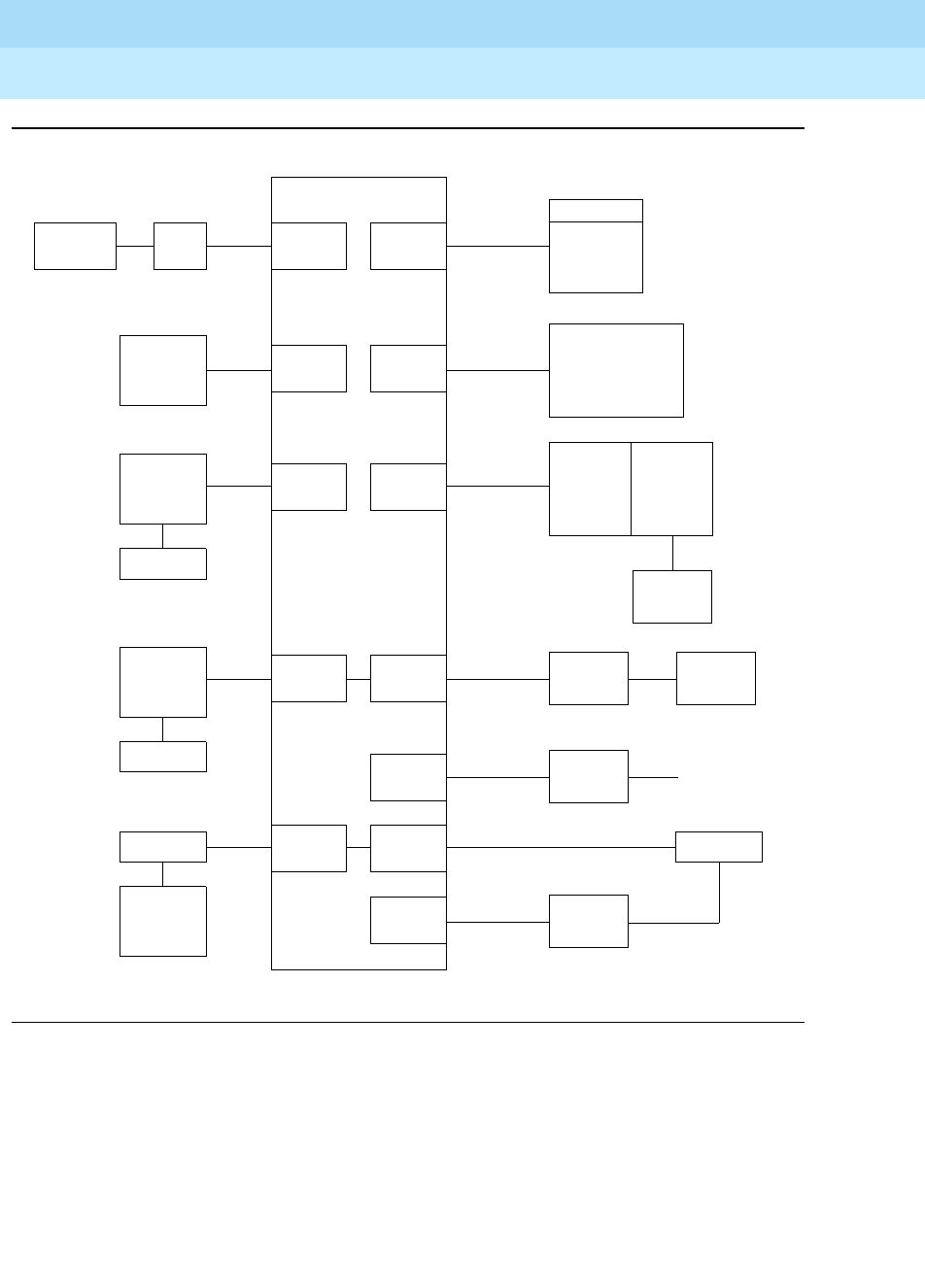
Figure 1-1 shows a typical arrangement of terminals and adjuncts connected to
the system switch.
DEFINITYEnterpriseCommunicationsServerandSystem75andSystem85
Terminals and Adjuncts Reference
555-015-201 Issue 11
December 1999
Introduction
1-3The Purpose of This Manual
1
Figure 1-1. Interface Between System Switch and Typical Terminals/Adjuncts
Data Data
Module
Data Data
Module
To Private
Data
Voice/DataVoice
Data
Terminal Data
Unit EIA
Port
Data Data Digital
Port
Digital Switch
Voice
Adjunct
Digital
Voice
Terminal
Voice/DataVoice
Analog
Voice
Terminal
Hybrid
Voice
Terminal
Display/
Keyboard
Data Terminal
with Voice
Digital
Voice
Terminal
Data
Module
Adjunct
Analog
Port Digital
Port
Hybrid
Port Digital
Port
Data
Data
Terminal
DataVoice
Digital
Voice
Terminal
Adjunct
Digital
Port Digital
Port Data
Module Data
Terminal
Data
Digital
Port Line Trunk
Facilities
Analog Data
Voice/
Terminal
DCP
PC/PBX Digital
Port Analog
Port Modem
Data
Digital
Port
RS-232
Data

DEFINITYEnterpriseCommunicationsServerandSystem75andSystem85
Terminals and Adjuncts Reference
555-015-201 Issue 11
December 1999
Introduction
1-4The Organization of This Manual
1
The Organization of This Manual
The remainder of this manual is divided into nine main sections; tabs are provided
for convenient access to each section. All equipment descriptions are supported
by illustrations.
General Information — Gives background data that applies to the entire range of
equipment covered in this manual.
Exposed Port Protection — Contains information on the protection required by
exposed ports. This section also lists some of the Lucent Technologies protection
devices and gives parameters that non-Lucent Technologies devices must meet.
Adjunct Power — Lists the different terminals and adjuncts that require adjunct
power supplies and the recommended adjunct power supply. Information has also
been provided about the MSP-1 local power supply and, more recently, about the
1151A1 and the 1151A2 with Battery Holdover which has replaced the MSP-1.
Administration — When some of the newer terminals are used with some older
versions of the switches, the administration of the switch does not allow for the
use of the new terminals. These new terminals must be administered using the
administration procedures of a similar older terminal. This is called aliasing. This
section contains the aliasing information and the appropriate caveats.
Voice Terminals — Provides detailed coverage of the main groups of voice
terminals, divided into 13 tabbed subsections. This section contains detailed
information on each voice terminal that can be ordered as a component of a
DEFINITY switch, System 75, or System 85. It also contains brief descriptions of
voice terminals that were previously installed in earlier business communications
systems. Before you install the voice terminal or telephone, check each
description to see if these voice terminals are compatible with a DEFINITY G1,
G2, or G3, a DEFINITY ECS, System 75, or System 85.

DEFINITYEnterpriseCommunicationsServerandSystem75andSystem85
Terminals and Adjuncts Reference
555-015-201 Issue 11
December 1999
Introduction
1-5The Organization of This Manual
1
The 13 tabbed subsections and the voice terminals described in each subsection
are listed as follows:
6400 SERIES
Models 6402 and 6402D
Models 6408+ and 6408D+
Models 6416D+ and 6416D+M
Models 6424D+ and 6424D+M
7100 SERIES
Model 7101A
Models 7102A and 7102 Plus
Models 7103A Fixed Feature and
7103A Programmable
Model 7104A
7200 SERIES
Model 7203H
Model 7205H
7300 SERIES
Model 7303S
Model 7305S
7400 SERIES
Model 7401D
Model 7401 Plus
Model 7402 Plus
Model 7403D
Model 7404D
Model 7405D
Model 7406D
Model 7406 BIS
Model 7406 Plus
Model 7407D
Model Enhanced 7407D
Model 7407 Plus
Model 7410D
Model 7410 Plus
Model 7434D
Model 7444
8400 SERIES
Model 8403
Model 8405
Model 8410
Model 8411
Model 8434 and 8434DX
CALLMASTER
602 CALLMASTER
CALLMASTER II
CALLMASTER III
CALLMASTER IV
CALLMASTER V
CALLMASTER VI
500/2500 SERIES
Model 500 Series
Model 2500 Series
Model 2500 DMGC
Model 2500 YMGK
Models 2500 MMGL and 2500 MMGM
Models 2500 YMGL and 2500 YMGM
Models 2500 YMGN and 2500 YMGP
6200 SERIES
Model 6210
Models 6218 and 6220
8100 SERIES
Models 8101 and 8102M
Models 8102 and 8102M
Models 8110 and 8110M
ISDN VOICE TERMINALS
Model 7505 ISDN
Model 7506 ISDN
Model 7507 ISDN
Model 8503T ISDN
Model 8510T ISDN
Model 8520T ISDN
CORDLESS/WIRELESS TELEPHONES
MDC 9000 Cordless Telephone
MDW 9000 Wireless Telephone
MDW 9031DCP Wireless Pocket Phone
OTHER
Voice terminals reusable
from other systems:
Models 7203H, 7303H,
7305H01B, and 7305H02B
Multi-Button Electronic
Telephone (MET) Sets

DEFINITYEnterpriseCommunicationsServerandSystem75andSystem85
Terminals and Adjuncts Reference
555-015-201 Issue 11
December 1999
Introduction
1-6The Organization of This Manual
1
Adjuncts — Contains information on the devices that can be used with voice
terminals to supplement services and features. This section contains information
on the controls, buttons, lights, and functions of a DEFINITY G1, G2, and G3, a
DEFINITY ECS, System 75, or System 85 voice terminals and telephone
adjuncts. Adjuncts that are identical in appearance and function, but have different
codes, are covered under the same heading. Adjuncts that are basically data
modules are covered in the Data Modules section in this manual.
The adjuncts covered in this section are:
Call Coverage Modules Message Waiting Indicator
Digital Display Module Speakerphones
Function Key Module Loudspeaker
Expansion Modules Messaging Cartridge
Tip/Ring Interface Module Automatic Dialer
Headset Adapters
Data Modules — Contains information on the devices that provide data
communications interface. This section contains information on the data modules
and other related data equipment used with a DEFINITY G1, G2, and G3, a
DEFINITY ECS, System 75, or System 85. These devices provide data interface
functions which include modems, protocol converters, and data units.
The data modules covered in this section are:
–7400A Data Module –Modular Processor Data
–7400B and 7400B Plus Module (MPDM)
Data Module –Modular Trunk Data
–7400D Data Module Module (MTDM)
–7500B Data Module –3270 Data Module
–8400B Plus Data Module –Asynchronous Data Unit (ADU)
–ISDN Asynchronous Data –Multiple Asynchronous Data
Module (ADM) Unit (MADU)
–Digital Terminal Data –DCIU Interface Units
Module (DTDM) –2500-SERIES Data Service Unit
–Z702AL1 Data Service Unit –Modems (Data Sets)
–703A Data Service Unit –Local Distribution Service
–DEFINITY High Speed Link (HSL) Unit (LDSU)
–Processor Data Module (PDM) –Isolating Data Interface (DI)
–Trunk Data Module (TDM) –Protocol Converters
PC Platforms (PC/PBX and PC/ISDN) and Application Software — Contains
information on the different PC/PBX Platforms, the PC/PBX Connection, and
E78 Plus®/ISDN.
Blank Templates for Model Design — Includes blank templates of voice
terminal faceplates on which the Software Associate can designate the numbers,
feature codes, or features to be administered on each voice terminal button.

General Information
2-1Voice Terminals
2
DEFINITYEnterpriseCommunicationsServerandSystem75andSystem85
Terminals and Adjuncts Reference
555-015-201 Issue 11
December 1999
2
General Information
This section provides general information on all of the equipment described in this
manual. Information is provided on voice terminals, adjuncts, data modules, and
data terminals. Detailed information on these types of equipment can be found
behind the tab for each particular type of equipment.
Voice Terminals
The advanced, multi-appearance voice terminals combine the capabilities of both
a telephone and a terminal and have a variety of controlling and monitoring
functions. While providing basic telephone service (placing and answering calls),
voice terminals can also be used to activate the advanced features of the system.
This part explains higher level topics that apply to voice terminals as a group and
contains descriptions of facilities and characteristics that are common to all or
most terminals. Table 2-1 presents a summary of all voice terminals used with a
DEFINITY G1, G2, and G3, a DEFINITY ECS, System 75, and System 85.
The complete line of voice terminals are two basic types,
single-line voice
terminals
and
multi-appearance voice terminals.
The operational differences
between these types are in the way they access features and the way they receive
calls.

DEFINITYEnterpriseCommunicationsServerandSystem75andSystem85
Terminals and Adjuncts Reference
555-015-201 Issue 11
December 1999
General Information
2-2Voice Terminals
2
Single-Line Voice Terminals
The term “single-line” means that only one incoming call can be ringing at an idle
terminal. Once an incoming call has been answered, however, a single-line voice
terminal can handle both the active call and another call on hold or waiting. When
a single-line terminal user is busy on a call, an incoming call does not ring but
alerts the user via a “call waiting tone” (in the handset or speakerphone) that a call
is waiting to be answered. While a single-line terminal is occupied with two calls,
any other calls placed to the terminal get a busy tone.
All single-line voice terminals are analog in operation; that is, transmission of all
signals between the terminal and its port, at the system digital switch, is in analog
form over a tip and ring pair of wires. The port circuit provides analog/digital signal
conversion. Power for these terminals is supplied from the switch on the single
voice pair. Single-line terminals have many applications but are more limited in
their access to system features than multi-appearance terminals.
Multi-Appearance Voice Terminals
A multi-appearance voice terminal gives its user much more flexibility in handling
calls than a single-line voice terminal. A multi-appearance voice terminal,
represented by a unique primary extension number, has multiple call appearances
(buttons with lights) where incoming calls to the number can be answered and
outgoing calls can be originated. Incoming calls can ring simultaneously at all
appearances except for those translated as originate-only. As long as at least one
appearance is idle, callers will not receive busy tone. When all call appearances,
except call appearances translated as originate-only, are busy, callers will hear
busy tone unless the incoming call is a priority call or the Restrict Last
Appearance feature is deactivated. The terminal user must decide the order to
answer multiple incoming calls.
The two sub-types of multi-appearance voice terminals are digital and hybrid.
Digital terminals generate and receive voice and control signals in digital form.
Connection between terminals and the system switch is over 2-pair digital links;
no conversion is necessary at the digital line port. Hybrid terminals, as the name
implies, combine analog and digital. They are connected to the system switch by
three pairs of links; on MET*-like hybrid sets, one pair is for analog voice, and the
other two pairs are for digital control signals, and on ATL†-like hybrid sets, one pair
is for digital control signals, and the other two pairs are for analog voice. DC power
for all multi-appearance terminals (except for the 7404D and 7407D01B, which
are AC powered) is conducted from the switch over the digital pairs.
Digital multi-appearance voice terminals have several important advantages over
hybrids:
* The Multi-Button Electronic Telephone (MET) sets are described in Chapter 19, “Other
Voice Terminals.”
† Analog Terminal Loop (ATL) protocol is used predominantly in MERLIN telephone sets.

DEFINITYEnterpriseCommunicationsServerandSystem75andSystem85
Terminals and Adjuncts Reference
555-015-201 Issue 11
December 1999
General Information
2-3Voice Terminals
2
■Digital voice terminals can support and control data terminals.
■The Digital Communications Protocol (DCP) or ISDN-BRI interface
between a digital voice terminal and the system switch supports
simultaneous voice and data calls over the terminal’s standard mounting
cord.
■Digital terminals have a wider selection of adjuncts.
■Call information displays are available with some digital voice terminals.

DEFINITYEnterpriseCommunicationsServerandSystem75andSystem85
Terminals and Adjuncts Reference
555-015-201 Issue 11
December 1999
General Information
2-4Voice Terminals
2
Table 2-1. Voice Terminals Usable with DEFINITY, System 75,
and System 85
Type Model
Single-Line Analog 2500 Series
2500 DMGC
2500 YMGK/2500 YMGL/2500 YMGM
2500 MMGL/2500 MMGM, 2500 MMGN/2500 YMGP
6210, 6218, 6220
7101A
7102A, 7102 Plus
7103A Fixed Feature and 7103A Programmable
7104A (usable only with DEFINITY G1 and System 75)
8101, 8101M, 8102, 8102M, 8110, and 8110M
Multi-Appearance Hybrid 7203H (usable only with DEFINITY G2 and System 85)
7205H (usable only with DEFINITY G2 and System 85)
7303S
7305S
Single-Appearance Digital 6402 and 6402D
7401D and 7401 Plus
These four models (have two virtual*appearances,
but no call appearance buttons)
Multi-Appearance Digital 6408, 6408+, 6408D, 6408D+, 6416D+, 6416D+M, 6424D+, and 6424D+M
7402 Plus
7403D, 7404D, 7405D
7406D, 7406BIS, 7406 Plus
7407D, Enhanced 7407D, 7407 Plus
7410D, 7410 Plus
7434D
7444
8403, 8405, 8410, 8411, 8434, and 8434DX
602A, 602D CALLMASTER
CALLMASTER II with Recorder Interface
CALLMASTER III without Recorder Interface
CALLMASTER IV
CALLMASTER V
CALLMASTER VI
ISDN Terminals 7505, 7506, 7507 (usable only with DEFINITY)
8503T, 8510T, 8520T (usable only with DEFINITY G2 and G3)
Cordless and Wireless MDC 9000 Cordless Telephone
MDW 9000 Wireless Telephone
Continued on Next Page
REUSABLE FROM EARLIER SYSTEMS

DEFINITYEnterpriseCommunicationsServerandSystem75andSystem85
Terminals and Adjuncts Reference
555-015-201 Issue 11
December 1999
General Information
2-5Voice Terminals
2
Facilities Common to All Voice Terminals
Every DEFINITY G1, G2, and G3, DEFINITY ECS, System 75, and System 85
voice terminal has the following equipment:
■A pushbutton pad for touch-tone dialing (except for the Model 500, which
has a rotary dial).
■A handset with a coiled modular cord.
■A 7-foot modular mounting cord (except for the Model 2554 wall set).
Buttons
All multi-appearance voice terminals and most single-line terminals have buttons
for handling calls and activating various functions that enhance basic calling.
Fixed Feature Buttons
Buttons that are factory labeled and require no administration are referred to as
fixed feature buttons. The following buttons, in several combinations, are found on
most voice terminals. They are dedicated to standard calling functions and are
located adjacent to or above the pushbutton dial pad for calling convenience.
NOTE:
Fixed feature buttons that are limited to a small number of terminals are
explained in the detailed descriptions of those terminals.
■Recall Button (on older sets)—provides a timed flash that is more accurate
than a manual switchhook flash and prevents accidental dropping of calls.
The following list of uses for this button is only valid for single-line
terminals:
Type Model
Single-Line Analog 500 (can also be ordered new)
2500 Series (can also be ordered new)
Multi-Appearance Hybrid
(MERLIN)7305H, 7305H01B, and 7305H02B
Multi-Button Electronic
Telephone (MET) Sets
10 Button with or without Built-In Speakerphone, 20 Button, 30 Button
7203M (12 button)
* The word “virtual” refers to the fact that there are no call appearance buttons associated with either appearance. Refer
to the description of the 7401D and 7401 Plus Voice Terminal for more information.
Table 2-1. Voice Terminals Usable with DEFINITY, System 75,
and System 85 — Continued

DEFINITYEnterpriseCommunicationsServerandSystem75andSystem85
Terminals and Adjuncts Reference
555-015-201 Issue 11
December 1999
General Information
2-6Voice Terminals
2
— Put an active call on hold and obtain recall dial tone for making
another call.
— Disconnect from a second call and return to a call on hold, when
pressed twice.
— Place an active call on hold and answer a waiting call using Dial
Access Code, then toggle between the two calls (using the Recall
button and Dial Access Code).
— Place an active call on hold; receive recall dial tone, and dial the
Feature Access Code to answer a waiting call. Toggle between the
two calls by performing the same action.
— Add a party, previously put on hold, to a conference with a third
party.
— Drop the party previously added.
■Disconnect Button (on older sets)—allows the terminal user, after
completing one call, to permanently disconnect from the call and get dial
tone for placing a new call without going on- and off-hook. On System 85
and DEFINITY G2, depending on the administration, this button can be
used to reconnect to the call on hold on multiple appearance voice
terminals.
■Hold Button—is used to temporarily disconnect from one call, without
dropping it, so that another call can be answered or originated. The user
can return to the call on hold.
■Drop Button—is used to permanently disconnect the last party added to a
conference call. On System 85 and DEFINITY G2, this button also gives
dial tone on the same call appearance if dialing or on a 2-party call.
NOTE:
Onsomevoiceterminals,thisbuttonisalsousedtoperformatestof
the voice terminal’s lights, ringer, and display (if the terminal has
one).
■Conference Button—enables the terminal user to set up a conference call
by adding new calls to an existing 2-party connection. The user can add as
many as five calls to a conference. (On System 85 and DEFINITY G2 the
user can only build a 3-party conference call using this button; 6-party
conference calls can be built by the attendant.)
NOTE:
On some voice terminals, this button is also used to select a
personalized ring from eight available ringing patterns.
■Transfer Button—enables the terminal user to shift an active call to
another voice terminal.
■Select Ring Button (on older sets)—enables the terminal user to select a
personalized ringing pattern.

DEFINITYEnterpriseCommunicationsServerandSystem75andSystem85
Terminals and Adjuncts Reference
555-015-201 Issue 11
December 1999
General Information
2-7Voice Terminals
2
■Speaker Button—turns on either a listen-only speaker or a 2-way
speakerphone which allows the user to speak and listen to the far-end
party.
NOTE:
On some voice terminals, this button also allows the user to initiate
an acoustic test of the surrounding environment (the Reset
Speakerphone feature) through a series of tones. When the tones
stop, the speakerphone has finished adjusting itself for optimal
performance.
■Mute Button—turns off the microphone of the built-in speakerphone or the
handset so the other person on the call cannot hear you.
Administrable Buttons
Buttons that are not fixed feature buttons are administered (or assigned) by the
System Manager or the terminal user for many functions. Buttons that may be
administered include call appearance/feature buttons and feature-only buttons.
Every multi-appearance voice terminal has a minimum of three buttons while
others have as many as 34 buttons that can be administered as call appearances,
that is, positions for answering incoming calls and originating outgoing calls (see
Figure 2-1). In DEFINITY G1, G3, and System 75, software defaults the first three
of these buttons for appearances of the terminal’s primary (or home) extension
number; the System Manager has the option of administering Button #3
differently. In DEFINITY G2 and System 85, no buttons are defaulted for the
primary extension number; the System Manager
must
administer all the required
positions. Buttons not used for the primary extension number can be assigned as
appearances of other extensions or for activating optional features.
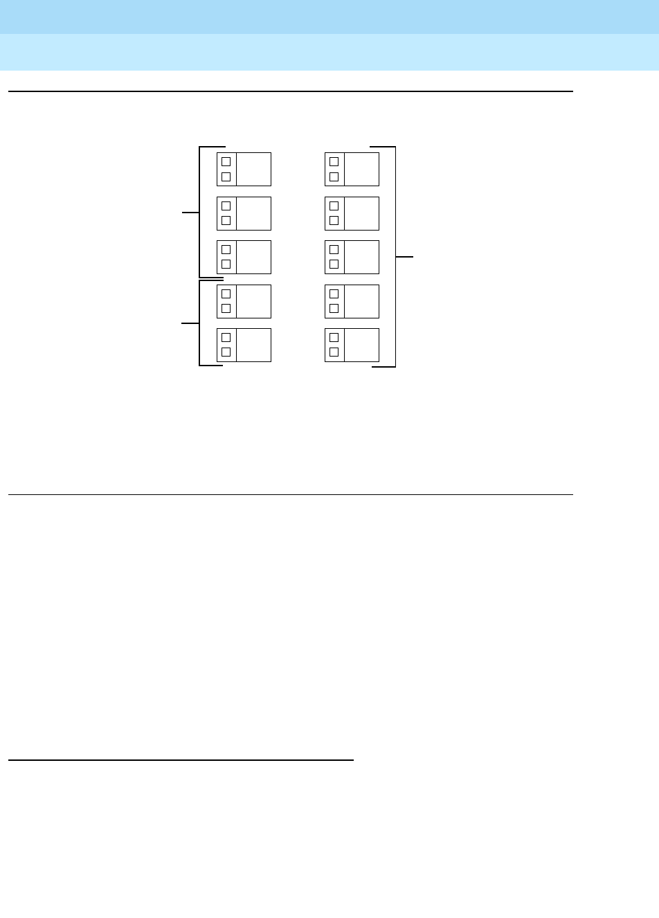
DEFINITYEnterpriseCommunicationsServerandSystem75andSystem85
Terminals and Adjuncts Reference
555-015-201 Issue 11
December 1999
General Information
2-8Voice Terminals
2
Figure 2-1. Call Appearance/Feature Buttons
Associated with each call appearance/feature button is a pair of lights that provide
information on the availability and status of the appearance. These lights are
described in the next part of this manual (titled “Lights”).
Any button that can be administered and is not used for a call appearance can be
assigned to an optional feature. Included in this category are buttons with two
lights (call appearance/feature buttons) and buttons with one or no lights, intended
specifically for features. Some features require light feedback to inform the
terminal user when the feature is active; others are simple, one-time operations
for which light feedback would be meaningless. Good feature administration
matches features to appropriate buttons whenever possible.
Lights
Indicator lights provide silent visual reminders to the voice terminal user regarding
lines, features, and messages taken at other locations. The lights on voice
terminals connected to a DEFINITY G1, G2, and G3, a DEFINITY ECS,
System 75, or System 85 are light-emitting diodes (LEDs) or neon lights.
On all multi-appearance voice terminals, each call appearance/feature button has
two indicator lights: a red light and a green status light. When a call
appearance/feature button is used for a feature, only the status light is
1
Usually
2
3
4
5
Administered as
Call Appearances
of Terminal’s Primary
Extension Number
Administrable
as Call Appearances
or Features
Call Appearance/Feature Buttons
6
7
8
9
10
Administrable as
Call Appearances
or Features
NOTE: Example shows button field of
7410 Plus voice terminal.
Other terminals may have different
arrangements, but Buttons 1, 2,
and 3 are always present.
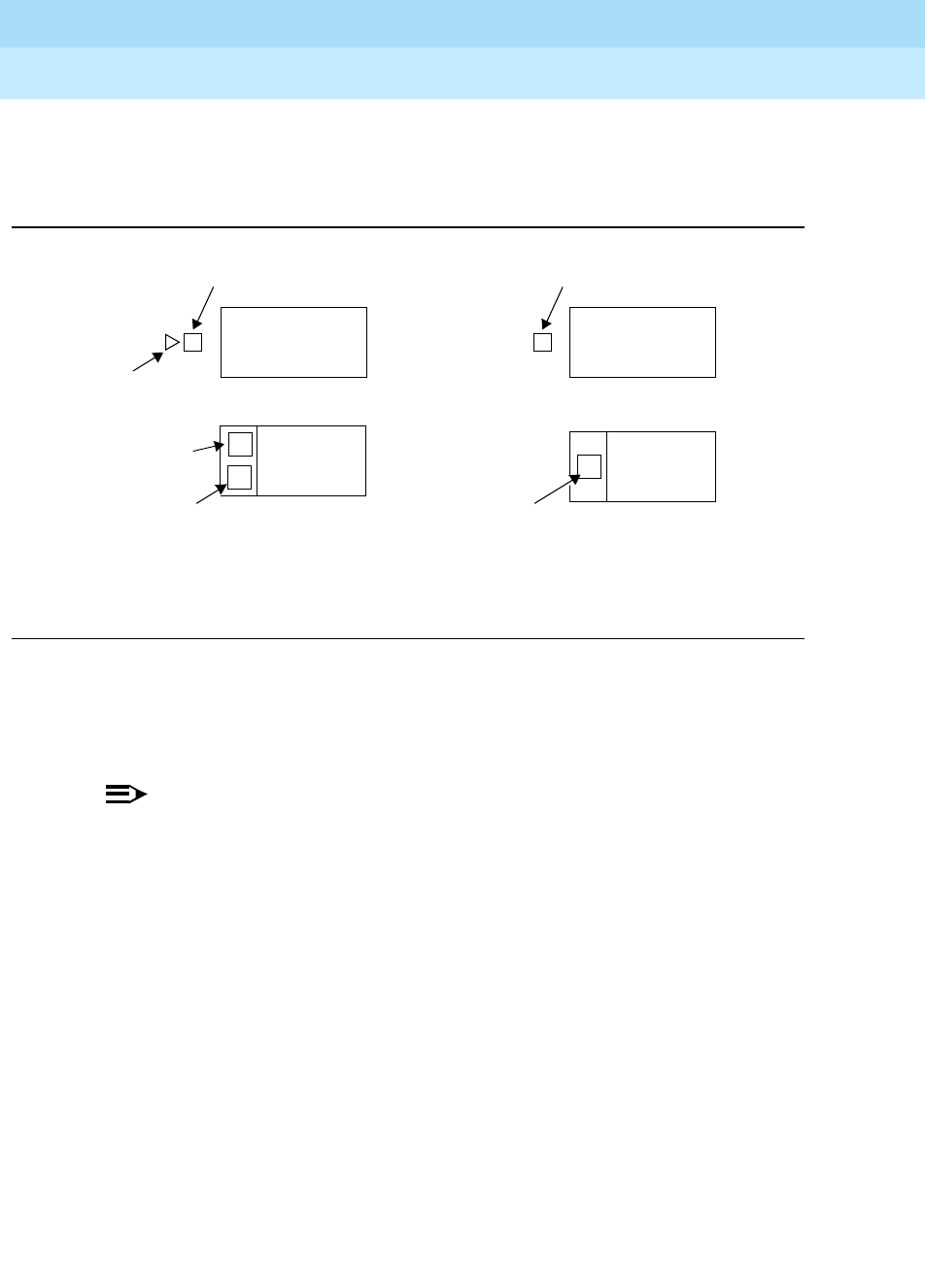
DEFINITYEnterpriseCommunicationsServerandSystem75andSystem85
Terminals and Adjuncts Reference
555-015-201 Issue 11
December 1999
General Information
2-9Voice Terminals
2
operational; the red light remains off at all times. Feature-only buttons have either
a single green status light or no light at all. The various arrangements of red and
green lights are shown in Figure 2-2.
Figure 2-2. Button Lights
Red Light
The red light normally has two states: lighted steadily or dark (off).
NOTE:
On the ISDN-BRI 7505, 7506, and 7507 sets, the red light flashes when the
set is using phantom power.
One red light is always on at a multi-appearance voice terminal when the handset
is on hook. It identifies the call appearance the user will be automatically
connected to if the handset is lifted. When the handset is lifted, the red light
identifies the call appearance that is active.
The red light is off when the handset is lifted but not connected to a call
appearance. For example, when one call has been put on hold but another call
appearance button has not been pressed. When certain features such as
Preselection, Idle Line Originating preference, or No Line Originating Preference
are administered, the red light is also off while on hook.
Green Status Light
The green status light can indicate any one of the following six conditions:
■Off—the call appearance is idle or the assigned feature is not activated.
Red Light
Green Status Light Green Status Light
Green Status Light
Red Light
Two Styles of Light Arrangement for
Call Appearance/Feature Buttons
Green Status Light
Two Styles of Light Arrangement for
Feature-Only Buttons

DEFINITYEnterpriseCommunicationsServerandSystem75andSystem85
Terminals and Adjuncts Reference
555-015-201 Issue 11
December 1999
General Information
2-10Voice Terminals
2
■Lighted steadily—the call appearance is busy or the assigned feature is
active.
■Flashing (slow on-off for equal periods, one cycle per second)—an
unanswered incoming call on that call appearance.
■Fluttering (fast on-off for equal periods, 10 cycles per second)—a call
placed on hold on that call appearance by the voice terminal user.
■Broken Fluttering (fast on-off modulated at the slow rate)—feature denial to
the calling voice terminal or an unknown or invalid action.
■Winking (long on-short off at about three cycles per second)—a call placed
on hold from another voice terminal or an action pending.
Message Light
The Message light, when on, indicates that a message is waiting for the voice
terminal’s user (for example, Leave Word Calling or voice mail messages). When
the user retrieves the message, the light is automatically turned off.
Tones
The tones that a voice terminal user hears can be divided into two categories:
■Ringing Tones—those that are generated in the base of the voice terminal
and can be heard in the surrounding area; they indicate incoming calls.
■Handset Tones—those that are transmitted through the handset and heard
only by the user or through the speakerphone when it is turned on.
External Ringing Tones
Ringing tones are the only tones heard
outside the voice terminal
when it is
receiving a call. This signal cycles in 1-, 2-, or 3-ring patterns. On System 75 and
DEFINITY G1 and G3, only one cycle of ringing is heard if the multi-appearance
voice terminal is busy with another call. On System 85 and DEFINITY G2, the
cycling repeats (except on the ISDN 7500-series sets).
■One ring—a call from another voice terminal in the system
■Two rings—a call from the attendant or outside caller
■Three rings—priority calls, for example, Automatic Callback, Priority
Calling, or Ringback from a queued call
■One short unmodulated tone—an intercom call
■Ring-Ping (half ring)—a call redirected away from the voice terminal
because Send All Calls or Call Forwarding is active; also called coverage
tone.
■On System 85 and DEFINITY G2, any of these external tones, plus a
repeated unmodulated tone, may be administered to indicate an intercom
call.

DEFINITYEnterpriseCommunicationsServerandSystem75andSystem85
Terminals and Adjuncts Reference
555-015-201 Issue 11
December 1999
General Information
2-11Voice Terminals
2
Handset Tones
The following tones are heard through the handset:
■Answer Tone—a high-pitched continuous tone indicating that a data
endpoint has answered.
■Busy Tone—a low-pitched tone repeated 60 times a minute; indicates that
the number dialed is in use.
■Call Waiting Tone (Single-Line Voice Terminals)—one, two, or three
beeps (short bursts of high-pitched tone), not repeated; indicates to the
user at a busy single-line terminal that an incoming call is waiting to be
answered. The number of beeps indicates the source of the waiting call:
— One beep—a call from another voice terminal in the system
— Two fast beeps—a call from the attendant or an outside caller
— Three fast beeps—a priority call
■Confirmation Tone—(three short bursts of tone) indicates that a feature
activation or cancellation has been accepted, or that an outgoing call from
a single-line voice terminal has been placed in a ringback queue.
■Coverage Tone—(one long burst of tone) indicates to the calling party that
a call to an extension number will be answered at another extension
number by a covering user.
■Dial Tone—(a continuous steady tone) indicates that dialing or feature
activation can begin.
■Intercept Tone—(an alternating high and low tone) indicates either a
dialing error or a denial of the service requested.
■Recall Dial Tone—(three short bursts of dial tone followed by steady dial
tone) indicates that the feature requested has been accepted and dialing
can start.
■Recorded Telephone Dictation Ready Tone—(a high-pitched continuous
tone) indicates that a dictation machine has been connected to the voice
terminal.
■Reorder Tone—(a fast-busy tone repeated 120 times a minute) indicates
that all outgoing trunks are busy or feature resource is not available. Try
again.
■Ringback Tone—(a low-pitched tone repeated 15 times a minute)
indicates to the calling party that the number dialed has been reached
successfully and is ringing.
■Ringback Tone, Call Waiting—(a ringback tone with a short lower-pitched
signal at the end) indicates to the calling party that the extension called is
busy, but that the called party has been given the call waiting signal.
■Time-Out Tone— (an alternating high and low tone [same as intercept
tone]) indicates a failure to dial within a preset interval (usually 10 seconds)
after lifting the handset or after dialing the previous digit.

DEFINITYEnterpriseCommunicationsServerandSystem75andSystem85
Terminals and Adjuncts Reference
555-015-201 Issue 11
December 1999
General Information
2-12Adjuncts
2
■Warning Tone (Bridging)—(a low-pitched tone heard by all parties in a
Busy Verification attempt that bridges on to an active call) initially applied in
a 2-second (System 75 and G1) or 4-second (System 85 and G2) burst,
then in half-second bursts every 15 seconds.
Desk/Wall Mounting Arrangements
All the voice terminals covered in this manual, except the Model 2554, are
intended for free-standing desktop use. However, wall-mounting is feasible for
many terminals and appropriate kits are available. The detailed description of
each voice terminal contains wall-mounting information and limitations.
Adjuncts
Adjuncts are optional devices that extend the existing capabilities of voice
terminals or provide new services. Some adjuncts are physically attached to their
voice terminals, and others are free-standing, connected by way of mounting
cords. The adjuncts have styling and colors that are compatible with the
associated voice terminals.
Table 2-2 provides a cross-reference between adjuncts and the voice terminals
with which they are used. The following limitations apply to the use of multiple
adjuncts:
■A speakerphone and a headset adapter cannot be connected to the same
voice terminal simultaneously because they plug into the same jack on the
terminal.
■A C401A Call Coverage Module and a D401A Digital Display Module
cannot be mounted on the same 7405D or 7434D Voice Terminal
simultaneously because they attach to the same part of the terminal.
None of the adjuncts have facilities for wall mounting, and wall-mounting kits are
not available. However, the modules (call coverage, function key, and digital
display) are attached to their voice terminals, which can then be mounted on a
wall. Free-standing adjuncts (speakerphones and headset adapters) associated
with wall-mounted terminals can be placed on a nearby shelf or table.
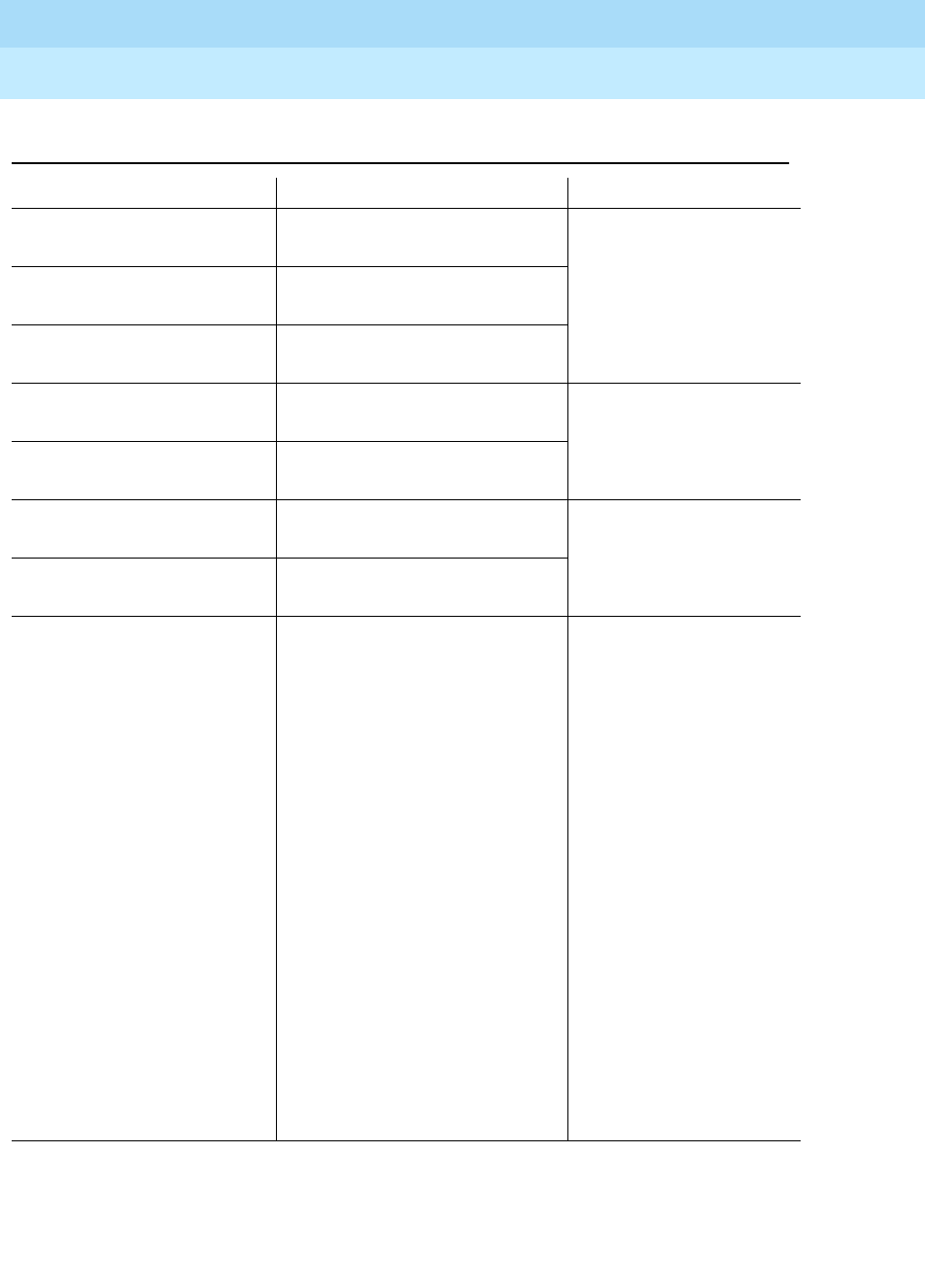
DEFINITYEnterpriseCommunicationsServerandSystem75andSystem85
Terminals and Adjuncts Reference
555-015-201 Issue 11
December 1999
General Information
2-13Adjuncts
2
Table 2-2. Adjunct/Voice Terminal Compatibility
Adjunct Terminals Function
Call Coverage Module,
C201A 7205H Adds 20 call
appearance/ feature
buttons
Call Coverage Module,
C401A 7405D
7434D
Call Coverage Module,
C401B 7405D
7434D
Digital Display Module,
D401A 7405D
7434D Displays call-related
and personal service
information
Digital Display Module,
D401B 7405D
7434D
Function Key Module,
F201A 7205H
Adds 24 feature buttons
Function Key Module,
F401A 7405D
Headset Adapter, 500A 6402, 6402D, 6408, 6408+,
6408D, 6408D+, 6416D+,
6424D+
7102 Plus
7103A
7203H
7205H
7401 Plus
7402 Plus
7403D
7405D
7406D
7406BIS
7406 Plus
Enhanced 7407D
7407 Plus
Provides for connection
and control of standard
headset
Continued on Next Page

DEFINITYEnterpriseCommunicationsServerandSystem75andSystem85
Terminals and Adjuncts Reference
555-015-201 Issue 11
December 1999
General Information
2-14Adjuncts
2
Headset Adapter, 500A
(continued) 7410D
7410 Plus
7434D
7444
8403, 8405,
8410, 8411, 8434/8434DX
CALLMASTER
8102
7505,06,07 ISDN
8503T ISDN
8510T ISDN
8520T ISDN
515 BCT
Headset Adapter, 502A 7303S
7305S
Provides for connection
and control of standard
headset
Message Waiting Indicator,
Z34A 2500 Indicates that a
message has been left
for the terminal
Messaging Cartridge 7404D Provides display of
call-related and
personal service
information on data
terminal screen
PC/PBX Plug-in Cartridge 7404D Provides interface with
PCs
Speakerphone, S101A
Speakerphone, S201A
Same as 500A
Headset Adapter
Provides hands-free
calling
Continued on Next Page
Table 2-2. Adjunct/Voice Terminal Compatibility — Continued
Adjunct Terminals Function

DEFINITYEnterpriseCommunicationsServerandSystem75andSystem85
Terminals and Adjuncts Reference
555-015-201 Issue 11
December 1999
General Information
2-15Data Modules
2
Several power supplies and connection schemes are available for providing
auxiliary adjunct power when it is required. Refer to the Adjunct Power section
later in this manual for more information on these power sources.
Data Modules
Data modules provide an interface between the system’s digital switch and Data
Terminal Equipment (DTE) or Data Communications Equipment (DCE). DTE is
defined as a data source or a data link or a combination of both; typical examples
are data terminals and host computers. DCE is equipment that provides the
functions for establishing, maintaining, and terminating a data call; a modem is an
example of DCE.
An interface device between the switch and DTE or DCE is necessary because
the set of data transmission rules and formats—the data protocol—at the switch is
different from the protocol at the DTE or DCE. The digital ports of the switch
present a DCP or ISDN-BRI interface to all devices connected to them. DCP
supports simultaneous voice and data communications by multiplexing the two
sets of signals into one digital stream. Digital voice terminals and some data
terminals can be connected directly to the switch. But, if a data endpoint has a
different protocol (EIA RS-232C or RS-232D is the most common) than the
Speakerphone, S102A
Speakerphone, S202A
Same as 502A
Headset Adapter
Provides hands-free
calling
Provides improved
voice quality by
adapting to room
acoustics
Speakerphone, 4A
Speakerphone, 203A
Loudspeaker, 107
2500
Analog or
stand-alone 2500
Provides hands-free
calling
Provides hands-free
answering. Provides
hands-free calling when
not used as
stand-alone.
Provides amplification
for the received voice
signal
Automatic Dialer, 2870A1 MET Provides the capability
to record and
automatically dial 31
numbers
Table 2-2. Adjunct/Voice Terminal Compatibility — Continued
Adjunct Terminals Function
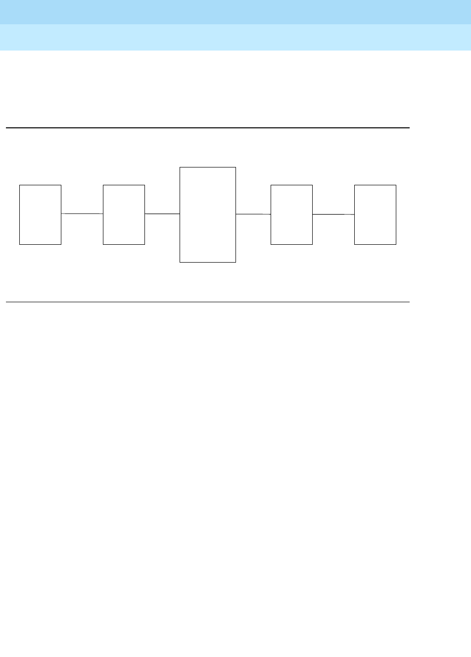
DEFINITYEnterpriseCommunicationsServerandSystem75andSystem85
Terminals and Adjuncts Reference
555-015-201 Issue 11
December 1999
General Information
2-16Data Modules
2
switch, a data module must be inserted to provide compatibility. The data module
provides the two-way data signal conversion and processing required between
different protocols. Figure 2-3 shows a simplified diagram of the components of a
typical data link.
Figure 2-3. Data Link Components
The connection between a data module and a data endpoint must always have a
DCE or DTE interface. If the endpoint is a DCE, the data module must present a
DTE interface to it. If the endpoint is a DTE, then the data module must present a
DCE interface. In general, modules are classified as DCE- or DTE-type according
to the kind of data endpoint to which they are connected.
Data modules are available to match a wide variety of data needs:
■Asynchronous operation at data rates from 0.3-19.2 kbps and even, odd,
mark/space, zero/one or no parity options.
■Synchronous operation at data rates of 0.3, 1.2, 2.4, 4.8, 9.6, 19.2, 56, and
64 kbps.
■Half- or full-duplex operation and internal or external timing options at the
appropriate data rates.
The following data equipment is available with a DEFINITY G1, G2, and G3, a
DEFINITY ECS, System 75, and System 85:
■7400A Data Module — In DTE mode, works with asynchronous DCE in
the modem pool at data rates of 0.3-19.2 kbps, full-duplex. Supports both
Hayes-compatible and D-lead modems. In DCE mode, the 7400A has
Hayes®, Keyboard Dial or Answer-Only interface. Also works with
asynchronous DTE where rack mounting is needed. Takes the place of
MTDM or MPDM in asynchronous applications.
■7400B and 7400B Plus Data Modules — Works with asynchronous DTE
at data rates of 0.3-19.2 kbps, full-duplex. Can be used with most
7400-series DCP voice terminals for simultaneous voice/data or
Data
Endpoint Data
Module
Data
Module
Data
Endpoint
DEFINITY
G1, G2, G3
System 75
or
System 85
Digital
Switch
RS-232C/D
V.3 5
RS-449
DCP RS-232C/D
V.35
RS-449
DCP

DEFINITYEnterpriseCommunicationsServerandSystem75andSystem85
Terminals and Adjuncts Reference
555-015-201 Issue 11
December 1999
General Information
2-17Data Modules
2
stand-alone. Emulates a Hayes-compatible modem, therefore, can be used
with standard PC communications packages. Takes the place of previous
DCP asynchronous data stands.
■7400D Data Module — Works as a DCE device between a DTE and the
PBX. A DTE configuration (that is, modem pooling) is not supported, and
the DCE configuration is limited to an Answer-Only-type interface option.
Dates rates range from 0.3 to 19.2 kbps.
■8400B Plus — Works as a data service link between a DTE device, a
2-wire voice terminal such as the 8400-Series voice terminals, and a
DEFINITY G3V2 or later. At the desk, the 8400B Plus data module
provides asynchronous communication speeds ranging from 0.3 to
19.2 kbps.
■Modular Processor Data Module (MPDM) — Works with synchronous
DTE at data rates of 0.3-64 kbps. Also works at full- or half-duplex with
internal or external timing at the appropriate data rates. Supports V.35,
RS-232, and RS-449 interfaces and RS-366 Automatic Calling Unit
interface at the previously mentioned rates. Video codes are an example of
56 or 64 kbps endpoints where calls are set up via the RS-366 interface.
The MPDM also supports asynchronous applications, but the 7400B Plus
supersedes it for applications requiring Hayes emulation and the 7400A
supersedes it for remaining asynchronous applications.
■Modular Trunk Data Module (MTDM) — Works with a synchronous DCE
in modem pool applications at data rates of 0.3-19.2 kbps. Also works at
full- or half-duplex with internal or external timing at the appropriate
synchronous data rates. The 7400A supersedes it for asynchronous
applications.
■7500B Data Module — Works with asynchronous or synchronous DCE or
DTE on BRI switch interface (DEFINITY G2 or 5ESS®switch only).
Supports RS-232 and V.35 interfaces and RS-366 Automatic Calling Unit
interface (for the RS-232 interface only).
■ISDN Asynchronous Data Module (ADM) — Works with asynchronous
DTE as a data stand for 7500-series BRI phones (DEFINITY G2 and 5ESS
switch only). Supports Hayes command set for compatibility with
PC communications packages.
■DEFINITY High Speed Link — Works with synchronous V.35 DTE at data
rates of 56 kbps half or full duplex or 64 Kbps full duplex. Supports
Permanent (private line type) calls and switched calls. Switched calls can
be set up using either the RS-366 or RS-232 (Hayes ATD command)
interface; via DTR or Hotline dialing; or manually using the front panel call
control feature. Replaces the ACCUNETMPDM for video, LAN, CC/FEP
and other high speed applications.
■Asynchronous Data Unit (ADU) — Works with asynchronous DTE at data
rates of 0.3-19.2 kbps. Used where the user has an analog voice phone
and needs basic capabilities for asynchronous terminals as opposed to

DEFINITYEnterpriseCommunicationsServerandSystem75andSystem85
Terminals and Adjuncts Reference
555-015-201 Issue 11
December 1999
General Information
2-18PC Platform Products
2
PCs. Connects to SN 238 (System 85 and DEFINITY G2 traditional
modules) or TN726 (System 75 and DEFINITY G1 and G2 universal
modules).
■Multiple Asynchronous Data Unit (MADU) — Works with asynchronous
DTE at data rates of 0.3-19.2 kbps in host applications. The MADU is
rack-mounted and supports busy-out. It connects to the same switch ports
as the ADU.
■2500-Series Data Service Unit (DSU), Isolating Data Interface (IDI), and
Local Distribution Service Unit (LDSU) — DCIU interface units for
DEFINITY G2 and System 85.
PC Platform Products
PC/PBX Platform — PC expansion cards and software for XT/AT bus and
Micro ChannelTM bus PCs in the DCP environment. Supports common,
open data interface with PC/ISDN platform. Supported software includes
PC/PBX Connection (for advanced phone management, access to
synchronous and asynchronous hosts, and high-speed PC-to-PC
communication) and E78 Plus. Works with any 7400-series phone.
PC/ISDN Platform — PC expansion card and software for XT/AT bus PCs
in the BRI environment (DEFINITY G2 and 5ESS). Supports common,
open data application interface with PC/PBX Platform. Supported software
includes E78 Plus and high-speed PC-to-PC file transfer applications.
E78 Plus/ISDN — Software written to the open data applications interface
which provides full 3270 terminal emulation and fast file transfer in IBM
environments.
3270 Data Module — The 3270C Data module connects to an IBM®3274
or 3174 Cluster Controller and converts DCP data from the PC platform
products to the IBM Coax A format to access IBM mainframes for 3270
terminal emulation and fast file transfer.
The above PC platform products allow PC users to:
— Dial calls from the PC and use customized phone features from the
keyboard, including a personalized phone directory, log of calls
received and made, note-taking on calls, and phone message
retrieval
— Connect to a variety of asynchronous hosts and to IBM mainframes,
allowing file transfer to and from the mainframe using standard IBM
file transfer protocols and the standard DCA IRMA board user
interface
— Transfer files from PC to PC at rates up to 1.2 kbps over a 64 kbps
facility using a PC package from Hilgraeve, Inc.
— Switch back and forth from the above capabilities to DOS programs
at the touch of a key, when the PC/PBX application is run in the
background

DEFINITYEnterpriseCommunicationsServerandSystem75andSystem85
Terminals and Adjuncts Reference
555-015-201 Issue 11
December 1999
General Information
2-19Data Terminals
2
Data Terminals
A data terminal is a workstation at which data is entered and retrieved; it
communicates through lines, trunks, switches, and data modules with data
endpoints such as computers and other data terminals. Some data terminals
contain built-in voice capabilities similar to digital voice terminals. For detailed
information on buttons, lights, and tones, refer to the general information about
voice terminals at beginning of this section.
The following data terminals are available with System 75, System 85, and
DEFINITY G1 and G2:
■Personal Terminal 510A (no longer manufactured)(DA)
■Personal Terminal 510D (no longer manufactured)(DA)
■Model 513 Business Communications Terminal (BCT) (no longer
manufactured)(DA)
■Model 515 BCT (no longer manufactured)(DA)
■Model 610 BCT
■Model 615 MT
The 513 BCT, 610 BCT, and 615 MT, in addition to being optional units of
peripheral equipment, are used in DEFINITY G1 and System 75 as System
Access Terminals (SATs). The SAT is dedicated to system administration and
maintenance and is located in or nearby the equipment room with the DEFINITY
G1 or System 75. This manual does not cover the 513, 610, or 615 as an SAT but
only as peripheral data terminals used for sending and receiving data calls.
Technical Specifications
Technical specifications are provided for the call progress tones, external ringing
tones, and indicator light signals that are used with a DEFINITY G1, G2, and G3,
a DEFINITY ECS, System 75, and System 85.
Call Progress Tones
The following call progress tones are generated by the system:
Table 2-3. Call Progress Tones
Tone Frequency Pattern (In ms)
Ringback Tone 440 Hz + 480 Hz 1000 on, 3000 off; repeated
Bridging Warning
Tone*440 Hz 500 on, 15000 off; repeated
Busy Tone 480 Hz + 620 Hz 500 on, 500 off; repeated
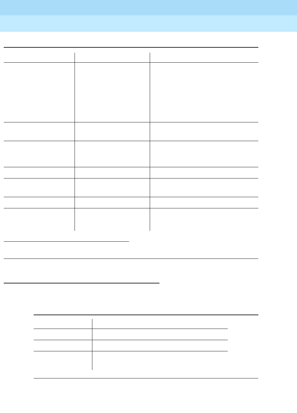
DEFINITYEnterpriseCommunicationsServerandSystem75andSystem85
Terminals and Adjuncts Reference
555-015-201 Issue 11
December 1999
General Information
2-20Technical Specifications
2
External Ringing Tones
The following external ringing tone patterns are generated by the system:
For most currently available voice terminals, the user can select a Personalized
Ringing pattern (out of eight possible ringing patterns). The tone patterns are the
same as those previously described. The three tones are 530 Hz (low [L]), 750 Hz
Call Waiting Tones:
Internal
External or Handled
by Attendant
Priority Call
750 Hz + 20 Hz
750 Hz + 20 Hz
750 Hz + 20 Hz
100 on; not repeated
100 on, 100 off, 100 on;
not repeated
100 on, 100 off, 100 on,100 off,
100 on; not repeated
Coverage Tone 440 Hz 600 on, followed by silence;
not repeated
Confirmation Tone 350 Hz + 440 Hz 100 on, 100 off, 100 on,100 off,
100 on followed by silence;
not repeated
Dial Tone 350 Hz + 440 Hz Continuous
Intercept Tone 480 Hz & 620 Hz 250 on (480 Hz), 250 on (620 Hz);
repeated
Reorder Tone 480 Hz + 620 Hz 250 on, 250 off; repeated
Call Waiting Ringback
Tone 440 Hz + 480 Hz;
440 Hz
1000 on (440 Hz + 480 Hz),
200 on (440 Hz), 2800 off; repeated
* This tone is used with the Busy Verification and Executive Override features and Service Observing
when the warning tone is enabled.
Table 2-4. External Ringing Tone Patterns
Ringing Tone Pattern (In ms)
1 1200 on, 4000 off; repeated
2 400 on, 200 off, 600 on, 4000 off; repeated
3 200 on, 100 off, 200 on, 100 off, 600 on,
4000 off; repeated
Table 2-3. Call Progress Tones — Continued
Tone Frequency Pattern (In ms)
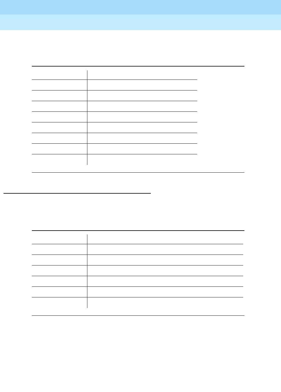
DEFINITYEnterpriseCommunicationsServerandSystem75andSystem85
Terminals and Adjuncts Reference
555-015-201 Issue 11
December 1999
General Information
2-21Technical Specifications
2
(medium [M]), and 1060 Hz (high [H]). The tone sequences are as follows: (Each
of these sequences is prefaced by a medium level tone.)
Indicator Lights Signals
The following light signals are generated by the system for the attendant console
and multi-appearance voice terminals:
Table 2-5. The Eight Personalized Ringing Patterns
Ring Pattern Tone Sequence
1 MMM
2HHH
3LLL
4LHH
5HHL
6HLL
7HLH
8LHL
Table 2-6. Indicator Lights Signals
Lamp Signal Pattern (In ms)
Dark (Off) Off
Lighted (On) On
Flashing 500 on, 500 off; repeated
Fluttering 50 on, 50 off; repeated
Broken Flutter 5 cycles of 50 on, 50 off, followed by 500 off; repeated
Wink 350 on, 50 off; repeated

DEFINITYEnterpriseCommunicationsServerandSystem75andSystem85
Terminals and Adjuncts Reference
555-015-201 Issue 11
December 1999
General Information
2-22Technical Specifications
2

Exposed Port Protection
3-1Out-of-Building Campus Stations
3
DEFINITYEnterpriseCommunicationsServerandSystem75andSystem85
Terminals and Adjuncts Reference
555-015-201 Issue 11
December 1999
3
Exposed Port Protection
All port packs and terminals require unique protection and grounding
arrangements as defined in the checklists (
System 75 Electrical Protection,
Grounding, and Exposure Checklist
, 555-200-120 and
System 85 Electrical
Protection, Grounding, and Exposure Checklist
, 555-103-120). These
arrangements provide an adequate barrier to the potentially damaging voltages
and currents inherent in lightning and power surges present in exposed
applications. Moreover, the National Electrical Code requires that an approved
protector be provided on all exposed circuits.
Ports and terminals that utilize facilities that are subject to disturbances from
lightning, ground potential rises (GPR), or possible contact or induction from
electrical power sources or circuits in excess of 300 volts (RMS) to ground are
classified as exposed. Any ports or terminals served by such exposed facilities
are classified as exposed and require protection at both the port and terminal
ends. The checklists contain flowcharts that are beneficial in determining
exposure status and tables to determine the type of protector required.
Out-of-Building Campus Stations
An out-of-building campus station is a telephone or voice terminal that is not
physically located in the same building as the equipment room, but is located on
the same property. Both analog telephones and digital voice terminals can be
used as out-of-building stations.
Carbon block, or equivalent, protection is required at both building entrances for
analog out-of-building stations. Sneak current protection is also required.
Protection can be provided by a 4-type protector or a 3-type protector plus a
separate sneak current protector. The 4-type protector is equipped with a heat coil
for sneak current protection. The 4-type primary protector is the preferred device.

DEFINITYEnterpriseCommunicationsServerandSystem75andSystem85
Terminals and Adjuncts Reference
555-015-201 Issue 11
December 1999
Exposed Port Protection
3-2Out-of-Building Campus Stations
3
Protection is required at both entrances for digital out-of-building voice terminals.
There are two different types of protectors that can be used to protect digital voice
terminals and digital line circuit packs in an out-of-building environment: the
4C3S-75 Enhanced Protector and the ITW Linx Enhanced Protector.
NOTE:
The 4C3S-75 Enhanced Protector may only be used on Vintage 14 or newer
TN754 Circuit Packs. The 4C3S-75 can be used on all vintages of the
TN754B Circuit Pack. The ITW Linx Enhanced Protector may be used on all
Vintages of the TN754 and TN754B Circuit Packs.
The 4C3S-75 Enhanced Protector is equipped with a heat coil for sneak current
protection and the ITW Linx Enhanced Protector is equipped with replaceable
fuses for sneak current protection.
The maximum range for out-of-building voice terminals is 3,400 feet when using
24 AWG wire and 2,200 feet when using 26 AWG wire. The range can be
extended to 5,000 feet (24 AWG) or 4,000 feet (26 AWG) with the use of a Data
Link Protector (DLP). The DLP is an isolating transformer used to remove
phantom power on the switch side and reintroduce it on the terminal side. When a
DLP is used, the voice terminal must be locally powered by an external power
supply or through the AC power cord provided with some of the 7400 series voice
terminals. The DLP is installed on the equipment side of the protection in both
buildings. In high lightning areas, the DLP may also be installed to provide the
maximum degree of protection and reliability.
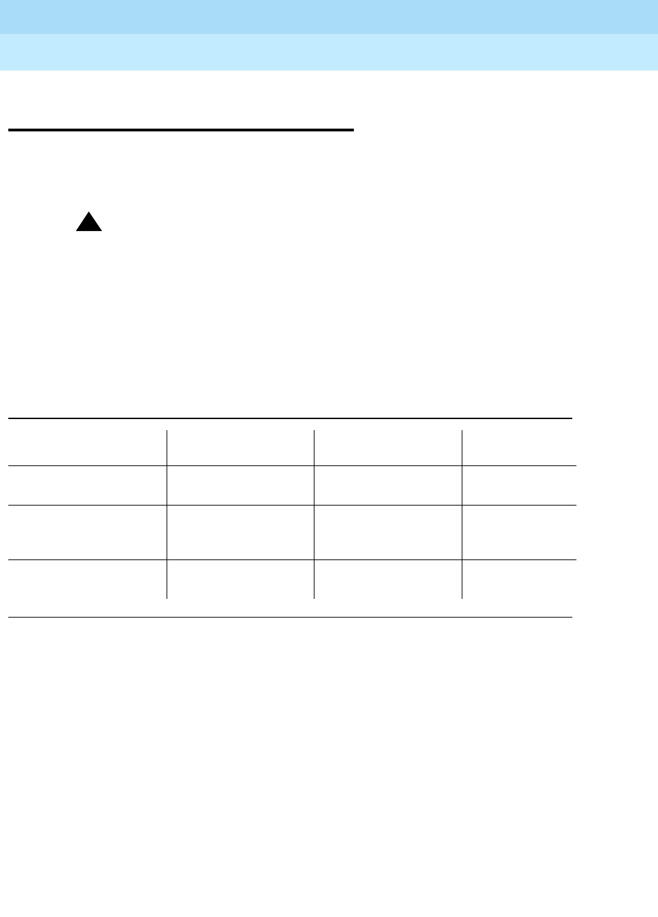
DEFINITYEnterpriseCommunicationsServerandSystem75andSystem85
Terminals and Adjuncts Reference
555-015-201 Issue 11
December 1999
Exposed Port Protection
3-3Recommended Protectors and IROB Protection
3
Recommended Protectors and IROB
Protection
Table 3-1 shows the recommended protectors for the DEFINITY G1, G2, and G3,
DEFINITY ECS, System 75, and System 85. Table 3-2 shows the in-range, out-of-
building (IROB) protection for DEFINITY line circuits and terminals.
!CAUTION:
The following circuit pack and terminal arrangements are not allowed to be
installed in an exposed environment:
1. 7300 Series connected to the TN762B or ANN17 Circuit Pack
2. MET terminals connected to the TN735 Circuit Pack
3. Analog terminals connected to the TN746 Circuit Pack
Table 3-1. Recommended Protectors
Primary
Primary
(with Heat Coil) Enhanced Primary Secondary
3B1A
(carbon) 4B1C
(carbon) 4C3S-75
(solid state) 79A Fuse
3B1E-W
(wide-gap gas tube) 4B1E-W
(wide-gap gas tube) ITW Linx
(gas tube avalanche
suppress)
SCP-1
3C1S
(solid state) 4C1S
(solid state)
DEFINITYEnterpriseCommunicationsServerandSystem75andSystem85
Terminals and Adjuncts Reference
555-015-201 Issue 11
December 1999
Exposed Port Protection
3-4Recommended Protectors and IROB Protection
3
* Key to Abbreviations:
P = Primary; EP = Enhanced Primary
Notes:
1. Primary protection with heat coils for sneak protection are coded with the number 4as the first
numeric. DEFINITY ports require sneak current protection for IROB terminal installations.
2. The TN754, V1 through V13 may be installed with either the DLP and primary protector or the
ITW Linx Enhanced Primary protector. These vintages may not be installed with the 4C3S-75
Enhanced Primary protector.
3. The 4C3S-75 Enhanced Protector may only be used on Vintage 14 or newer TN754 Circuit
Packs. The ITW Linx Enhanced Protector may be used on all Vintages of the TN754 Circuit
Pack.
4. The TN556 Circuit Pack requires Enhanced Primary protection at the port and Primary (3- or
4-type) protection at the terminal.
For more information on exposed port protection, refer to:
■
DEFINITY Communications System Generic 1 and Generic 3 Wiring
,
555-204-111
■
DEFINITY Communications System Generic 2 and System 85 Wiring
,
555-104-630
Table 3-2. IROB Protection
Circuit Packs Terminal Required Protector*
SN224 7203,
7205,
MET
EP
SN228B,
SN229
2500 Series,
2500DMGC,
7100 Series
P1
TN742,
TN746B,
TN769
500 Series,
2500 Series,
7100 Series
P1
SN270 7400 Series EP
TN754 7400 Series (ITW)2
TN754, V14 7400 Series EP3
TN556 T. Term EP and P4

Adjunct Power
4-1
4
DEFINITYEnterpriseCommunicationsServerandSystem75andSystem85
Terminals and Adjuncts Reference
555-015-201 Issue 11
December 1999
4
Adjunct Power
Power for several of the adjuncts must be provided locally at the voice terminal or
from a satellite closet through the terminal wiring. The following power supplies
are currently recommended:
■The 1151A1 Power Unit and the 1151A2 Power Unit with Battery Holdover
have replaced the MSP-1 (WP92464L1) Power Supply, the KS-22911 L1/2,
329A, and 353A DC power supplies, and the 2012D AC transformer. The
1151A1 and 1151A2 with Battery Holdover can be used to supply local
power to ISDN-T 65xx, 75xx, and 85xx series voice terminals connected to
a DEFINITY Communications System Generic 1, Generic 2, Generic 3, a
DEFINITY ECS, and the DCP 7444 and 8434/8434DX voice terminals
which need auxiliary power for their vacuum fluorescent displays. You will
also need auxiliary power if you are using a 6400 Series telephone or an
8411 voice terminal or if you have a ZE801A or an XM24 expansion
module connected to your voice terminal or telephone. These power units
can also supply auxiliary power to adjunct equipment such as the S201A,
CS201A, or SoundPoint speakerphones or a 500A1 Headset Adapter
attached to any currently manufactured analog, DCP, or ISDN-T voice
terminal equipped with an Adjunct jack. For more information on the MSP-1
and the newer 1151A1 and 1151A2 power supplies, see the short section
with connection diagrams later in this section.
■The ISDN 1145B1 Bulk Power Unit, 1146B Power Distribution Unit, and the
2.5/5.0 A.H. back-up batteries provide an uninterruptible power source for
ISDN telephones and terminals, NT1s, terminal adjuncts, and other
customer premises equipment. During AC power interruptions, batteries
are automatically switched on to provide continuous power to the load.

DEFINITYEnterpriseCommunicationsServerandSystem75andSystem85
Terminals and Adjuncts Reference
555-015-201 Issue 11
December 1999
Adjunct Power
4-2
4
The distribution of power to the terminal equipment is provided by the
1146B distribution unit. The 1146B provides 32 standard 110 connections
to the load with overcurrent protection and alarm lights. The 1145B1/1146B
power arrangement is compact (measuring only 6.5 inches deep),
lightweight, plastic enclosed, and designed for easy wall- or rack-mounting.
During normal operation, the power supply/charger provides DC power to
the load via the distribution unit while maintaining the battery in a fully
charged condition. The power system continuously monitors systems
conditions with the status displayed on the front panel of the power supply
and distribution unit.
The following power supplies and transformers are NO LONGER recommended.
They have been replaced by the 1151A1 and 1151A2 power units and the 1145B1
bulk power unit described above.
■2012D AC transformer — can be used locally or in a satellite closet to
power a single 18 volt headset adapter or speakerphone.
■KS-22911, L2 DC power supply — can be used locally or in a satellite
closet to power a headset adapter or speakerphone plus one additional
adjunct. This unit has a 48 volt power output of 10 watts.
■KS-21239, L4, L5 AC transformer — can be used locally or in a satellite
closet to power a single 24 volt speakerphone-dialer.
■PS3081096 AC transformer — can be used locally or in a satellite closet to
power the 24 V S201A or S203A speakerphones.
■329A DC power supply — can be used locally or in a satellite closet and is
capable of supplying power to any number of adjuncts that may be added
to a digital voice terminal. This unit has a power output of 25 watts.
■346A modular bulk DC power supply — can be used in a satellite closet
only and is capable of supplying power to any number of adjuncts that may
be added to a digital voice terminal. This unit provides switch-selectable
options for four outputs at 10 watts or two outputs at 20 watts.
■85B1-49 power unit — can be used locally or in a satellite closet to power
the 4A speakerphone.
■95B1 power unit — can be used locally or in a satellite closet to power a
2870A1 automatic dialer.
■353 DC Power Supply — can be used locally only. It is designed to supply
power to ISDN-BRI stations and their adjuncts. It has a power output of 12
watts.
■945 Bulk DC Power Supply — can be used in a satellite closet only. It is
designed to power ISDN-BRI stations and their adjuncts. It can optionally
be equipped with a battery to provide terminal operation for a limited time in
case of an AC power failure. Up to 26 ISDN-BRI terminals can be
supported by the 945 power supply.

DEFINITYEnterpriseCommunicationsServerandSystem75andSystem85
Terminals and Adjuncts Reference
555-015-201 Issue 11
December 1999
Adjunct Power
4-3Information on the Older Power Supplies
4
Information on the Older Power
Supplies
The following diagram (Figure 4-1) shows the connections with the older power
supplies including the MSP-1.
NOTE:
The 1151A1 and 1151A2 replace the MSP-1, the KS-22911 L1/2, 329A, the
353A DC power supplies, and the 2012D AC transformer.
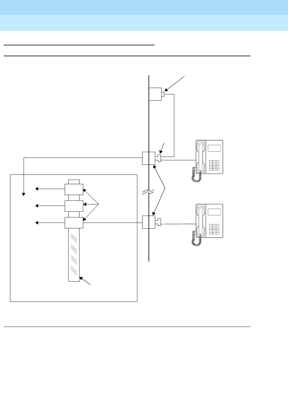
DEFINITYEnterpriseCommunicationsServerandSystem75andSystem85
Terminals and Adjuncts Reference
555-015-201 Issue 11
December 1999
Adjunct Power
4-4Information on the Older Power Supplies
4
The Power Supplies Prior to the MSP-1
Figure 4-1. Local and Satellite Power Sources for Voice Terminals Adjuncts
Wall
PS
Local Power Supply:
2012D or 329A or
KS-22911,L2 or
KS-21239,L4/L5
or 353 or DS3081096
400B2
Terminal
Terminal
Information
Outlet
PS
PS
PS
To
Vertical
Trough
KS-22911,
945, 329A,
or 346A
Power Supplies
AC Power Strip
Satellite Location

DEFINITYEnterpriseCommunicationsServerandSystem75andSystem85
Terminals and Adjuncts Reference
555-015-201 Issue 11
December 1999
Adjunct Power
4-5Information on the Older Power Supplies
4
One of these power supplies must be used for each voice terminal equipped with
one or more adjuncts. Each of these power supplies (except the 95B1) has a
maximum cable distance of 250 feet (76 m) between the power supply and the
adjunct(s). The maximum cable distance for the 95B1 is 150 feet (45m). Voice
terminal adjuncts and modules are not operational during interruptions of
commercial AC power unless their power supplies are also powered through
standby power of other essential AC power service.
The 329A and 346A power supplies clustered in a satellite closet are normally
mounted on AC power strips. Power to these strips is provided from a dedicated
120 volt AC, 60-Hz, 20-ampere circuit breaker and feeder either directly or
through a 543A telephone power unit. The 543A unit provides an inductive filter to
limit inrush current on the feeder. It comes equipped with an AC power cord which
plugs into the dedicated feeder and provides four receptacles for AC power strips.
The 945 bulk power system is usually rack mounted and is intended to be located
in an equipment room or satellite closet. It is optionally made up of the following
components:
■945-1 bulk power supply unit.
■945-2 battery reserve unit.
■945-3 system enclosure, equipped with one or two 945-1 and/or a 945-2.
■945-4 single enclosure for 945-1 unit.
Several power supplies and connection schemes are available for providing
auxiliary adjunct power when it is required. Regardless of its source, auxiliary
power is introduced into a pair of spare leads in the individual voice terminal’s line,
at some wiring interface. The auxiliary power is fed into the terminal on the
mounting line cord. From the terminal, power is distributed to the adjunct(s). An
auxiliary power source is usually mounted in a satellite closet or adjacent to the
voice terminal’s wall jack.
The MSP-1 Power Supply
The MSP-1 (WP92464L1) Power Supply can be used to supply local power to
ISDN-T 65xx, 75xx, and 85xx series voice terminals connected to a DEFINITY
Communications System G1, G2, and G3, a DEFINITY ECS, and to the DCP
7444 and 8434/8434DX voice terminals which need auxiliary power for their
vacuum fluorescent displays. The MSP-1 can also supply auxiliary power to
adjunct equipment such as the S201A and CS201A speakerphones or a 500A
Headset Adapter attached to any currently manufactured analog, DCP, or ISDN-T
voice terminal equipped with an Adjunct jack.
!CAUTION:
The MSP-1 Power Supply can be used only with telecommunications
equipment, indoors, in a controlled environment.

DEFINITYEnterpriseCommunicationsServerandSystem75andSystem85
Terminals and Adjuncts Reference
555-015-201 Issue 11
December 1999
Adjunct Power
4-6Information on the Older Power Supplies
4
NOTE:
One power supply will support one telephone with or without an adjunct.
The maximum loop range between the telephone and the power supply is
250 feet.
This power supply replaces the KS-22911-L1/2, 329A, and 353A DC Power
Supplies and the 2012D AC Transformer.
The MSP-1 power supply has a single output of -48 volt DC, 0.4 amperes, and can
operate from either a 120 VAC 60 Hz power source (105 to 129 VAC) or a
220/230/240 50 Hz power source (198 to 264 VAC). Input voltage selection is
automatic; that is, the power supply adjusts itself for the type of input voltage. The
output capacity is 19.2 watts.
Contents of the MSP-1 Package (and Comcodes)
The MSP-1 package includes the following items: (Comcodes are provided for
additional orders)
■One MSP-1 power supply (Comcode: 406743419)
■One 6-foot, 7-inch input power cord (Comcode: 403271117)
■One 7-foot D8W cord (Comcode: 103786786)
■Double-sided adhesive fastener strips for mounting the power supply on a
flat vertical surface (Comcode: 406824789)
■Printed instructions
Connecting the Power Supply
The power output is provided through 2 modular jacks on the power supply.
These jacks are labeled, from left to right:
The - and + numbers under “PHONE” and “OTHER” refer to the pins on which
power is present and the polarity of that power.
The PHONE and LINE jacks are 8-pin female non-keyed 657-type jacks that can
accept D4, D6, and D8 modular plug cables. The OTHER jack is a 6-pin female
non-keyed 657-type jack.
The following local powering arrangements, shown in Figures 4-2 and 4-3, can be
used with the MSP-1 power supply.
Phone Other Line
-7 +8 -2 +5
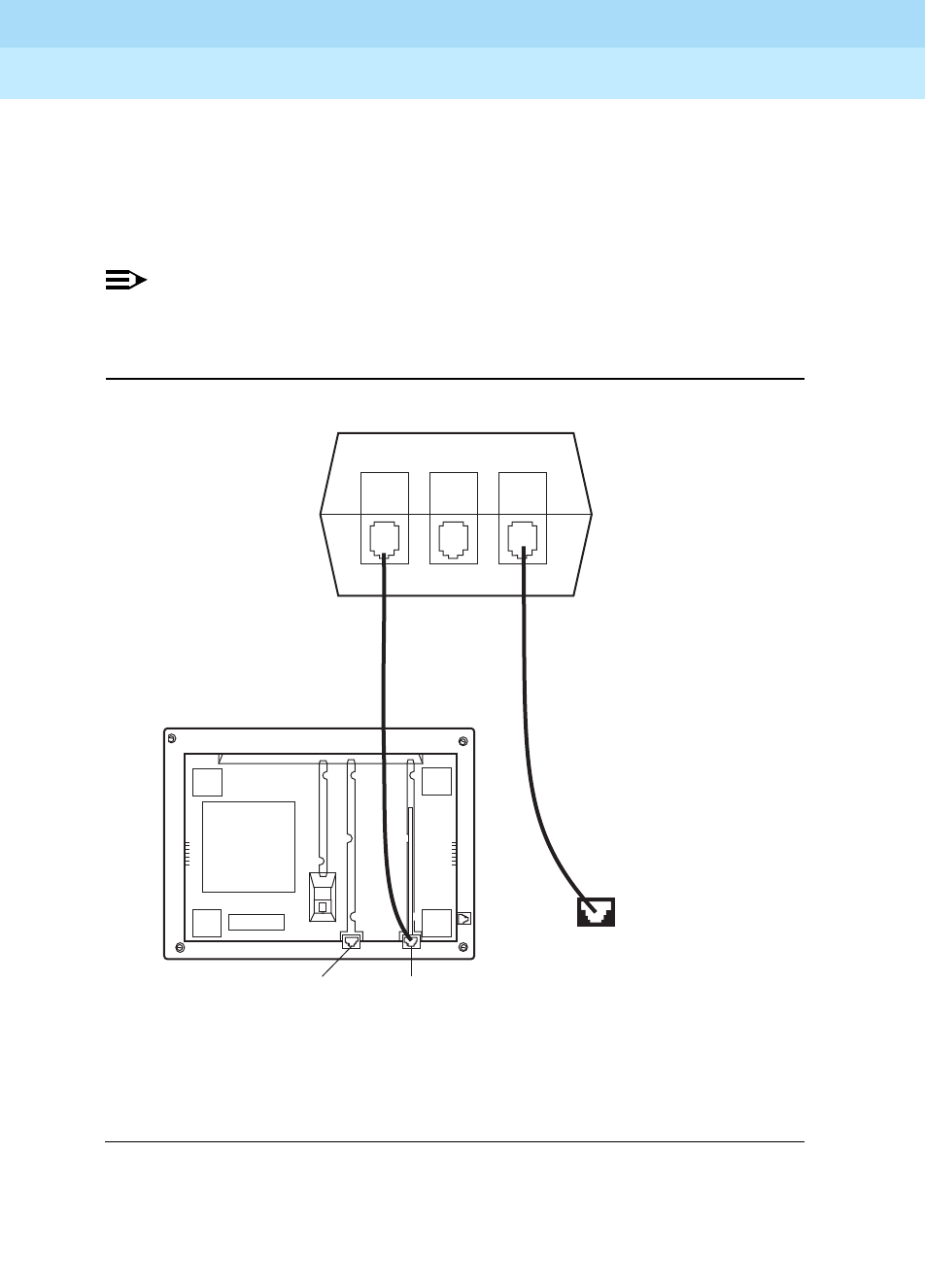
DEFINITYEnterpriseCommunicationsServerandSystem75andSystem85
Terminals and Adjuncts Reference
555-015-201 Issue 11
December 1999
Adjunct Power
4-7Information on the Older Power Supplies
4
■Figure 4-2 shows the local powering arrangement for: ISDN voice
terminals; the DCP 7444 and 8434DX voice terminals’ VF displays; and
adjuncts connected to all telephones except the 8102.
■Figure 4-3 shows the local powering arrangement for adjuncts connected
to the 8102 telephone.
NOTE:
The type of cord(s) needed to make these connections are designated in
each drawing.
Figure 4-2. Local Powering Arrangement (Using the MSP-1) for: ISDN-T
Voice Terminals; the DCP 7444 and 8434/8434DX Voice Terminals
(for their VF Displays); and Adjuncts Connected to All Telephones
Except the 8102
D8W
cord
Line jack
D4BU cord
(for analog
telephones)
or
D8W cord
(for DCP and
ISDN-T voice
terminals)
Bottom view of
voice terminal/telephone
(7444 shown here)
MSP-1
Power Supply
PHONE
-7 +8
OTHER LINE
-2 +5
Wall jack
Adjunct jack
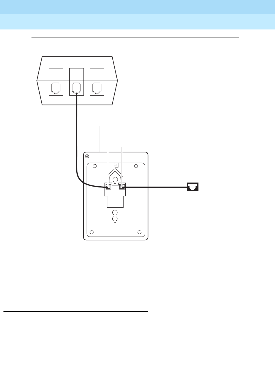
DEFINITYEnterpriseCommunicationsServerandSystem75andSystem85
Terminals and Adjuncts Reference
555-015-201 Issue 11
December 1999
Adjunct Power
4-8The 1151A1 and 1151A2 Power Units
4
Figure 4-3. Local Powering Arrangement (Using the MSP-1) for Adjuncts
Connected to the 8102 Analog Telephone
The 1151A1 and 1151A2 Power Units
The 1151A1 power supply is a single output 48 volt DC, 20 watt power supply. The
1151A1 operates from nominal AC input voltage (85 to 132 or 176 to 264) 50 or 60
Hz. This power supply can be desk-mounted and wall-mounted.
The 1151A2 power supply also is a single output 48 volt DC, 20 watt power
supply. However, this power supply has battery holdover. The power supply
operates from nominal AC input voltage (85 to 132 or 176 to 264) 50 or 60 Hz.
Input voltage selection is automatic; that is, the power supply adjusts itself for the
D4BU
cord
Wall Jack
D4BU cord
or
2–wire cord
Line jack
Bottom view of
the 8102 telephone
MSP-1
Power Supply
PHONE
-7 +8
OTHER LINE
-2 +5
Adjunct jack
(on the rear
of telephone)
Power jack

DEFINITYEnterpriseCommunicationsServerandSystem75andSystem85
Terminals and Adjuncts Reference
555-015-201 Issue 11
December 1999
Adjunct Power
4-9The 1151A1 and 1151A2 Power Units
4
type of input voltage. When AC power fails, the battery will provide 15 minutes of
holdover at full load (20 watts) or 8 hours at light load (2 watts).
The 1151A1 and 1151A2 power supplies can be used to supply local power to
ISDN-T 65xx, 75xx, and 85xx series voice terminals connected to a DEFINITY
Communications System G1, G2, and G3, a DEFINITY ECS, and to the DCP
7444 and 8434/8434DX voice terminals which need auxiliary power for their
vacuum fluorescent displays. You also need auxiliary power if you are using an
8411 voice terminal or if your voice terminal has a ZE801A or XM24 expansion
module connected to it. These power supplies can also supply auxiliary power to
adjunct equipment such as the S201A, CS201A, or SoundPoint speakerphones or
a 500A1 Headset Adapter attached to any currently manufactured analog, DCP, or
ISDN-T voice terminal equipped with an Adjunct jack.
!CAUTION:
The 1151A1 and 1151A2 Power Supplies can be used only with
telecommunications equipment, indoors, in a controlled environment.
NOTE:
One 1151A1 or 1151A2 Power Supply will support two or more telephones
with or without an adjunct that does not exceed 20 watts of power.
The maximum loop range between the telephone and the power supply is
250 feet.
Both the 1151A1 and the 1151A2 power supply have a green light (labeled
POWER ON) that shows the unit has power on the PHONE mod jack pins 7
and 8 when AC power is applied.
The 1151A2 power supply also has a yellow light that shows that the
battery is charging when AC power is applied. When the battery is fully
charged, the yellow light is off.
Contents of the 1151A1 and 1151A2 Packages
(and Comcodes)
The 1151A1 and 1151A2 packages include the following items: (Comcodes are
provided for additional orders)
■One 1151A1 power supply (Comcode: 107787129) or one 1151A2 power
supply (Comcode: 107787111)
■One power cord NEMA 5-15P
■One 7-foot D8W cord (Comcode: 103786786)
■Printed instructions

DEFINITYEnterpriseCommunicationsServerandSystem75andSystem85
Terminals and Adjuncts Reference
555-015-201 Issue 11
December 1999
Adjunct Power
4-10The 1151A1 and 1151A2 Power Units
4
Connecting the Power Supply
The power output is provided through 1 modular jack on the power supply.
These jacks are labeled, from left to right:
The - and + numbers under “PHONE” refer to the pins on which power is present
and the polarity of that power.
The PHONE and LINE jacks are 8-pin female non-keyed 657-type jacks that can
accept D4, D6, and D8 modular plug cables.
The following local powering arrangement, shown in Figures 4-4, can be used
with the 1151A1 and 1151A2 power supplies.
Phone Line
-7 +8
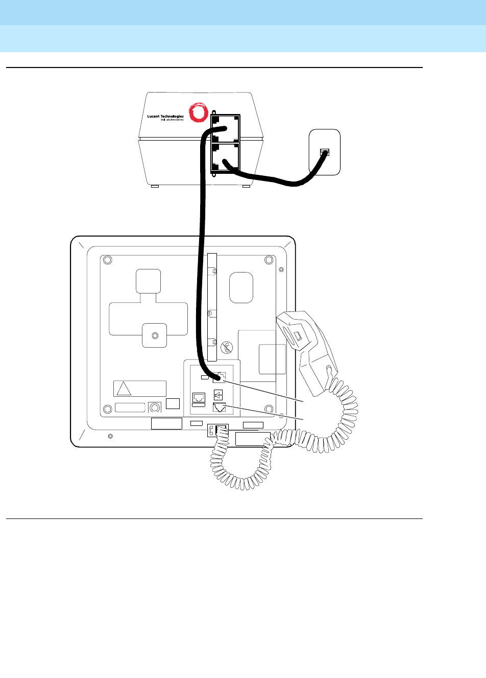
DEFINITYEnterpriseCommunicationsServerandSystem75andSystem85
Terminals and Adjuncts Reference
555-015-201 Issue 11
December 1999
Adjunct Power
4-11The 1151A1 and 1151A2 Power Units
4
Figure 4-4. Local Powering Arrangement (Using the 1151A1/A2) for: ISDN-T Voice
Terminals; the DCP 7444 and 8434/8434DX Voice Terminals (for their VF
Displays); the 8411; any 8400 or 6400 Series Telephone with an Attached
Expansion Module; and Adjuncts Connected to All Telephones Except the
8102
Adjunct
Line jack
!
EX MOD
LINE
jack
1151A1/2 Power Unit
POWER ON
W/Battery Holdover
PHONE
-7 +8
LINE
CHARGING
Wall jack

DEFINITYEnterpriseCommunicationsServerandSystem75andSystem85
Terminals and Adjuncts Reference
555-015-201 Issue 11
December 1999
Adjunct Power
4-12The 1151A1 and 1151A2 Power Units
4

Administration
5-1
5
DEFINITYEnterpriseCommunicationsServerandSystem75andSystem85
Terminals and Adjuncts Reference
555-015-201 Issue 11
December 1999
5
Administration
This section contains some of the information necessary to administer the
different voice terminals connected to a DEFINITY Communications System
Generic 1, Generic 2, and Generic 3, a DEFINITY Enterprise Communications
Server (ECS), and to a System 75, or System 85. It also provides the caveats
required when administering some of the newer voice terminals to the older
systems. Other administration information for the DEFINITY G1 and G3 or
System 75 is provided in the DEFINITY G1 and G3 and System 75
Implementation and Administration manuals. The administration information for
DEFINITY G2 and System 85 is provided in the
System 85 and DEFINITY G2
Translation Service Manual
.
NOTE:
The sections of this manual which describe the newer voice terminals
provide detailed information on administering that voice terminal. In most
cases, diagrams of the button numbering schemes are also provided. For
example, if you want to administer an 8410 voice terminal, see the section
on the 8410 Voice Terminal under the tab labeled 8400 Series.

DEFINITYEnterpriseCommunicationsServerandSystem75andSystem85
Terminals and Adjuncts Reference
555-015-201 Issue 11
December 1999
Administration
5-2Aliasing
5
Aliasing
When some of the newer voice terminals are used with some older versions of the
switches, the administration procedures of the switch does not allow for the use of
the new terminals. These new terminals must be administered using the
administration procedures of a similar older terminal. This is called “aliasing” a
set.
When aliasing is used to administer a voice terminal, often the “old” screen used
in administering buttons and features displays more buttons than can actually be
assigned to the new terminal. These differences are provided in this section also.
The following tables list the aliases used in administering the terminals. If the
terminal you are administering is not listed in the tables, then it is administered as
itself in all versions of the switch.
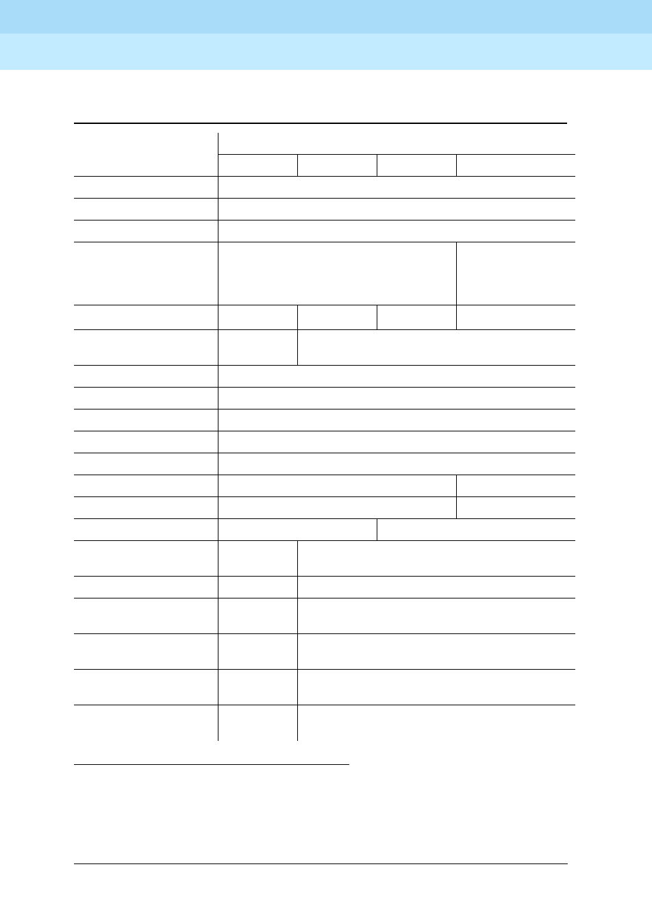
DEFINITYEnterpriseCommunicationsServerandSystem75andSystem85
Terminals and Adjuncts Reference
555-015-201 Issue 11
December 1999
Administration
5-3Aliasing
5
S = Administered as Self
X = Not Allowed
DD = Digital Display Module
Table 5-1. DEFINITY G1 and G3, DEFINITY ECS, and System 75 Voice
Terminal Administration
System
Voice Terminal S75 R1V1 S75 R1V2 S75 R1V3 G1 and G3
8101/8102/8110 2500 with Message Waiting
6201 2500
6210/6220/6230 2500 with Message Waiting
6402, 6402D, 6408,
6408+, 6408D, 6408D+,
6416D+, 6424D+
X Administered as
itself on DEFINITY
ECS Release 6.1 (or
later)
7102A 7101A
7104A 7101A
or 2500*
* If equipped with a message waiting adjunct, administer as a 7101A; otherwise, administer as 2500.
S
7203H X
7205H X
“MERLIN”†SMALL
† MERLIN Communications System
7303S
“MERLIN” MEDIUM 7305S
“MERLIN” LARGE 7305S
7401D 7403D S
7401 Plus 7403D 7401D
7402 Plus 7403D 7410D
7406 7405D
DD
S
7406BIS 7405D S
7406 Plus 7405D 7406D
or 7406BIS
7407D 7405D
DD
S
Enhanced 7407D 7405D
DD
7407D
7407 Plus 7405D
DD
7407D
Continued on Next Page
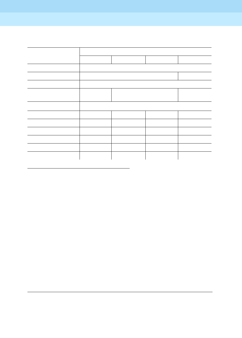
DEFINITYEnterpriseCommunicationsServerandSystem75andSystem85
Terminals and Adjuncts Reference
555-015-201 Issue 11
December 1999
Administration
5-4Aliasing
5
DD = Digital Display Module
Table 5-1. DEFINITY G1 and G3, DEFINITY ECS, and System 75
Voice Terminal Administration — Continued
System
Voice Terminal S75 R1V1 S75 R1V2 S75 R1V3 G1 and G3
7410 7403D
7410 Plus 7403D 7410D
7434 7405D
7444 7405D
DD
7405D
or 7407D*
* CAVEATS for administration of the 7444 voice terminal:
If the 7444 voice terminal is administered as a 7405D or a 7407D, the following caveats apply:
■Only 10 call appearance buttons can be administered with two lights, a red and a green light.
■If the voice terminal is administered as a 7407D, the S1 switch on the back of the 7444 voice terminal must
be in the OFF position.
When the 7444 voice terminal is administered as a 7405D or a 7434 voice terminal, the following caveats apply:
■The S1 switch on the back of the 7444 voice terminal must be in the ON position.
■Only one line of the display will show switch-related information.
When a 7444 is administered as a 7434, DEFINITY G1 allows a maximum of 10 appearances of the primary line
while DEFINITY G2 allows a maximum of 12 appearances. Each switch handles appearances of other lines (that
is, lines used in Bridging, Call Pickup, etc.) in a different manner. Information about administering these
appearances can be found in switch documentation and help screens.
7434D
or 7407D*
8403 7405†
† If the 8403 is connected to a DEFINITY G3V3 (and later), the 8403 can be administered as itself.
8405B/8405B Plus 7403 7410‡
‡ If the 8405B or 8405B Plus is connected to a DEFINITY G3i or G3r, it can be administered as a 7410 Plus. If the
8405B or 8405B Plus is connected to a DEFINITY G3V3 (or later), the set can be administered as an 8410B. If
the 8405D or 8405D Plus is connected to a DEFINITY G3V3 (or later), the set can be administered as an 8410D.
8405D/8405D Plus 7403 7410‡
8410B 7403 7410§
§ If the 8410B is connected to a DEFINITY G3i or G3r, it can be administered as a 7410 Plus. If the 8410B or 8410D
is connected to a DEFINITY G3V3 (or later), the set can be administered as itself.
8410D 7403 7410§
8411B 7403 7410¶
¶ If the 8411B is connected to a DEFINITY G3i or G3r, it can be administered as a 7410 Plus. If the 8411B is
connected to a DEFINITY G3V3 (or later), the set can be administered as an 8410B. If the 8411D is connected
to a DEFINITY G3V3 (or later), the set can be administered as an 8410D.
8411D 7403 7410¶
Continued on Next Page
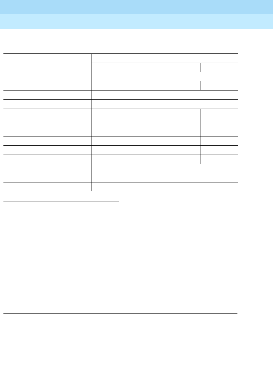
DEFINITYEnterpriseCommunicationsServerandSystem75andSystem85
Terminals and Adjuncts Reference
555-015-201 Issue 11
December 1999
Administration
5-5Aliasing
5
S = Administered as Self
X = Not Allowed
+D = with Display Module
+F = with Feature Key Module
Table 5-1. DEFINITY G1 and G3, DEFINITY ECS, and System 75
Voice Terminal Administration — Continued
System
Voice Terminal S75 R1V1 S75 R1V2 S75 R1V3 G1 and G3
8434/8434DX (for extra features)*
* CAVEATS for administration of the 8434 voice terminal:
The 8434 and 8434DX may be aliased as a 7405+D+F to support all system features. However, in this case, while all the call
appearance/feature buttons AND the softkey features will be functional, there can be a maximum of only 10 call appearances.
On the 7405, the Display Module is a 1-line display, and thus the 1-line display option should be selected. On some systems,
the 8434 and 8434DX can be aliased as a 7434+D or a 7444 to support coverage. In this case, there can be up to 34 call
appearances (including bridged call appearances), but the 15 softkey features will NOT be functional because the Feature Key
Module is not allowed with the 7434 or 7444. On the 7434, the Display Module is a 1-line display, and thus the 1-line display
option should be selected. If the set is administered as a 7444, it can be optioned for a 2-line display.
An 8434 or 8434DX connected to a DEFINITY G3V2 can be administered as a 7444; an 8434 or 8434DX connected to a
DEFINITY G3V3 (or later) can be administered as itself.
7405+D+F
8434/8434DX (for additional coverage)*X 7434+D
602 CALLMASTER X X S
CALLMASTER II and III X X 602 CALLMASTER
7505 ISDN X S
7506 ISDN X S
7507 ISDN X S
8503T X S
8510T X S†
† An 8510T voice terminal connected to a DEFINITY G1 or G3 can be administered as itself, but an 8510 data terminal must be
administered as a 7507.
8520T X S
MDC 9000 7303S Hybrid‡
‡ A MDC 9000 Cordless Telephone or a MDW 9000 Wireless Telephone connected to a DEFINITY G3V3 (or later) can be
administered as itself.
MDW 9000 7303S Hybrid‡
MDW 9031DCP 8410D
DEFINITYEnterpriseCommunicationsServerandSystem75andSystem85
Terminals and Adjuncts Reference
555-015-201 Issue 11
December 1999
Administration
5-6Aliasing
5
S = Administered as Self
X = Not Allowed
PC = Personal Computer
DD = Digital Display Module
DM = Data Module
TDM=TrunkDataModule
PDM = Processor Data Module
Table 5-2. DEFINITY G1 and G3, DEFINITY ECS, and System 75 Terminal
and Module Administration
System
PCs and
Digital Modules S75 R1V1 S75 R1V2 S75 R1V3 G1 and G3
PC/PBX Platform 7405D
DD and DM
PC
MPDM S
MTDM S
7400A DM PDM or TDM (modem pool only) S
7400B and 7400B Plus DM PDM (data only) or DM (voice and data) S
High Speed Link PDM
3270A DCP PDM
3270C DCP PDM
3270T DCP PDM
PC/ISDN Platform X X X X
DEFINITYEnterpriseCommunicationsServerandSystem75andSystem85
Terminals and Adjuncts Reference
555-015-201 Issue 11
December 1999
Administration
5-7Aliasing
5
X = Not Allowed
A = Administered as Analog On-premises or Off-premises
S = Administered as Self
DD = Digital Display Module
DM = Data Module (DTDM or ADS)
Table 5-3. DEFINITY G2 and System 85 Voice Terminal Administration
System
Voice Terminal S85 R2V1 S85 R2V2 S85 R2V3 S85 R2V4 G2
500 A
2500 A
2500 YMGK A
8101/8102/8110 A
6201/6210/6220/6230
7101A A
7102A A
7102 Plus A
7103A A
7104A A
10 MET 7203H
20 MET 7205H
30 MET 7205H
“MERLIN” SMALL X
“MERLIN” MEDIUM 7303S
“MERLIN” LARGE 7305S
7401D 7403D S
7401 Plus 7403D 7401D
7402 Plus 7403D 7410D
7404 7403D DM S
7406D 7405D DD S
7406BIS 7405D DD S
7406 Plus 7405D DD 7406D or 7406BIS
7407D 7405
DD
S
Enhanced 7407D 7405D
DD
7407D
7407 Plus 7405D
DD
7407D
Continued on Next Page
DEFINITYEnterpriseCommunicationsServerandSystem75andSystem85
Terminals and Adjuncts Reference
555-015-201 Issue 11
December 1999
Administration
5-8Aliasing
5
S = Administered as Self
DD = Digital Display Module
Table 5-3. DEFINITY G2 and System 85 Voice Terminal Administration — Continued
System
Voice Terminal S85 R2V1 S85 R2V2 S85 R2V3 S85 R2V4 G2
7410D 7403D S
7410 Plus 7403D 7410D
7434D 7405D S
7444 7405D DD 7405D DD
or 7407D*7434D
or 7407D*
* CAVEATS for administration of the 7444 voice terminal:
If the 7444 voice terminal is administered as a 7405D or a 7407D, the following caveats apply:
■Only 10 call appearance buttons can be administered with two lights, a red and a green light.
■If the voice terminal is administered as a 7407D, the S1 switch on the back of the 7444 voice terminal must be in the OFF
position.
When the 7444 voice terminal is administered as a 7405D or a 7434 voice terminal, the following caveats apply:
■The S1 switch on the back of the 7444 voice terminal must be in the ON position.
■Only one line of the display will show switch-related information.
When a 7444 is administered as a 7434, DEFINITY G1 allows a maximum of 10 appearances of the primary line while DEFINITY
G2 allows a maximum of 12 appearances. Each switch handles appearances of other lines (that is, lines used in Bridging, Call
Pickup, etc.) in a different manner. Information about administering these appearances can be found in switch documentation
and help screens.
8403 7405
8405B/8405B Plus 7403 7410D
8405D/8405D Plus 7405+D
8410B 7403 7410D
8410D 7405+D
8411B 7403 7410D
8411D 7405+D
Continued on Next Page
DEFINITYEnterpriseCommunicationsServerandSystem75andSystem85
Terminals and Adjuncts Reference
555-015-201 Issue 11
December 1999
Administration
5-9Aliasing
5
X = Not Allowed
A = Administered as Analog On-premises or Off-premises
S = Administered as Self
Table 5-3. DEFINITY G2 and System 85 Voice Terminal Administration — Continued
System
Voice Terminal S85 R2V1 S85 R2V2 S85 R2V3 S85 R2V4 G2
8434/8434DX
(for extra features)*
* CAVEATS for administration of the 8434 voice terminal:
The 8434 may be aliased as a 7405+D+F to support all system features. However, in this case, while all the call
appearance/feature buttons AND the softkey features will be functional, there can be a maximum of only 10 call appearances.
On the 7405, the Display Module is a 1-line display, and thus the 1-line display option should be selected.
On some systems, the 8434 can be aliased as a 7434+D or a 7444 to support coverage. In this case, there can be up to 34 call
appearances (including bridged call appearances), but the 15 softkey features will NOT be functional because the Feature Key
Module is not allowed with the 7434 or 7444. On the 7434, the Display Module is a 1-line display, and thus the 1-line display
option should be selected. If the set is administered as a 7444, it can be optioned for a 2-line display.
7405+D+F
8434/8434DX (for
additional coverage)*X 7434+D
602 CALLMASTER X S
CALLMASTER II and III X 602 CALLMASTER
7505 ISDN X S
7506 ISDN X S
7507 ISDN X S
8503T X 7505
8510T X 7507
8520T X 7507
MDC 9000 7303S Hybrid
MDW 9000 7303S Hybrid
MDW 9031 8410D
DEFINITYEnterpriseCommunicationsServerandSystem75andSystem85
Terminals and Adjuncts Reference
555-015-201 Issue 11
December 1999
Administration
5-10Aliasing
5
S = Administered as Self
X = Not Allowed
PC = Personal Computer
DD = Digital Data Module
DM = Data Module
PDM = Processor Data Module
TDM=TrunkDataModule
GTA = Generalized Terminal Administration (see System 85 and DEFINITY G2
Button and Feature Caveats section)
Table 5-4. DEFINITY G2 and System 85 Terminal and Module Administration
System
Display Terminals
and Digital Modules S85 R2V1 S85 R2V2
S85
R2V3
S85
R2V4 G2
PC/PBX Platform 7405D
DD and DM
PT 510D PC
BCT 513 X EIA PORT
MPDM PDM
MTDM TDM
7400A DM PDM or TDM (modem pool only) S
7400B and 7400B Plus DM PDM (data only) or DM (voice and data) S
7500B DM X S
High Speed Link PDM
3270A DCP PDM
3270C DCP PDM
3270T DCP PDM
PC/ISDN Platform X GTA
DEFINITYEnterpriseCommunicationsServerandSystem75andSystem85
Terminals and Adjuncts Reference
555-015-201 Issue 11
December 1999
Administration
5-11Button and Feature Caveats
5
Button and Feature Caveats
System 75, DEFINITY G1 and G3,
and DEFINITY ECS
Table 5-5. Button and Feature Caveats for DEFINITY G1 and G3 and System 75
Terminal Aliased As Switch Release
Buttons
that Do
NOT
Exist*
* Do not assign features to these buttons.
Note 1:
7406D02A, 7406D04A, and 7406D06A aliased as 7405D;
7406D02A, 7406D04A, and 7406D06A with 7400B Plus aliased as 7405D with DM;
7406D01A, 7406D03A, and 7406D05A aliased as 7405D with DD;
7406D01A, 7406D03A, and 7406D05A with 7400B Plus aliased as 7405D with DM and DD;
7406D01A and 7406D02A with Z703A DSU aliased as 7405D with DM and DD.
Note 2:
Reserved for Speaker and Mute.
Note 3:
Not supported in earlier releases.
Note 4:
These buttons are used for the Log in and Release features.
Do NOT
Assign
Features to
Button(s)
7401D 7403D R1V1—R1V3 10 —
7406D01A—
7406D04A
7405D
(SeeNote1)
R1V1 6—10,
19—24
—
7406D05A,
7406D06A
7405D
(SeeNote1)
R1V1 6—10,
19—24
2, 3
(See Note 2)
Self R1V2—R1V3,
G1
—2,3
(See Note 2)
8405
(call appearance/
feature buttons)
8410 DEFINITY
G3V3 or later
6—10 —
CALLMASTER II and III 602 CALLMASTER R1V3 (See Note 3) 7—10 22 and 28
DEFINITYEnterpriseCommunicationsServerandSystem75andSystem85
Terminals and Adjuncts Reference
555-015-201 Issue 11
December 1999
Administration
5-12Button and Feature Caveats
5
System 85 and DEFINITY G2
PC/ISDN Platform (DEFINITY G2). To administer the PC/ISDN Platform, the
Generalized Terminal Administration (GTA) capability of DEFINITY G2 must be
used. Below is an overview of how to administer it. See the
PC/ISDN Installation
and Reference Manual
for detailed instructions.
PC/ISDN Administration on DEFINITY G2. Ordinary BRI terminals used with
DEFINITY G2 require initialization. They also support Maintenance Information
Messages (MIMs). Because PC/ISDN supports neither MIMs nor terminal
initialization, the system administrator must have created a
terminal type
for each
type of terminal being used with PC/ISDN. If the terminal is to have an associated
display, the display type must be changed to
6
for
personal computer
.Each
terminal thus created is simply a copy of the terminal type for the terminal at hand
with the ISDN-MIM feature set to
None
and the display type set to
6
. For example,
if the terminal to be administered is an AT&T model 7507, the system
Table 5-6. Button and Feature Caveats for DEFINITY G2 and System 85
Terminal Aliased As Switch Release
Buttons
that Do
NOT
Exist*
* Do not assign features to these buttons.
Note 1:
7406D02A, 7406D04A, and 7406D06A aliased as 7405D;
7406D02A, 7406D04A, and 7406D06A with 7400B Plus aliased as 7405D with DM;
7406D01A, 7406D03A, and 7406D05A aliased as 7405D with DD;
7406D01A, 7406D03A, and 7406D05A with 7400B Plus aliased as 7405D with DM and DD;
7406D01A and 7406D02A with Z703A DSU aliased as 7405D with DM and DD.
Note 2:
Reserved for Speaker and Mute.
Note 3:
Not supported in R2V1.
Note 4:
These buttons are used for the Log In and Release features.
Do NOT
Assign Features
to Button(s)
7401D 7403D R2V1—R2V3 12 —
7406D01A—
7406D04A
7405D
(See Note 1)
R2V1—R2V3 8—12,
31—36
—
7406D05A,
7406D06A
7405D
(See Note 1)
R2V1—R2V3 8—12,
31—36
14, 15
(See Note 2)
Self R2V4—G2 — 14, 15
(See Note 2)
CALLMASTER II and
III
602 CALLMASTER R2V2—R2V4
(SeeNote3)
9—12 24 and 30
(See Note 4)

DEFINITYEnterpriseCommunicationsServerandSystem75andSystem85
Terminals and Adjuncts Reference
555-015-201 Issue 11
December 1999
Administration
5-13Button and Feature Caveats
5
administrator might copy the 7507 terminal (type 57) to a new terminal type (that
is, type 157) and modify it to exclude support of the ISDN-MIM feature.

DEFINITYEnterpriseCommunicationsServerandSystem75andSystem85
Terminals and Adjuncts Reference
555-015-201 Issue 11
December 1999
Administration
5-14Button and Feature Caveats
5

Voice Terminal Features
6-1
6
DEFINITYEnterpriseCommunicationsServerandSystem75andSystem85
Terminals and Adjuncts Reference
555-015-201 Issue 11
December 1999
6
Voice Terminal Features
The voice terminals connected to the DEFINITY Communications System
Generic 1, Generic 2, and Generic 3, the DEFINITY Enterprise Communications
Server (ECS), System 75, and System 85 provide a wide range of features. The
following tables provide information on the major features of a particular type of
telephone or voice terminal.
■Tables 6-1,6-2, 6-3, 6-4, and 6-5 show the features that are available with
single-line telephones and voice terminals, and the 6402 and 6402D
telephones, and the 7401D and 7401 Plus Voice Terminals.
■Tables 6-6 shows the features that are available with
multiple-appearance hybrid voice terminals.
■Tables 6-7,6-8,6-9, 6-1, and 6-11 shows the features that are available
with multiple-appearance digital voice terminals.
■Table 6-12 shows the features available with the ISDN voice terminals.
DEFINITYEnterpriseCommunicationsServerandSystem75andSystem85
Terminals and Adjuncts Reference
555-015-201 Issue 11
December 1999
Voice Terminal Features
6-2
6
Table 6-1. Single-Line and 7401 Voice Terminal Features
(500 Telephone and 2500 Series Telephones)
Physical Features
Te le ph o ne s
500
2500/
2554
2500
DMGC
2500
YMGK
2500 MMGL
and 2500/2554
MMGM and
MMGN
2500 YMGL
and 2500/2554
YMGM and
YMGP
Analog XX X X X X
Digital
Touch-Tone Dial XX X X X
Rotary Dial X
Message Light XX X
Dial Access to
Features XX X X X X
Built-in Digital
Display
Recall Button XX
Mute Button X
Flash Button X
Redial Button X
Hold Button X
Personalized
Ringing
Tone Ringing XX X X
Optional
Enhancements:
Message Waiting
Adjunct X
Headset Adapter
External
Speakerphone
DEFINITYEnterpriseCommunicationsServerandSystem75andSystem85
Terminals and Adjuncts Reference
555-015-201 Issue 11
December 1999
Voice Terminal Features
6-3
6
Table 6-2. Single-Line Telephones and 7401 Voice Terminal Features
(6200 Series Telephones)
Te le ph o ne s
Physical Features 6210 6218 6220
Analog XXX
Digital
Touch-Tone Dial XXX
Message Light XXX
Dial Access to Features XXX
Built-in Digital Display X
Hold Button XXX
Flash Button XXX
Redial Button XXX
Personalized Ringing XX
User Programming Button XX
Programmable Dialing Buttons 10 10
Lower Button
Pause Button X
(Set) Clock Button
Timer Button
Built-in Speakerphone X
Mute Button X
Tone Ringing XXX
Ringer Volume Control XXX
Data Jack XXX
Power Jack
Adjunct Equipment Jack
DEFINITYEnterpriseCommunicationsServerandSystem75andSystem85
Terminals and Adjuncts Reference
555-015-201 Issue 11
December 1999
Voice Terminal Features
6-4
6
Table 6-3. Single-Line Telephones and 7401 Voice Terminal Features
(8100 Series Telephones)
Te le ph o ne s
Physical Features 8101/8101M 8102/8102M 8110/8110M
Analog XXX
Digital
Touch-Tone Dial XXX
Message Light XXX
Dial Access to Features XXX
Built-in Digital Display
Hold Button XXX
Flash Button XXX
Redial Button XXX
One-Way Listen-Only
Speaker
Personalized Ringing XXX
User Programming Button XX
Pause Button XX
Auto Answer Button X
Built-in Speakerphone X
Tone Ringing XXX
Adjunct Equipment Jack X
Optional Equipment
Headset Adapter X
DEFINITYEnterpriseCommunicationsServerandSystem75andSystem85
Terminals and Adjuncts Reference
555-015-201 Issue 11
December 1999
Voice Terminal Features
6-5
6
Table 6-4. Single-Line and 7401 Voice Terminal Features
(7101A through the 7104A Voice Terminals)
Physical Features
Voice Terminals
7101A 7102A
7102
Plus
7103A
Fixed
7103A
Prog. 7104A
Analog XXX X X X
Digital
Touch-Tone Dial XXX X X X
Message Light XXX X X
Dial Access to Features XXX X X X
Built-in Digital Display X
Feature-only Buttons 8 10 16
Recall Button XXX X X X
One-Way Listen-Only Speaker X
Disconnect Button XXX
Personalized Ringing XXX
Last Number Dialed
(or Redial) Button X
User Programming Button XX
Built-in Speakerphone
Tone Ringing XXX X X X
Optional Enhancements:
Headset Adapter
XX X
External Speakerphone XX X
DEFINITYEnterpriseCommunicationsServerandSystem75andSystem85
Terminals and Adjuncts Reference
555-015-201 Issue 11
December 1999
Voice Terminal Features
6-6
6
Note 1:
This model has two “virtual” appearances, but no call appearance buttons.
Table 6-5. Single-Line Telephone and 7401 Voice Terminal Features
(6402 Telephones and the 7401 Voice Terminals)
Physical Features
Telephones/Voice Terminals
6402 6402D
7401D
(See Note 1)
7401 Plus
(See Note 1)
Analog
Digital XX X X
Touch-Tone Dial XX X X
Message Light XX X X
Dial Access to Features XX X X
Built-in Digital Display X
Hold, Conference, Transfer,
and Redial Button XX
Feature (Directory) Button XX X X
Shiftable Dial Pad Features 12 12 12 12
One-Way Listen-Only Speaker XX
Message Light XX X X
Volume Control Button XX
Personalized Ringing XX X X
Adjunct Equipment Jack X
Optional Equipment
Headset Adapter X
XX
External Speakerphone X
DEFINITYEnterpriseCommunicationsServerandSystem75andSystem85
Terminals and Adjuncts Reference
555-015-201 Issue 11
December 1999
Voice Terminal Features
6-7
6
Table 6-6. Multi-Appearance Hybrid Voice Terminal Features
(The 7200 Series and the 7300 Series Voice Terminals)
Voice Terminals
Physical Features 7203H 7205H 7303S 7305S
Call Appearance Feature Buttons
with In-Use and Status Lights 10 10 10 10
Feature-only Buttons 24 24
Dial and Buttons Access to Features XXXX
Conference, Transfer, Hold, and
Drop Buttons XXXX
Disconnect Button XX
Recall Button XXXX
Self-Test Switch XX
Message Light XXXX
One-Way Listen Only Speaker XX
Built-in Digital Display
Built-in Speakerphone
Personalized Ringing
AC Powered
DC Powered XXXX
Optional Enhancements:
Headset Adapter
XXXX
External Speakerphone XXXX
Call Coverage Module X
Function Key Module X
DEFINITYEnterpriseCommunicationsServerandSystem75andSystem85
Terminals and Adjuncts Reference
555-015-201 Issue 11
December 1999
Voice Terminal Features
6-8
6
Note 2:
The 6408+ and 6408D+ voice terminals have a two-way speakerphone. The 6408 and 6408D have a one-way
listen-only speaker.
Note 3:
Only the Modular 6416D+M and 6424D+M have a Headset jack and a Modular interface in the desktop stand which
will accommodate the Tip/Ring Module.
Table 6-7. Multi-Appearance Digital Voice Terminal Features
(The 6400 Series Voice Terminals)
Physical Features Voice Terminals
Call Appearance/ Feature
Buttons
6408 and
6408+
6408D and
6408D+
6416D+ and
6416D+M
6424D+ and
6424D+M
Dial and Button Access to
Features XX X X
Conference, Transfer, Hold,
and Redial Buttons XX X X
Self-Test Capability XX X X
Message Light XX X X
Built-in Speakerphone XX X X
(See Note 2) (See Note 2)
One-Way Listen-Only Speaker XX
(See Note 2) (See Note 2)
Mute Button XX X X
Personalized Ringing XX X X
Built-In Digital Display XX X
Headset Jack XX
(See Note 3) (See Note 3)
AC Powered
DC Powered (supplied by PBX) XX X X
Optional Enhancements:
Headset Adapter XX X X
XM24 Expansion Module XX
100A Tip/Ring Interface Module XX
(See Note 3) (See Note 3)
DEFINITYEnterpriseCommunicationsServerandSystem75andSystem85
Terminals and Adjuncts Reference
555-015-201 Issue 11
December 1999
Voice Terminal Features
6-9
6
Table 6-8. Multi-Appearance Digital Voice Terminal Features
(The 7402 Plus through the 7406 Plus Voice Terminals)
Physical
Features
Voice Terminals
7402 Plus 7403D 7404D 7405D 7406D 7406BIS 7406 Plus
Call
Appearance/
Feature
Buttons
6 10610 5 5 5
Feature-Only
Buttons 24 X1
Shiftable
Feature Buttons 889
Dial and Buttons
Access to
Features
X XXX X X X
Conference,
Transfer, Hold,
and Drop
Buttons
X XXX X X X
Disconnect
Button XX
Self-Test
Capability X XXX X X
Message Light X XXX X X X
Built-in
Speakerphone X
(SeeNote4)
X
(SeeNote4)
XX
Reset
Speakerphone
Capability
X
Mute Button XX
Built-in Digital
Display X
(SeeNote5)
X
(SeeNote5)
X
(SeeNote5)
Personalized
Ringing XXXX
Built-in Data
Module and
Data Call in
Progress Light
X
Continued on Next Page
DEFINITYEnterpriseCommunicationsServerandSystem75andSystem85
Terminals and Adjuncts Reference
555-015-201 Issue 11
December 1999
Voice Terminal Features
6-10
6
Note 4:
The 7402 Plus and 7406D01A — 7406D04A voice terminals have a one-way listen-only speaker.
Note 5:
The following 7406 sets have built-in displays: 7406D01A, 7406D03A, 7406D05A, and 7406D07A.
AC Powered X
DC Powered
(supplied by
PBX)
XX XX X X
Optional
Enhancements:
Headset
Adapter
XX XX X X
External
Speakerphone XX XX X X
Digital
Terminal
Data Module
XX
Data Module
Base X
Call Coverage
Module X
Function Key
Module X
Digital Display
Module X
Messaging
Cartridge X
7400B+ Data
Module X XXX X X X
Table 6-8. Multi-Appearance Digital Voice Terminal Features
(The 7402 Plus through the 7406 Plus Voice Terminals) — Continued
Physical
Features
Voice Terminals
7402 Plus 7403D 7404D 7405D 7406D 7406BIS 7406 Plus

DEFINITYEnterpriseCommunicationsServerandSystem75andSystem85
Terminals and Adjuncts Reference
555-015-201 Issue 11
December 1999
Voice Terminal Features
6-11
6
Table 6-9. Multi-Appearance Digital Voice Terminal Features
(The 7407 through the 7444 Voice Terminals)
Physical Features
Voice Terminals
7407D
Enhanced
7407D
7407
Plus 7410 7410 Plus 7434 7444
Call Appearance/
Feature Buttons 10 10 10 10 10 34 34
Feature-only Buttons 11 24 24
Dual-Function
Feature Buttons 11
Display Control Buttons 7 7 7
Dial and Button Access
to Features XXXXXXX
Conference, Transfer,
Hold, and Drop Buttons XXXXXXX
Self-Test Capability XXXXXXX
Message Light XXXXXXX
Built-in Speakerphone XXX X
(SeeNote6)
X
Reset Speakerphone
Capability XX
Mute Button XX X
Built-in Digital Display XXX X
Personalized Ringing XXXXXXX
Continued on Next Page
DEFINITYEnterpriseCommunicationsServerandSystem75andSystem85
Terminals and Adjuncts Reference
555-015-201 Issue 11
December 1999
Voice Terminal Features
6-12
6
Note 6:
The 7410D02A voice terminal has a one-way listen-only speaker.
AC Powered X
DC Powered
(supplied by PBX) XXXX XX
Optional Enhancements:
Headset Adapter
X X X X XX
External Speakerphone XXXX X X
Data Module Base X
Call Coverage Module X
Digital Display Module X
7400B+ Data Module XXXXXXX
Table 6-9. Multi-Appearance Digital Voice Terminal Features
(The 7407 through the 7444 Voice Terminals) — Continued
Physical Features
Voice Terminals
7407D
Enhanced
7407D
7407
Plus 7410 7410 Plus 7434 7444
DEFINITYEnterpriseCommunicationsServerandSystem75andSystem85
Terminals and Adjuncts Reference
555-015-201 Issue 11
December 1999
Voice Terminal Features
6-13
6
Table 6-10. Multi-Appearance Digital Voice Terminal Features
(The 8400 Series Voice Terminals)
Voice Terminals
Physical Features 8403 8405 8410 8411
8434 and
8434DX
Call Appearance/
Feature Buttons 3 5 10 10 34
Dial and Button Access
to Features XXXXX
Conference, Transfer,
Hold, and Drop Buttons XXXXX
Built-in Digital Display X
(SeeNote7)
X
(See Note 7)
X
(SeeNote7)
X
(SeeNote7)
Softkeys X
(SeeNote7)
X
(See Note 7)
X
(SeeNote7)
X
(SeeNote7)
Self-Test Capability XXXXX
Message Light XXXXX
One-Way Speaker X
(See Note 8)
X
(SeeNote8)
Built-in Speakerphone X
(SeeNote9)
X
(See Note 9)
X
(SeeNote9)
X
(SeeNote9)
Softkeys X
(SeeNote9)
X
(See Note 9)
X
(SeeNote9)
X
(SeeNote9)
Mute Button XXXXX
Personalized Ringing XXXXX
Continued on Next Page
DEFINITYEnterpriseCommunicationsServerandSystem75andSystem85
Terminals and Adjuncts Reference
555-015-201 Issue 11
December 1999
Voice Terminal Features
6-14
6
Note 7:
The 8405D, 8405D Plus, 8410D, 8411D, 8434, and 8434DX voice terminals have a display and softkeys.
Note 8:
The 8403, 8405B, and 8405D voice terminals have a one-way listen-only speaker.
Note 9:
Only the 8405B Plus, 8405D Plus, 8410, 8411, 8434, and 8434DX voice terminals have a built-in speakerphone and
thus access to the Reset Speakerphone feature. The 2-way speakerphone can also be optioned as a one-way
speakerphone or turned off.
Note 10:
The 8411, 8434, and 8434DX voice terminals require an auxiliary power supply. An MSP-1 Power Supply is
recommended.
Note 11:
Only the 8434DX has an “EX MOD” jack on the bottom of the set which allows connection of an 801A Expansion
Module.
Analog Adjunct Jack X
EIA-232-D Jack for
PassageWay Connection X
AC Powered
DC Powered
(supplied by PBX) XXXX
(See Note 10)
X
(See Note 10)
Optional Enhancements:
Headset Adapter XXXXX
External Speakerphone XXXXX
801A Expansion
Module X
(See Note 11)
7400B+ Data Module XXXXX
Table 6-10. Multi-Appearance Digital Voice Terminal Features
(The 8400 Series Voice Terminals) — Continued
Voice Terminals
Physical Features 8403 8405 8410 8411
8434 and
8434DX
DEFINITYEnterpriseCommunicationsServerandSystem75andSystem85
Terminals and Adjuncts Reference
555-015-201 Issue 11
December 1999
Voice Terminal Features
6-15
6
.
Note 12:
The CALLMASTER VI works with a PC software application such as CentruVu®Agent software, and
the agent uses the buttons shown on the PC monitor screen rather than the buttons on the voice
terminal.
Table 6-11. Multi-Appearance Digital Voice Terminal Features
(The CALLMASTER Voice Terminals)
Voice Terminals
Physical Features 602 CM
CM II
and III CM IV CM V
CM VI
(see Note 12)
Call Appearance/Feature Buttons 10 6 6 2
Feature-only Buttons 17 15 15 3
Dial and Buttons Access to Features XXXXX
Conference, Transfer, Hold, and Drop
Buttons XXXX
Select Button XX
Self-Test Capability XX
Message Light XXXXX
Mute Button XXXX
Release Button XXX X
Log In Button XX
Headset On/Off Button X
Built-in Digital Display XXXX
(See Note 12)
Personalized Ringing XXXXX
AC Powered
DC Powered (supplied by PBX) XXXXX
Optional Enhancements:
Headset Adapter XXX X
External Speakerphone XXX
7400B+ Data Module XXX
DEFINITYEnterpriseCommunicationsServerandSystem75andSystem85
Terminals and Adjuncts Reference
555-015-201 Issue 11
December 1999
Voice Terminal Features
6-16
6
Note 13:
If the 7505 or 7506 sets have data, there are only 9 (or 30) call appearance/feature buttons.
If the 7507 terminal has data, there are 30 (rather than 31) call appearance/feature buttons.
Table 6-12. Multi-Appearance ISDN Voice Terminal Features
(The 7500 Series and 8500 Series Voice Terminals)
Voice Terminals
Physical Features 7505 7506 7507 8503T 8510T 8520T
Call Appearance/Feature
Buttons with Lights 9or
10
(See Note 13)
9or
10
(See Note 13)
30 or
31
(See Note 13)
31020
Shiftable Feature Buttons 4 4
Feature-Only Buttons 9
Dial and Buttons Access to
Features XXXXXX
Conference, Transfer, Hold,
and Drop Buttons XXXXXX
Memory Dialing X
Message Light XXXXXX
Redial Button XXXXXX
Self-Test Capability XXXXXX
Built-in Speakerphone XXX XX
Mute Button XXXXXX
Built-in Digital Display XX XX
Softkeys and Display Control
Buttons XX
Personalized Ringing XXXXXX
Optional Enhancements:
Headset Adapter
XXXXXX
Asynchronous Data Module XXX XX

The 6400 Series Telephones
7-1
7
DEFINITYEnterpriseCommunicationsServerandSystem75andSystem85
Terminals and Adjuncts Reference
555-015-201 Issue 11
December 1999
7
The 6400 Series Telephones
The following 6400 Series Telephones are described in this section:
■6402 and 6402D telephones
■6408+ and 6408D+ telephones
■6416D+ and 6416D+M telephone
■6424D+ and 6424D+M telephone
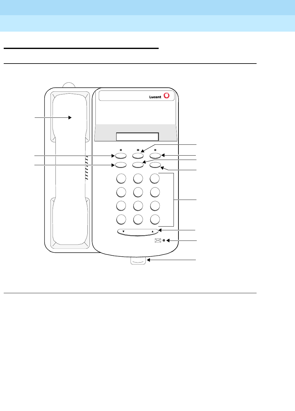
DEFINITYEnterpriseCommunicationsServerandSystem75andSystem85
Terminals and Adjuncts Reference
555-015-201 Issue 11
December 1999
The 6400 Series Telephones
7-2The 6402 and 6402D Telephones
7
The 6402 and 6402D Telephones
Figure 7-1. The 6402 Telephone
7
PQRS
3
DEF
Speaker Feature Hold
Redial Transfer Conf
Test Ring
2
ABC
1
4
GHI
*
56
89
MNOJKL
TUV WXYZ
O#
Volume
Feature button
Hold button
Transfer/Test button
Conference/
Ring button
Dial pad
Volume Control
button
Message Light
Tray handle for
quick reference
cards
Redial
button
Speaker
button
Handset
Tel #
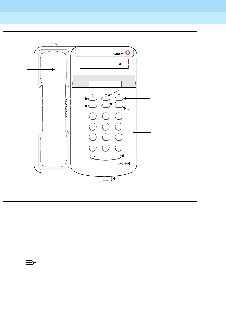
DEFINITYEnterpriseCommunicationsServerandSystem75andSystem85
Terminals and Adjuncts Reference
555-015-201 Issue 11
December 1999
The 6400 Series Telephones
7-3The 6402 and 6402D Telephones
7
Figure 7-2. The 6402D Telephone
The 6402 and 6402D are single-line telephones with six fixed feature buttons: a
listen-only Speaker button, a Feature button that allows you to use the dial pad
keys for up to 12 features assigned by the system manager, a red Hold button, a
Redial button, a Transfer button that can also be used for the Test feature, and a
Conference button that can also be used to select a personalized ringing pattern,
a red Message light, and a Volume control button. The 6402D also has a 2-line by
16-character LCD display.
NOTE:
The 6402 and 6402D can be used ONLY in a 2-wire environment. For more
information, see the section on “Wiring Information.”
7
PQRS
3
DEF
Speaker Feature Hold
Redial Transfer Conf
Test Ring
2
ABC
1
4
GHI
*
56
89
MNOJKL
TUV WXYZ
O#
Volume
2-line by
16-character
display
Feature button
Hold button
Transfer/Test button
Conference/
Ring button
Dial pad
Volume Control
button
Message Light
Tray handle for
quick reference
cards
Redial
button
Speaker
button
Handset
Tel #

DEFINITYEnterpriseCommunicationsServerandSystem75andSystem85
Terminals and Adjuncts Reference
555-015-201 Issue 11
December 1999
The 6400 Series Telephones
7-4The 6402 and 6402D Telephones
7
Applications
The 6402 telephones can best be used with the DEFINITY Enterprise
Communications Server (ECS) Release 6.1 and later. This telephone is especially
suitable for general office workers with low call volumes, manufacturing,
warehousing, guard and/or reception areas, or office desks.
Physical Features
Dimensions
NOTE:
The dimensions described here for the 6402 and 6402D telephones are
approximate.
Width = 7 inches (17.78 cm)
Depth (front to back) = 8.5 inches (21.59 cm)
Height (with deskstand and handset in place) = 4.75 inches (12.07 cm)
Features
Six Fixed Feature Buttons
The 6402 and 6402D telephones have the following six fixed feature buttons:
■SPEAKER button
■FEATURE button
■HOLD button
■REDIAL button
■TRANSFER/TEST button
■CONFERENCE/RING button (labeled CONF)
SPEAKER Button
The 6402 and 6402D telephones are set for the 1-way, listen-only Speaker
feature. The user can only listen to the far-end. However, in order to speak with
the other party, the user must use the handset.
The Feature Button
The FEATURE button allows the dial pad to serve as 12 feature buttons without
indicators. These features are accessed by pressing the FEATURE button and
then one of the 12 dial pad keys.

DEFINITYEnterpriseCommunicationsServerandSystem75andSystem85
Terminals and Adjuncts Reference
555-015-201 Issue 11
December 1999
The 6400 Series Telephones
7-5The 6402 and 6402D Telephones
7
The user has access to a Feature card among the cards in the tray located under
the base of the telephone on which the system manager or the user can write the
features administered on each of the dial pad keys.
HOLD Button
The red HOLD button can be used to put a call on hold. When a call is on hold, the
red light associated with the HOLD button flashes.
REDIAL Button
TheREDIALbuttonisusedtoredialthelastnumbertheuserdialedfromthe
dial pad.
TRANSFER/TEST button
The TRANSFER button can be used in a couple ways: When the telephone is
off-hook, the user can press the TRANSFER button to transfer a call. When the
phone is on-hook, the user can test the lights on the telephone, and if the user has
a 6402D telephone, he or she can use the TRANSFER button to test the display.
(In the latter case, all the display segments fill in.)
CONF/RING Button
The CONFERENCE/RING button can be used in a couple ways: When the
telephone is off-hook, the user can use this button to set up a conference call with
five other people. When the phone is on-hook, the user can press this button to
select a personalized ringing pattern from among eight different patterns.
VOLUME Control button
The 6402 and 6402D telephones have a VOLUME “arrow” button on the front of
the set. This button has several functions. When the user is using the 1-way
speaker, the VOLUME button controls the volume of the speaker. When the user
is on a call using the handset, the VOLUME button controls the volume of the
handset. When the telephone is idle, the button controls the volume of the tone
ringer.
Message Light
The red Message light goes on when a message is left for the user. It goes off
when the user retrieves the message or when the message is erased.

DEFINITYEnterpriseCommunicationsServerandSystem75andSystem85
Terminals and Adjuncts Reference
555-015-201 Issue 11
December 1999
The 6400 Series Telephones
7-6The 6402 and 6402D Telephones
7
Other Physical Features
Pull-out tray
Five quick reference cards are provided in the tray located under the base of every
6400 Series telephone.
Handset
The 6402 and 6402D telephones are equipped with an AJ2A handset.
Dial pad
These telephones are equipped with a 12-button touch-tone dial pad. The letters
“Q” and “Z” have been added to the appropriate dial pad keys for directory access,
and the “5” button on the dial pad has raised bars for visually-impaired users.
Jacks
The 6402 and 6402D telephones’ housing has a Line jack and a Handset cord
jack located on the back of the housing.
Cords
Two cords are supplied with the 6402 and 6402D: a coiled 9-foot handset cord
and a 7-foot line cord.
Optional longer cords are available: a 12-foot handset cord and 14-foot and
25-foot line cords.
Ringing
These telephones have electronic tone ringing. With the Select Ring feature, the
user can choose any one of eight different ringing patterns. The set has a Volume
control button which controls the loudness of the ringer, the speaker, and the
handset.
Mounting Options
The 6402 and 6402D telephones come equipped with a nonadjustable desk
stand. The user can reverse the stand and then mount the telephone on the wall.
Color Options
The 6402 and 6402D telephones are available in gray and in white.
DEFINITYEnterpriseCommunicationsServerandSystem75andSystem85
Terminals and Adjuncts Reference
555-015-201 Issue 11
December 1999
The 6400 Series Telephones
7-7The 6402 and 6402D Telephones
7
Wiring Information
The 6402 and 6402D telephones work in ONLY a 2-wire DCP configuration. The
table below describes the pins on a 6400-Series telephone LINE jack.
Notes on 6400 Series 2-Wire Installation and Wiring:
ALL wiring between the PBX and the telephone wall jack MUST consist of
twisted-pairs. The line cord must be either a D8W, which consists of 4
twisted-pairs, or a D2R which is a 2-conductor non-twisted pair cord. Only these
cord types have been approved by Lucent Technologies. For optimum
performance, the line cord length should not extend beyond that originally
supplied with the telephone.
A D8W modular cord MUST be used for all 2-wire installations requiring auxiliary
power. If using an auxiliary power supply such as a Lucent Technologies 1151A, it
is acceptable to have a D2R cord connected from the wall jack to the LINE jack
found on the power supply.
For 2-wire operation, if you need to plug the telephone into a 4-pin or 6-pin wall
jack, instead of a standard 8-pin modular jack, refer to the “Line Interface” table
above to insure that the wires from the 4-pin or 6-pin wall jack are connected to
the correct pins on the telephone “LINE” jack.
The 6400 Series telephones can be connected to either a RJ45x or an RJ11C
station jack. If connected to an RJ11C, a 2-wire/4-wire Line Adapter must be
installed. This adapter is available to accommodate situations where customers
need to upgrade from an analog type RJ11C jack to an 8-wire RJ45x type jack.
This adapter only works when using a 6400 Series telephone on either the 2-wire
16-port (TN2181) or the 24-port (TN2224) digital line circuit card.
In 2-wire installations using an RJ45x station jack, PBX connections must be on
pins 4 and 5 and auxiliary power must be connected to pins 7 and 8. In 2-wire
installations using an RJ11C station jack, PBX connections must be on pins 3 and
4 and auxiliary power must be connected on pins 2 and 5.
Table 7-1. The Pins on a 6400-Series telephone LINE Jack
Line Interface
Pin Pair Name Description
41 U-T 2-Wire(Tip)
5 1 U-R 2-Wire (Ring)
7 4 P1- Adjunct Power -48V
8 4 P2+ Adjunct Power Common
DEFINITYEnterpriseCommunicationsServerandSystem75andSystem85
Terminals and Adjuncts Reference
555-015-201 Issue 11
December 1999
The 6400 Series Telephones
7-8The 6402 and 6402D Telephones
7
REMOVE ALL CONNECTIONS BETWEEN PAIRS BEFORE CONNECTING THE
TELEPHONE.
Appropriate Circuit Packs and Distance
Limitations
The 6400 Series telephones can only be connected in a 2-wire mode behind the
TN2181 and the TN2224 digital circuit packs.
In 2-wire operation, the telephone must be within 5,500 feet of the PBX using
22-gauge wire, within 3,500 feet of the PBX using 24-gauge wire, and within 2,200
feet of the PBX using 26-gauge wire.
Power Requirements
The 6402 and 6402D telephones receive power from the system and do not
require an external power supply.
Administration
The 6402 telephone can be administered as itself on a DEFINITY system starting
with Release 6.1 software. The 6402D telephone can be administered as itself on
DEFINITY Release 6.3 (or later) system. The 6402 telephone will NOT work with
any DEFINITY switch release prior to the DEFINITY Release 6.1; the 6402D will
NOT work with any DEFINITY switch release prior to the DEFINITY Release 6.3.
NOTE:
When administering the 6402 and 6402D telephones on a DEFINITY switch,
you must select “One-way” or “None” as the speaker option on the
Administration Form.
Button Numbering
The following button diagrams of the 6402 and 6402D telephones will help you
administer the telephones connected to a DEFINITY system.
If you need more information, refer to
DEFINITY Communications System
Generic 3 Implementation
, 555-230-653.
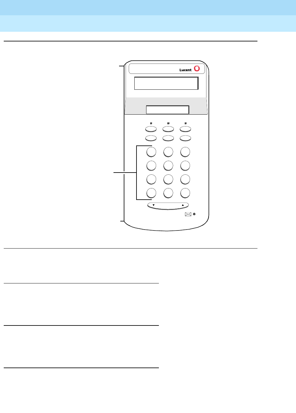
DEFINITYEnterpriseCommunicationsServerandSystem75andSystem85
Terminals and Adjuncts Reference
555-015-201 Issue 11
December 1999
The 6400 Series Telephones
7-9The 6402 and 6402D Telephones
7
Figure 7-3. Button Numbering for Administering the 6402 and 6402D Telephone
Connected to a DEFINITY System Release 6.1 or Later
Power Failure Operation
The 6400 Series telephones cannot be used as an emergency station during
power failure transfer conditions.
FCC Registration
The 6400 Series telephones are FCC-registered along with the switch (as a
system), but do not have a separate FCC registration label.
UL and CSA Approval
The 6400 Series telephones have been tested and have met the Underwriters
Laboratories (UL) Standards UL 1459 and have also met the Canadian Standards
Association (CSA) Standards CSA-C22.2 No.225-M90.
7
PQRS
3
DEF
Speaker Feature Hold
Redial Transfer Conf
Tes t Ring
2
ABC
1
4
GHI
*
56
89
MNOJKL
TUV WXYZ
O#
Volume
Tel #
Administer the features
programmed on the dial pad
as “FEATURE BUTTON
ASSIGNMENTS” 1 through 12.

DEFINITYEnterpriseCommunicationsServerandSystem75andSystem85
Terminals and Adjuncts Reference
555-015-201 Issue 11
December 1999
The 6400 Series Telephones
7-10The 6402 and 6402D Telephones
7
Hearing Aid Compatible
The 6400 Series telephones are compatible with the inductively coupled hearing
aids approved by the FCC.
6402 and 6402D Equipment PECs and Comcodes
The 6402 and 6402D telephones and components can be ordered with these
PECs and Comcodes:
■Basic 6402 (6402D02A) telephone
Gray 6402 Set PEC: 3301-02G
Comcode: 108018284;
White 6402 Set PEC: 3301-02W
Comcode: 108018185
■Basic 6402D (6402D01A) telephone
Gray 6402D Set PEC: 3302-02G
Comcode: 108017989;
White 6402 Set PEC: 3302-02W
Comcode:108017880
■AJ2A Handset
Comcode: Gray=220035018; White=220035000
■Handset cord (9 feet)
Comcode: Gray and White cord comcodes not available at this time
■Line cord (7 feet
PEC: 2725-07G
Comcode: 103786778
■Line cord (14 feet, silver)
PEC: 2725-07N (COL18)
Comcode: 103786828
■Line cord (25 feet, silver)
PEC: 2725-07S (COL18)
Comcode: 103786802
■Designation Card Cover
PEC: 32306
Comcode: 846506780
■Button Designation Cards
Laser Sheet For 25 Sets, 5 Sheets
PEC: 32307
Comcode: 847991718;
Laser Sheet, For 100 Sets, 20 Sheets
PEC: 32308
Comcode: 847167970

DEFINITYEnterpriseCommunicationsServerandSystem75andSystem85
Terminals and Adjuncts Reference
555-015-201 Issue 11
December 1999
The 6400 Series Telephones
7-11The 6402 and 6402D Telephones
7
Adjuncts
The 6400 Series telephones do NOT have an Adjunct jack and therefore will not
support any adjunct equipment.
NOTE:
The Headsets mentioned below are plugged into the Handset jack.
Headsets
A list of compatible headsets, consisting of both modular and plug prong base
units and selection of headpieces, appears in “Headset Adapters” in the Adjuncts
section later in this manual.
Additional Documents
The following documents contain additional information relating to the 6402 and
6402D telephones: (Use the 9 digit number listed after each document to order
that book from the BCS Publications Center for Lucent Technologies.)
■
6400 Series Single-line Telephones User’s Guide
, 555-230-738
■
6400 Series Single-line Telephones Quick Reference Cards,
555-230-751
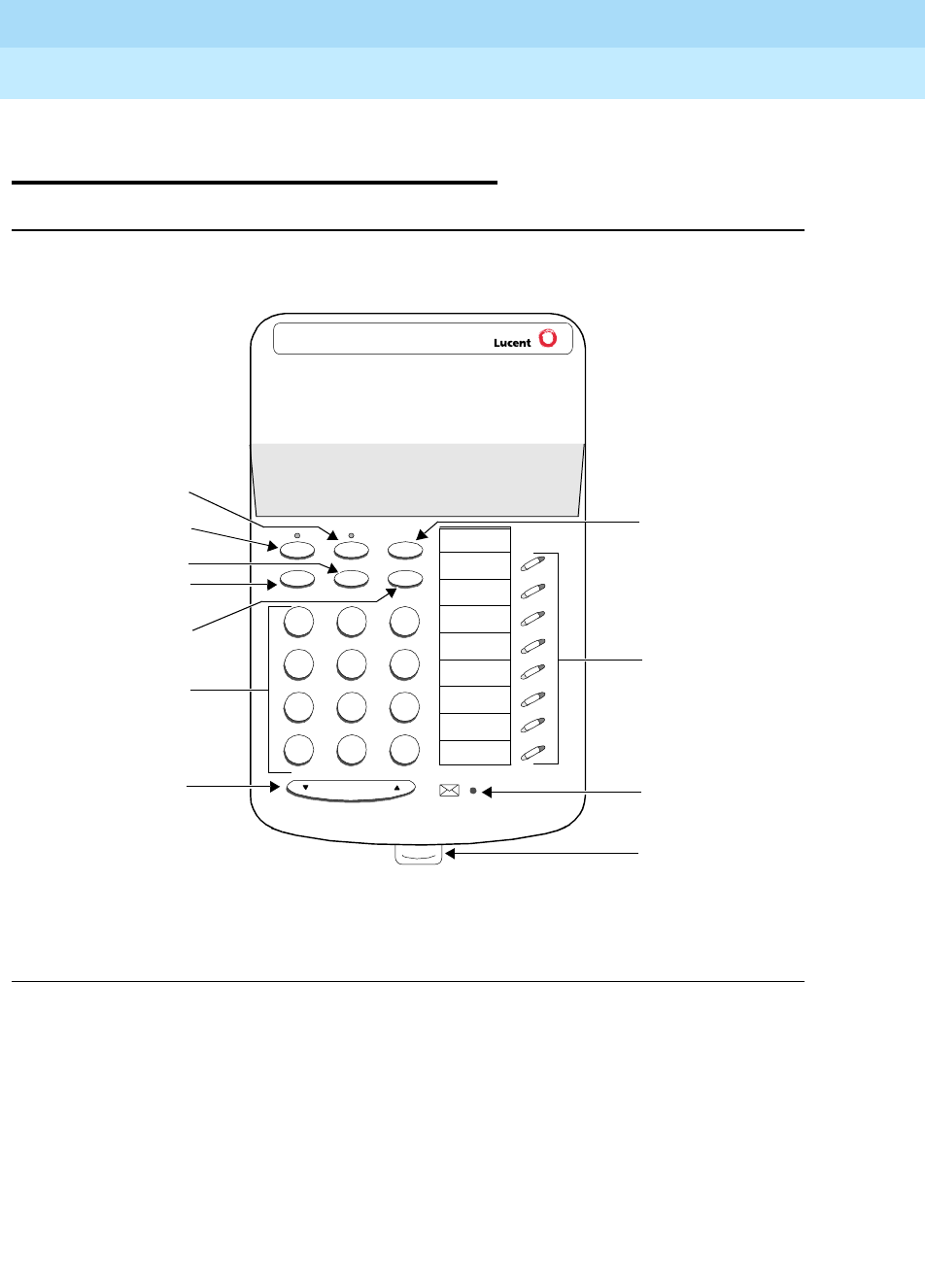
DEFINITYEnterpriseCommunicationsServerandSystem75andSystem85
Terminals and Adjuncts Reference
555-015-201 Issue 11
December 1999
The 6400 Series Telephones
7-12The 6408+ and 6408D+ Telephones
7
The 6408+ and
6408D+ Telephones
Figure 7-4. The 6408+ Telephones
7
PQRS
3
DEF
Speaker Mute Hold
Redial Transfer Conf
Test Ring
2
ABC
1
4
GHI
*
56
89
MNOJKL
TUV WXYZ
O#
Volume
Tel # Hold button
8 call appearance/
feature buttons
Message Light
Tray handle for
quick reference
card
Volume
control
button
Dial pad
Conference/Ring
button
Redial button
Transfer/Test button
Speaker button
Mute button
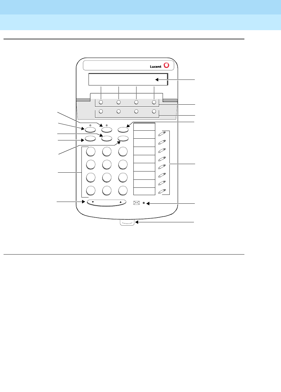
DEFINITYEnterpriseCommunicationsServerandSystem75andSystem85
Terminals and Adjuncts Reference
555-015-201 Issue 11
December 1999
The 6400 Series Telephones
7-13The 6408+ and 6408D+ Telephones
7
Figure 7-5. The 6408D+ Telephone (With Display)
There are two 6408 telephone models: the 6408+ and the 6408D+. Both of these
models are multi-appearance digital telephones with eight call appearance/feature
buttons. The 6408 telephones also have six standard fixed feature buttons:
SPEAKER button, which can access a 2-way speakerphone, MUTE button to
mute the handset or speakerphone microphone, a red HOLD button, REDIAL
button, TRANSFER/TEST button for transferring a call or testing the lights and
display on the telephone, and a CONF/RING button for setting up a conference
call and for selecting a personalized ringing pattern. These telephones also have
a red Message light and a Volume control button.
However, these 6408 models have the following differences:
■The 6408+ has a 2-way speakerphone, without a display.
■The 6408D+ has a 2-way speakerphone and a 2-line by 24-character
display.
7
PQRS
3
DEF
Speaker Mute Hold
Redial Transfer Conf
Test Ring
2
ABC
1
4
GHI
*
56
89
MNOJKL
TUV WXYZ
O#
Volume
Tel #
Menu Exit Prev Next
2-line by
24-character
display
Softkeys
Display control
buttons
Hold button
8 call appearance/
feature buttons
Message Light
Tray handle for
quick reference
card
Volume
control
button
Dial pad
Conference/Ring
button
Redial button
Transfer/Test button
Speaker button
Mute button
DEFINITYEnterpriseCommunicationsServerandSystem75andSystem85
Terminals and Adjuncts Reference
555-015-201 Issue 11
December 1999
The 6400 Series Telephones
7-14The 6408+ and 6408D+ Telephones
7
Those users who have a 6408D+ (the 6408 telephone with display) can access 12
features with the softkeys and display control buttons. These 12 features can be
used
in addition to
the features on the call appearance/feature buttons.
NOTE:
The 6408 telephones can work ONLY in a 2-wire environment. For more
information, see “Wiring Information.”
Applications
Both 6408 telephones have been developed to be used with the DEFINITY ECS
Release 6.1 and later. This type of telephone is especially suitable for managers,
executive secretaries, and other office support personnel who require access to
multiple lines for call handling, call coverage, bridging, conferencing, and
sophisticated voice communications. The 6408D+ display set can be used by
those who have a need for calling party display capabilities or who require a large
number of telephone features.
Physical Features
Dimensions
NOTE:
The dimensions described here for the 6408 telephones are approximate.
Width = 7.8 inches (20 cm)
Depth (front to back) = 8.5 inches (21.59 cm)
Height (with deskstand and handset in place) = 4.75 inches (12.07 cm)
Features
Six Fixed Feature Buttons
The 6408 telephones have the following six fixed feature buttons:
■SPEAKER button
■MUTE button
■HOLD button
■REDIAL button
■TRANSFER/TEST button
■CONFERENCE (labeled CONF)/RING button

DEFINITYEnterpriseCommunicationsServerandSystem75andSystem85
Terminals and Adjuncts Reference
555-015-201 Issue 11
December 1999
The 6400 Series Telephones
7-15The 6408+ and 6408D+ Telephones
7
Speakerphone
The 6408+ and the 6408D+ telephones are equipped with a built-in 2-way
speakerphone. (The telephone can be optioned for a 1-way, listen-only speaker
instead. The system manager should have records of how this feature is
optioned.) The Speakerphone capability allows a user to engage in a hands-free
conversation with the far-end party. The speakerphone can be turned on or off
with the SPEAKER button; can be muted with the MUTE button, and the volume
can be raised and lowered with the VOLUME “arrow” button.
Speaker (Listen-Only) Feature
The 6408+ and the 6408D+ have a two-way speakerphone; however, these two
telephones can be optioned instead for a 1-way, listen-only speaker. If this is the
case, use the SPEAKER button on the front of the telephone for turning on and off
the speaker.
The Speaker (listen-only) capability allows a user to engage in a 1-way
conversation with the far-end. Specifically, the user can only listen to the far-end.
To speak with the far-end, the user must use the handset which turns off the
speaker. The Speaker function may also be disabled.
MUTE Button
The MUTE button is a fixed feature button with a red status light. The MUTE
button turns off the microphone of the built-in speakerphone or the handset so
that a person can converse with another person in the room without the other
party listening in.
HOLD Button
The red HOLD button can be used for putting a call on hold. When a call is on
hold, the green light next to the held call flashes.
REDIAL Button
The REDIAL button can be used for rediaing the last number you dialed from the
dial pad.
TRANSFER/TEST button
The TRANSFER/TEST button can be used in a couple ways: When the telephone
is off-hook, the user can press the TRANSFER button to transfer a call. When the
phone is on-hook, the user can use the TRANSFER button to test the lights and
the display. (In the latter case, all the display segments fill in.)
CONFERENCE/RING Button
The CONFERENCE/RING button can be used in a couple ways: When the
telephone is off-hook, the user can use this button to set up a conference call with
five other people. When the phone is on-hook, the user can press this button to
select a personalized ringing pattern from among eight different patterns.

DEFINITYEnterpriseCommunicationsServerandSystem75andSystem85
Terminals and Adjuncts Reference
555-015-201 Issue 11
December 1999
The 6400 Series Telephones
7-16The 6408+ and 6408D+ Telephones
7
Call Appearance/Feature Buttons
Both 6408 telephones have eight call appearance/feature buttons, each equipped
with a red and a green light. Usually, at least two of these buttons are
administered as call appearances for the telephone’s primary extension number,
where calls are placed and answered. The remainder of the buttons can be used
for more call appearances (including bridged appearances of other stations’
extensions) and features. Buttons administered for features have only their green
status lights active.
Message Light
The red Message light goes on when a message is left for the user. It goes off
when the user retrieves the message or when the message is erased.
VOLUME Control button
The 6408 telephones have a VOLUME “arrow” button on the front of the set. This
button has several functions. When the user is using the speakerphone or the
1-way speaker, the VOLUME button controls the volume of the speaker. When the
user is on a call using the handset, the VOLUME button controls the handset
volume. When the telephone is idle, the button controls the volume of the tone
ringer.
When the user sets the volume for the speaker, speakerphone, handset, or the
tone ringer, the display on the 6408D+ telephones shows a “bar array” that
indicates the volume setting.
Display
The display on the 6408D+ has two lines with 24 characters on each line. The
display, along with the softkeys and the display control buttons, can be used to
access 12 softkey features (the default softkey features and the alternative softkey
features are listed under “Softkeys”).
Display Control Buttons
These four buttons are labeled Menu,Exit,Prev, and Next.
■The Menu button is used to enter Softkey Mode and access the 12 softkey
features.
■The Exit button is used for exiting a display feature and returning to Normal
(call-handling) Mode.
■The Prev and Next buttons can be used to go back and forth through the
feature option screens.
Softkeys
The four buttons located below the display and labeled with arrows correspond to
features listed on the second line of the display screen. (There are four features
on each feature option screen.) The user can access any of the 12 features by
pressing the softkey below the feature abbreviation.
DEFINITYEnterpriseCommunicationsServerandSystem75andSystem85
Terminals and Adjuncts Reference
555-015-201 Issue 11
December 1999
The 6400 Series Telephones
7-17The 6408+ and 6408D+ Telephones
7
Below is a list of the 12 default softkey features assigned to the 6408D+ and the
order in which they appear.
On 6408D+ telephones connected to a DEFINITY system Release 6.1 or later, the
system manager can choose to administer alternate features for use with the
softkeys. The following table lists some of the alternate softkey features that can
be substituted for the default softkey features listed on the previous page.
NOTE:
Future releases of the DEFINITY system may provide additional alternate
softkey features.
NOTE:
The DEFINITY system can download
BLANK
softkey labels for positions
where there are no features administered.
Table 7-2. Default Softkey Features on the 6408D+
Abbreviation Feature
First Screen
Dir* System Directory
Drop Drop
HFAns Internal Auto Answer
Timer Timer
Second Screen
PCall*
* A Call Display button should be administered, if access to System Directory is provided.
Priority Calling
AutCB Automatic Callback
Prog Abbreviated Dialing Program
Pause Abbreviated Dialing Pause
Third Screen
LWC Leave Word Calling
RngOf Ringer Off
BtnVu Button Assignment/View
Admin Self-Administration

DEFINITYEnterpriseCommunicationsServerandSystem75andSystem85
Terminals and Adjuncts Reference
555-015-201 Issue 11
December 1999
The 6400 Series Telephones
7-18The 6408+ and 6408D+ Telephones
7
Table 7-3. Alternate Softkey Features on the 6408D+ Connected to a
DEFINITY ECS Release 6.1 and Later
Abbreviation Feature
Acct Account Code Entry
AD Abbreviated Dialing buttons (can be multiple AD buttons)
CFrwd Call Forwarding All Calls
CPark Call Park
CPkUp Call Pickup
CnLWC Cancel Leave Word Calling
Cnslt Consult
Count ACD Stroke Count
Dpkup Directed Call Pickup
Excl Manual Exclusion
GrpPg Group Paging
IAuto Intercom Auto
IDial Intercom Dial
Inspt Inspect
Mark AD Special Function Mark
Park Call Park to other Extensions
SAC Send All Calls
SFunc Abbreviated Dialed Special Function
Spres Abbreviated Dialing Special Function Suppress
Stats View (ACD) Statistics
Stop Abbreviation Dialing Indefinite Wait or Stop
Wait AD Special Function Wait

DEFINITYEnterpriseCommunicationsServerandSystem75andSystem85
Terminals and Adjuncts Reference
555-015-201 Issue 11
December 1999
The 6400 Series Telephones
7-19The 6408+ and 6408D+ Telephones
7
Other Physical Features
Pull-out tray
Five quick reference cards are provided in the tray located under the base of every
6400 Series telephone.
Handset
Both 6408 telephones are equipped with an AJ2A handset.
Dial pad
Both 6408 telephones have a 12-button touch-tone dial pad. The letters “Q” and
“Z” have been added to the appropriate dial pad keys for directory access, and the
“5” button on the dial pad has raised bars for visually-impaired users.
Jacks
Both 6408 telephones’ housing has a Line jack and a Handset cord jack located
on the back of the housing.
Cords
Two cords are supplied with the 6408: a coiled 9-foot handset cord and a 7-foot
line cord.
Optional longer cords are available: a 12-foot handset cord and 14-foot and
25-foot line cords.
Ringing
Both 6408 telephones have electronic tone ringing with eight possible ringing
patterns which you can select by pressing the CONF button while on-hook. The
loudness of the tone ringer can be controlled by the VOLUME “arrow” button. (The
user must NOT be on a speakerphone call. If the user is using the speakerphone,
the VOLUME “arrow” button controls the volume of the speakerphone.)
Mounting Options
Both 6408 telephones come equipped with a nonadjustable desk stand. The user
can reverse the stand and then mount the telephone on the wall.
Color Options
Both 6408 telephones are available in gray and in white.
DEFINITYEnterpriseCommunicationsServerandSystem75andSystem85
Terminals and Adjuncts Reference
555-015-201 Issue 11
December 1999
The 6400 Series Telephones
7-20The 6408+ and 6408D+ Telephones
7
Wiring Information
Both 6408 telephones work in a 2-wire DCP configuration ONLY. The table below
describes the pins on a 6400-Series telephone LINE jack.
Notes on 6400 Series 2-Wire Installation and Wiring:
ALL wiring between the PBX and the telephone wall jack MUST consist of
twisted-pairs. The line cord must be either a D8W, which consists of 4
twisted-pairs, or a D2R which is a 2-conductor non-twisted pair cord. Only these
cord types have been approved by Lucent Technologies. For optimum
performance, the line cord length should not extend beyond that originally
supplied with the telephone.
A D8W modular cord MUST be used for all 2-wire installations requiring auxiliary
power. If using an auxiliary power supply such as a Lucent Technologies 1151A, it
is acceptable to have a D2R cord connected from the wall jack to the LINE jack
found on the power supply.
For 2-wire operation, if you need to plug the telephone into a 4-pin or 6-pin wall
jack, instead of a standard 8-pin modular jack, refer to the “Line Interface” table
above to insure that the wires from the 4-pin or 6-pin wall jack are connected to
the correct pins on the telephone “LINE” jack.
The 6400 Series telephones can be connected to either a RJ45x or an RJ11C
station jack. If connected to an RJ11C, a 2-wire/4-wire Line Adapter must be
installed. This adapter is available to accommodate situations where customers
need to upgrade from an analog type RJ11C jack to an 8-wire RJ45x type jack.
This adapter only works when using a 6400 Series telephone on either the 2-wire
16-port (TN2181) or the 24-port (TN2224) digital line circuit card.
In 2-wire installations using an RJ45x station jack, PBX connections must be on
pins 4 and 5 and auxiliary power must be connected to pins 7 and 8. In 2-wire
installations using an RJ11C station jack, PBX connections must be on pins 3 and
4 and auxiliary power must be connected on pins 2 and 5.
REMOVE ALL CONNECTIONS BETWEEN PAIRS BEFORE CONNECTING THE
TELEPHONE.
Table 7-4. The Pins on a 6400-Series Telephone LINE Jack
Line Interface
Pin Pair Name Description
41 U-T2-Wire(Tip)
5 1 U-R 2-Wire (Ring)
7 4 P1- Adjunct Power -48V
8 4 P2+ Adjunct Power Common

DEFINITYEnterpriseCommunicationsServerandSystem75andSystem85
Terminals and Adjuncts Reference
555-015-201 Issue 11
December 1999
The 6400 Series Telephones
7-21The 6408+ and 6408D+ Telephones
7
Appropriate Circuit Packs and Distance
Limitations
The 6400 Series telephones can only be connected in a 2-wire mode behind the
TN2181 and the TN2224 digital circuit packs.
In 2-wire operation, the telephone must be within 5,500 feet of the PBX using
22-gauge wire, within 3,500 feet of the PBX using 24-gauge wire, and within 2,200
feet of the PBX using 26-gauge wire.
Power Requirements
Both 6408 telephones receive power from the system and do not require any
external power supply.
Administration
Both 6408 telephones can be administered as themselves on a DEFINITY system
starting with Release 6.1 software. These telephones will NOT work with any
DEFINITY switch release prior to Release 6.1.
Button Numbering
The following button diagrams of the 6408 telephones will help you administer the
telephones connected to a DEFINITY system Release 6.1 or later.
If you need more information, refer to
DEFINITY Communications System
Generic 3 Implementation
, 555-230-653.
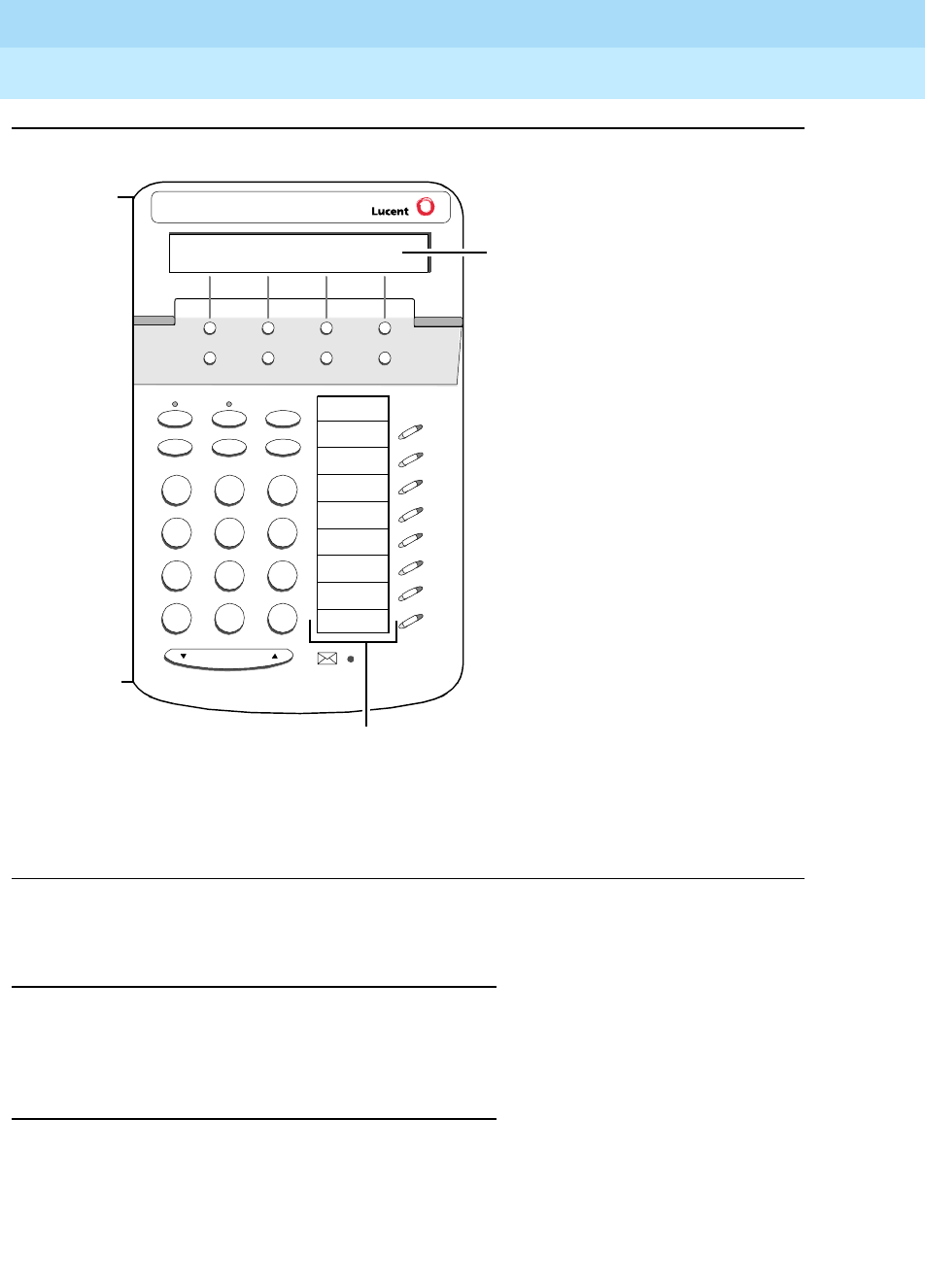
DEFINITYEnterpriseCommunicationsServerandSystem75andSystem85
Terminals and Adjuncts Reference
555-015-201 Issue 11
December 1999
The 6400 Series Telephones
7-22The 6408+ and 6408D+ Telephones
7
Figure 7-6. Button Numbering for Administering the 6408 Telephones Connected to a
DEFINITY System Release 6.1 or Later
Power Failure Operation
The 6400 Series telephones cannot be used as an emergency station during
power failure transfer conditions.
FCC Registration
The 6400 Series telephones are FCC-registered along with the switch (as a
system), but do not have a separate FCC registration label.
7
PQRS
3
DEF
Speaker Mute Hold
Redial Transfer Conf
Test Ring
2
ABC
1
4
GHI
*
56
89
MNO
JKL
TUV WXYZ
O#
Volume
Tel #
Menu Exit Prev Next
The 8 call appearance/
feature buttons are
administered as
“BUTTON ASSIGNMENTS”
1 through 8.
1
2
3
4
5
6
7
8
Administer the 12 softkey
features on “SOFTKEY
BUTTON ASSIGNMENTS”
1 through 12.

DEFINITYEnterpriseCommunicationsServerandSystem75andSystem85
Terminals and Adjuncts Reference
555-015-201 Issue 11
December 1999
The 6400 Series Telephones
7-23The 6408+ and 6408D+ Telephones
7
UL and CSA Approval
The 6400 Series telephones have been tested and have met the Underwriters
Laboratories (UL) Standards UL 1459 and have also met the Canadian Standards
Association (CSA) Standards CSA-C22.2 No.225-M90.
Hearing Aid Compatible
All 6400 Series telephones are compatible with the inductively coupled hearing
aids approved by the FCC.
6408 Telephones and Equipment PECs and
Comcodes
The 6408 telephones and components can be ordered with these PECs and
Comcodes:
■6408+ (6408D02B) telephone (without a display, with two-way
speakerphone)
Gray 6408+ Set PEC: 3303-8BG
Comcode: 108405119;
White 6408+ Set PEC 3303-8BW
Comcode: 108405127
■6408D+ (6408D01B) telephone (with built-in display and two-way
speakerphone)
Gray 6408D+ Set PEC: 3304-8BG
Comcode: 108404849;
White 6408D+ Set PEC: 3304-8BW
Comcode: 108404872
■AJ2A Handset
Comcode: Gray=220035018; White=220035000
■Handset cord (9 feet)
Comcode: Gray and White cord comcodes not available at this time
■Line cord (7 feet)
PEC: 2725-07G
Comcode: 103786778
■Line cord (14 feet, silver)
PEC: 2725-07N (COL18)
Comcode: 103786828
■Line cord (25 feet, silver)
PEC: 2725-07S (COL18)
Comcode: 103786802
■Button Designation Card
Laser Sheet For 25 Sets
PEC: 32310A
DEFINITYEnterpriseCommunicationsServerandSystem75andSystem85
Terminals and Adjuncts Reference
555-015-201 Issue 11
December 1999
The 6400 Series Telephones
7-24The 6408+ and 6408D+ Telephones
7
Comcode: 847770666;
Laser Sheet For 100 Sets
PEC: 32311A
Comcode: 847770674
Adjuncts
The 6408 telephones do NOT have an Adjunct jack on the bottom of the
telephone. Therefore, adjunct equipment cannot be used with these telephones.
NOTE:
The Headsets mentioned below are plugged into the Handset jack.
Headsets
A list of compatible headsets, consisting of both modular and plug prong base
units and selection of headpieces, appears in “Headset Adapters” in the Adjuncts
section later in this manual.
Additional Documents
The following documents contain additional information relating to the 6408
telephones: (Use the 9 digit number listed after each document to order that book
from the BCS Publications Center for Lucent Technologies.)
■
6408+, 6408D+, 6416D+, and 6424D+ Telephones User’s Guide
,
555-230-739
■
6400 Series Multi-line Quick Reference Cards
, 555-104-752
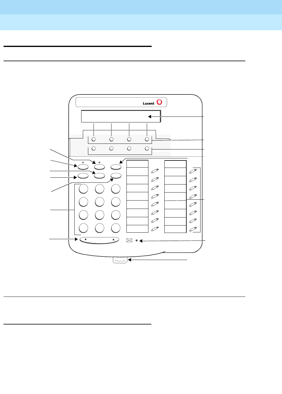
DEFINITYEnterpriseCommunicationsServerandSystem75andSystem85
Terminals and Adjuncts Reference
555-015-201 Issue 11
December 1999
The 6400 Series Telephones
7-25The 6416D+ and 6416D+M Telephones
7
The 6416D+ and 6416D+M Telephones
Figure 7-7. The 6416D+ and 6416D+M Telephone
All 6416D+ and 6416D+M Telephones
The 6416D+ and 6416D+M telephones are multi-appearance digital telephones
with 16 call appearance/feature buttons. These telephones also have six standard
fixed feature buttons: a SPEAKER button, which can access a 2-way
speakerphone, MUTE button to mute the handset or speakerphone microphone, a
red HOLD button, REDIAL button, TRANSFER/TEST button for transferring a call
or testing the lights and display on the telephone, and a CONF/RING button for
setting up a conference call and for selecting a personalized ringing pattern.
These telephones also have a red Message light and a Volume control button.
7
PQRS
3
DEF
Speaker Mute Hold
Redial Transfer Conf
Test Ring
2
ABC
1
4
GHI
*
56
89
MNOJKL
TUV WXYZ
O#
Volume
Tel #
Menu Exit Prev Next
Display
Softkeys
Display control
Hold button
16 Call appearance/
feature buttons
Message light
Tray handle
Mute button
Speaker button
Redial button
Transfer/Test button
Conference/Ring
button
Dial pad
Volume control
button
Tel #
buttons
DEFINITYEnterpriseCommunicationsServerandSystem75andSystem85
Terminals and Adjuncts Reference
555-015-201 Issue 11
December 1999
The 6400 Series Telephones
7-26The 6416D+ and 6416D+M Telephones
7
With the 6416D+ and 6416D+M telephones you can access 12 features with the
softkeys and display control buttons. These 12 features can be used
in addition to
the features on the call appearance/feature buttons.
NOTE:
The 6416D+ and 6416D+M telephones can work ONLY in a 2-wire
environment. For more information, see “Wiring Information.”
An XM24 expansion module can be connected to any 6416D+ and 6416D+M
telephone to expand the number of buttons you can use. However, when the
expansion module is connected, you must connect an auxiliary power supply to
the telephone. An 1151A1 local power supply or an 1151A2 local power supply
with Battery Holdover is recommended.
Only the Modular 6416D+M Telephone
In June, 1999, Modular 6416D+M (the 6416D02A) and 6424D+ (the 6424D02A)
telephones will also be available. These modular telephones allow you to install a
100A Tip/Ring module in the desktop stand on the telephone for increased set
functionality. Through a 6-position RJ11-type jack, the Tip/Ring module provides
connection between these two 6400 Series telephone models and such analog
adjuncts as answering machines, fax machines, modems, analog speakerphones,
and TDD machines commonly used by the hearing impaired.
NOTE:
Only the 6416D+M and 6424D+M models have modular capabilities; that is,
the regular non-modular 6416D+M and 6424D+M models do NOT have
these capabilities.
NOTE:
In order for the Modular 6416D+M and 6424D+M sets to operate, you must
connect an auxiliary power supply to the telephone.
For more information about the 100A Tip/Ring Module, refer to “The 100A
Tip/Ring Module” in the Adjuncts section later in this manual.
Applications
All 6416D+ and 6424D+M Telephones
The 6416D+and 6416D+M telephones can be used with the DEFINITY ECS
Release 6.1 and later. These telephones are especially suitable for managers,
executive secretaries, and other office support personnel who require access to
multiple lines for call handling, call coverage, bridging, conferencing, and
sophisticated voice communications. The display on these sets can be used by
those who have a need for calling party display capabilities or who require a large
number of telephone features.

DEFINITYEnterpriseCommunicationsServerandSystem75andSystem85
Terminals and Adjuncts Reference
555-015-201 Issue 11
December 1999
The 6400 Series Telephones
7-27The 6416D+ and 6416D+M Telephones
7
Applications for the Modular 6416D+M
Telephone Only
If the Modular 6416D+M telephone is being used with a DEFINITY switch, the
manner in which the telephone and the analog adjunct interact depends on the
switch release to which your telephone is connected. (Your system manager can
give you more information about the switch release.)
■On DEFINITY releases prior to Release 8.1, going back to Release 6.1, the
analog adjunct shares the telephone line with the telephone. Therefore,
while the telephone is being used, you
cannot
use the analog adjunct at the
same time, or vice versa.
■On the DEFINITY Release 8.1 and later, the telephone and the analog
adjunct can be assigned separate telephone lines, and thus the telephone
and analog adjunct can be used
simultaneously
.
Physical Features
Dimensions
NOTE:
The dimensions described here for the 6416D+ and 6416D+M telephones
are approximate.
Width = 10.35 inches (26.35 cm)
Depth (front to back) = 8.5 inches (21.59 cm)
Height (with deskstand and handset in place) = 4.75 inches (12.07 cm)
Features
Six Fixed Feature Buttons
The 6416D+ and 6416D+M telephones have the following six fixed feature
buttons:
■SPEAKER button
■MUTE button
■HOLD button
■REDIAL button
■TRANSFER/TEST button
■CONFERENCE (labeled CONF)/RING button

DEFINITYEnterpriseCommunicationsServerandSystem75andSystem85
Terminals and Adjuncts Reference
555-015-201 Issue 11
December 1999
The 6400 Series Telephones
7-28The 6416D+ and 6416D+M Telephones
7
Speaker (Listen-Only) Feature
The 6416D+ and 6416D+M telephones have a two-way speakerphone; however,
the telephones can also be optioned instead for a 1-way, listen-only speaker. If
this is the case, use the SPEAKER button on the front of the telephone for turning
on and off the speaker.
The Speaker (listen-only) capability allows a user to engage in a 1-way
conversation with the far-end. Specifically, the user can only listen to the far-end.
To speak with the far-end, the user must use the handset which turns off the
speaker. The Speaker function may also be disabled.
Speakerphone
The 6416D+ and 6416D+M telephones are equipped with a built-in 2-way
speakerphone. (The telephone can be optioned for a 1-way, listen-only speaker
instead. The system manager should have records of how this feature is
optioned.) The Speakerphone capability allows a user to engage in a hands-free
conversation with the far-end party. The speakerphone can be turned on or off
with the SPEAKER button; can be muted with the MUTE button, and the volume
can be raised and lowered with the VOLUME “arrow” button.
MUTE Button
The MUTE button is a fixed feature button with a red status light. The MUTE
button turns off the microphone of the built-in speakerphone or the handset so
that a person can converse with another person in the room without the other
party listening in.
HOLD Button
The red HOLD button can be used for putting a call on hold. When a call is on
hold, the green light next to the held call flashes.
REDIAL Button
The REDIAL button can be used for rediaing the last number you dialed from the
dial pad.
TRANSFER/TEST button
The TRANSFER/TEST button can be used in a couple ways: When the telephone
is off-hook, the user can press the TRANSFER button to transfer a call. When the
phone is on-hook, the user can use the TRANSFER button to test the lights and
the display. (In the latter case, all the display segments fill in.)
CONFERENCE/RING Button
The CONFERENCE/RING button can be used in a couple ways: When the
telephone is off-hook, the user can use this button to set up a conference call with
five other people. When the phone is on-hook, the user can press this button to
select a personalized ringing pattern from among eight different patterns.

DEFINITYEnterpriseCommunicationsServerandSystem75andSystem85
Terminals and Adjuncts Reference
555-015-201 Issue 11
December 1999
The 6400 Series Telephones
7-29The 6416D+ and 6416D+M Telephones
7
Call Appearance/Feature Buttons
The 6416D+ and 6416D+M telephones have 16 call appearance/feature buttons,
each equipped with a red and a green light. Usually, at least two of these buttons
are administered as call appearances for the telephone’s primary extension
number, where calls are placed and answered. The remainder of the buttons can
be used for more call appearances (including bridged appearances of other
stations’ extensions) and features. Buttons administered for features have only
their green status lights active.
Message Light
The red Message light goes on when a message is left for the user. It goes off
when the user retrieves the message or when the message is erased.
VOLUME Control button
The 6416D+ and 6416D+M telephones have a VOLUME “arrow” button on the
front of the set. This button has several functions. When the user is using the
speakerphone or the 1-way speaker, the VOLUME button controls the volume of
the speaker. When the user is on a call using the handset, the VOLUME button
controls the handset volume. When the telephone is idle, the button controls the
volume of the tone ringer.
When the user sets the volume for the speaker, speakerphone, handset, or the
tone ringer, the display on the 6416D+ telephone shows a “bar array” that
indicates the volume setting.
Display
The display on the 6416D+ and 6416D+M telephones has two lines with
24 characters on each line. The display, along with the softkeys and the display
control buttons, can be used to access 12 softkey features. (The default softkey
features and the alternative softkey features are listed under “Softkeys.”)
Display Control Buttons
These four buttons are labeled Menu,Exit,Prev, and Next.
■The Menu button is used to enter Softkey Mode and access the 12 softkey
features.
■The Exit button is used for exiting a display feature and returning to Normal
(call-handling) Mode.
■The Prev and Next buttons can be used to go back and forth through the
feature option screens.
Softkeys
The four buttons located below the display and labeled with arrows correspond to
features listed on the second line of the display screen. (There are four features
on each feature option screen.) The user can access any of the 12 features by
pressing the softkey below the feature abbreviation.
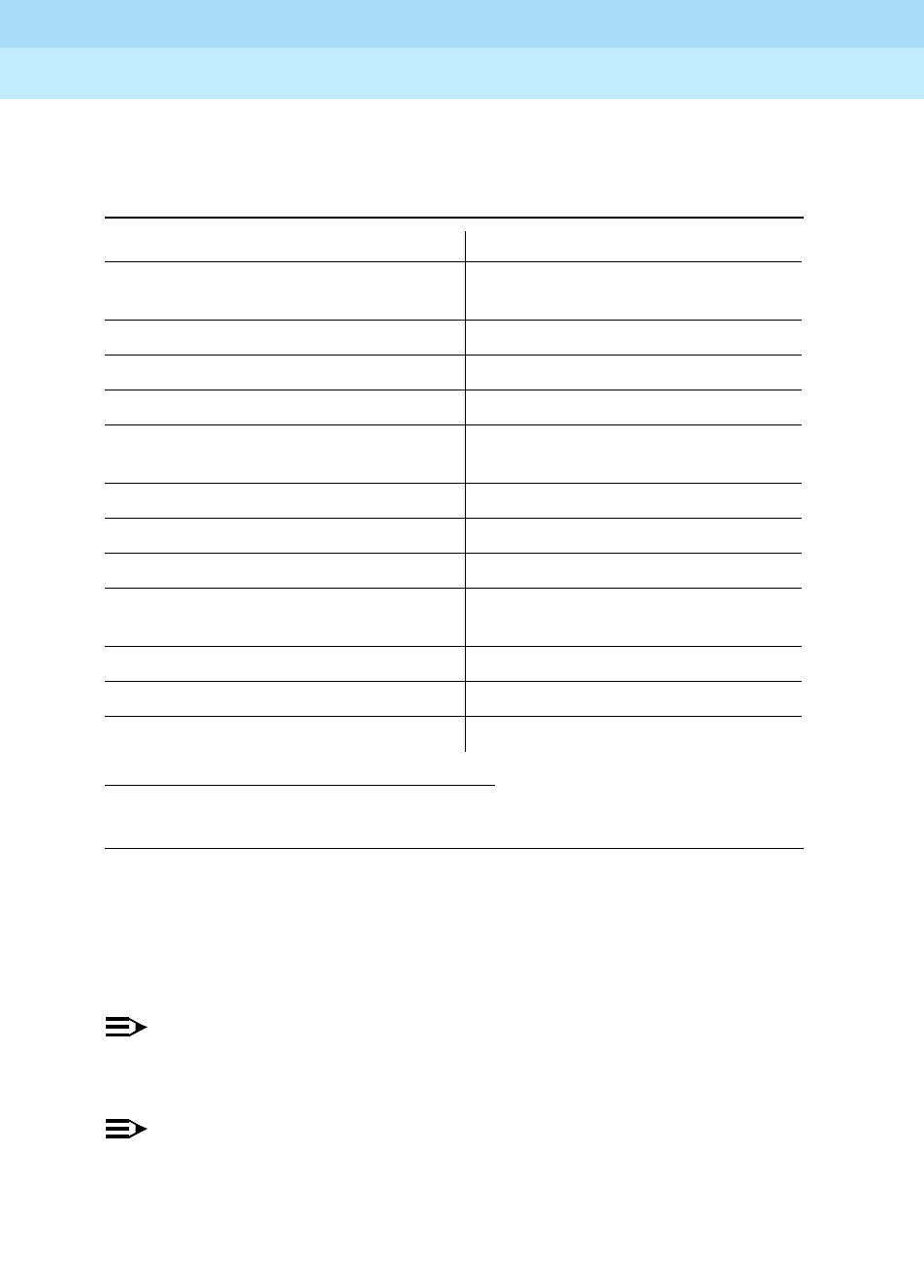
DEFINITYEnterpriseCommunicationsServerandSystem75andSystem85
Terminals and Adjuncts Reference
555-015-201 Issue 11
December 1999
The 6400 Series Telephones
7-30The 6416D+ and 6416D+M Telephones
7
Below is a list of the 12 default softkey features assigned to the 6416D+ and
6416D+M telephones and the order in which they appear.
On 6416D+ and 6416D+M telephones connected to a DEFINITY ECS
Release 6.1 or later, the system manager can choose to administer alternate
features for use with the softkeys. The following table lists some of the alternate
softkey features that can be substituted for the default softkey features listed on
the previous page.
NOTE:
Future releases of the DEFINITY system may provide additional alternate
softkey features.
NOTE:
The DEFINITY system can download
BLANK
softkey labels for positions
where there are no features administered.
Table 7-5. Default Softkey Features on the 6416D+ and 6416D+M
Abbreviation Feature
First Screen
Dir* System Directory
Drop Drop
HFAns Internal Auto Answer
Timer Timer
Second Screen
PCall*
* A Call Display button should be administered, if access to System Directory is provided.
Priority Calling
AutCB Automatic Callback
Prog Abbreviated Dialing Program
Pause Abbreviated Dialing Pause
Third Screen
LWC Leave Word Calling
RngOf Ringer Off
BtnVu Button Assignment/View
Admin Self-Administration

DEFINITYEnterpriseCommunicationsServerandSystem75andSystem85
Terminals and Adjuncts Reference
555-015-201 Issue 11
December 1999
The 6400 Series Telephones
7-31The 6416D+ and 6416D+M Telephones
7
Table 7-6. Alternate Softkey Features on the 6416D+ and 6416D+M Connected
to a DEFINITY ECS Release 6.1 and Later
Abbreviation Feature
Acct Account Code Entry
AD Abbreviated Dialing buttons (can be multiple AD buttons)
CFrwd Call Forwarding All Calls
CPark Call Park
CPkUp Call Pickup
CnLWC Cancel Leave Word Calling
Cnslt Consult
Count ACD Stroke Count
Dpkup Directed Call Pickup
Excl Manual Exclusion
GrpPg Group Paging
IAuto Intercom Auto
IDial Intercom Dial
Inspt Inspect
Mark AD Special Function Mark
Park Call Park to other Extensions
SAC Send All Calls
SFunc Abbreviated Dialed Special Function
Spres Abbreviated Dialing Special Function Suppress
Stats View (ACD) Statistics
Stop Abbreviation Dialing Indefinite Wait or Stop
Wait AD Special Function Wait

DEFINITYEnterpriseCommunicationsServerandSystem75andSystem85
Terminals and Adjuncts Reference
555-015-201 Issue 11
December 1999
The 6400 Series Telephones
7-32The 6416D+ and 6416D+M Telephones
7
Other Physical Features
Pull-out tray
Five quick reference cards are provided in the tray located under the base of every
6400 Series telephone.
Handset
The 6416D+ and 6416D+M telephones are equipped with an AJ2A handset which
can accept either a handset or a headset.
Dial pad
The 6416D+ and 6416D+M telephones are equipped with a 12-button touch-tone
dial pad. The letters “Q” and “Z” have been added to the appropriate dial pad keys
for directory access, and the “5” button on the dial pad has raised bars for
visually-impaired users.
Jacks
The housing of the 6416D+ and 6416D+M telephones has a Line jack and a
Handset cord jack located on the back of the housing. These telephones also
have an Expansion Module (“XM24”) jack on the back of the telephone to allow
connection of an XM24 expansion module.
In addition, the Modular 6416D+M telephones have a Headset jack on the back of
the telephone. The Handset cord jack can be used for either a headset or a
handset; however, the Headset jack can be used only with a headset.
NOTE:
When a modular base unit is used with the Headset jack, the handset
should remain plugged into the Handset jack.
NOTE:
If you plug the headset directly into the Headset jack, you may use a button
on the adapter cord, if so equipped, to go off-hook and on-hook, or a
button may be administered.
Cords
Two cords are supplied with the 6416D+ and 6416D+M telephones: a coiled 9-foot
handset cord and a 7-foot line cord.
Optional longer cords are available: a 12-foot handset cord and 14-foot and
25-foot line cords.
In order for the tip/ring module to operate with the Modular 6416D+M telephone,
the telephone’s desktop stand and the required auxiliary power supply must be
connected with an 8-foot D8W cord.
Headset On/Off

DEFINITYEnterpriseCommunicationsServerandSystem75andSystem85
Terminals and Adjuncts Reference
555-015-201 Issue 11
December 1999
The 6400 Series Telephones
7-33The 6416D+ and 6416D+M Telephones
7
Ringing
The 6416D+ and 6416D+M telephones have electronic tone ringing with eight
possible ringing patterns which you can select by pressing the CONF button while
on-hook. The loudness of the tone ringer can be controlled by the VOLUME
“arrow” button. (The user must NOT be on a speakerphone call. If the user is
using the speakerphone, the VOLUME “arrow” button controls the volume of the
speakerphone.)
Mounting Options
The 6416D+ and 6416D+M telephones come equipped with a nonadjustable desk
stand. The user of the 6416D+ can reverse the stand and then mount the
telephone on the wall.
However, if there is a module connected in the Modular 6416D+M telephone’s
desktop stand, the telephone can ONLY be desk mounted: it CANNOT be
wall-mounted.
Color Options
The 6416D+ and 6416D+M telephones are available in gray and in white.
Wiring Information
The 6416D+ and 6416D+M telephones work in a 2-wire DCP configuration ONLY.
The table below describes the pins on a 6400-Series telephone LINE jack.
Notes on 6400 Series 2-Wire Installation and Wiring:
ALL wiring between the PBX and the telephone wall jack MUST consist of
twisted-pairs. The line cord must be either a D8W, which consists of 4
twisted-pairs, or a D2R which is a 2-conductor non-twisted pair cord. Only these
cord types have been approved by Lucent Technologies. For optimum
performance, the line cord length should not extend beyond that originally
supplied with the telephone.
Table 7-7. The Pins on a 6400-Series Telephone LINE Jack
Line Interface
Pin Pair Name Description
41 U-T2-Wire(Tip)
5 1 U-R 2-Wire (Ring)
7 4 P1- Adjunct Power -48V
8 4 P2+ Adjunct Power Common

DEFINITYEnterpriseCommunicationsServerandSystem75andSystem85
Terminals and Adjuncts Reference
555-015-201 Issue 11
December 1999
The 6400 Series Telephones
7-34The 6416D+ and 6416D+M Telephones
7
A D8W modular cord MUST be used for all 2-wire installations requiring auxiliary
power. If using an auxiliary power supply such as a Lucent Technologies 1151A, it
is acceptable to have a D2R cord connected from the wall jack to the LINE jack
found on the power supply.
For 2-wire operation, if you need to plug the telephone into a 4-pin or 6-pin wall
jack, instead of a standard 8-pin modular jack, refer to the “Line Interface” table
above to insure that the wires from the 4-pin or 6-pin wall jack are connected to
the correct pins on the telephone “LINE” jack.
The 6400 Series telephones can be connected to either a RJ45x or an RJ11C
station jack. If connected to an RJ11C, a 2-wire/4-wire Line Adapter must be
installed. This adapter is available to accommodate situations where customers
need to upgrade from an analog type RJ11C jack to an 8-wire RJ45x type jack.
This adapter only works when using a 6400 Series telephone on either the 2-wire
16-port (TN2181) or the 24-port (TN2224) digital line circuit card.
In 2-wire installations using an RJ45x station jack, PBX connections must be on
pins 4 and 5 and auxiliary power must be connected to pins 7 and 8. In 2-wire
installations using an RJ11C station jack, PBX connections must be on pins 3 and
4 and auxiliary power must be connected on pins 2 and 5.
REMOVE ALL CONNECTIONS BETWEEN PAIRS BEFORE CONNECTING THE
TELEPHONE.
Appropriate Circuit Packs and Distance
Limitations
The 6400 Series telephones can only be connected in a 2-wire mode behind the
TN2181 and the TN2224 digital circuit packs. For more information see “Wiring
Information” above.
In 2-wire operation, the telephone must be within 5,500 feet of the PBX using
22-gauge wire, within 3,500 feet of the PBX using 24-gauge wire, and within 2,200
feet of the PBX using 26-gauge wire.
Power Requirements
The regular (non-modular) 6416D+ telephone receives power from the system
and does not require any external power supply. However, if the 6416D+ is
connected to an XM24 Expansion Module or if you are using a Modular 6416D+M,
there MUST be auxiliary power in the form of a local power supply such as an
1151A1 or an 1151A2 with Battery Holdover, or a bulk power supply such as an
1145A or 1145B1.
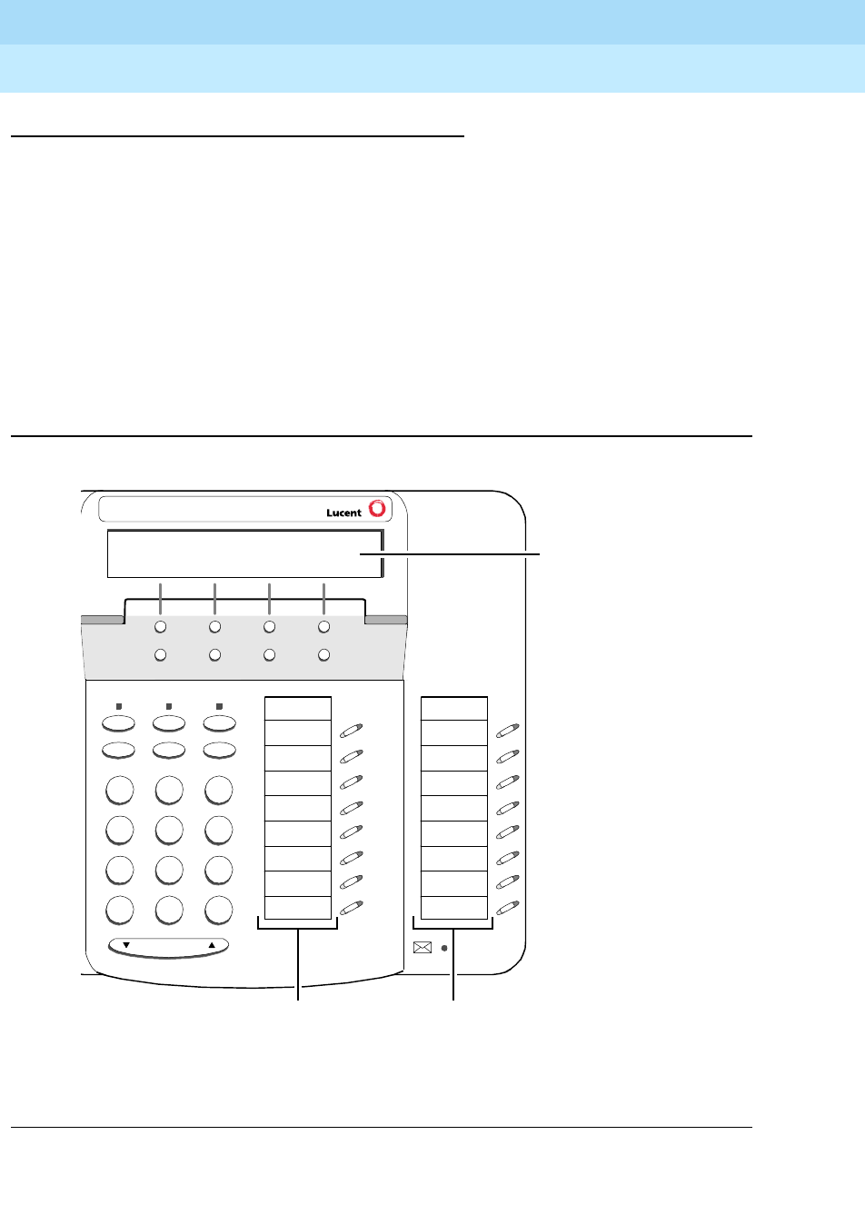
DEFINITYEnterpriseCommunicationsServerandSystem75andSystem85
Terminals and Adjuncts Reference
555-015-201 Issue 11
December 1999
The 6400 Series Telephones
7-35The 6416D+ and 6416D+M Telephones
7
Administration
The 6416D+ and 6416D+M telephones can be administered as themselves on a
DEFINITY system starting with Release 6.1 software. These telephones will NOT
work with any DEFINITY switch release prior to Release 6.1.
Button Numbering
The following button diagrams of the 6416D+ and 6416D+M telephone will help
you administer these telephones connected to a DEFINITY ECS Release 6.1 or
later.
If you need more information, refer to
DEFINITY Communications System
Generic 3 Implementation
, 555-230-653.
Figure 7-8. Button Numbering for Administering the 6416D+ or 6416D+M Telephone
Connected to a DEFINITY System Release 6.1 or Later
7
PQRS
3
DEF
Speaker Mute Hold
Redial Transfer Conf
Test Ring
2
ABC
1
4
GHI
*
56
89
MNOJKL
TUV WXYZ
O#
Volume
Menu Exit Prev Next
Tel #
1
2
3
4
5
6
7
8
9
10
11
12
13
14
15
16
Administer the first
column of 8 call appearance/
features buttons as “BUTTON
ASSIGNMENTS” 1 - 8.
Administer the second column
as “FEATURE BUTTON
ASSIGNMENTS” 9 - 16.
Administer the 12 softkey
features on “SOFTKEY
BUTTON ASSIGNMENTS”
1 through 12.

DEFINITYEnterpriseCommunicationsServerandSystem75andSystem85
Terminals and Adjuncts Reference
555-015-201 Issue 11
December 1999
The 6400 Series Telephones
7-36The 6416D+ and 6416D+M Telephones
7
Administering the Analog Adjunct on the
Modular 6416D+M Telephone
As noted above, all 6416D+ and 6416D+M can be administered as themselves
ONLY IF they are connected to a DEFINITY ECS Release 6.1 (or later). In Native
Mode the Modular 6416D+M telephone is administered through a digital line
circuit card with a line number (with the usual three call appearances) assigned to
the I-1 Channel. If the Modular 6416D+M is connected to a DEFINITY ECS
Release 8.1 or later, a second line number can be administered through the same
digital line card on the I-2 Channel, but this line number can only be used for
analog adjuncts connected to the Tip/Ring module. This analog adjunct is
assigned a private number, but can be used only for placing or terminating a call.
It cannot be used for any other analog functions such as transferring a call or
setting up a conference call. If a second line on the telephone is administered on
the I-2-Channel (for analog equipment), type “analog” in the Data Option field on
the administration screen.
Power Failure Operation
The 6416D+ and 6416D+M telephones cannot be used as an emergency station
during power failure transfer conditions.
FCC Registration
The 6400 Series telephones are FCC-registered along with the switch (as a
system), but do not have a separate FCC registration label.
UL and CSA Approval
The 6400 Series telephones have been tested and have met the Underwriters
Laboratories (UL) Standards UL 1459 and have also met the Canadian Standards
Association (CSA) Standards CSA-C22.2 No.225-M90.
Hearing Aid Compatible
All 6400 Series telephones are compatible with the inductively coupled hearing
aids approved by the FCC.

DEFINITYEnterpriseCommunicationsServerandSystem75andSystem85
Terminals and Adjuncts Reference
555-015-201 Issue 11
December 1999
The 6400 Series Telephones
7-37The 6416D+ and 6416D+M Telephones
7
6416D+ and 6416D+M Telephones and
Equipment PECs and Comcodes
The 6416D+ and 6416D+M telephones and components can be ordered with
these PECs and Comcodes:
■6416D+ (6416D01A) telephone
Gray 6416D+ Set PEC: 3306-16G
Comcode: 108019951;
White 6416D Set PEC: 3306-16W
Comcode: 108019845
■Modular Class B 6416D+M (6416D02A) telephone
Gray 6416D+M Set PEC: 3306-6MG
Comcode: 108020256;
White 6416D+M Set PEC: 3306-6MW
Comcode: 108020157
■AJ2A Handset
Comcode: Gray=220035018; White=220035000
■Handset cord (9 feet)
Comcode: Gray and White cord comcodes not available at this time
■D8W-87 Line cord (7 feet)
PEC: 2725-07G
Comcode: 103786778
■D8W-87 Line cord (14 feet, silver)
PEC: 2725-07N (COL18)
Comcode: 103786828
■D8W-87 Line cord (25 feet, silver)
PEC: 2725-07S (COL18)
Comcode: 103786802
■D2R-87 Line cord (14 feet)
Comcode: 105001861
■Button Designation Card
Laser Sheet For 25 Sets
PEC: 32310A
Comcode: 847770666;
Laser Sheet For 100 Sets
PEC: 32311A
Comcode: 847770674
■100A-266 Tip/Ring Module (White)
PEC: 3305-TR1
Comcode: 108332446
100A-266Tip/Ring Module with 1151A Power Supply
PEC: 3305-TRP

DEFINITYEnterpriseCommunicationsServerandSystem75andSystem85
Terminals and Adjuncts Reference
555-015-201 Issue 11
December 1999
The 6400 Series Telephones
7-38The 6416D+ and 6416D+M Telephones
7
■XM24 Expansion Module (for the non-modular 6416D+ and 6424D+)
Gray XM24 = PEC: 33076/A, Comcode: 108023243
White XM24 = PEC: 33074/A, Comcode: 108023235
■XM24 Expansion Module (with a new base angle for the 6416D+M,
6424D+M, and CALLMASTER V)
Gray XM24 = PEC: 33071/A, Comcode: 108544511
White XM24 = PEC: 33072/A, Comcode: 108554503
Adjuncts
The Modular 6416D+M telephones, with the connected 100A Tip/Ring module in
the desktop stand, allow connection with such analog adjuncts as answering
machines, fax machines, modems, analog speakerphones, and TDD machines
commonly used by the hearing impaired. For more information about these
connections with the 100A Tip/Ring module, see the Adjuncts section later in this
manual.
The non-Modular 6416D+ telephones
cannot
accommodate any adjunct
equipment.
NOTE:
The Headsets mentioned below can be plugged into the Handset jack. On
the Modular 6416D+M, there is also a Headset jack to which a headset can
be connected.
Headsets
A list of compatible headsets, consisting of both modular and plug prong base
units and selection of headpieces, appears in “Headset Adapters” in the Adjuncts
section later in this manual.
Additional Documents
The following documents contain additional information relating to the 6416D+
and 6416D+M telephone: (Use the 9 digit number listed after each document to
order that book from the BCS Publications Center for Lucent Technologies.)
■
6408+, 6408D+, 6416D+, 6416D+M, 6424D+, and 6424D+M Telephones
User’s Guide
, 555-230-739
■
6400 Series Multi-line Telephones Quick Reference Cards
, 555-104-752
■
The Tip/Ring Interface Module Installation and User Instructions,
555-233-707.
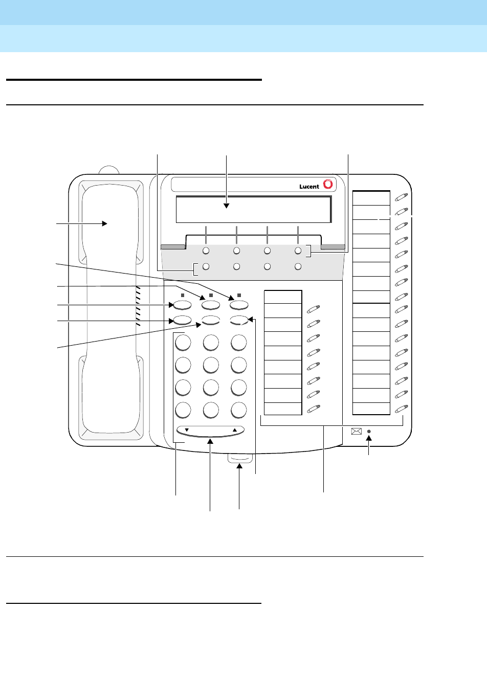
DEFINITYEnterpriseCommunicationsServerandSystem75andSystem85
Terminals and Adjuncts Reference
555-015-201 Issue 11
December 1999
The 6400 Series Telephones
7-39The 6424D+ and 6424D+M Telephone
7
The 6424D+ and 6424D+M Telephone
Figure 7-9. The 6424D+ and 6424D+M Telephone
All 6424D+ and 6424D+M Telephones
The 6424D+ and 6424D+M telephones are multi-appearance digital telephones
with 24 call appearance/feature buttons. The telephones also have six standard
fixed feature buttons: a SPEAKER button, which can access a 2-way
speakerphone, a MUTE button to mute the handset or speakerphone microphone,
7
PQRS
3
DEF
Speaker Mute Hold
Redial Transfer Conf
Test Ring
2
ABC
1
4
GHI
*
56
89
MNOJKL
TUV WXYZ
O#
Volume
Mute
Hold
Transfer/
Conference/
Ring button
Dial pad
Message
Tray handle for
quick reference
cards
Redial
button
Handset
Menu Exit Prev Next
Display 2-line by
24-character
display Softkeys
24 call appearance/
feature buttons
Light
Speaker
button
button
button
button
Test
Volume
buttons
control
button
Control
Tel #

DEFINITYEnterpriseCommunicationsServerandSystem75andSystem85
Terminals and Adjuncts Reference
555-015-201 Issue 11
December 1999
The 6400 Series Telephones
7-40The 6424D+ and 6424D+M Telephone
7
a red HOLD button, REDIAL button, TRANSFER/TEST button for transferring a
call or testing the lights and display on the telephone, and a CONF/RING button
for setting up a conference call and for selecting a personalized ringing pattern.
These telephones also have a red Message light and a Volume control button.
With the 6424D+ and 6424D+M telephones you can access 12 features with the
softkeys and display control buttons. These 12 features can be used
in addition to
the features on the call appearance/feature buttons.
NOTE:
The 6424D+ and 6424D+M telephones can work ONLY in a 2-wire
environment. For more information, see “Wiring Information.”
An XM24 expansion module can be connected to any 6424D+ or 6424D+M
telephone to expand the number of buttons you can use. However, when the
expansion module is connected, you must connect an auxiliary power supply to
the telephone. An 1151A1 local power supply or an 1151A2 local power supply
with Battery Holdover are recommended.
Only the Modular 6424D+M
In June, 1999, Modular 6416D+M (6416D02A) and 6424D+M (6424D02A)
telephones will also be available. These modular telephones allow you to install a
100A Tip/Ring module in the desktop stand on the telephone for increased set
functionality. Through a 6-position RJ11-type jack, the Tip/Ring module provides
connection between these two 6400 Series telephone models and such analog
adjuncts as answering machines, fax machines, modems, analog speakerphones,
and TDD machines commonly used by the hearing impaired.
NOTE:
In order for the Modular 6416D+M and 6424D+M sets to operate, you must
connect an auxiliary power supply to the telephone.
For more information about the 100A Tip/Ring Module, refer to “The 100A
Tip/Ring Module” in the Adjuncts section later in this manual.
Applications
All 6424D+ and 6424D+M Telephones
The 6424D+ and 6424D+M telephones can be used with the DEFINITY ECS
Release 6.1 and later. The 6424D+ and 6424D+M telephones are especially
suitable for managers, executive secretaries, and other office support personnel
who require access to multiple lines for call handling, call coverage, bridging,
conferencing, and sophisticated voice communications. The display on these sets
can be used by those who have a need for calling party display capabilities or who
require a large number of telephone features.

DEFINITYEnterpriseCommunicationsServerandSystem75andSystem85
Terminals and Adjuncts Reference
555-015-201 Issue 11
December 1999
The 6400 Series Telephones
7-41The 6424D+ and 6424D+M Telephone
7
Applications for the Modular 6424D+M
Telephones Only
If the Modular 6424D+M telephone is being used with a DEFINITY switch, the
manner in which the telephone and the analog adjunct interact depends on the
switch release to which your telephone is connected. (Your system manager can
give you more information about the switch release.)
■On DEFINITY Enterprise Communications Server (ECS) releases prior to
Release 8.1, going back to Release 6.1, the analog adjunct shares the
telephone line with the telephone. Therefore, while the telephone is being
used, you
cannot
use the analog adjunct at the same time, or vice versa.
■On the DEFINITY ECS Release 8.1 and later, the telephone and the
analog adjunct can be assigned separate telephone lines, and thus the
telephone and analog adjunct can be used
simultaneously
.
Physical Features
Dimensions
NOTE:
The dimensions described here for the 6424D+ and 6424D+M telephones
are approximate.
Width = 10.35 inches (26.35 cm)
Depth (front to back) = 8.5 inches (21.59 cm)
Height (with deskstand and handset in place) = 4.75 inches (12.07 cm)
Features
Six Fixed Feature Buttons
The 6424D+ and 6424D+M telephones have the following six fixed feature
buttons:
■SPEAKER button
■MUTE button
■HOLD button
■REDIAL button
■TRANSFER/TEST button
■CONFERENCE (labeled CONF)/RING button

DEFINITYEnterpriseCommunicationsServerandSystem75andSystem85
Terminals and Adjuncts Reference
555-015-201 Issue 11
December 1999
The 6400 Series Telephones
7-42The 6424D+ and 6424D+M Telephone
7
Speaker (Listen-Only) Feature
The 6424D+ and 6424D+M telephones have a two-way speakerphone; however,
these telephones can also be optioned instead for a 1-way, listen-only speaker. If
this is the case, use the SPEAKER button on the front of the telephone for turning
on and off the speaker.
The Speaker (listen-only) capability allows a user to engage in a 1-way
conversation with the far-end. Specifically, the user can only listen to the far-end.
To speak with the far-end, the user must use the handset which turns off the
speaker. The Speaker function may also be disabled.
Speakerphone
The 6424D+ and 6424D+M telephones are equipped with a built-in 2-way
speakerphone. (The telephone can be optioned for a 1-way, listen-only speaker
instead. The system manager should have records of how this feature is
optioned.) The Speakerphone capability allows a user to engage in a hands-free
conversation with the far-end party. The speakerphone can be turned on or off
with the SPEAKER button; can be muted with the MUTE button, and the volume
can be raised and lowered with the VOLUME “arrow” button.
MUTE Button
The MUTE button is a fixed feature button with a red status light. The MUTE
button turns off the microphone of the built-in speakerphone or the handset so
that a person can converse with another person in the room without the other
party listening in.
HOLD Button
The red HOLD button can be used for putting a call on hold. When a call is on
hold, the green light next to the held call flashes.
REDIAL Button
The REDIAL button can be used for rediaing the last number you dialed from the
dial pad.
TRANSFER/TEST button
The TRANSFER/TEST button can be used in a couple ways: When the telephone
is off-hook, the user can press the TRANSFER button to transfer a call. When the
phone is on-hook, the user can use the TRANSFER button to test the lights and
the display. (In the latter case, all the display segments fill in.)
CONFERENCE/RING Button
The CONFERENCE/RING button can be used in a couple ways: When the
telephone is off-hook, the user can use this button to set up a conference call with
five other people. When the phone is on-hook, the user can press this button to
select a personalized ringing pattern from among eight different patterns.

DEFINITYEnterpriseCommunicationsServerandSystem75andSystem85
Terminals and Adjuncts Reference
555-015-201 Issue 11
December 1999
The 6400 Series Telephones
7-43The 6424D+ and 6424D+M Telephone
7
Call Appearance/Feature Buttons
The 6424D+ and 6424D+M telephones have 24 call appearance/feature buttons,
each equipped with a red and a green light. Usually, at least two of these buttons
are administered as call appearances for the telephone’s primary extension
number, where calls are placed and answered. The remainder of the buttons can
be used for more call appearances (including bridged appearances of other
stations’ extensions) and features. Buttons administered for features have only
their green status lights active.
Message Light
The red Message light goes on when a message is left for the user. It goes off
when the user retrieves the message or when the message is erased.
VOLUME Control button
The 6424D+ and 6424D+M telephones have a VOLUME “arrow” button on the
front of the set. This button has several functions. When the user is using the
speakerphone or the 1-way speaker, the VOLUME button controls the volume of
the speaker. When the user is on a call using the handset, the VOLUME button
controls the handset volume. When the telephone is idle, the button controls the
volume of the tone ringer.
When the user sets the volume for the speaker, speakerphone, handset, or the
tone ringer, the display on the 6424D+ and 6424D+M telephones shows a “bar
array” that indicates the volume setting.
Display
The display on the 6424D+ and 6424D+M telephones has two lines with 24
characters on each line. The display, along with the softkeys and the display
control buttons, can be used to access 12 softkey features. (The default softkey
features and the alternative softkey features are listed under “Softkeys.”)
Display Control Buttons
These four buttons are labeled Menu,Exit,Prev, and Next.
■The Menu button is used to enter Softkey Mode and access the 12 softkey
features.
■The Exit button is used for exiting a display feature and returning to Normal
(call-handling) Mode.
■The Prev and Next buttons can be used to go back and forth through the
feature option screens.
Softkeys
The four buttons located below the display and labeled with arrows correspond to
features listed on the second line of the display screen. (There are four features
on each feature option screen.) The user can access any of the 12 features by
pressing the softkey below the feature abbreviation.
DEFINITYEnterpriseCommunicationsServerandSystem75andSystem85
Terminals and Adjuncts Reference
555-015-201 Issue 11
December 1999
The 6400 Series Telephones
7-44The 6424D+ and 6424D+M Telephone
7
Below is a list of the 12 default softkey features assigned to the 6424D+ and
6424D+M telephones and the order in which they appear.
On 6424D+ and 6424D+M telephones connected to a DEFINITY system
Release 6.1 or later, the system manager can choose to administer alternate
features for use with the softkeys. The following table lists some of the alternate
softkey features that can be substituted for the default softkey features listed on
the previous page.
NOTE:
Future releases of the DEFINITY system may provide additional alternate
softkey features.
NOTE:
The DEFINITY system can download
BLANK
softkey labels for positions
where there are no features administered.
Table 7-8. Default Softkey Features on the 6424D+ and 6424D+M
Abbreviation Feature
First Screen
Dir* System Directory
Drop Drop
HFAns Internal Auto Answer
Timer Timer
Second Screen
PCall*
* A Call Display button should be administered, if access to System Directory is provided.
Priority Calling
AutCB Automatic Callback
Prog Abbreviated Dialing Program
Pause Abbreviated Dialing Pause
Third Screen
LWC Leave Word Calling
RngOf Ringer Off
BtnVu Button Assignment/View
Admin Self-Administration

DEFINITYEnterpriseCommunicationsServerandSystem75andSystem85
Terminals and Adjuncts Reference
555-015-201 Issue 11
December 1999
The 6400 Series Telephones
7-45The 6424D+ and 6424D+M Telephone
7
Table 7-9. Alternate Softkey Features on the 6424D+ and 6424D+M Connected
to a DEFINITY ECS Release 6.1 and Later
Abbreviation Feature
Acct Account Code Entry
AD Abbreviated Dialing buttons (can be multiple AD buttons)
CFrwd Call Forwarding All Calls
CPark Call Park
CPkUp Call Pickup
CnLWC Cancel Leave Word Calling
Cnslt Consult
Count ACD Stroke Count
Dpkup Directed Call Pickup
Excl Manual Exclusion
GrpPg Group Paging
IAuto Intercom Auto
IDial Intercom Dial
Inspt Inspect
Mark AD Special Function Mark
Park Call Park to other Extensions
SAC Send All Calls
SFunc Abbreviated Dialed Special Function
Spres Abbreviated Dialing Special Function Suppress
Stats View (ACD) Statistics
Stop Abbreviation Dialing Indefinite Wait or Stop
Wait AD Special Function Wait

DEFINITYEnterpriseCommunicationsServerandSystem75andSystem85
Terminals and Adjuncts Reference
555-015-201 Issue 11
December 1999
The 6400 Series Telephones
7-46The 6424D+ and 6424D+M Telephone
7
Other Physical Features
Pull-out tray
Five quick reference cards are provided in the tray located under the base of every
6400 Series telephone.
Handset
The 6424D+ and 6424D+M telephones are equipped with an AJ2A handset which
can accept either a handset or a headset.
Dial pad
The 6424D+ and 6424D+M telephones are equipped with a 12-button touch-tone
dial pad. The letters “Q” and “Z” have been added to the appropriate dial pad keys
for directory access, and the “5” button on the dial pad has raised bars for
visually-impaired users.
Jacks
The housing of the 6424D+ and 6424D+M telephones has a Line jack and a
Handset cord jack located on the back of the housing. The 6424D+ also has an
Expansion Module (“XM24”) jack on the back of the telephone to allow connection
of an XM24 expansion module.
The Modular 6424D+M telephones also have a Headset jack on the back of the
telephone. The Handset cord jack can be used for either a headset or a handset;
however, the Headset jack can be used only with a headset.
NOTE:
When a modular base unit is used with the Headset jack, the handset
should remain plugged into the Handset jack.
NOTE:
If you plug the headset directly into the Headset jack, you may use a button
on the adapter cord, if so equipped, to go off-hook and on-hook, or a
button may be administered.
Cords
Two cords are supplied with all 6424D+ and 6424D+M telephones: a coiled 9-foot
handset cord and a 7-foot line cord.
Optional longer cords are available: a 12-foot handset cord and 14-foot and
25-foot line cords.
In order for the tip/ring module to operate with the Modular 6424D+M telephone,
the telephone’s desktop stand and the required auxiliary power supply must be
connected with an 8-foot D8W cord.
Headset On/Off
DEFINITYEnterpriseCommunicationsServerandSystem75andSystem85
Terminals and Adjuncts Reference
555-015-201 Issue 11
December 1999
The 6400 Series Telephones
7-47The 6424D+ and 6424D+M Telephone
7
Ringing
The 6424D+ and 6424D+M telephones have electronic tone ringing with eight
possible ringing patterns which you can select by pressing the CONF button while
on-hook. The loudness of the tone ringer can be controlled by the VOLUME
“arrow” button. (The user must NOT be on a speakerphone call. If the user is
using the speakerphone, the VOLUME “arrow” button controls the volume of the
speakerphone.)
Mounting Options
The 6424D+ and 6424D+M telephones come equipped with a nonadjustable desk
stand. The user can reverse the stand and then mount the telephone on the wall.
However, if there is a module connected in the Modular 6424D+ telephone’s
desktop stand, the telephone can ONLY be desk mounted: it CANNOT be
wall-mounted.
Color Options
The 6424D+ and 6424D+M telephones are available in gray and in white.
Wiring Information
The 6424D+ and 6424D+M telephones work in a 2-wire DCP configuration ONLY.
The table below describes the pins on a 6400-Series telephone LINE jack.
Notes on 6400 Series 2-Wire Installation and Wiring:
ALL wiring between the PBX and the telephone wall jack MUST consist of
twisted-pairs. The line cord must be either a D8W, which consists of 4
twisted-pairs, or a D2R which is a 2-conductor non-twisted pair cord. Only these
cord types have been approved by Lucent Technologies. For optimum
performance, the line cord length should not extend beyond that originally
supplied with the telephone.
A D8W modular cord MUST be used for all 2-wire installations requiring auxiliary
power. If using an auxiliary power supply such as a Lucent Technologies 1151A, it
Table 7-10. The Pins on a 6400-Series Telephone LINE Jack
Line Interface
Pin Pair Name Description
41 U-T2-Wire(Tip)
5 1 U-R 2-Wire (Ring)
7 4 P1- Adjunct Power -48V
8 4 P2+ Adjunct Power Common

DEFINITYEnterpriseCommunicationsServerandSystem75andSystem85
Terminals and Adjuncts Reference
555-015-201 Issue 11
December 1999
The 6400 Series Telephones
7-48The 6424D+ and 6424D+M Telephone
7
is acceptable to have a D2R cord connected from the wall jack to the LINE jack
found on the power supply.
For 2-wire operation, if you need to plug the telephone into a 4-pin or 6-pin wall
jack, instead of a standard 8-pin modular jack, refer to the “Line Interface” table
above to insure that the wires from the 4-pin or 6-pin wall jack are connected to
the correct pins on the telephone “LINE” jack.
The 6400 Series telephones can be connected to either a RJ45x or an RJ11C
station jack. If connected to an RJ11C, a 2-wire/4-wire Line Adapter must be
installed. This adapter is available to accommodate situations where customers
need to upgrade from an analog type RJ11C jack to an 8-wire RJ45x type jack.
This adapter only works when using a 6400 Series telephone on either the 2-wire
16-port (TN2181) or the 24-port (TN2224) digital line circuit card.
In 2-wire installations using an RJ45x station jack, PBX connections must be on
pins 4 and 5 and auxiliary power must be connected to pins 7 and 8. In 2-wire
installations using an RJ11C station jack, PBX connections must be on pins 3 and
4 and auxiliary power must be connected on pins 2 and 5.
REMOVE ALL CONNECTIONS BETWEEN PAIRS BEFORE CONNECTING THE
TELEPHONE.
Appropriate Circuit Packs and Distance
Limitations
The 6400 Series telephones can only be connected in a 2-wire mode behind the
TN2181 and the TN2224 digital circuit packs.
In 2-wire operation, the telephone must be within 5,500 feet of the PBX using
22-gauge wire, within 3,500 feet of the PBX using 24-gauge wire, and within 2,200
feet of the PBX using 26-gauge wire.
Power Requirements
The regular (non-modular) 6424D+ telephone receives power from the system
and does not require any external power supply. However, if the 6424D+ is
connected to an XM24 Expansion Module or if you are using a Modular 6424D+M,
there MUST be auxiliary power in the form of a local power supply such as an
1151A1 or an 1151A2 with Battery Holdover, or a bulk power supply such as an
1145A or 1145B1.
Administration
The 6424D+ and 6424D+M telephones can be administered as themselves on a
DEFINITY system starting with Release 6.1 software. This telephone will NOT
work with any DEFINITY switch release prior to Release 6.1.
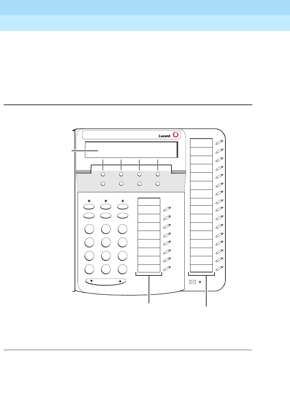
DEFINITYEnterpriseCommunicationsServerandSystem75andSystem85
Terminals and Adjuncts Reference
555-015-201 Issue 11
December 1999
The 6400 Series Telephones
7-49The 6424D+ and 6424D+M Telephone
7
Button Numbering
The following button diagrams of the 6424D+ and 6424D+M telephones will help
you administer the 6424D+ and 6424D+M telephone connected to a DEFINITY
system Release 6.1 or later.
If you need more information, refer to
DEFINITY Communications System
Generic 3 Implementation
, 555-230-653.
Figure 7-10. Button Numbering for Administering the 6424D+ or 6424D+M Telephone
Connected to a DEFINITY System Release 6.1 or Later
7
PQRS
3
DEF
Speaker Mute Hold
Redial Transfer Conf
Test Ring
2
ABC
1
4
GHI
*
56
89
MNOJKL
TUV WXYZ
O#
Volume
Menu Exit Prev Next
Tel #
Administer the first column
of 8 call appearance/
feature buttons as “BUTTON
ASSIGNMENTS” 1 - 8.
Administer the second column
of 16 buttons as “FEATURE
BUTTON ASSIGNMENTS” 9 - 24.
1
2
3
4
5
6
7
8
17
18
19
20
21
22
23
24
9
10
11
12
13
14
15
16
Administer the
1 through 12.
ASSIGNMENTS”
“SOFTKEY BUTTON
features on
12 softkey

DEFINITYEnterpriseCommunicationsServerandSystem75andSystem85
Terminals and Adjuncts Reference
555-015-201 Issue 11
December 1999
The 6400 Series Telephones
7-50The 6424D+ and 6424D+M Telephone
7
Administering the Analog Adjunct on the
Modular 6424D+M Telephone
As noted above, all 6424D+ and 6424D+M telephones can be administered as
themselves ONLY IF they are connected to a DEFINITY ECS Release 6.1 (or
later). In Native Mode the Modular 6424D+M telephone is administered through a
digital line circuit card with a line number (with the usual three call appearances)
assigned to the I-1 Channel. If the Modular 6424D+M is connected to a DEFINITY
ECS Release 8.1 or later, a second line number can be administered through the
same digital line card on the I-2 Channel, but this line number can only be used for
analog adjuncts connected to the Tip/Ring module. This analog adjunct is
assigned a private number, but can be used only for placing or terminating a call.
It cannot be used for any other analog functions such as transferring a call or
setting up a conference call. If a second line on the telephone is administered on
the I-2-Channel (for analog equipment), type “analog” in the Data Option field on
the administration screen.
Power Failure Operation
The 6400 Series telephones cannot be used as an emergency station during
power failure transfer conditions.
FCC Registration
The 6400 Series telephones are FCC-registered along with the switch (as a
system), but do not have a separate FCC registration label.
UL and CSA Approval
The 6400 Series telephones have been tested and have met the Underwriters
Laboratories (UL) Standards UL 1459 and have also met the Canadian Standards
Association (CSA) Standards CSA-C22.2 No.225-M90.
Hearing Aid Compatible
All 6400 Series telephones are compatible with the inductively coupled hearing
aids approved by the FCC.

DEFINITYEnterpriseCommunicationsServerandSystem75andSystem85
Terminals and Adjuncts Reference
555-015-201 Issue 11
December 1999
The 6400 Series Telephones
7-51The 6424D+ and 6424D+M Telephone
7
6424D+ and 6424D+M Equipment PECs and
Comcodes
The 6424D+ and 6424D+M telephones and components can be ordered with
these PECs and Comcodes:
■6424D+ (6424D01A) telephone
Gray 6424D+ Set PEC: 3307-24G
Comcode: 108020553;
White 6424D+ Set PEC: 3307-24W
Comcode: 108020454
■Modular Class B 6424D+M (6424D02A) telephone
Gray 6424D+M Set PEC: 3307-4MG
Comcode: 108331240;
White 6424D+M Set PEC: 3307-4MW
Comcode: 108331257
■AJ2A Handset
Comcode: Gray=220035018; White=220035000
■Handset cord (9 feet)
Comcode: Gray and White cord comcodes not available at this time
■D8W-87 Line cord (7 feet)
PEC: 2725-07G
Comcode: 103786778
■D8W-87 Line cord (14 feet, silver)
PEC: 2725-07N (COL18)
Comcode: 103786828
■D8W-87 Line cord (25 feet, silver)
PEC: 2725-07S (COL18)
Comcode: 103786802
■D2R-87 Line cord (14-feet)
Comcode: 105001861
■Button Designation Card
Laser Sheet For 25 Sets
PEC: 32310A
Comcode: 847770666;
Laser Sheet For 100 Sets
PEC: 32311A
Comcode: 847770674
■100A-266 Tip/Ring Module (White)
PEC: 3305-TR1
Comcode: 108332446
100A-266Tip/Ring Module with 1151A Power Supply
PEC: 3305-TRP

DEFINITYEnterpriseCommunicationsServerandSystem75andSystem85
Terminals and Adjuncts Reference
555-015-201 Issue 11
December 1999
The 6400 Series Telephones
7-52The 6424D+ and 6424D+M Telephone
7
■XM24 Expansion Module (for the non-modular 6416D+ and 6424D+)
Gray XM24 = PEC: 33076/A, Comcode: 108023243
White XM24 = PEC: 33074/A, Comcode: 108023235
■XM24 Expansion Module (with a new base angle for the 6416D+M,
6424D+M, and CALLMASTER V)
Gray XM24 = PEC: 33071/A, Comcode: 108544511
White XM24 = PEC: 33072/A, Comcode: 108554503
Adjuncts
The Modular 6424D+M telephones, with the connected 100A Tip/Ring module in
the desktop stand, allow connection with such analog adjuncts as answering
machines, fax machines, modems, analog speakerphones, and TDD machines
commonly used by the hearing impaired. For more information about these
connections with the 100A Tip/Ring module, see the Adjuncts section later in this
manual.
The non-Modular regular 6424D+ telephones
cannot
accommodate any adjunct
equipment.
NOTE:
The Headsets mentioned below can be plugged into the Handset jack. On
the Modular 6424D+M, there is also a Headset jack to which a headset can
be connected.
Headsets
A list of compatible headsets, consisting of both modular and plug prong base
units and selection of headpieces, appears in “Headset Adapters” in the Adjuncts
section later in this manual.
Additional Documents
The following documents contain additional information relating to the 6424D+
telephone: (Use the 9 digit number listed after each document to order that book
from the BCS Publications Center for Lucent Technologies.)
■
6408+, 6408D+, 6416D+, 6416D+M, 6424D+, and 6424D+M Telephones
User’s Guide
, 555-230-739
■
6400 Series Multi-line Quick Reference Cards
, 555-104-752
■
The Tip/Ring Interface Module Installation and User Instructions,
555-233-707.

The 7100 Series Voice Terminals
8-1
8
DEFINITYEnterpriseCommunicationsServerandSystem75andSystem85
Terminals and Adjuncts Reference
555-015-201 Issue 11
December 1999
8
The 7100 Series Voice Terminals
The following section describes these 7100 Series voice terminals:
■7101A voice terminal
■7102A and 7102 Plus voice terminals
■7103A Fixed Feature voice terminal
■7103A Programmable voice terminal
■7104A voice terminal
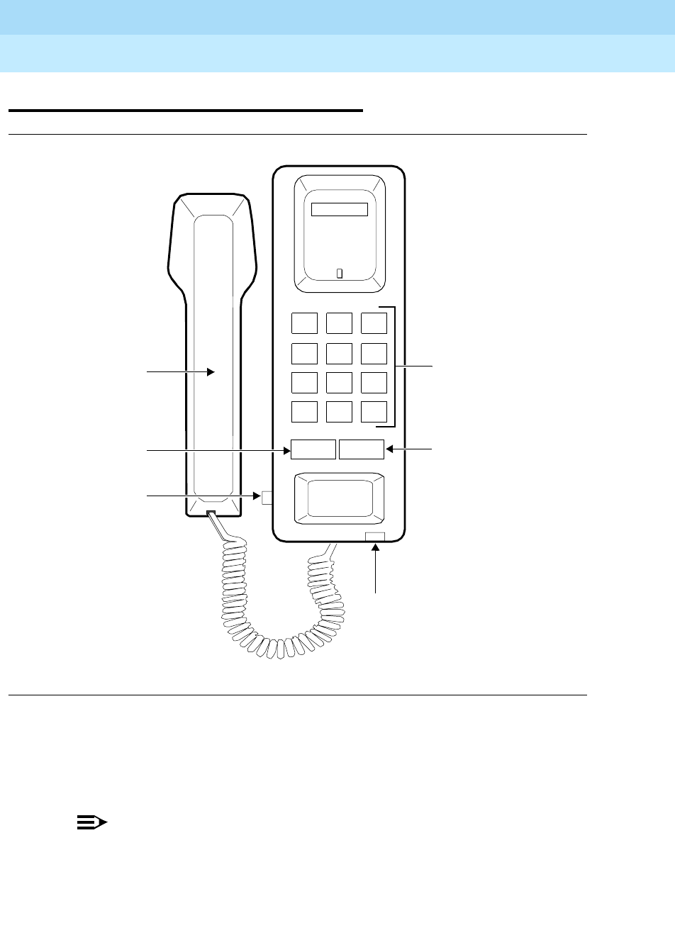
DEFINITYEnterpriseCommunicationsServerandSystem75andSystem85
Terminals and Adjuncts Reference
555-015-201 Issue 11
December 1999
The 7100 Series Voice Terminals
8-2The 7101A Voice Terminal
8
The 7101A Voice Terminal
Figure 8-1. The 7101A Voice Terminal
The 7101A voice terminal is a single-line analog model that requires one tip and
ring pair for operation. It is equipped with a Message Waiting light and a RECALL
button for activating the system’s special features. It cannot be physically bridged
to the same analog line port due to the message waiting and loop current circuitry.
NOTE:
The 7101A has been discontinued.
Dial Pad
Message Light
Msg
123
456
789
ABC DEF
MNOJKLGHI
PRS TUV WXY
*
O#
Oper
Handset
Recall Disconnect
Hi
Lo
Volume
Control
Disconnect
Button
Recall
Button

DEFINITYEnterpriseCommunicationsServerandSystem75andSystem85
Terminals and Adjuncts Reference
555-015-201 Issue 11
December 1999
The 7100 Series Voice Terminals
8-3The 7101A Voice Terminal
8
Applications
The 7101A terminal can be used with the DEFINITY Communications System
Generic 1, Generic 2, and Generic 3, the DEFINITY ECS, System 75, and
System 85. This voice terminal is especially suitable for manufacturing,
warehousing, guard and/or reception areas, or office desks where multiple line
appearances or one touch access to special features is not required.
Physical Description
Dimensions
NOTE:
The following dimensions are approximate.
Width = 3-3/4 inches
Depth (front to back) = 8-3/4 inches
Height (maximum with handset in place) = 5-1/2 inches
Thickness of housing = 1-1/2 inches
Features
Two Fixed Feature Buttons
■RECALL button
■DISCONNECT button
Message Light
The green Message light goes on when a message is left for the user.
It goes off when the user retrieves the message.
Other Physical Features
Handset
The 7101A is equipped with an R-type handset.
Dial pad
The 7101A has a 12-button touch-tone dial pad.

DEFINITYEnterpriseCommunicationsServerandSystem75andSystem85
Terminals and Adjuncts Reference
555-015-201 Issue 11
December 1999
The 7100 Series Voice Terminals
8-4The 7101A Voice Terminal
8
Jacks
The 7101A housing contains two jacks. The handset cord jack is just under the left
front edge of the housing. (The handset contains a jack for the other end of the
handset cord.) The line jack is on the bottom center of the housing.
Cords
Two cords are supplied with the 7101A terminal: a coiled 7-foot modular handset
cord and a 7-foot modular line cord. Optional longer cords are available: a
12-foot handset cord, and 14-foot and 25-foot line cords.
Ringing
The 7101A has electronic tone ringing. The volume control is on the left side of
the housing.
Mounting Options
The 7101A comes equipped with a non-adjustable desk stand. An optional wall
mounting kit may be ordered.
Color Options
The 7101A is available in black only.

DEFINITYEnterpriseCommunicationsServerandSystem75andSystem85
Terminals and Adjuncts Reference
555-015-201 Issue 11
December 1999
The 7100 Series Voice Terminals
8-5The 7101A Voice Terminal
8
Distance Limitations
The maximum allowable distances of a 7101A from the DEFINITY G1, G2, and
G3, DEFINITY ECS, System 75, or System 85 cabinet are shown in the table
below.
Power Requirements
The 7101A is powered by the tip and ring leads. It does not require any external
power supply.
Power Failure Operation
The 7101A cannot be used as an emergency station during power failure transfer
conditions.
FCC Registration
The 7101A is not FCC registered.
Table 8-1. Distance Limitations for the 7101A Voice Terminal
System Port Board
Nominal Maximum Range in Feet
(Meters)
24 AWG 26 AWG
System 85 SN229
SN228B
3,500 (1,067)
15,000 (4,572)
3,500 (1,067)
9,000 (2,743)
DEFINITY G2 SN229
SN228B
TN742
TN746*
* The 7101A cannot be used with the TN746 Port Circuit Pack.
3,500 (1,067)
15,000 (4,572)
15,200 (4,633)
—
3,500 (1,067)
9,000 (2,743)
10,000 (3,050)
—
DEFINITY G1 and
G3, DEFINITY
ECS, and System
75
TN742
TN769
TN746*
15,200 (4,633)
15,200 (4,633)
—
10,000 (3,050)
10,000 (3,050)
—

DEFINITYEnterpriseCommunicationsServerandSystem75andSystem85
Terminals and Adjuncts Reference
555-015-201 Issue 11
December 1999
The 7100 Series Voice Terminals
8-6The 7101A Voice Terminal
8
Hearing Aid Compatible
The 7101A voice terminal is compatible with the inductively coupled hearing aids
prescribed by the FCC.
7101A Equipment PECs
The 7101A Voice Terminal and optional components were ordered with the
following PECs:
■Basic 7101A Voice Terminal (black) — 3170-00M
■Handset cord (12 feet, black) — 2725-01L COL09
■Line cord (14 feet, silver) — 2725-07N COL18
■Line cord (25 feet, silver) — 2725-07S COL18
Adjuncts
The 7101A does not have an adjunct jack.
Additional Documents
The following documents contain additional information relating to the 7101A
Voice Terminal:
■
DEFINITY Generic 1 and System 75 7101A Voice Terminal User’s Guide
,
555-200-709
■
DEFINITY Generic 2 and System 85 7101A Voice Terminal User
’
sGuide
,
999-700-047
■
DEFINITY Generic 1 and Generic 2, System 75, and System 85 Terminals
and Adjuncts Installation and Test
, 555-015-104
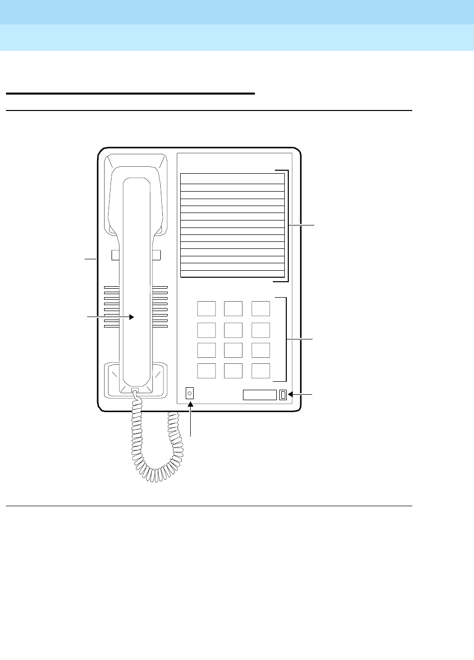
DEFINITYEnterpriseCommunicationsServerandSystem75andSystem85
Terminals and Adjuncts Reference
555-015-201 Issue 11
December 1999
The 7100 Series Voice Terminals
8-7The 7102A and 7102 Plus Voice Terminals
8
The 7102A and 7102 Plus Voice
Terminals
Figure 8-2. The 7102A and 7102 Plus Voice Terminals
The 7102A voice terminal is available in two versions, the 7102A01A and the
710201B, called the 7102 Plus. The front of the two sets is exactly the same in
appearance. The only difference is that the 7102A01B is equipped with an adjunct
jack. This jack allows speakerphone/headset capability.
Dial Pad
Message Light
Recall Button
Message
123
456
789
ABC DEF
MNOJKLGHI
PRS TUV WXY
*
O#
Oper
Access Codes Card
Ringer
Volume Control
(on left side)
Handset
Recall
DEFINITYEnterpriseCommunicationsServerandSystem75andSystem85
Terminals and Adjuncts Reference
555-015-201 Issue 11
December 1999
The 7100 Series Voice Terminals
8-8The 7102A and 7102 Plus Voice Terminals
8
The 7102A and the 7102 Plus voice terminals are single-line analog models that
require one tip and ring pair for operation. It allows access to system features via
the RECALL Button and dial codes. The 7102A and 7102 Plus voice terminal
faceplate contains a Feature Access Code Card that can be customized to reflect
the most frequently accessed features.
NOTE:
Both of the 7102 voice terminals have been discontinued.
Applications
The 7102A and 7102 Plus voice terminals can be used with the DEFINITY
Communications System Generic 1, Generic 2, and Generic 3, the DEFINITY
ECS, System 75, and System 85. The 7102 voice terminals are especially
suitable for manufacturing, warehousing, guard and/or reception areas, or office
desks where multiple line appearances or one-touch access to special features is
not required.
Physical Description
Dimensions
NOTE:
The following dimensions for the 7102A and the 7102 Plus are approximate.
Width = 7 inches
Depth (front to back) = 8-3/4 inches
Height (maximum with handset in place) = 5-1/2 inches
Thickness of housing = 1-1/2 inches
Features
One Fixed Feature Button
■The RECALL Button
Message Light
The red Message light flashes when a message is left for the user. It goes off
when the user retrieves the message.

DEFINITYEnterpriseCommunicationsServerandSystem75andSystem85
Terminals and Adjuncts Reference
555-015-201 Issue 11
December 1999
The 7100 Series Voice Terminals
8-9The 7102A and 7102 Plus Voice Terminals
8
Other Physical Features
Handset
The 7102 voice terminals are equipped with an R-type handset.
Dial Pad
The 7102 voice terminals have a 12-button touch-tone dial pad.
Jacks
The 7102A01A housing contains two jacks. The handset cord jack is just under
the center front edge of the housing. (The handset contains a jack for the other
end of the handset cord.) The line jack is on the bottom center of the housing.
The 7102 Plus housing contains three jacks. The handset cord jack is just under
the center front edge of the housing. (The handset contains a jack for the other
end of the handset cord.) The line jack is on the bottom center of the housing. The
modular speakerphone/headset jack is located on bottom of the set.
Cords
Two cords are supplied with the 7102 voice terminals: a coiled 7-foot modular
handset cord and a 7-foot modular line cord. Optional longer cords are available:
a 12-foot handset cord, and 14-foot and 25-foot line cords.
Ringing
The 7102 voice terminals have electronic tone ringing. The volume control is on
the left side of the housing.
Mounting Options
The 7102 voice terminals come equipped with both a non-adjustable desk stand
and a wall mounting bracket.
Color Options
The 7102 voice terminals are available in two colors: black and misty cream.
DEFINITYEnterpriseCommunicationsServerandSystem75andSystem85
Terminals and Adjuncts Reference
555-015-201 Issue 11
December 1999
The 7100 Series Voice Terminals
8-10The 7102A and 7102 Plus Voice Terminals
8
Distance Limitations
The maximum allowable distances of a 7102A or 7102 Plus voice terminal from
the DEFINITY G1, G2, and G3, DEFINITY ECS, System 75, or System 85 cabinet
are shown in the table below.
Power Requirements
The 7102 voice terminals are powered by the tip and ring leads. These voice
terminals do not require any external power supply.
Power Failure Operation
The 7102A and the 7102 Plus voice terminals can be used as an emergency
station during power failure transfer conditions but will not support any adjuncts.
If the 7102A or 7102 Plus voice terminal is being used as an emergency station
for a DEFINITY G1 or G3, DEFINITY ECS, or System 75 that is equipped with a
Z1A Emergency Transfer Unit, a ground start switch (551A and 77A bracket) is
required. Installation instructions can be found in the
DEFINITY Communications
System Generic 1 and Generic 3 Wiring Guide
, 555-204-111.
FCC Registration
The 7102 voice terminals are FCC registered (AS-593M-17706-TE-T).
Table 8-2. Distance Limitations for the 7102A and 7102 Plus Voice Terminals
System Port Board
Nominal Maximum Range in Feet
(Meters)
24 AWG 26 AWG
System 85 SN229
SN228B
3,500 (1,067)
28,400 (8,662)
3,500 (1,067)
17,900 (5,460)
DEFINITY G2 SN229
SN228B
TN742
TN746
3,500 (1,067)
28,400 (8,662)
15,200 (4,633)
3,000 (915)
3,500 (1,067)
17,900 (5,460)
10,000 (3,050)
2,000 (610)
DEFINITY G1 and
G3, DEFINITY
ECS, and System
75
TN742
TN769
TN746
15,200 (4,633)
15,200 (4,633)
3,000 (915)
10,000 (3,050)
10,000 (3,050)
2,000 (610)

DEFINITYEnterpriseCommunicationsServerandSystem75andSystem85
Terminals and Adjuncts Reference
555-015-201 Issue 11
December 1999
The 7100 Series Voice Terminals
8-11The 7102A and 7102 Plus Voice Terminals
8
Hearing Aid Compatible
This voice terminal is compatible with the inductively coupled hearing aids
prescribed by the FCC.
7102 Equipment PECs
The 7102A and the 7102 Plus voice terminals and optional components were
ordered with the following PECs:
■7102A voice terminal (black and misty cream) — 3185-MWR
(not orderable)
■7102 Plus Voice Terminal (black and misty cream) — 3188-MWS
(not orderable)
■Handset cord (12 feet, black) — 2725-01L COL09
■Line cord (14 feet, silver) — 2725-07N COL18
■Line cord (25 feet, silver) — 2725-07S COL18
Adjuncts
The 7102A01A cannot be equipped with any adjuncts. The 7102A01B can be
equipped with one of the following adjuncts:
■S101A Speakerphone
■S201A Speakerphone
■500A Headset Adapter with a standard headset
Additional Documents
The following documents contain additional information relating to the 7102A
voice terminal:
■
DEFINITY Generic 1 7102 Voice Terminal User’s Guide
, 555-204-728
■
System 75 7102 Voice Terminal User’s Guide
, 555-200-728
■
DEFINITY Generic 2 and System 85 7102 Voice Terminal User’s Guide
,
555-104-715
■
DEFINITY Generic 1 and Generic 2, System 75, and System 85 Terminals
and Adjuncts Installation and Test
, 555-015-104
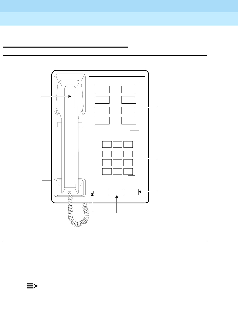
DEFINITYEnterpriseCommunicationsServerandSystem75andSystem85
Terminals and Adjuncts Reference
555-015-201 Issue 11
December 1999
The 7100 Series Voice Terminals
8-12The 7103A Fixed Feature Voice Terminal
8
The 7103A Fixed Feature Voice
Terminal
Figure 8-3. The 7103A Fixed Feature Voice Terminal
The 7103A Fixed Feature voice terminal is a single-line analog model The feature
buttons on this terminal must be programmed by the system manager. It requires
one tip and ring pair for operation. It cannot be physically bridged to the same
analog line port due to the message waiting and loop current circuitry.
NOTE:
The 7103AFixed Feature voice terminal has been discontinued.
Message
123
456
789
ABC DEF
MNOJKLGHI
PRS TUV WXY
*
O#
OPER
Dial Pad
Message
Recall Disconnect
8 Feature Buttons
Light Recall
Button
Disconnect
Button
Volume
Control
(on left side)
Handset

DEFINITYEnterpriseCommunicationsServerandSystem75andSystem85
Terminals and Adjuncts Reference
555-015-201 Issue 11
December 1999
The 7100 Series Voice Terminals
8-13The 7103A Fixed Feature Voice Terminal
8
Applications
The 7103A Fixed Feature voice terminal can be used with the DEFINITY
Communications System Generic 1, Generic 2, and Generic 3, the DEFINITY
ECS, System 75, and System 85. This voice terminal is especially suitable for
groups of office workers who make frequent calls to the same destinations or use
thesamefeatures.
Physical Description
Dimensions
NOTE:
The following dimensions are approximate.
Width = 7 inches
Depth (front to back) = 8-3/4 inches
Height (maximum with handset in place) = 5-1/2 inches
Thickness of housing = 1-1/2 inches
Features
Two Fixed Feature Buttons
■RECALL button
■DISCONNECT button
Eight Feature Buttons
The system manager designates and programs all buttons, except fixed feature
buttons, for the common needs of all voice terminal users. Within any one system,
all 7103A Fixed Feature voice terminals have identical features at the same button
positions.
Message Light
The green Message light goes on when a message is left for the user. It goes off
when the user retrieves the message.
Other Physical Features
Handset
The 7103A Fixed Feature voice terminal is equipped with an R-type handset.

DEFINITYEnterpriseCommunicationsServerandSystem75andSystem85
Terminals and Adjuncts Reference
555-015-201 Issue 11
December 1999
The 7100 Series Voice Terminals
8-14The 7103A Fixed Feature Voice Terminal
8
Dial pad
The 7103A Fixed Feature voice terminal has a 12-button touch-tone dial pad.
Jacks
The 7103A Fixed Feature voice terminal housing contains three jacks. The
handset cord jack is just under the left side of the housing. (The handset contains
a jack for the other side of the handset cord.) The LINE and OTHER jacks are on
the bottom center of the housing.
Cords
Two cords are supplied with the 7103A Fixed Feature voice terminal: a coiled 7-
foot modular handset cord and a 7-foot modular line cord. Optional longer cords
are available: a 12-foot handset cord, and 14-foot and 25-foot line cords.
Ringing
The 7103A Fixed Feature voice terminal has electronic tone ringing. The volume
control is on the left side of the housing.
Mounting Options
The 7103A Fixed Feature voice terminal comes equipped with a nonadjustable
desk stand. An adjustable desk stand or a wall mounting bracket can be optionally
ordered.
Color Options
The 7103A Fixed Feature voice terminal is available in black only.
DEFINITYEnterpriseCommunicationsServerandSystem75andSystem85
Terminals and Adjuncts Reference
555-015-201 Issue 11
December 1999
The 7100 Series Voice Terminals
8-15The 7103A Fixed Feature Voice Terminal
8
Distance Limitations
The maximum allowable distances of a 7103A Fixed Feature voice terminal from
the DEFINITY G1, G2, and G3, DEFINITY ECS, System 75, or System 85 cabinet
are shown in the table below.
Power Requirements
The 7103A Fixed Feature voice terminal is powered by the tip and ring leads. If
the 7103A Fixed Feature voice terminal is equipped with any adjunct, auxiliary
power will be required for the adjunct. Refer to the Adjunct Power section earlier
in this manual.
Power Failure Operation
The 7103A Fixed Feature voice terminal cannot be used as an emergency station
during power failure transfer conditions.
FCC Registration
The 7103A Fixed Feature voice terminal is not FCC registered.
Table 8-3. Distance Limitations for the 7103A Fixed Feature Voice Terminal
System Port Board
Nominal Maximum Range in Feet
(Meters)
24 AWG 26 AWG
System 85 SN229
SN228B
3,500 (1,067)
15,000 (4,572)
3,500 (1,067)
9,000 (2,743)
DEFINITY G2 SN229
SN228B
TN742
TN746*
* The 7103A cannot be used with the TN746 Port Circuit Pack.
3,500 (1,067)
15,000 (4,572)
15,200 (4,633)
—
3,500 (1,067)
9,000 (2,743)
10,000 (3,050)
—
DEFINITY G1 and
G3, DEFINITY
ECS, and System
75
TN742
TN769
TN746*
15,200 (4,633)
15,200 (4,633)
—
10,000 (3,050)
10,000 (3,050)
—

DEFINITYEnterpriseCommunicationsServerandSystem75andSystem85
Terminals and Adjuncts Reference
555-015-201 Issue 11
December 1999
The 7100 Series Voice Terminals
8-16The 7103A Fixed Feature Voice Terminal
8
Hearing Aid Compatible
The 7103 Fixed Feature voice terminal is compatible with the inductively coupled
hearing aids prescribed by the FCC.
7103A (Fixed Feature) Equipment PECs
The 7103A Fixed Feature voice terminal and optional components were ordered
with the following PECs:
■Basic 7103A Fixed Feature Voice Terminal — (not orderable)
■Handset cord (12 feet, black) — 2725-01L COL09
■Line cord (14 feet, silver) — 2725-07N COL18
■Line cord (25 feet, silver) — 2725-07S COL18
Adjuncts
One of the following adjuncts can be used with this voice terminal:
■S101A Speakerphone
■S201A Speakerphone
■500A Headset Adapter with a standard headset
Additional Documents
The following documents contain additional information relating to the 7103A
Fixed Feature voice terminal:
■
DEFINITY Generic 1 and System 75 7103A Voice Terminal User’s Guide
,
555-200-710
■
DEFINITY Generic 2 and System 85 7103A Voice Terminal User’s Guide
,
999-700-048
■
DEFINITY Generic 1 and Generic 2, System 75, and System 85 Terminals
and Adjuncts Installation and Test
, 555-015-104
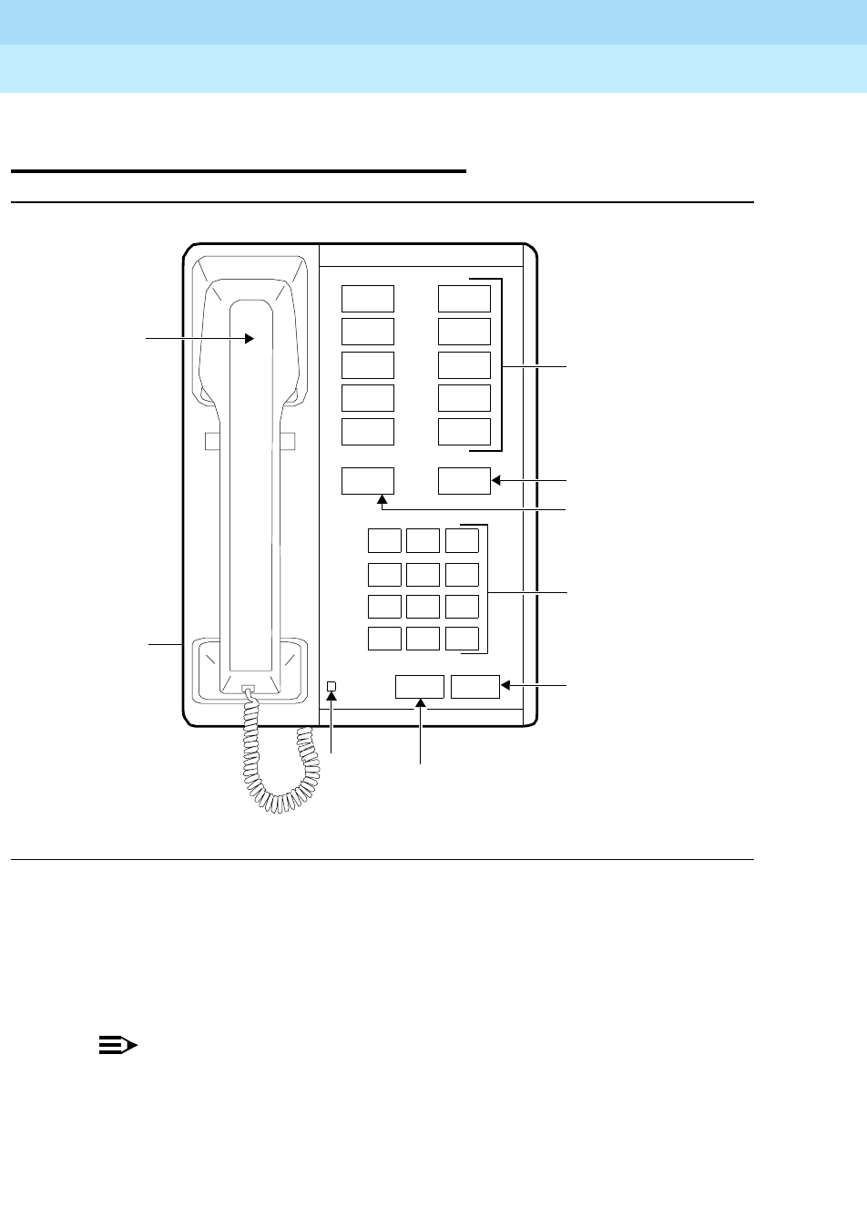
DEFINITYEnterpriseCommunicationsServerandSystem75andSystem85
Terminals and Adjuncts Reference
555-015-201 Issue 11
December 1999
The 7100 Series Voice Terminals
8-17The 7103A Programmable Voice Terminal
8
The 7103A Programmable Voice
Terminal
Figure 8-4. The 7103A Programmable Voice Terminal
The 7103 Programmable voice terminal is a single-line analog model. The 10
feature buttons can be programmed by the user for one-touch feature access or
for one-touch Speed Dialing. It requires one tip and ring pair for operation. It
cannot be physically bridged to the same analog line port due to the message
waiting and loop current circuitry.
NOTE:
The 7103 Programmable voice terminal is no longer manufactured.
However, some remanufactured terminals may still be ordered.
Message
123
456
789
ABC DEF
MNOJKLGHI
PRS TUV WXY
*
O#
OPER
Dial Pad
Message
Recall Disconnect
10 Feature Buttons
Light Recall
Button
Disconnect
Button
Volume
Control
(on left side)
Handset
Program Last
Number/Wait
Last Number/
Wait Button
Program Button

DEFINITYEnterpriseCommunicationsServerandSystem75andSystem85
Terminals and Adjuncts Reference
555-015-201 Issue 11
December 1999
The 7100 Series Voice Terminals
8-18The 7103A Programmable Voice Terminal
8
Applications
The 7103A Programmable voice terminal can be used with the DEFINITY
Communications System Generic 1, Generic 2, and Generic 3, the DEFINITY
ECS, System 75, and System 85. This voice terminal is especially suitable for
groups of office workers who make frequent calls to the same destinations or use
thesamefeatures.
Physical Description
Dimensions
NOTE:
The following dimensions are approximate.
Width = 7 inches
Depth (front to back) = 8-3/4 inches
Height (maximum with handset in place) = 5-1/2 inches
Thickness of housing = 1-1/2 inches
Features
Four Fixed Feature Buttons
■RECALL button
■DISCONNECT button
■LAST NUMBER/WAIT button — This is a dual function button. In its normal
(Last Number) mode, this button is used to automatically redial the last
number dialed; in the Wait mode, it is used to enter a delay in a number
being stored on a feature button.
■PROGRAM button — This button is used to enter mode for programming
feature buttons for feature access or for Repertory Dialing. With the
Repertory Dialing feature, the terminal user can store in-house or external
numbers. Operation of this button also puts the Last Number/Wait button
into the Wait mode.
Ten User-Programmable Feature Buttons
The 10 programmable buttons allow each user to enter often-used telephone
numbers or choose the most desirable features provided by the system.

DEFINITYEnterpriseCommunicationsServerandSystem75andSystem85
Terminals and Adjuncts Reference
555-015-201 Issue 11
December 1999
The 7100 Series Voice Terminals
8-19The 7103A Programmable Voice Terminal
8
Message Light
The green Message light goes on when a message is left for the user. It goes off
when the user retrieves the message.
Other Physical Features
Handset
The 7103A Programmable voice terminal is equipped with an R-type handset.
Dial pad
The 7103A Programmable voice terminal has a 12-button touch-tone dial pad.
Jacks
The 7103A Programmable voice terminal housing contains three jacks. The
handset cord jack is just under the left side of the housing. (The handset contains
a jack for the other end of the handset cord.) The LINE and OTHER jacks are on
the bottom center of the housing.
Cords
Two cords are supplied with the 7103A Programmable voice terminal: a coiled
7-foot modular handset cord and a 7-foot modular line cord. Optional longer cords
are available: a 12-foot handset cord, and14-foot and 25-foot line cords.
Ringing
The 7103A Programmable voice terminal has electronic tone personalized
ringing. The personalized ringing is controlled by two ring switches on the bottom
of the voice terminal. The volume control is on the left side of the housing.
Mounting Options
The 7103A Programmable voice terminal comes equipped with a nonadjustable
desk stand. An adjustable desk stand or a wall mounting bracket can be optionally
ordered.
Color Options
The 7103A Programmable voice terminal is available in black only.
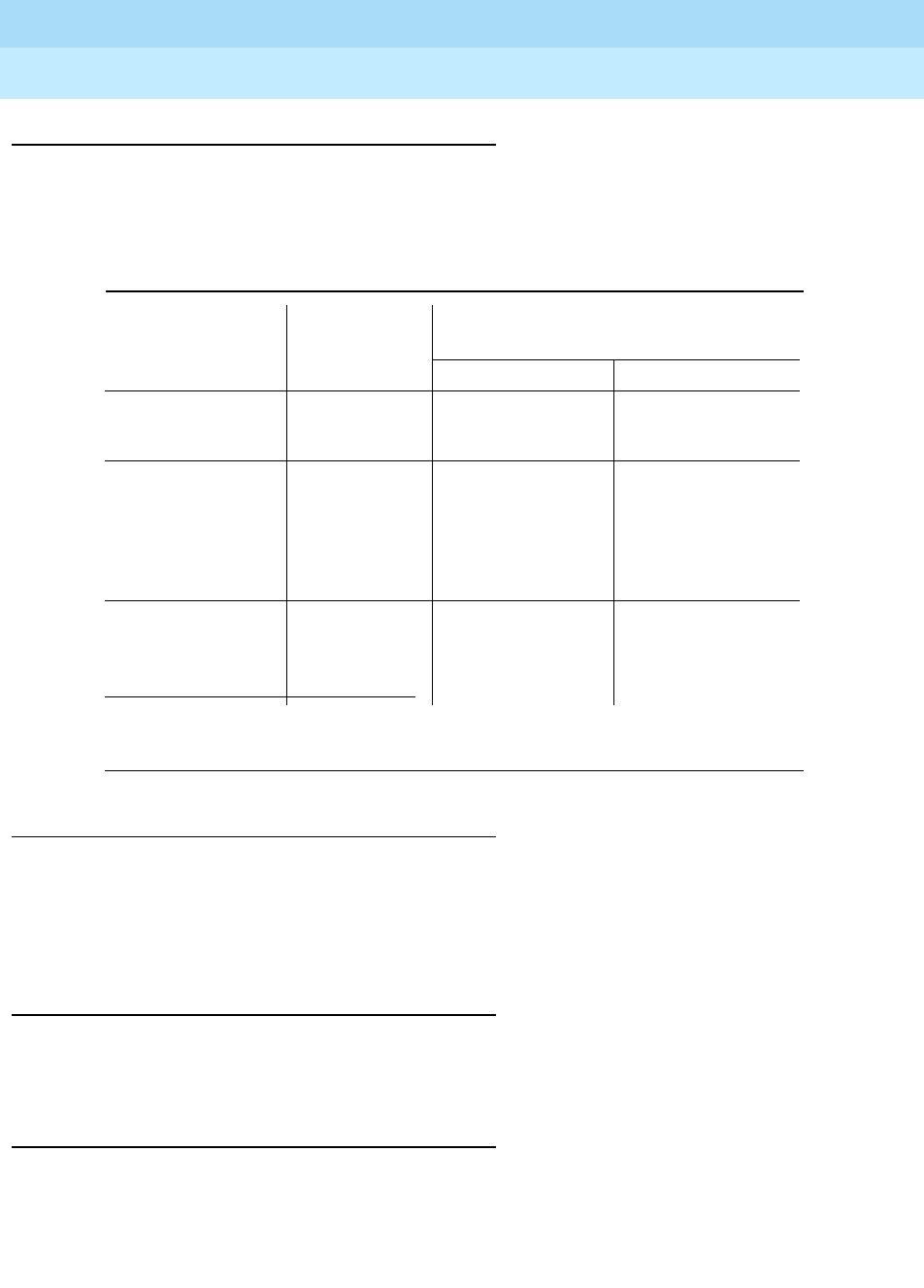
DEFINITYEnterpriseCommunicationsServerandSystem75andSystem85
Terminals and Adjuncts Reference
555-015-201 Issue 11
December 1999
The 7100 Series Voice Terminals
8-20The 7103A Programmable Voice Terminal
8
Distance Limitations
The maximum allowable distances of a 7103A Programmable voice terminal from
the DEFINITY G1, G2, and G3, DEFINITY ECS, System 75, or System 85 cabinet
are shown in the table below.
Power Requirements
The 7103A Programmable voice terminal is powered by the tip and ring leads. If
the 7103A voice terminal is equipped with any adjunct, auxiliary power will be
required for the adjunct. Refer to the Adjunct Power section earlier in this
manual.
Power Failure Operation
The 7103A Programmable voice terminal cannot be used as an emergency
station during power failure transfer conditions.
FCC Registration
The 7103A Programmable voice terminal is not FCC registered.
Table 8-4. Distance Limitations for the 7103A Programmable Voice Terminal
System Port Board
Nominal Maximum Range in Feet
(Meters)
24 AWG 26 AWG
System 85 SN229
SN228B
3,500 (1,067)
15,000 (4,572)
3,500 (1,067)
9,000 (2,743)
DEFINITY G2 SN229
SN228B
TN742
TN746*
* The 7103A cannot be used with the TN746 Port Circuit Pack.
3,500 (1,067)
15,000 (4,572)
15,200 (4,633)
—
3,500 (1,067)
9,000 (2,743)
10,000 (3,050)
—
DEFINITY G1 and
G3, DEFINITY
ECS, and System
75
TN742
TN769
TN746*
15,200 (4,633)
15,200 (4,633)
—
10,000 (3,050)
10,000 (3,050)
—

DEFINITYEnterpriseCommunicationsServerandSystem75andSystem85
Terminals and Adjuncts Reference
555-015-201 Issue 11
December 1999
The 7100 Series Voice Terminals
8-21The 7103A Programmable Voice Terminal
8
Hearing Aid Compatible
The 7103A Programmable voice terminal is compatible with the inductively
coupled hearing aids prescribed by the FCC.
7103A (Programmable) Equipment PECs
The 7103A Programmable voice terminal and optional components were ordered
with the following PECs:
■Basic 7103A Programmable Voice Terminal — 3171-14F
■Handset cord (12 feet, black) — 2725-01L COL09
■Line cord (14 feet, silver) — 2725-07N COL18
■Line cord (25 feet, silver) — 2725-07S COL18
Adjuncts
One of the following adjuncts can be used with this voice terminal:
■S101A Speakerphone
■S102A Speakerphone
■500A Headset Adapter with a standard headset
Additional Documents
The following documents contain additional information relating to the 7103A
Programmable voice terminal:
■
DEFINITY Generic 1 and System 75 7103A Voice Terminal User’s Guide
,
555-200-717
■
DEFINITY Generic 2 and System 85 7103A Voice Terminal User’s Guide
,
999-700-464
■
DEFINITY Generic 1 and Generic 2, System 75, and System 85 Terminals
and Adjuncts Installation and Test
, 555-015-104
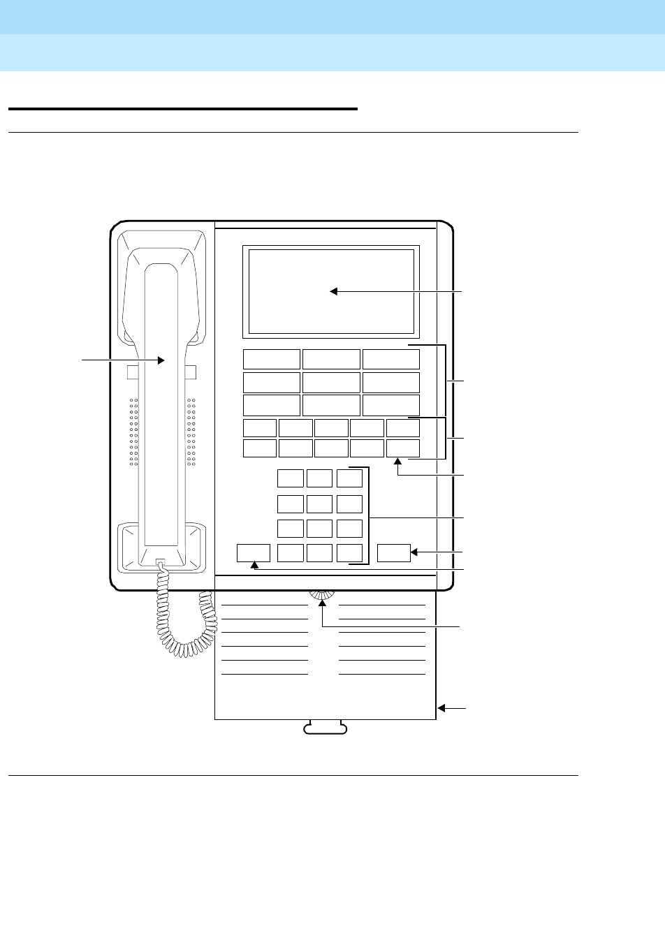
DEFINITYEnterpriseCommunicationsServerandSystem75andSystem85
Terminals and Adjuncts Reference
555-015-201 Issue 11
December 1999
The 7100 Series Voice Terminals
8-22The 7104A Voice Terminal
8
The 7104A Voice Terminal
Figure 8-5. The 7104A Voice Terminal
123
456
789
ABC DEF
MNOJKLGHI
PRS TUV WXY
*
O#
OPER
Dial Pad
9 One-Touch
Dial Buttons
Handset
SpeakerDisconnect
Speaker
Volume
Control
Instruction
Card
Display
Feature Control
Buttons
Recall
Recall Button
Speaker Button
Disconnect
Button
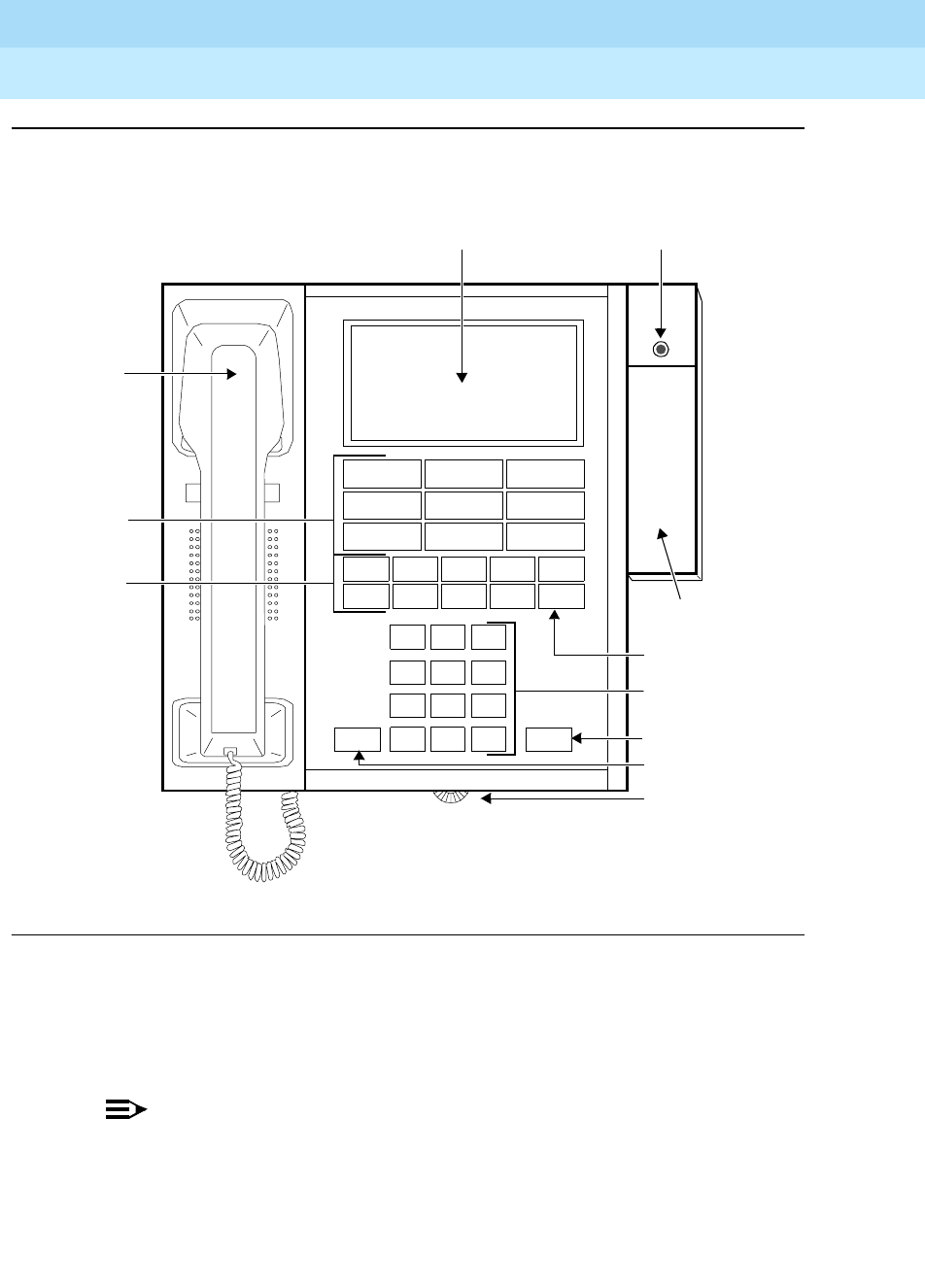
DEFINITYEnterpriseCommunicationsServerandSystem75andSystem85
Terminals and Adjuncts Reference
555-015-201 Issue 11
December 1999
The 7100 Series Voice Terminals
8-23The 7104A Voice Terminal
8
Figure 8-6. The 7104A Voice Terminal with Attached Message Waiting Adjunct
The 7104A voice terminal is a single-line analog model. This voice terminal is
equipped with a display that is used to display stored numbers. It requires one tip
and ring pair for operation. It cannot be physically bridged to the same analog line
port due to the message waiting and loop current circuitry.
NOTE:
The 7104A voice terminal is no longer manufactured. However, some
remanufactured terminals may still be ordered.
123
456
789
ABC DEF
MNOJKLGHI
PRS TUV WXY
*
O#
OPER
Dial Pad
9 One-Touch
Dial Buttons
Handset
SpeakerDisconnect
Speaker Volume
Control
Display
Feature
Recall
Recall Button
Speaker Button
Disconnect Button
Message
Message
Waiting Light
Waiting Adjunct
Buttons
Control

DEFINITYEnterpriseCommunicationsServerandSystem75andSystem85
Terminals and Adjuncts Reference
555-015-201 Issue 11
December 1999
The 7100 Series Voice Terminals
8-24The 7104A Voice Terminal
8
Applications
The 7104A voice terminal can be used with the DEFINITY Communications
System Generic 1 and Generic 3, the DEFINITY ECS, and System 75. This voice
terminal is especially suitable for managers, office support personnel, and others.
Physical Description
Dimensions
NOTE:
The following dimensions are approximate.
Width = 8 inches
Depth (front to back) = 8-3/4 inches
Height (maximum with handset in place) = 5-1/2 inches
Thickness of housing = 1-1/2 inches
Features
Two Fixed Feature Buttons
■RECALL button
■DISCONNECT button
Eight Special Fixed Feature Buttons
■SHIFT button — used for toggling between the two modes of the following
four dual function feature buttons and the eight dual function one-touch
dialing buttons
■SET CLOCK/TIMER button — used for setting time and for timing a call
■AM/DLYD RING button — used in time-setting procedure and to delay
ringing on incoming calls
■PM/ABRV RING button — used in time-setting procedure and to provide
abbreviated ringing on incoming calls

DEFINITYEnterpriseCommunicationsServerandSystem75andSystem85
Terminals and Adjuncts Reference
555-015-201 Issue 11
December 1999
The 7100 Series Voice Terminals
8-25The 7104A Voice Terminal
8
■SAVE/SEND button — used to save a dialed number, then call it again
■PROGRAM button — used in recording numbers for one-touch dialing
■DISPLAY button — used to display stored numbers
■SPACE, PAUSE, and STOP buttons — used in recording numbers for
one-touch dialing
Eight dual function buttons
These buttons are divided into gray and blue halves and can be programmed for
one-touch dialing of sixteen frequently called numbers and/or system features.
Loudspeaker
The 7104A voice terminal has a built in loudspeaker for group listening and
on-hook dialing. The loudspeaker can be turned on and off with the SPEAKER
button.
Display
A 14-Character Liquid Crystal Display (LCD) provides the following displays. Each
display is local to the individual terminal.
Abbreviated Ring mode in effect Number programmed
Date Program mode in effect
Delayed Ring mode in effect Shift mode in effect
Display mode in effect Speaker on
Low Battery Time
Number called
Pull out tray
The 7104A voice terminal is equipped with a pull out tray with an instruction card
for voice terminal operation.
Other Physical Features
Handset
The 7104A voice terminal is equipped with an R-type handset.
Dial pad
The 7104A voice terminal has a 12-button touch-tone dial pad.
Jacks
The 7104A voice terminal housing contains two jacks. The handset cord jack is
just under the left side of the housing. (The handset contains a jack for the other
end of the handset cord.) The line jack is on the bottom center of the housing.

DEFINITYEnterpriseCommunicationsServerandSystem75andSystem85
Terminals and Adjuncts Reference
555-015-201 Issue 11
December 1999
The 7100 Series Voice Terminals
8-26The 7104A Voice Terminal
8
Cords
Two cords are supplied with the 7104A voice terminal: a coiled 7-foot modular
handset cord and a 7-foot modular line cord. Optional longer cords are available:
a 12-foot handset cord, and14-foot and 25-foot line cords.
Ringing
The 7104A voice terminal has electronic tone personalized ringing. The
personalized ringing is controlled by a ring switch under the rear end cap of the
voice terminal. The volume control is on the left side of the housing.
Mounting Options
The 7104A voice terminal comes equipped with a nonadjustable desk stand.
Color Options
The 7104A voice terminal is available in three colors: black, misty cream, and
chocolate brown.
Distance Limitations
The maximum allowable distances of a 7104A voice terminal from the DEFINITY
G1 and G3, DEFINITY ECS, and System 75 cabinet are shown in the table below.
Power Requirements
The 7104A voice terminal is powered by the tip and ring leads. Battery power is
used for some circuits during the on-hook state when loop current is not available.
The battery power is provided by four 1.5 volt AA batteries. The batteries are
contained in a battery pack that is accessed through the rear end cap.
Power Failure Operation
The 7104A voice terminal cannot be used as an emergency station during power
failure transfer conditions.
Table 8-5. Distance Limitations for the 7104A Voice Terminal
System Port Board
Nominal Maximum Range in Feet
(Meters)
24 AWG 26 AWG
DEFINITY G1 and
G3, DEFINITY
ECS, and
SYSTEM 75
TN742
TN769
TN746
15,200 (4,633)
15,200 (4,633)
3,000 (915)
10,000 (3,050)
10,000 (3,050)
2,000 (610)

DEFINITYEnterpriseCommunicationsServerandSystem75andSystem85
Terminals and Adjuncts Reference
555-015-201 Issue 11
December 1999
The 7100 Series Voice Terminals
8-27The 7104A Voice Terminal
8
FCC Registration
The 7104A voice terminal is not FCC registered.
Hearing Aid Compatible
The 7104A voice terminal is compatible with the inductively coupled hearing aids
prescribed by the FCC.
7104A Equipment PECs
The 7104A voice terminal and optional components were ordered with the
following PECs:
■Basic 7104A Voice Terminal (black, misty cream, and chocolate brown) —
3150-010
■Handset cord (12 feet, black) — 2725-01L COL09
■Line cord (14 feet, silver) — 2725-07N COL18
■Line cord (25 feet, silver) — 2725-07S COL18
Adjuncts
The optional Z34A Message waiting Adjunct can be used with the 7104A voice
terminal to provide a visual message waiting indication.
Additional Documents
The following documents contain additional information relating to the 7104A
voice terminal:
■
DEFINITY Generic 1 and System 75 7104A Voice Terminal User’s Guide
,
555-015-720
■
DEFINITY Generic 1 and Generic 2, System 75, and System 85 Terminals
and Adjuncts Installation and Test
, 555-015-104

DEFINITYEnterpriseCommunicationsServerandSystem75andSystem85
Terminals and Adjuncts Reference
555-015-201 Issue 11
December 1999
The 7100 Series Voice Terminals
8-28The 7104A Voice Terminal
8

The 7200 Series Voice Terminals
9-1
9
DEFINITYEnterpriseCommunicationsServerandSystem75andSystem85
Terminals and Adjuncts Reference
555-015-201 Issue 11
December 1999
9
The 7200 Series Voice Terminals
This section describes the following 7200 Series voice terminals:
■7203H voice terminal
■7205H voice terminal
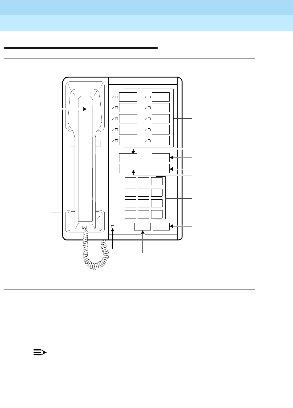
DEFINITYEnterpriseCommunicationsServerandSystem75andSystem85
Terminals and Adjuncts Reference
555-015-201 Issue 11
December 1999
The 7200 Series Voice Terminals
9-2The 7203H Voice Terminal
9
The 7203H Voice Terminal
Figure 9-1. The 7203H Voice Terminal
The 7203H voice terminal is a multi-appearance hybrid voice terminal which
provides up to 10 incoming lines. Buttons not used for line appearances may be
used for one-touch feature access or for Speed Dialing. It requires three pair
wiring for operation. One wire pair is used for analog voice, while the other two
pairs are used for digital control and signaling.
NOTE:
The 7203H voice terminal was discontinued in March 1988.
Message
123
456
789
ABC DEF
MNOJKLGHI
PRS TUV WXY
*
O#
OPER
Dial Pad
Call Appearance/
Transfer Button
Hold Button
Drop Button
Message
Conference
Drop
Transfer
Hold
Recall Disconnect
Feature Buttons
Light Recall
Button
Disconnect
Button
Conference Button
Volume
Control
(on left side)
Handset

DEFINITYEnterpriseCommunicationsServerandSystem75andSystem85
Terminals and Adjuncts Reference
555-015-201 Issue 11
December 1999
The 7200 Series Voice Terminals
9-3The 7203H Voice Terminal
9
Applications
The7203HvoiceterminalcanbeusedwithSystem85andtheDEFINITY
Communications System Generic 2. However, on a DEFINITY G2, this voice
terminal can only be used on a traditional module and the SN224 circuit pack. The
7203H voice terminal is suitable for managers, executive secretaries, office
support personnel, and others who do not need data capabilities.
Physical Description
Dimensions
NOTE:
The following dimensions are approximate.
Width = 7 inches
Depth (front to back) = 8-3/4 inches
Height (maximum with handset in place) = 5-1/2 inches
Thickness of housing = 1-1/2 inches
Features
Six Fixed Feature Buttons
■RECALL button
■DISCONNECT button
■CONFERENCE button
■DROP button
■TRANSFER button
■HOLD button
Message Light
The green Message light goes on when a message is left for the user. It goes off
when the user retrieves the message.
Call Appearance/Feature Buttons
The 7203H voice terminal has 10 call appearance/feature buttons. Adjacent to
each button is a pair of red and green status indicator lights.

DEFINITYEnterpriseCommunicationsServerandSystem75andSystem85
Terminals and Adjuncts Reference
555-015-201 Issue 11
December 1999
The 7200 Series Voice Terminals
9-4The 7203H Voice Terminal
9
Other Physical Features
Handset
The 7203H voice terminal is equipped with an R-type handset.
Dial pad
The 7203H voice terminal has a 12-button touch-tone dial pad.
Jacks
The 7203H voice terminal housing contains three jacks. The handset cord jack is
just under the left side of the housing. (The handset contains a jack for the other
end of the handset cord.) The line jack is on the bottom center of the housing. The
modular speakerphone/handset jack is located on the bottom if the set.
Cords
Two cords are supplied with the 7203H voice terminal: a coiled 7-foot modular
handset cord and a 7-foot modular line cord. Optional longer cords are available:
a 12-foot handset cord, and 14-foot and 25-foot line cords.
Ringing
The 7203H voice terminal has electronic tone ringing. The volume control is on
the left side of the housing.
Mounting Options
The 7203H voice terminal comes equipped with a nonadjustable desk stand. An
optional wall mounting kit can be ordered.
Color Options
The 7203H voice terminal was available in various colors; however, maintenance
replacements are available in black only.
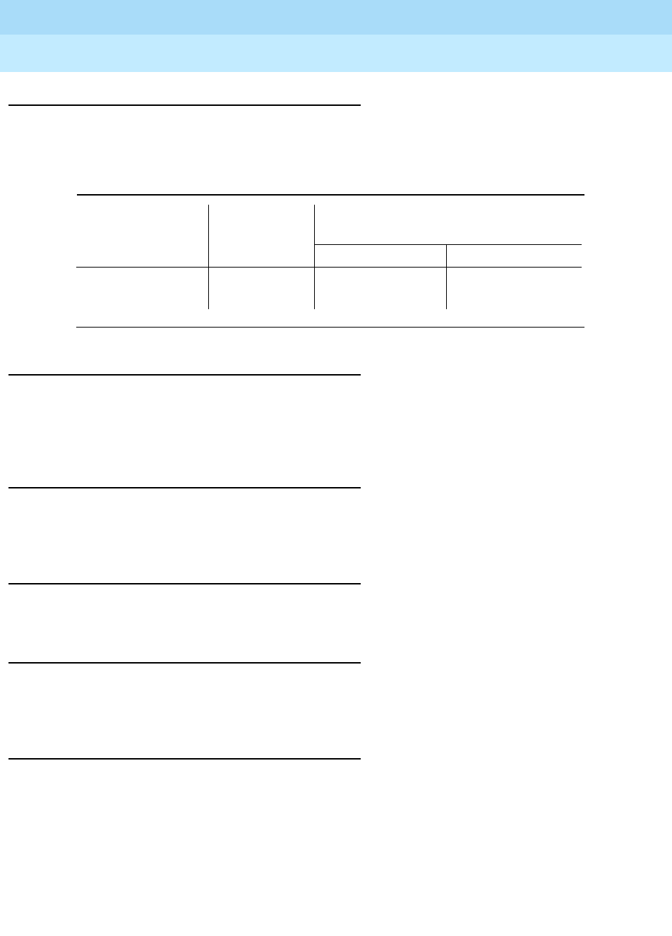
DEFINITYEnterpriseCommunicationsServerandSystem75andSystem85
Terminals and Adjuncts Reference
555-015-201 Issue 11
December 1999
The 7200 Series Voice Terminals
9-5The 7203H Voice Terminal
9
Distance Limitations
The maximum allowable distances of a 7203H voice terminal from the DEFINITY
G2 and System 85 cabinet are shown in the following table.
Power Requirements
The 7203H voice terminal is powered by the tip and ring leads. If the 7203H is
equipped with any adjunct, auxiliary power will be required for the adjunct. Refer
to the Adjunct Power section earlier in this manual.
Power Failure Operation
The 7203H voice terminal cannot be used as an emergency station during power
failure transfer conditions.
FCC Registration
The 7203H voice terminal is not FCC registered.
Hearing Aid Compatible
The 7203H voice terminal is compatible with the inductively coupled hearing aids
prescribed by the FCC.
7203H Equipment PECs
The 7203H voice terminal and optional components were ordered with the
following PECs:
■Basic 7203H Voice Terminal — 3182-16H/CLR
■Handset cord (12 feet) — 2725-01L COL09
■Line cord (14 feet, silver) — 2725-07N COL18
■Line cord (25 feet, silver) — 2725-07S COL18
Table 9-1. Distance Limitations for the 7203H Voice Terminal
System Port Board
Nominal Maximum Range in Feet
(Meters)
24 AWG 26 AWG
DEFINITY G2 and
System 85 SN224 3,000 (914) 2,300 (700)

DEFINITYEnterpriseCommunicationsServerandSystem75andSystem85
Terminals and Adjuncts Reference
555-015-201 Issue 11
December 1999
The 7200 Series Voice Terminals
9-6The 7203H Voice Terminal
9
Adjuncts
One of the following adjuncts can be used with this voice terminal:
■S101A Speakerphone
■S201A Speakerphone
■500A Headset Adapter and a standard headset
Additional Documents
The following documents contain additional information relating to the 7203H
voice terminal:
■
System 85 7203H Voice Terminal User’s Guide
, 555-102-709
■
DEFINITY Generic 1 and Generic 2, System 75, and System 85 Terminals
and Adjuncts Installation and Test
, 555-015-104
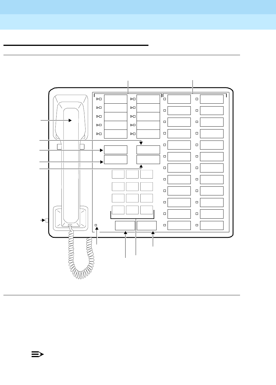
DEFINITYEnterpriseCommunicationsServerandSystem75andSystem85
Terminals and Adjuncts Reference
555-015-201 Issue 11
December 1999
The 7200 Series Voice Terminals
9-7The 7205H Voice Terminal
9
The 7205H Voice Terminal
Figure 9-2. The 7205H Voice Terminal
The 7205H is a multi-appearance hybrid voice terminal which provides six buttons
for fixed features, 10 buttons for line appearances or one-touch feature activation,
and 24 feature-only buttons. It requires 3-pair wiring for operation. One wire pair is
used for analog voice, while the other two pairs are used for digital control and
signaling.
NOTE:
The 7205H voice terminal was discontinued in March 1988.
Handset
123
456
789
ABC DEF
MNOJKLGHI
PRS TUV WXY
*
O#
Oper
Conference
Drop
Transfer
Hold
10 Call Appearance/
Message
Disconnect
Dial Pad
Message
Hold Button
Transfer
Conference
Drop Button
Volume
Control
(on left
Light Disconnect Button
Button
Feature Buttons
side)
Button
Recall
Recall
Button
24 Feature Buttons

DEFINITYEnterpriseCommunicationsServerandSystem75andSystem85
Terminals and Adjuncts Reference
555-015-201 Issue 11
December 1999
The 7200 Series Voice Terminals
9-8The 7205H Voice Terminal
9
Applications
The7205HvoiceterminalcanbeusedwithSystem85andtheDEFINITY
Communications System Generic 2. However, on a DEFINITY G2, this voice
terminal can only be used on a traditional module and the SN224 circuit pack.
This voice terminal is suitable for managers, executive secretaries, office support
personnel, and others who do not need data capabilities.
Physical Description
Dimensions
NOTE:
The following dimensions are approximate.
Width = 10-1/4 inches
Depth (front to back) = 8-3/4 inches
Height (maximum with handset in place) = 5-1/2 inches
Thickness of housing = 1-1/2 inches
Features
Six Fixed Feature Buttons
■RECALL button
■DISCONNECT button
■CONFERENCE button
■DROP button
■TRANSFER button
■HOLD button
Message Light
The green Message light goes on when a message is left for the user. It goes off
when the user retrieves the message.
Call Appearance/Feature Buttons
The 7205H voice terminal has 10 call appearance/feature buttons. Adjacent to
each button is a pair of red and green indicator lights.

DEFINITYEnterpriseCommunicationsServerandSystem75andSystem85
Terminals and Adjuncts Reference
555-015-201 Issue 11
December 1999
The 7200 Series Voice Terminals
9-9The 7205H Voice Terminal
9
Feature-Only Buttons
The 7205H voice terminal has 24 feature-only buttons.
Other Physical Features
Handset
The 7205H voice terminal is equipped with an R-type handset.
Dial pad
The 7205H voice terminal has a 12-button touch-tone dial pad.
Jacks
The 7205H voice terminal housing contains three jacks. The handset cord jack is
just under the left side of the housing. (The handset contains a jack for the other
end of the handset cord.) The line jack is on the bottom center of the housing. The
modular speakerphone/handset jack is located on the bottom of the set.
Cords
Two cords are supplied with the 7205H voice terminal: a coiled 7-foot modular
handset cord and a 7-foot modular line cord. Optional longer cords are available:
a 12-foot handset cord, and 14-foot and 25-foot line cords.
Ringing
The 7205H voice terminal has electronic tone ringing. The volume control is on
the left side of the housing.
Mounting Options
The 7205H voice terminal comes equipped with a nonadjustable desk stand. An
optional wall mounting kit can be ordered.
Color Options
The 7205H voice terminal was available in various colors; however, maintenance
replacements will be black only.
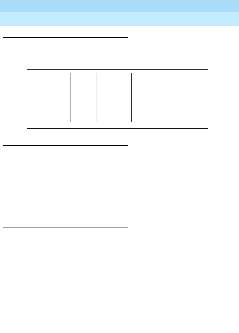
DEFINITYEnterpriseCommunicationsServerandSystem75andSystem85
Terminals and Adjuncts Reference
555-015-201 Issue 11
December 1999
The 7200 Series Voice Terminals
9-10The 7205H Voice Terminal
9
Distance Limitations
The maximum allowable distances of a 7205H voice terminal from the System 85
and the DEFINITY G2 cabinet are shown in the following table.
Power Requirements
The 7205H voice terminal is powered by the tip and ring leads. If the 7205H is
equipped with the S101A speakerphone or the 500A headset adapter, auxiliary
power will be required for the adjunct. Refer to the Adjunct Power section earlier
in this manual.
The C201A call coverage module attaches to the top of the voice terminal, and the
F201A function key module attaches to the right side. These optional modules use
the same phantom power from the switch (through the digital pairs) that also
powers the 7205H voice terminal. This impacts the distance allowed from the
switch.
Power Failure Operation
The 7205H voice terminal cannot be used as an emergency station during power
failure transfer conditions.
FCC Registration
The 7205H voice terminal is not FCC registered.
Hearing Aid Compatible
The 7205H voice terminal is compatible with the inductively coupled hearing aids
prescribed by the FCC.
Table 9-2. Distance Limitations for the 7205H Voice Terminal
System
Port
Board
Number of
Adjuncts
Nominal Maximum Range in
Feet (Meters)
24 AWG 26 AWG
DEFINITY G2
and System 85 SN224 0 3,000 (915)
1,750 (533)
1,000 (305)
2,300 (700)
1,100 (335)
750 (288)
1
2

DEFINITYEnterpriseCommunicationsServerandSystem75andSystem85
Terminals and Adjuncts Reference
555-015-201 Issue 11
December 1999
The 7200 Series Voice Terminals
9-11The 7205H Voice Terminal
9
7205H Equipment PECs
The 7205H voice terminal and optional components were ordered with the
following PECs:
■Basic 7205H Voice Terminal — 3183-40H/CLR
■Handset cord (12 feet) — 2725-01L COL09
■Line cord (14 feet, silver) — 2725-07N COL18
■Line cord (25 feet, silver) — 2725-07S COL18
Adjuncts
The following adjuncts can be used with this voice terminal:
■S101A Speakerphone or 500A Headset Adapter and a standard headset
■C201A Call Coverage Module
■F201A Function Key Module
■S201A Speakerphone
Additional Documents
The following documents contain additional information relating to the 7205H
voice terminal:
■
System 85 7205H Voice Terminal User’s Guide
, 555-102-709
■
DEFINITY Generic 1 and Generic 2, System 75, and System 85 Terminals
and Adjuncts Installation and Test
, 555-015-104

DEFINITYEnterpriseCommunicationsServerandSystem75andSystem85
Terminals and Adjuncts Reference
555-015-201 Issue 11
December 1999
The 7200 Series Voice Terminals
9-12The 7205H Voice Terminal
9

The 7300 Series Voice Terminals
10-1
10
DEFINITYEnterpriseCommunicationsServerandSystem75andSystem85
Terminals and Adjuncts Reference
555-015-201 Issue 11
December 1999
10
The 7300 Series Voice Terminals
This section describes the following 7300 Series voice terminals:
■7303S voice terminal
■7305S voice terminal
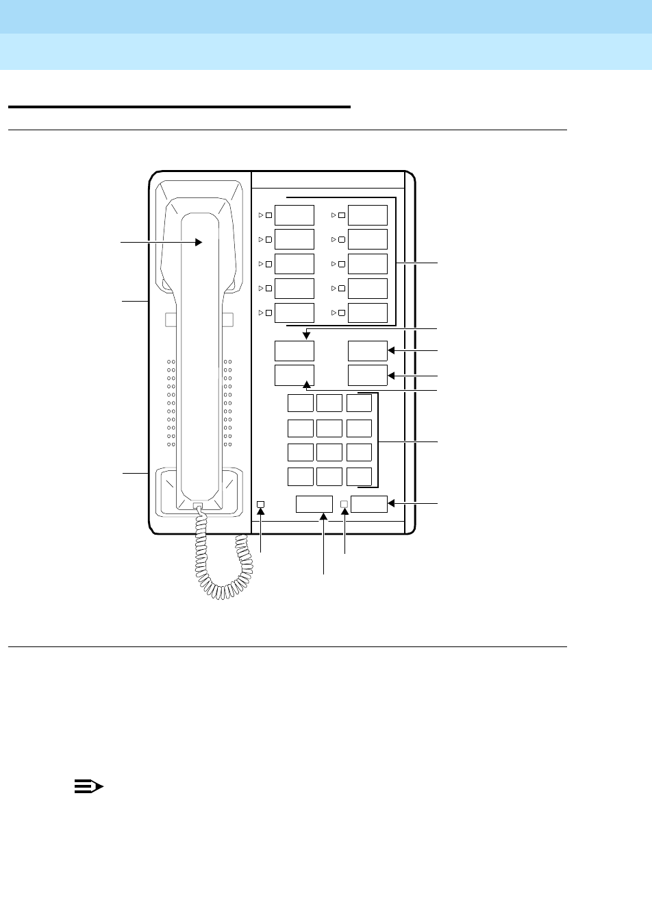
DEFINITYEnterpriseCommunicationsServerandSystem75andSystem85
Terminals and Adjuncts Reference
555-015-201 Issue 11
December 1999
The 7300 Series Voice Terminals
10-2The 7303S Voice Terminal
10
The 7303S Voice Terminal
Figure 10-1. The 7303S Voice Terminal
The 7303S is a multi-appearance hybrid voice terminal which provides access to
10 line appearances or selected programmable features. The 7303S voice
terminal is also equipped with six fixed feature buttons. It requires 3-pair wiring for
operation. One wire pair is used for analog voice, while the other two pairs are
used for digital control and signaling.
NOTE:
The 7303S voice terminal was discontinued in July 1990.
Message
123
456
789
ABC DEF
MNOJKLGHI
PRS TUV WXY
*
O#
OPER
Dial Pad
Volume
Call Appearance/
Transfer Button
Hold Button
Drop Button
Message
Conference
Drop
Transfer
Hold
Recall Speaker
Control
(on left side)
Feature Buttons
Speaker
Light
Speaker
Button
Conference Button
Light
Recall
Button
Self-Test Switch
(on left side
of base)
Handset

DEFINITYEnterpriseCommunicationsServerandSystem75andSystem85
Terminals and Adjuncts Reference
555-015-201 Issue 11
December 1999
The 7300 Series Voice Terminals
10-3The 7303S Voice Terminal
10
Applications
The 7303S voice terminal can be used with the DEFINITY Communications
System Generic 1,Generic 2, and Generic 3, the DEFINITY ECS, System 75 and
System 85 (R2 only). This voice terminal is suitable for managers, executive
secretaries, office support personnel, and others who do not need data
capabilities.
Physical Description
Dimensions
NOTE:
The following dimensions are approximate.
Width = 7 inches
Depth (front to back) = 8-3/4 inches
Height (maximum with handset in place) = 5-1/2 inches
Thickness of housing = 1-1/2 inches
Features
Six Fixed Feature Buttons
■RECALL button
■SPEAKER button
■CONFERENCE button
■DROP button
■TRANSFER button
■HOLD button
Message Light
The green Message light goes on when a message is left for the user. It goes off
when the user retrieves the message.
Call Appearance/Feature Buttons
The 7303S voice terminal has 10 call appearance/feature buttons. Adjacent to
each button is a pair of red and green indicator lights.

DEFINITYEnterpriseCommunicationsServerandSystem75andSystem85
Terminals and Adjuncts Reference
555-015-201 Issue 11
December 1999
The 7300 Series Voice Terminals
10-4The 7303S Voice Terminal
10
Self Test
The 7303S voice terminal is equipped with a self-test for its buttons and tone
ringer. The self-test switch is located on the left side of the base.
Loudspeaker
The 7303S voice terminal has a built-in listen only loudspeaker. The volume
control for the speaker is the same control used for the tone ringer volume. It is
located on the left side of the housing.
Other Physical Features
Handset
The 7303S voice terminal is equipped with an R-type handset.
Dial pad
The 7303S voice terminal has a 12-button touch-tone dial pad.
Jacks
The 7303S voice terminal housing contains three jacks. The handset cord jack is
just under the left side of the housing. (The handset contains a jack for the other
end of the handset cord.) The line jack is on the bottom center of the housing. The
modular speakerphone/handset jack is located on the bottom of the set.
Cords
Two cords are supplied with the 7303S voice terminal: a coiled 7-foot modular
handset cord and a 7-foot modular line cord. Optional longer cords are available:
a 12-foot handset cord, and 14-foot and 25-foot line cords.
Ringing
The 7303S voice terminal has electronic tone ringing. The volume control is on
the left side of the housing.
Mounting Options
The 7303S voice terminal comes equipped with a nonadjustable desk stand. An
optional wall mounting kit can be ordered.
Color Options
The 7303S Voice Terminal was available in various colors; however, maintenance
replacements are black or misty cream only.
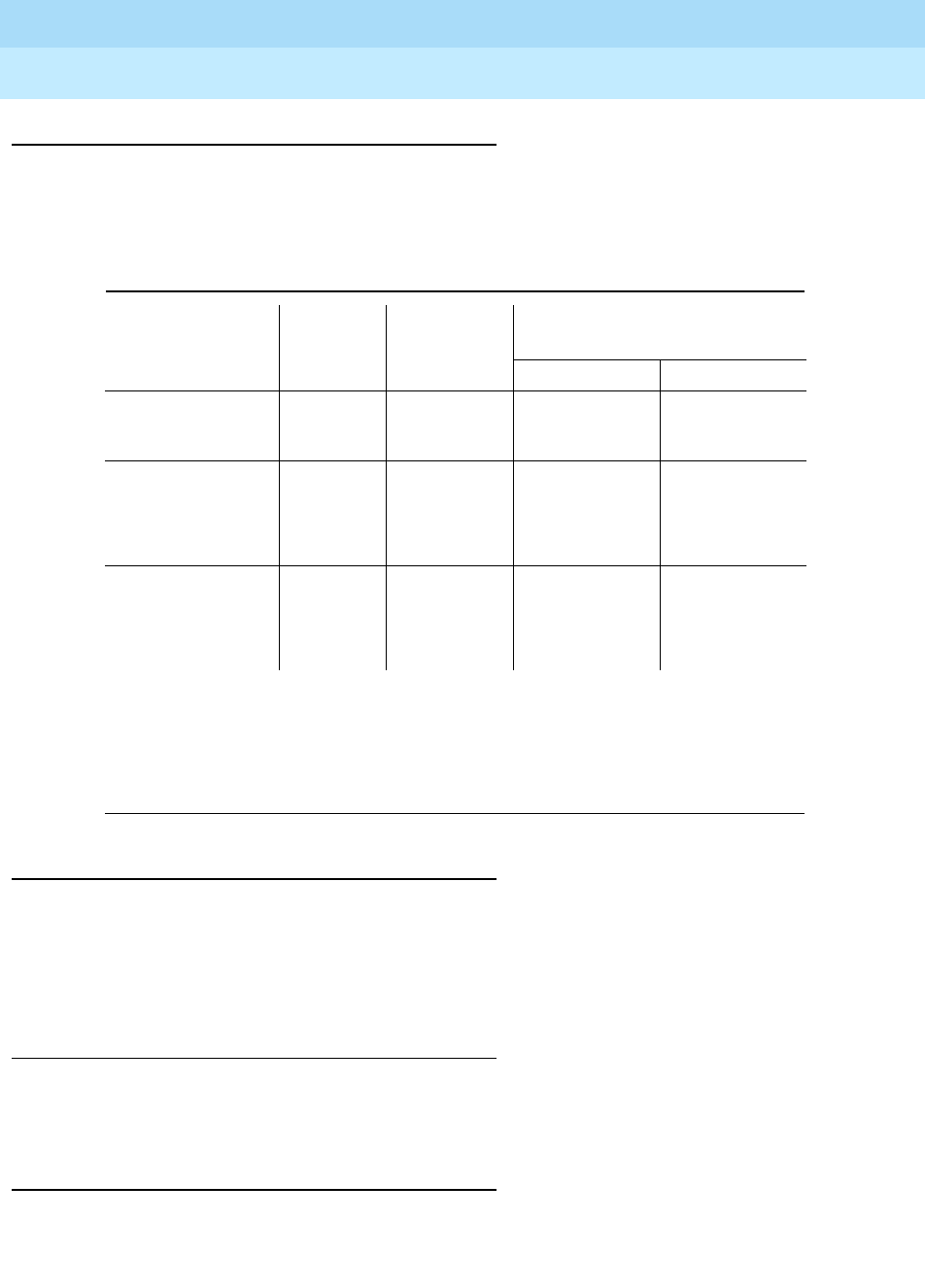
DEFINITYEnterpriseCommunicationsServerandSystem75andSystem85
Terminals and Adjuncts Reference
555-015-201 Issue 11
December 1999
The 7300 Series Voice Terminals
10-5The 7303S Voice Terminal
10
Distance Limitations
The maximum allowable distances of a 7303S voice terminal from the DEFINITY
G1, G2, and G3, DEFINITY ECS, System 75, or System 85 cabinet are shown in
the table below.
Note:
Range may be extended to 2,000 feet (610m) for 24- or 26-AWG wire by adding local
-48 volt DC power in the satellite closet. Power supplies such as the 346A or 329A may be
connected to the fourth pair from the terminals to obtain the increased range. These power
supplies must be within 250 feet of the terminals.
Power Requirements
The 7303S voice terminal is powered by the tip and ring leads.If the 7303S is
equipped with an adjunct, it is powered by the same power source. This impacts
the maximum nominal cabling distance. The range may be extended by adding
a -48 volt DC power source in the satellite closet.
Power Failure Operation
The 7303S voice terminal cannot be used as an emergency station during power
failure transfer conditions.
FCC Registration
The 7303S voice terminal is not FCC registered.
Table 10-1. Distance Limitations for the 7303S Voice Terminal
System
Port
Board
Number of
Adjuncts
Nominal Maximum Range in
Feet (Meters) (See Note)
24 AWG 26 AWG
System 85 ANN17B 0 1,700 (519) 1,000 (305)
1 1,000 (305) 650 (198)
DEFINITY G2 ANN17B 0 1,700 (519) 1,000 (305)
1 1,000 (305) 650 (198)
TN762B – 1,000 (305) 750 (229)
DEFINITY G1
and G3,
DEFINITY ECS,
and System 75
TN762 – 1,000 (305) 750 (229)

DEFINITYEnterpriseCommunicationsServerandSystem75andSystem85
Terminals and Adjuncts Reference
555-015-201 Issue 11
December 1999
The 7300 Series Voice Terminals
10-6The 7303S Voice Terminal
10
Hearing Aid Compatible
The 7303S voice terminal is compatible with the inductively coupled hearing aids
prescribed by the FCC.
7303S Equipment PECs
The 7303S voice terminal and optional components were ordered with the
following PECs:
■Basic 7303S Voice Terminal — 3176-16S/CLR
■Handset cord (12 feet — 2725-01L COL09
■Line cord (14 feet, silver) — 2725-07N COL18
■Line cord (25 feet, silver) — 2725-07S COL18
Adjuncts
One of the following adjuncts can be used with this voice terminal:
■S102A Speakerphone
■S202A Speakerphone
■502A Headset Adapter and a standard headset
Additional Documents
The following documents contain additional information relating to the 7303S
voice terminal:
■
DEFINITY Generic 2, System 85 7303S Voice Terminal User’s Guide
,
555-103-707
■
DEFINITY Generic 1, System 75 7303S Voice Terminal User’s Guide
,
555-200-706
■
DEFINITY Generic 1 and Generic 2, System 75, and System 85 Terminals
and Adjuncts Installation and Test
, 555-015-104
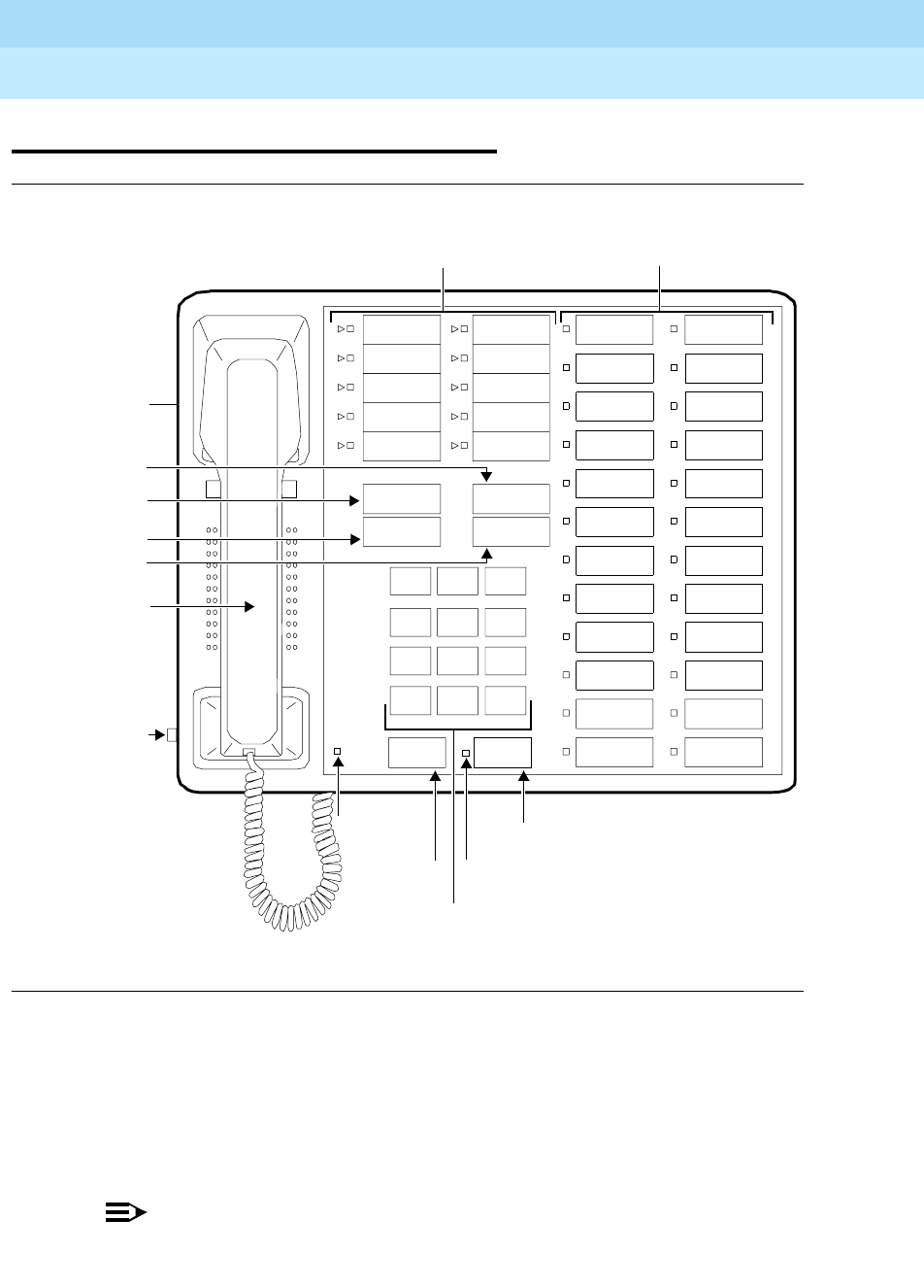
DEFINITYEnterpriseCommunicationsServerandSystem75andSystem85
Terminals and Adjuncts Reference
555-015-201 Issue 11
December 1999
The 7300 Series Voice Terminals
10-7The 7305S Voice Terminal
10
The 7305S Voice Terminal
Figure 10-2. The 7305S Voice Terminal
The 7305S voice terminal is a multi-appearance hybrid voice terminal which
provides access to 10 line appearances. The 10 line appearance buttons can also
be used as programmable feature buttons. The 7305S voice terminal is also
equipped with 24 programmable feature buttons and six fixed feature buttons. It
requires 3-pair wiring for operation. One wire pair is used for analog voice, while
the other two pairs are used for digital control and signaling.
NOTE:
The 7305S voice terminal was discontinued in July 1990.
Handset
123
456
789
ABC DEF
MNOJKLGHI
PRS TUV WXY
*
O#
Oper
Conference
Drop
Transfer
Hold
10 Call Appearance/
Message
Speaker
Dial Pad
Message
Speaker Light
Hold Button
Transfer
Conference
Drop Button
Volume
Control
(on left
Light Speaker Button
Button
Feature Buttons
side)
Button
Recall
Self-Test Switch
(on left side
of base)
Recall
Button
24 Feature Buttons

DEFINITYEnterpriseCommunicationsServerandSystem75andSystem85
Terminals and Adjuncts Reference
555-015-201 Issue 11
December 1999
The 7300 Series Voice Terminals
10-8The 7305S Voice Terminal
10
Applications
The 7305S voice terminal can be used with the DEFINITY Communications
System Generic 1, Generic 2, and Generic 3, the DEFINITY ECS, System 75, and
System 85 (R2V2 or higher). This voice terminal is suitable for managers,
executive secretaries, office support personnel, sales support people, and others
who do not need data capabilities.
Physical Description
Dimensions
NOTE:
The following dimensions are approximate.
Width = 10-1/4 inches
Depth (front to back) = 8-3/4 inches
Height (maximum with handset in place) = 6-1/4 inches
Thickness of housing = 1-1/2 inches
Features
Six Fixed Feature Buttons
■RECALL button
■SPEAKER button
■CONFERENCE button
■DROP button
■TRANSFER button
■HOLD button
Message Light
The green Message light goes on when a message is left for the user. It goes off
when the user retrieves the message.
Call Appearance/Feature Buttons
The 7305S voice terminal has 10 call appearance/feature buttons. Adjacent to
each button is pair of red and green indicator lights.

DEFINITYEnterpriseCommunicationsServerandSystem75andSystem85
Terminals and Adjuncts Reference
555-015-201 Issue 11
December 1999
The 7300 Series Voice Terminals
10-9The 7305S Voice Terminal
10
Feature-Only Buttons
The 7305S voice terminal has 24 feature-only buttons. Adjacent to each button is
a green (status) indicator light.
Self-Test
The 7305S voice terminal is equipped with a self-test for its buttons and tone
ringer. The self-test switch is located on the left side of the base.
Loudspeaker
The 7305S voice terminal has a built-in listen only loudspeaker. The volume
control for the speaker is the same control used for the tone ringer volume. It is
located on the left side of the housing.
Other Physical Features
Handset
The 7305S voice terminal is equipped with an R-type handset.
Dial pad
The 7305S voice terminal has a 12-button touch-tone dial pad.
Jacks
The 7305S voice terminal housing contains three jacks. The handset cord jack is
just under the left side of the housing. (The handset contains a jack for the other
end of the handset cord.) The line jack is on the bottom center of the housing. The
modular speakerphone/handset jack is located on the bottom of the set.
Cords
Two cords are supplied with the 7305S voice terminal: a coiled 7-foot modular
handset cord and a 7-foot modular line cord. Optional longer cords are available:
a 12-foot handset cord, and 14-foot and 25-foot line cords.
Ringing
The 7305S voice terminal has electronic tone ringing. The volume control is on
the left side of the housing.
Mounting Options
The 7305S voice terminal comes equipped with a adjustable desk stand. An
optional wall-mounting kit can be ordered.
Color Options
The 7305S voice terminal was available in black and misty cream.
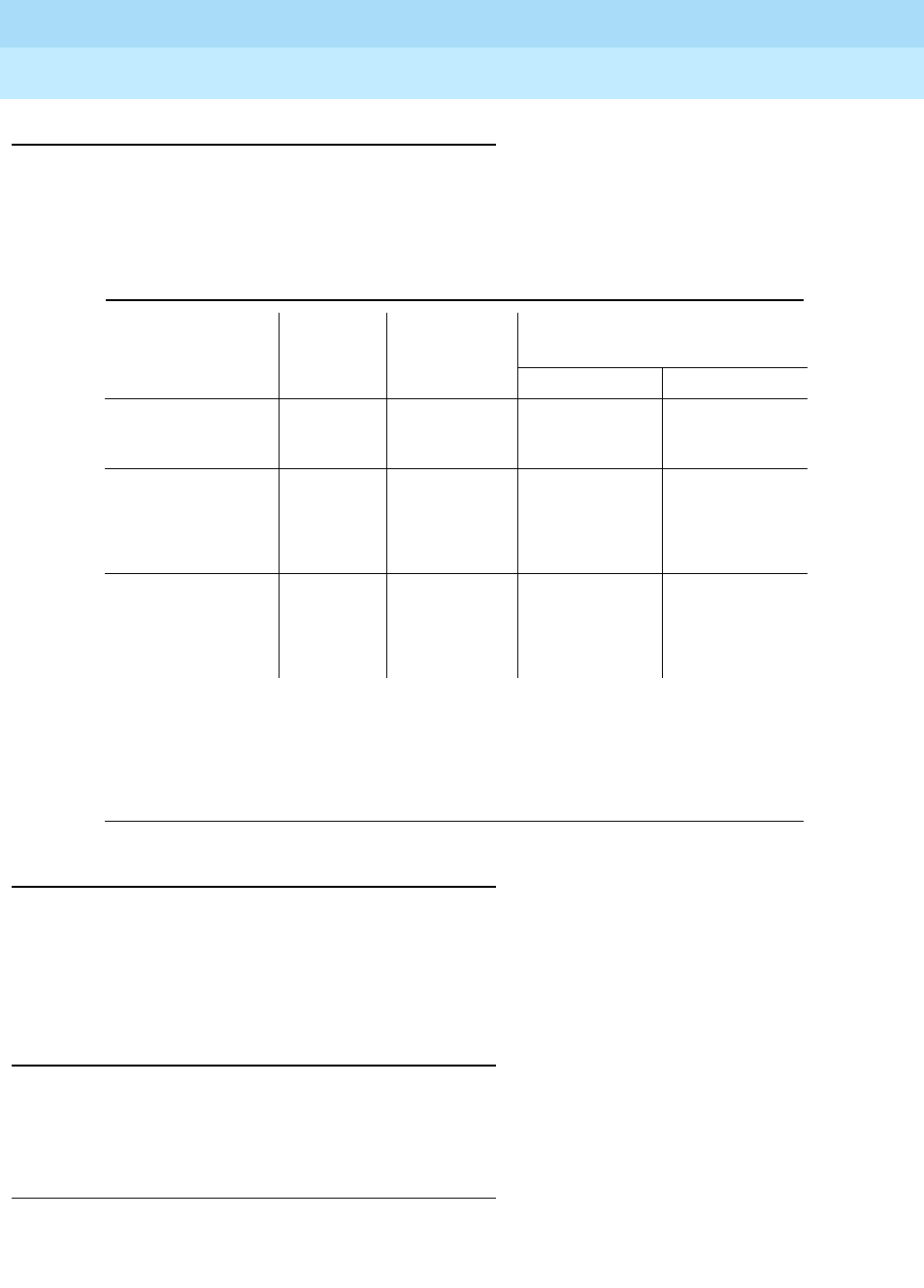
DEFINITYEnterpriseCommunicationsServerandSystem75andSystem85
Terminals and Adjuncts Reference
555-015-201 Issue 11
December 1999
The 7300 Series Voice Terminals
10-10The 7305S Voice Terminal
10
Distance Limitations
The maximum allowable distances of a 7303S from the DEFINITY G1, G2, and
G3, the DEFINITY Enterprise Communications System (ECS), System 75, or
System 85 cabinet are shown in the table below.
NOTE:
Range may be extended to 2,000 feet (610m) for 24- or 26-AWG wire by adding local -48
volt DC power in the satellite closet. Power supplies such as the 346A or 329A may be
connected to the fourth pair from the terminals to obtain the increased range. These power
supplies must be within 250 feet of the terminals.
Power Requirements
The 7305S voice terminal is powered by the tip and ring leads. If the 7305S voice
terminal is equipped with the S202A or S102A speakerphone or the 500A headset
adapter, auxiliary power will be required for the adjunct. Refer to the Adjunct
Power section earlier in this manual.
Power Failure Operation
The 7305S voice terminal cannot be used as an emergency station during power
failure transfer conditions.
FCC Registration
The 7305S voice terminal is not FCC registered.
Table 10-2. Distance Limitations for the 7305S Voice Terminal
System
Port
Board
Number of
Adjuncts
Nominal Maximum Range in
Feet (Meters) (See Note)
24 AWG 26 AWG
System 85 ANN17B 0 1,000 (305) 650 (198)
1 700 (213) 450 (137)
DEFINITY G2 ANN17B 0 1,000 (305) 650 (198)
1 700 (213) 450 (137)
TN762B – 1,000 (305) 750 (229)
DEFINITY G1
and G3,
DEFINITY ECS,
and System 85
TN762 – 1,000 (305) 750 (229)

DEFINITYEnterpriseCommunicationsServerandSystem75andSystem85
Terminals and Adjuncts Reference
555-015-201 Issue 11
December 1999
The 7300 Series Voice Terminals
10-11The 7305S Voice Terminal
10
Hearing Aid Compatible
The 7305S voice terminal is compatible with the inductively coupled hearing aids
prescribed by the FCC.
7305S Equipment PECs
The 7305S voice terminal and optional components were ordered with the
following PECs:
■Basic 7305S Voice Terminal (black) — 3177-40SA/CLR
■Handset cord (12 feet) — 2725-01L COL09
■Line cord (14 feet, silver) — 2725-07N COL18
■Line cord (25 feet, silver) — 2725-07S COL18
Adjuncts
One of the following adjuncts can be used with this voice terminal:
■S102A Speakerphone
■502A Headset Adapter and a standard headset
■S202A Speakerphone
Additional Documents
The following documents contain additional information relating to the 7305S
voice terminal:
■
System 85 7305S Voice Terminal User’s Guide
, 555-103-707
■
System 75 7305S Voice Terminal User’s Guide
, 555-200-706
■
DEFINITY Generic 1 and Generic 2, System 75, and System 85 Terminals
and Adjuncts Installation and Test
, 555-015-104

DEFINITYEnterpriseCommunicationsServerandSystem75andSystem85
Terminals and Adjuncts Reference
555-015-201 Issue 11
December 1999
The 7300 Series Voice Terminals
10-12The 7305S Voice Terminal
10

The 7400 Series Voice Terminals
11-1
11
DEFINITYEnterpriseCommunicationsServerandSystem75andSystem85
Terminals and Adjuncts Reference
555-015-201 Issue 11
December 1999
11
The 7400 Series Voice Terminals
The following 7400 Series voice terminals are described in this section:
■7401D and 7401 Plus voice terminals
■7402 Plus voice terminal
■7403D voice terminal
■7404D voice terminal
■7405D voice terminal
■7406D, 7406BIS, and 7406 Plus voice terminals
■7407D, Enhanced 7407D, and 7407 Plus voice terminals
■7410D and 7410 Plus voice terminals
■7434D voice terminal
■7444 voice terminal
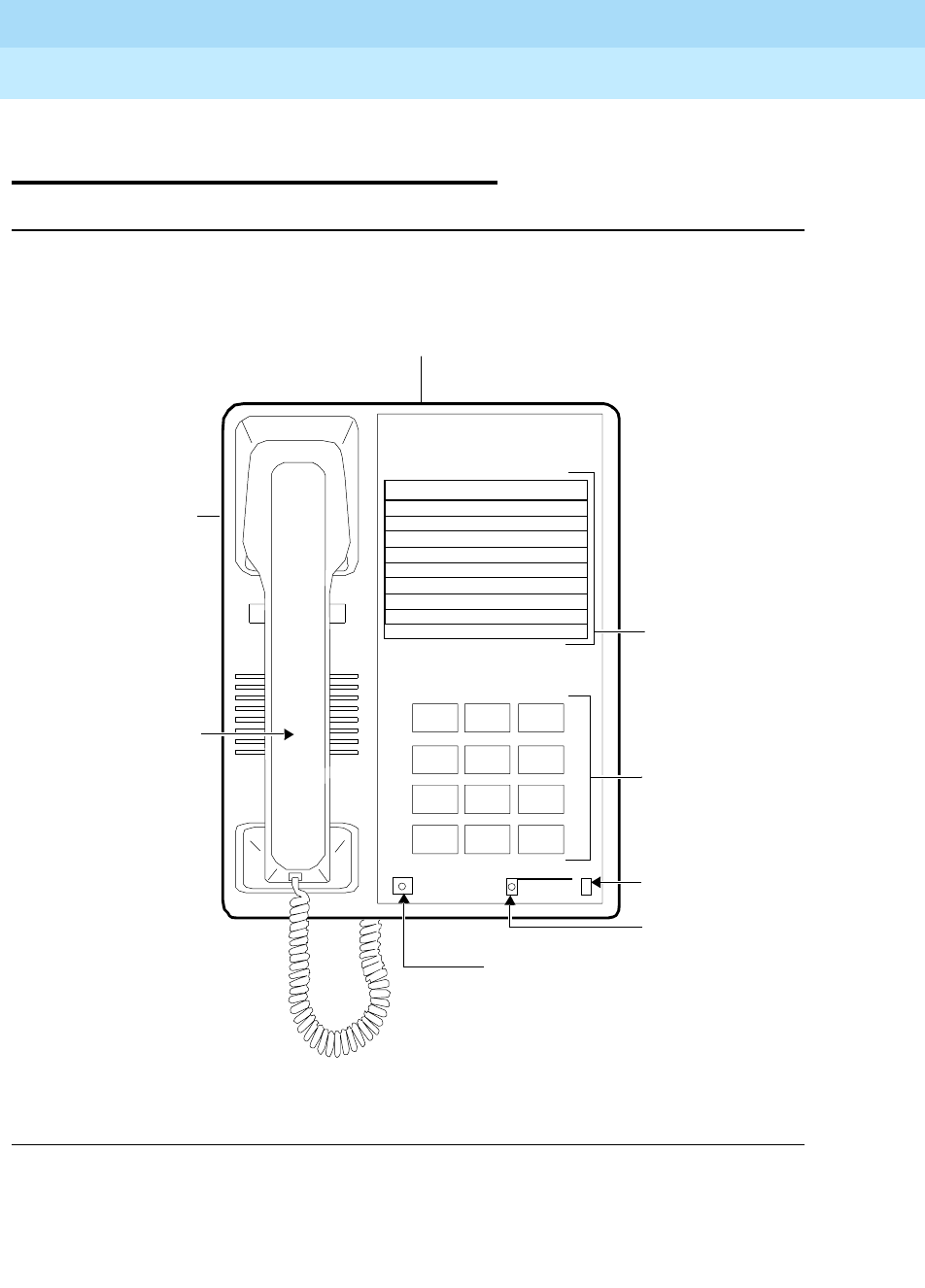
DEFINITYEnterpriseCommunicationsServerandSystem75andSystem85
Terminals and Adjuncts Reference
555-015-201 Issue 11
December 1999
The 7400 Series Voice Terminals
11-2The 7401D and 7401 Plus Voice Terminals
11
The 7401D and 7401 Plus Voice
Terminals
Figure 11-1. The 7401 Plus (7401D02A) Voice Terminal
Dial Pad
Message Light
Feature/Call
Feature Button
Message
123
456
789
ABC DEF
MNOJKLGHI
PQRS TUV WXYZ
*
O#
Oper
7401 Plus
Feature
Activity Light
Feature Directory
Feature Directory
F1
F2
F3
F4
F5
F6
F7
F8
F*
Speakerphone/
Headset Adapter Jack
(on back of voice
terminal for 7401 Plus only)
Ringer
Volume Control
(on the 7401D,
control is on left side;
on the 7401 Plus,
Handset
control is on back
of voice terminal)

DEFINITYEnterpriseCommunicationsServerandSystem75andSystem85
Terminals and Adjuncts Reference
555-015-201 Issue 11
December 1999
The 7400 Series Voice Terminals
11-3The 7401D and 7401 Plus Voice Terminals
11
The 7401D (7401D01A) and the 7401 Plus (7401D02A, the newest 7401 set) are
both single appearance digital voice terminals which have no call appearance
buttons or lights, but have two virtual call appearances (refer to the section below
titled Special Operational Characteristics). The user answers a call by going
off-hook. The second appearance is primarily used with the Conference and
Transfer features. However, it can be used to originate an outgoing call or receive
a second incoming call. Depending on how the 7401D or the 7401 Plus voice
terminal is administered, the second call appearance may be restricted to
incoming priority calls and outgoing calls only.
NOTE:
The 7401D01A is no longer being manufactured. The 7401D02A (7401
Plus) was discontinued January, 1995.
Applications
The 7401D (7401D01A) and the 7401 Plus (7401D02A) voice terminals can be
used with the DEFINITY Communications System Generic 1, Generic 2, and
Generic 3, the DEFINITY ECS, System 75, and System 85. These voice terminals
are especially suitable for general office workers with low call volumes,
manufacturing, warehousing, guard and/or reception areas, or office desks.
The 7401D and 7401 Plus voice terminals can also provide simultaneous voice
and data communications with the 7400B Data Module. PC platform products can
also be useful in providing voice capabilities since these screen-based products
can greatly enhance the telephone capabilities of these basic voice terminals.
Special Operational Characteristics
The 7401D (7401D01A) and 7401 Plus (7401D02A) do not have traditional call
appearance buttons with indicators. To the user, these voice terminals appear to
be single call appearance sets. However, there are two
virtual
call appearances
with
virtual
in-use and
virtual
status indicators. That is, to the PBX, the 7401D and
7401 Plus voice terminals appear to be a two call appearance set. These call
appearances are necessary to provide the Conference, Transfer, and Hold
features.

DEFINITYEnterpriseCommunicationsServerandSystem75andSystem85
Terminals and Adjuncts Reference
555-015-201 Issue 11
December 1999
The 7400 Series Voice Terminals
11-4The 7401D and 7401 Plus Voice Terminals
11
The Automatic Line Management (ALM) feature of the 7401D or 7401 Plus voice
terminal automatically selects one of the two
virtual
call appearances when the
user goes off-hook either by the user’s lifting the handset (on the 7401D or the
7401 Plus voice terminal) or turning on the optional speakerphone adjunct (on the
7401 Plus voice terminal). ALM follows a hierarchical algorithm. From the user’s
point of view, the hierarchical order of actions which could take place is:
1. If either of the status lights of the virtual call appearances is flashing when
the user takes the telephone off-hook, the voice terminal will always pick-up
the “ringing” call. If both virtual call appearances are in the flashing state,
the voice terminal will select the call that was ringing for the longer period
of time.
2. If neither of the status lights is flashing, but one is winking or fluttering when
the telephone goes off-hook, the voice terminal will automatically “un-hold”
the held call. If both virtual call appearances are in the held state, the voice
terminal will select the call that was on hold for the longer period of time.
3. If neither of the status lights is flashing, winking, or fluttering, but one is
steady when the voice terminal goes off-hook, the voice terminal will
automatically bridge on to the busy appearance. If both virtual call
appearances are in the steady state, the voice terminal will choose the first
virtual call appearance. (A call appearance can be in the busy state due to
another party answering the call. This can occur in conjunction with such
features as coverage, bridging or pickup.)
4. Otherwise, no special action is taken; the voice terminal will pick up an idle
virtual call appearance as determined by the PBX.
Physical Features
Dimensions
NOTE:
The dimensions described here for the 7401D and 7401 Plus voice
terminals are approximate.
Width = 6-3/8 inches
Depth (front to back) = 8-3/4 inches
Height (maximum with handset in place) = 5-1/2 inches
Thickness of housing = 1-1/2 inches

DEFINITYEnterpriseCommunicationsServerandSystem75andSystem85
Terminals and Adjuncts Reference
555-015-201 Issue 11
December 1999
The 7400 Series Voice Terminals
11-5The 7401D and 7401 Plus Voice Terminals
11
Features
The Feature Button
The FEATURE button allows the dial pad to serve as 12 feature buttons without
indicators:
■Four standard fixed feature buttons: Conference, Transfer, Drop, Hold
■The Select Ring feature
■Seven administrable feature buttons used with the FEATURE button
Feature/Call Activity Light
The green Feature/Call Activity light goes on steadily when the user presses the
FEATURE button. This light flutters when there is an incoming call, when a call is
put on hold, or when a call has been answered by another bridged extension. It
flutters intermittently when Select Ring is used.
Feature Directory
The 7401D (7401D01A) voice terminal has a reversible feature directory card.
One side lists fixed features and leaves spaces for features assigned by the
system manager; the other side lists fixed and recommended features.
The 7401 Plus (7401D02A) voice terminal has a one-sided feature directory card.
The directory lists fixed features and has spaces for features assigned by the
system manager.
Message Light
The Message light goes on when a message is left for the user. It goes off when
the user retrieves the message. On the 7401D voice terminal, the Message light is
green; on the 7401 Plus voice terminal, the Message light is red.
Other Physical Features
Handset
The 7401D and 7401 Plus voice terminals are equipped with an R-type handset.
Dial pad
The 7401D and the 7401 Plus voice terminals are equipped with a 12-button
touch-tone dial pad. On the 7401 Plus voice terminal, the letters “Q” and “Z” have
been added to the appropriate dial pad keys for directory access, and the “5”
button on the dial pad has raised bars for visually-impaired users.

DEFINITYEnterpriseCommunicationsServerandSystem75andSystem85
Terminals and Adjuncts Reference
555-015-201 Issue 11
December 1999
The 7400 Series Voice Terminals
11-6The 7401D and 7401 Plus Voice Terminals
11
Jacks
The 7401D and 7401 Plus voice terminals’ housing has a Handset cord jack. (On
the 7401D voice terminal, this jack is located just under the center front edge of
the housing; on the 7401 Plus the Handset cord jack is located on the back of the
housing near the front/center.) Both voice terminals have a Line jack located on
the back of the housing.
The 7401 Plus (7401D02A) voice terminal also has a Speakerphone/headset
adapter jack to which the user can connect adjunct equipment.
Cords
Two cords are supplied with the 7401D (7401D01A) and the 7401 Plus
(7401D02A) voice terminal: a coiled 9-foot handset cord and a 7-foot line cord.
Optional longer cords are available: a 12-foot handset cord, and 14-foot and
25-foot line cords.
Ringing
The 7401D and 7401 Plus voice terminals have electronic tone ringing. With the
Select Ring feature, the user can choose any one of eight different ringing
patterns.
The 7401D (7401D01A) voice terminal has a volume control on the left side of the
housing.
The 7401 Plus (7401D02A) voice terminal has a volume control for the tone ringer
on the back of the voice terminal, along the left edge.
Mounting Options
The 7401D and 7401 Plus voice terminals come equipped with both a
nonadjustable desk stand and a wall mounting bracket.
Color Options
The 7401D and 7401 Plus voice terminals are available in black and misty cream.
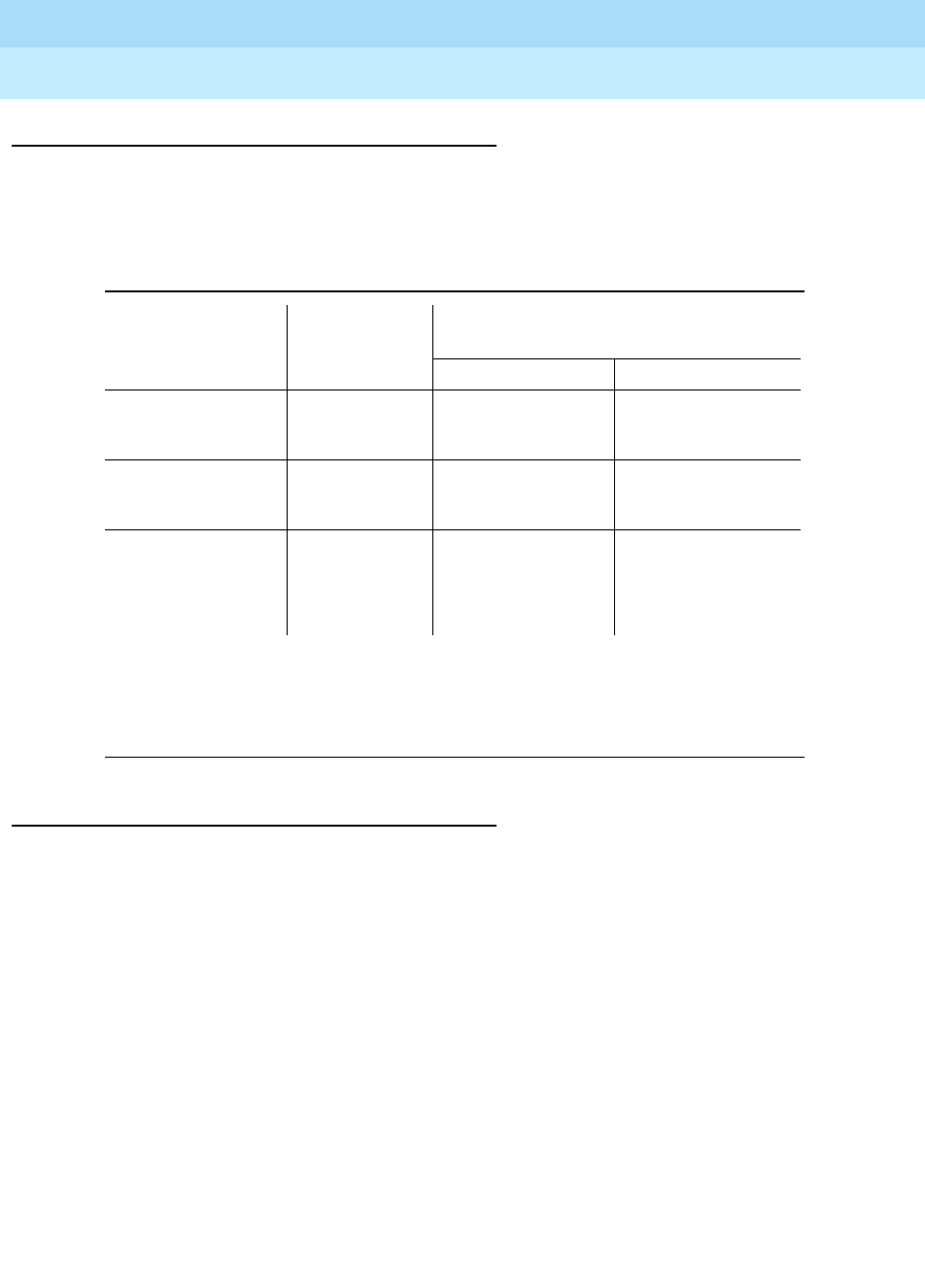
DEFINITYEnterpriseCommunicationsServerandSystem75andSystem85
Terminals and Adjuncts Reference
555-015-201 Issue 11
December 1999
The 7400 Series Voice Terminals
11-7The 7401D and 7401 Plus Voice Terminals
11
Distance Limitations
The maximum allowable distances of a 7401D or a 7401 Plus voice terminal from
the DEFINITY ECS G1, G2, and G3, DEFINITY ECS, System 75, or System 85
cabinet are shown in the following table.
Note:
These ranges can be extended to 5,000 feet (1524 m) for 24 AWG wire and 4,000 feet
(1219 m) for 26 AWG wire with the use of a Data Link Protector. Refer to the Exposed Port
Protection section earlier in this manual.
Power Requirements
The 7401D and 7401 Plus voice terminals receive power from the system and do
not require any external power supply. Additional external power is required when
the 7401 Plus voice terminal is equipped with any adjuncts, such as an external
speakerphone. Refer to the Adjunct Power section earlier in this manual.
Table 11-1. Distance Limitations for the 7401D and 7401 Plus Voice Terminals
System Port Board
Nominal Maximum Range in Feet
(Meters) (See Note)
24 AWG 26 AWG
System 85 SN270B
TN754
3,400 (1,034)
3,400 (1,034)
2,200 (671)
2,200 (671)
DEFINITY G2 SN270B
TN754
3,400 (1,034)
3,400 (1,034)
2,200 (671)
2,200 (671)
DEFINITY G1 and
G3, DEFINITY
ECS, and System
75
TN754 3,400 (1,034) 2,200 (671)
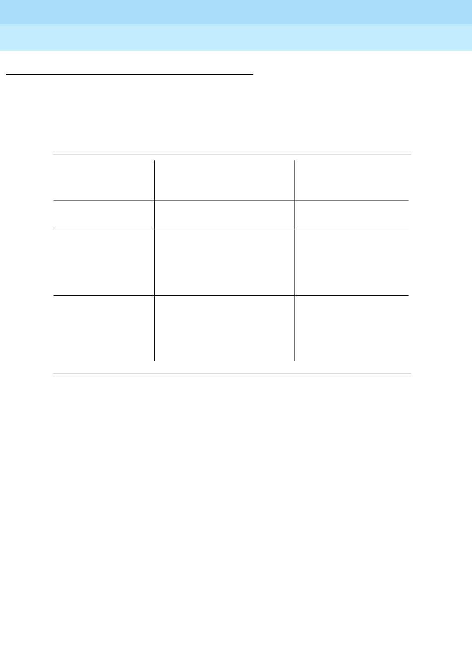
DEFINITYEnterpriseCommunicationsServerandSystem75andSystem85
Terminals and Adjuncts Reference
555-015-201 Issue 11
December 1999
The 7400 Series Voice Terminals
11-8The 7401D and 7401 Plus Voice Terminals
11
Switch Administration
Aliasing
The 7401 voice terminals must be aliased in the following way:
Table 11-2. Administering the 7401D and 7401 Plus Voice Terminals
If this type of voice
terminal: Is connected to this system:
The voice terminal
must be administered
as:
7401D
7401 Plus System 75, R1V1, V2, V3
System 85, R2V1, V2, V3 a 7403D voice terminal
7401D DEFINITY G1 and G3, and
DEFINITY ECS
System 85, R2V4 or above
DEFINITY G2
itself
7401 Plus DEFINITY G1 and G3, and
DEFINITY ECS
System 85, R2V4 or above
DEFINITY G2
a 7401D voice terminal

DEFINITYEnterpriseCommunicationsServerandSystem75andSystem85
Terminals and Adjuncts Reference
555-015-201 Issue 11
December 1999
The 7400 Series Voice Terminals
11-9The 7401D and 7401 Plus Voice Terminals
11
Button Numbering
The 7401 Plus (7401D02A) voice terminal can be administered in the same
manner as the 7401D (7401D01A) voice terminal. Both types of voice terminals
have 12 possible voice features; however, only seven of these features can be
administered on the voice terminal (F1 through F7 on the Feature Directory). The
remaining five features are fixed (F8, F9, F0, F#, and F* on the Feature Directory):
F8 Conference
F9 Transfer
F0 Drop
F# Hold
F* Select Ring
The following button diagrams of the 7401D and 7401 Plus voice terminals will
help you administer both of these voice terminals connected to a System 75, a
DEFINITY G1 and G3, or a DEFINITY ECS, and to a System 85 or a
DEFINITY G2.
Figures 11-2 and 11-3 show button numbering for both the 7401D and the 7401
Plus voice terminals.
NOTE:
Although these figures show the 7401 Plus set, the administration of the two
types of voice terminals is the same.
If you need more information, refer to
DEFINITY Communications System
Generic 3 Implementation
, 555-230-653, and
DEFINITY Communications System
Generic 2 Administration of Features and Hardware
, 555-104-507.
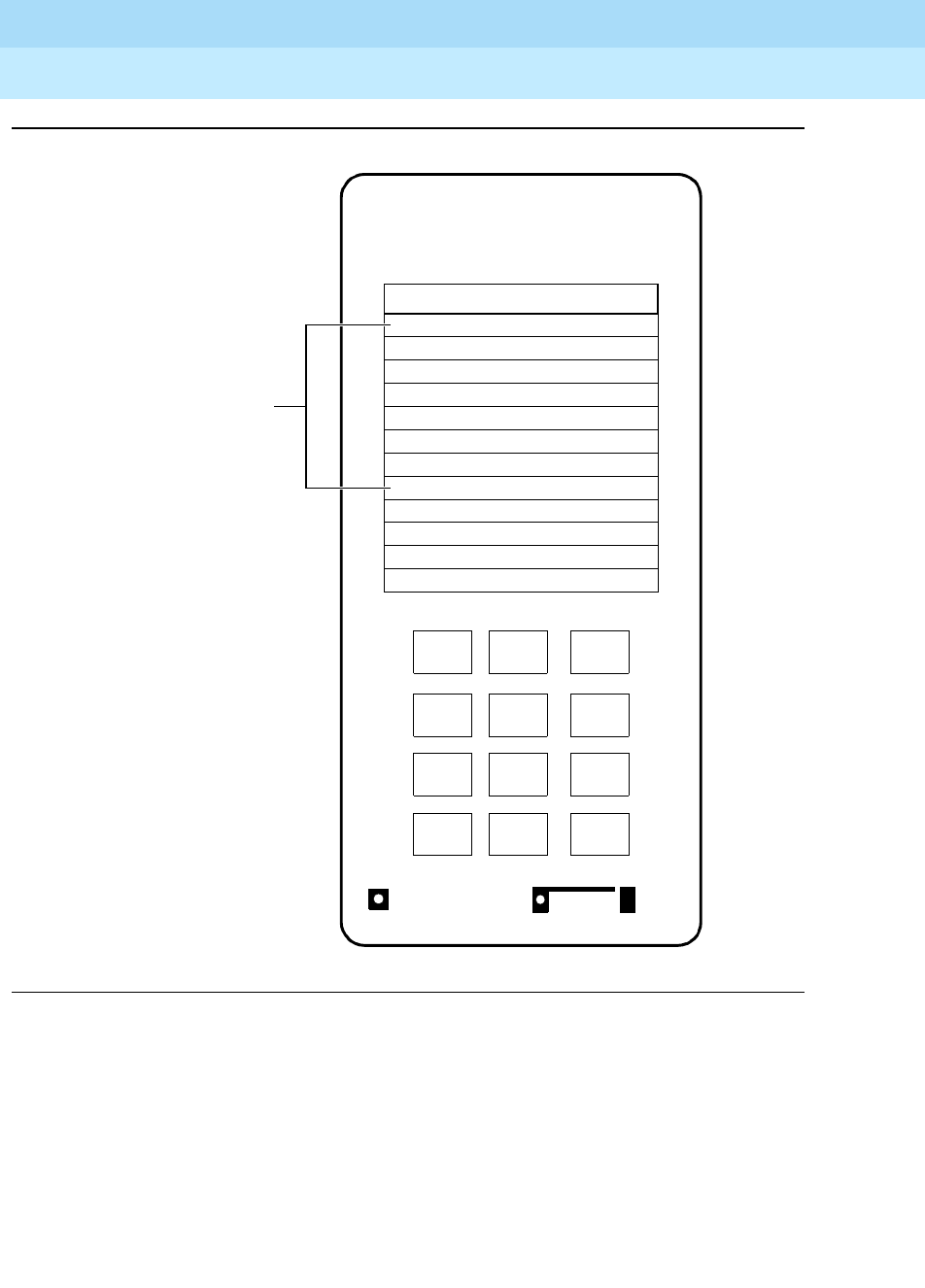
DEFINITYEnterpriseCommunicationsServerandSystem75andSystem85
Terminals and Adjuncts Reference
555-015-201 Issue 11
December 1999
The 7400 Series Voice Terminals
11-10The 7401D and 7401 Plus Voice Terminals
11
Figure 11-2. Button Number for Administering the 7401D and 7401 Plus Voice Terminals
Connected to a System 75, DEFINITY G1 and G3, or a DEFINITY ECS
Message
123
456
789
ABC DEF
MNOJKLGHI
PQRS TUV WXYZ
*
O#
Oper
Feature
Feature Directory
F1
F2
F3
F4
F5
F6
F7
F8 Conference
F9 Transfer
F0 Drop
F# Hold
F* Select Ring
Buttons 1 and 2 are
line appearances.
Buttons 3-9 are F1-F7.
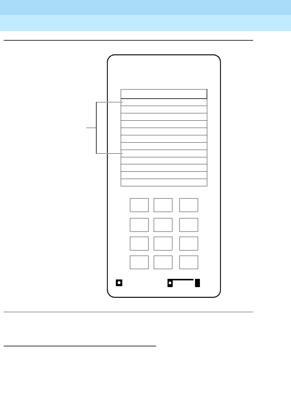
DEFINITYEnterpriseCommunicationsServerandSystem75andSystem85
Terminals and Adjuncts Reference
555-015-201 Issue 11
December 1999
The 7400 Series Voice Terminals
11-11The 7401D and 7401 Plus Voice Terminals
11
Figure 11-3. Button Numbering for Administering the 7401D and 7401 Plus Voice
Terminals Connected to a System 85 or a DEFINITY G2
Power Failure Operation
The 7401D and 7401 Plus voice terminals cannot be used as an emergency
station during power failure transfer conditions.
Message
123
456
789
ABC DEF
MNOJKLGHI
PQRS TUV WXYZ
*
O#
Oper
Feature
Feature Directory
F1
F2
F3
F4
F5
F6
F7
F8 Conference
F9 Transfer
F0 Drop
F# Hold
F* Select Ring
Buttons 1 and 2 are
the Hold Button and
the Message Light.
Buttons 3 and 4 are
line appearances.
Buttons 5-11 are
F1 through F7.

DEFINITYEnterpriseCommunicationsServerandSystem75andSystem85
Terminals and Adjuncts Reference
555-015-201 Issue 11
December 1999
The 7400 Series Voice Terminals
11-12The 7401D and 7401 Plus Voice Terminals
11
FCC Registration
These voice terminals are FCC-registered along with the switch (as a system), but
do not have a separate FCC registration label.
UL and CSA Approval
These voice terminals have been tested and have met the Underwriters
Laboratories (UL) Standards UL 1459 and have also met the Canadian Standards
Association (CSA) Standards CSA-C22.2 No.225-M90.
Hearing Aid Compatible
These voice terminals are compatible with the inductively coupled hearing aids
prescribed by the FCC.
7401D Equipment PECs and Comcodes
The 7401D (7401D01A) voice terminals and components can be ordered with
these Price Element Codes (PECs) and Comcodes:
■Basic 7401D Voice Terminal
PEC: 3184-CDT (Black=COL09; Misty Cream=COL22)
Comcode: Black=105353056; Misty Cream=105269153
■Handset
Comcode: Black=105157291; Misty Cream=105158885
■Handset cord (9 feet)
Comcode: Black=105635429; Misty Cream=105635437
■Handset cord (12 feet)
PEC: 2725-01L (Black=COL09; Misty Cream=COL22)
Comcode: Black=102401445; Misty Cream=104211339
■Line cord (7 feet, silver)
Comcode: 105304646
■Line cord (14 feet, silver)
PEC: 2725-07N (COL18)
Comcode: 103786802
■Line cord (25 feet, silver)
PEC: 2725-07S (COL18)
Comcode: 103786828
■Faceplate and tab
Comcode: Black=846209161; Misty Cream=846209179

DEFINITYEnterpriseCommunicationsServerandSystem75andSystem85
Terminals and Adjuncts Reference
555-015-201 Issue 11
December 1999
The 7400 Series Voice Terminals
11-13The 7401D and 7401 Plus Voice Terminals
11
■Button designation cards
(Package of 50)
PEC: 31841 (Black=COL09; Misty Cream=COL22)
Comcode: Black=846051225; Misty Cream=846051183
■Desk stand/Wall mount assembly
Comcode: 846028546
7401 Plus Equipment with PECs and Comcodes
The following 7401 Plus (7401D02A) voice terminal and components can be
ordered with the following PECs and Comcodes:
■Basic 7401 Plus Voice Terminal
PEC: 3184-PLS (Black=COL18; Misty Cream=COL22)
Comcode: Black=106224454; Misty Cream=106224462
■Handset
Comcode: Black=105519086; Misty Cream=105520787
■Handset cord (9 feet)
Comcode: Black=105635429; Misty Cream=105635437
■Handset cord (12 feet)
PEC: 2725-01L (Black=COL09; Misty Cream=COL22)
Comcode: Black=102401445; Misty Cream=104211339
■Line cord (7 feet)
Comcode: 103786778
■Line cord (14 feet, silver)
PEC: 2725-07N (COL18)
Comcode: 103786828
■Line cord (25 feet, silver)
PEC: 2725-07S (COL18)
Comcode: 103786802
■Faceplate
(Package of 50)
PEC: 31846
Comcode: Black=846551141 Misty Cream=846551406
■Button designation card
PEC: 31844 (Package of 50 cards)
Single Sheets, Comcode: 846521656
Pack of 50, Comcode: 846521664
Tractor Feed, 200 Sheets, Comcode: 846551672
Tractor Feed, 500 Sheets, Comcode: 846551680
■Desk stand/Wall mount assembly
Comcode: 846028546

DEFINITYEnterpriseCommunicationsServerandSystem75andSystem85
Terminals and Adjuncts Reference
555-015-201 Issue 11
December 1999
The 7400 Series Voice Terminals
11-14The 7401D and 7401 Plus Voice Terminals
11
Adjuncts
One of the following adjuncts can be used with the 7401D (7401D01A) voice
terminal:
■R6 Amplifier Handset (PEC: 3152-002)
■R8 Noisy Location Handset (PEC: 3152-003)
■7400B Data Module
The following adjuncts can be used with the 7401 Plus (7401D02A) voice
terminal:
■S101A Speakerphone (no longer orderable)
■S201A Speakerphone
■CS201A Speakerphone
■7400B Data Module
■500A Headset Adapter (and a standard headset; see “Headsets” below)
■R6 Amplifier Handset (PEC: 3152-002)
■R8 Noisy Location Handset (PEC: 3152-003)
■R2H Standard Handset (PEC: 3152-006)
■Shoulder Rest
Headsets
A list of compatible headsets, consisting of both modular and plug prong base
units and selection of headpieces, appears in “Headset Adapters” in the Adjuncts
section later in this manual.

DEFINITYEnterpriseCommunicationsServerandSystem75andSystem85
Terminals and Adjuncts Reference
555-015-201 Issue 11
December 1999
The 7400 Series Voice Terminals
11-15The 7401D and 7401 Plus Voice Terminals
11
Additional Documents
The following documents contain additional information relating to the 7401D and
7401 Plus voice terminals: (Use the 9 digit number listed after each document to
order the book from the BCS Publications Center for Lucent Technologies.)
■
7401D Voice Terminal Installation Instructions
, 555-015-106
■S
ystem 75 7401D Voice Terminal User’s Guide
, 555-200-727
■
DEFINITY Communications System Generic 1 7401D Voice Terminal
User’s Guide
, 555-204-727
■
DEFINITY Communications System Generic 2 and System 85 7401D
Voice Terminal User’s Guide
, 555-104-712
■
DEFINITY Communications System Generic 1 and System 75 7401 Plus
Voice Terminal User’s Guide
, 555-204-740
■
DEFINITY Communications System Generic 2 and System 85 7401 Plus
Voice Terminal User’s Guide
, 555-104-740
The following document is shipped with every 7401 Plus voice terminal:
■
7401 Plus and 7410 Plus Voice Terminals Installation Instructions
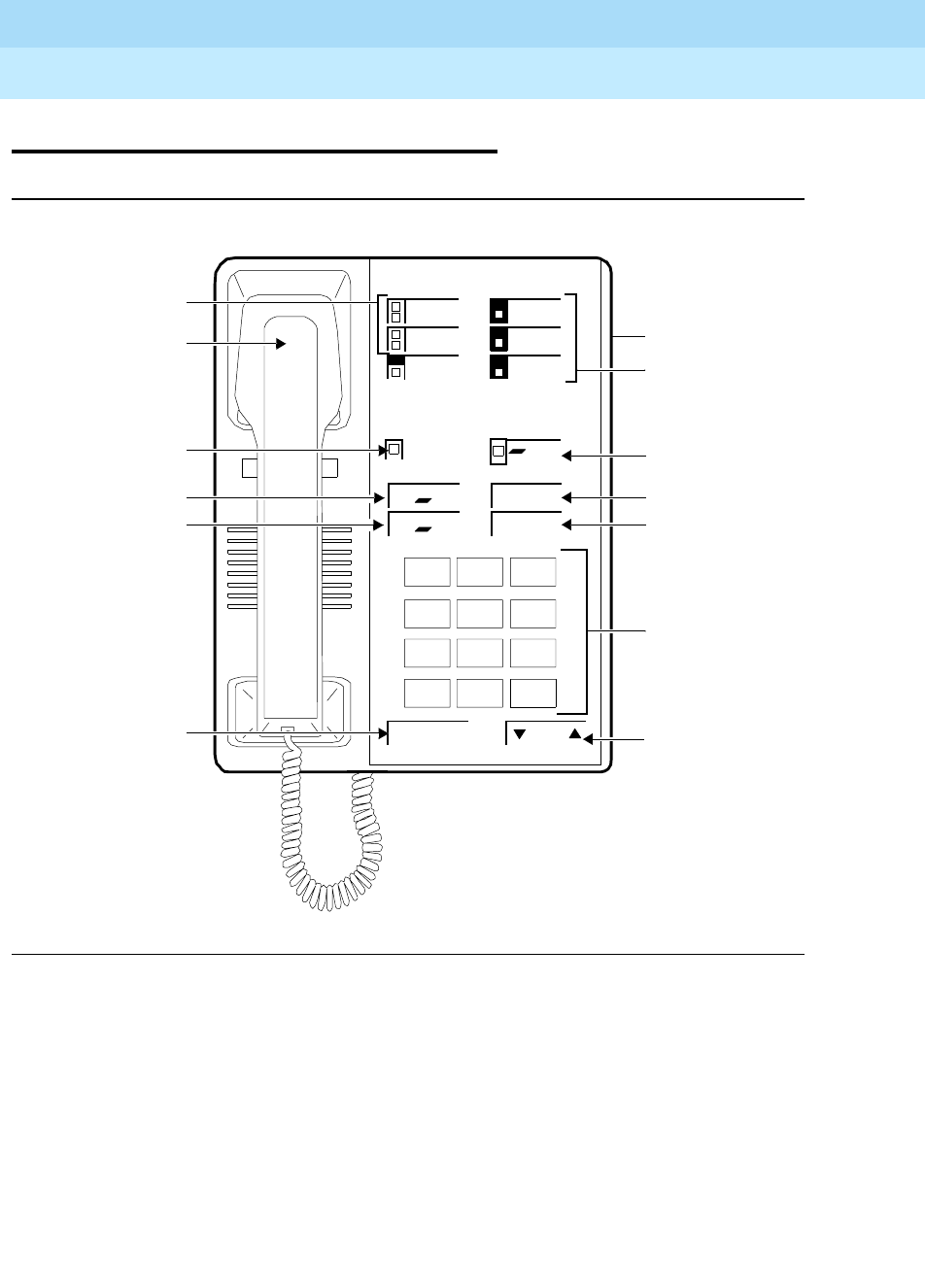
DEFINITYEnterpriseCommunicationsServerandSystem75andSystem85
Terminals and Adjuncts Reference
555-015-201 Issue 11
December 1999
The 7400 Series Voice Terminals
11-16The 7402 Plus Voice Terminal
11
The 7402 Plus Voice Terminal
Figure 11-4. The 7402 Plus Voice Terminal
Dial Pad
Handset
Transfer Button
Message Light
Drop/Test Button
Volume
123
456
789
ABC DEF
MNOJKLGHI
PQRS TUV WXYZ
*
O#
Oper
Conference
Drop
Transfer
Hold
Conference/Ring
Button
Hold Button
4 Feature-Only
Speaker Volume
Ring
Test
Message Select
Select Button
Speakerphone/
Headset Adapter
Jack (on back of
voice terminal)
2 Call Appearance/
Feature Buttons
Buttons
Control
Button
Speaker Button
DEFINITYEnterpriseCommunicationsServerandSystem75andSystem85
Terminals and Adjuncts Reference
555-015-201 Issue 11
December 1999
The 7400 Series Voice Terminals
11-17The 7402 Plus Voice Terminal
11
The 7402 Plus is a multi-appearance digital voice terminal with two line
appearances, four variable feature buttons, four standard fixed feature buttons
(CONFERENCE, DROP, TRANSFER, and HOLD), a SELECT button, a Message
light, a SPEAKER button for accessing a listen-only speaker, a Ringer Volume
control, and a Speakerphone/headset adapter jack on the back of the voice
terminal for connecting adjunct equipment. By pressing the SELECT button and
then the CONFERENCE/RING button, the user can choose among eight possible
programmable ringing patterns. A Self-Test feature can also be activated to test
the lights and tone ringer on the voice terminal.
NOTE:
The 7402 Plus was discontinued in January, 1995.
Applications
The 7402 Plus voice terminal can be used with the DEFINITY Communications
System Generic 1, Generic 2, and Generic 3, the DEFINITY ECS, System 75, and
System 85. This voice terminal is especially suitable for managers, executive
secretaries, and other office support personnel who require access to multiple
lines for call handling, call coverage, bridging, conferencing, and sophisticated
voice communications.
The 7402 Plus voice terminal can also provide simultaneous voice and data
communications with the 7400B Data Module. PC platform products can also be
useful in providing voice capabilities since these screen-based products can
greatly enhance the telephone capabilities of these basic voice terminals.
Physical Features
Dimensions
NOTE:
The following dimensions for the 7402 Plus voice terminal are approximate.
Width = 6-3/8 inches
Depth (front to back) = 8-3/4 inches
Height (maximum with handset in place) = 5-1/2 inches
Thickness of housing = 1-1/2 inches

DEFINITYEnterpriseCommunicationsServerandSystem75andSystem85
Terminals and Adjuncts Reference
555-015-201 Issue 11
December 1999
The 7400 Series Voice Terminals
11-18The 7402 Plus Voice Terminal
11
Features
Four Standard Fixed Feature Buttons
■CONFERENCE/RING button
■DROP/TEST button
■TRANSFER button
■HOLD button
Message Light
The red Message light goes on when a message is left for the user. It goes off
when the user retrieves the message.
Call Appearance and Feature Buttons
The 7402 Plus voice terminal has two call appearance buttons, each with a red
and green status light. The 7402 Plus also has four variable feature buttons. Each
of these feature buttons has a green status light next to it.
SELECT button
The 7402 Plus voice terminal has a SELECT button which can be used in two
ways:
■When used with the CONFERENCE/RING button, the user can select a
personalized ring from eight ringing patterns.
■When used with the DROP/TEST button, the user can initiate a self-test of
the lights and ringer on the voice terminal.
SPEAKER button
The 7402 Plus voice terminal has a SPEAKER button which allows the user to
place calls while on-hook, to monitor calls on which the user has been put on hold,
or retrieve messages without lifting the handset. However, the Speaker feature is
for listening only. In order to speak to the other party, the user must use the
handset (the speaker must be off).
VOLUME control button
When the speaker is active on the 7402 Plus voice terminal speaker, the VOLUME
control button affects the loudness of the Speaker (listen-only) feature.
At all other times (when the speaker is not being used), the VOLUME control
button affects the volume of the tone ringer.

DEFINITYEnterpriseCommunicationsServerandSystem75andSystem85
Terminals and Adjuncts Reference
555-015-201 Issue 11
December 1999
The 7400 Series Voice Terminals
11-19The 7402 Plus Voice Terminal
11
Other Physical Features
Handset
The 7402 Plus voice terminal is equipped with an R-type handset.
Dial pad
The 7402 Plus voice terminal is equipped with a 12-button touch-tone dial pad.
The letters “Q” and “Z” have been added to the appropriate dial pad keys for
directory access, and the “5” button on the dial pad has raised bars for
visually-impaired users.
Jacks
The 7402 Plus voice terminal’s housing contains three jacks. The Handset cord
jack is on the back of the housing near the front. The Line jack and the
Speakerphone/headset adapter jack on both voice terminals are on the back of
the voice terminal.
Cords
Two cords are supplied with the 7402 Plus voice terminal: a coiled 9-foot modular
handset cord and a 7-foot D8W 8-conductor modular line cord.
Optional longer cords are available: a 12-foot handset cord; 14-foot and 25-foot
line cords.
Ringing
The 7402 Plus voice terminal has electronic tone ringing. With the Personalized
Ringing feature, the user can choose any one of eight different ringing patterns.
The volume on the 7402 Plus voice terminal can be controlled with the VOLUME
“arrow” button on the front of the voice terminal.
Mounting Options
The 7402 Plus voice terminal comes equipped with a desk stand or can be
wall-mounted.
Color Options
The 7402 Plus voice terminal is available in black and misty cream.
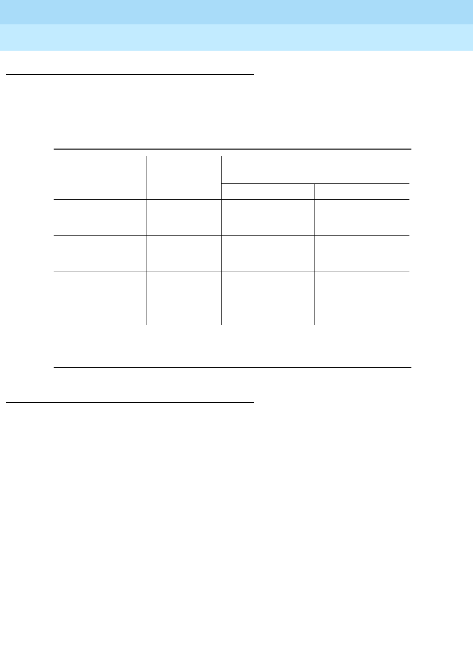
DEFINITYEnterpriseCommunicationsServerandSystem75andSystem85
Terminals and Adjuncts Reference
555-015-201 Issue 11
December 1999
The 7400 Series Voice Terminals
11-20The 7402 Plus Voice Terminal
11
Distance Limitations
The maximum allowable distances of a 7402 Plus voice terminal from the
DEFINITY G1, G2, G3, the DEFINITY ECS, System 75, or System 85 cabinet are
shown in the following table.
Note:
These ranges can be extended to 5,000 feet (1524 m) for 24 AWG wire and 4,000 feet
(1219 m) for 26 AWG wire with the use of a Data Link Protector.
Power Requirements
The 7402 Plus voice terminal receives power from the system and does not
require any external power supply. Additional external power is required when the
7402 Plus voice terminal is equipped with any adjuncts, such as an external
speakerphone.
Table 11-3. Distance Limitations for the 7402 Plus Voice Terminal
System Port Board
Nominal Maximum Range in Feet
(Meters) (See Note)
24 AWG 26 AWG
System 85 SN270B
TN754
3,400 (1,034)
3,400 (1,034)
2,200 (671)
2,200 (671)
DEFINITY G2 SN270B
TN754
3,400 (1,034)
3,400 (1,034)
2,200 (671)
2,200 (671)
DEFINITY G1 and
G3, DEFINITY
ECS, and System
75
TN754 3,400 (1,034) 2,200 (671)
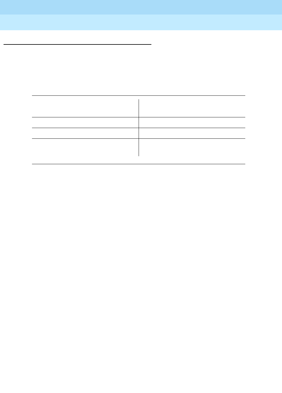
DEFINITYEnterpriseCommunicationsServerandSystem75andSystem85
Terminals and Adjuncts Reference
555-015-201 Issue 11
December 1999
The 7400 Series Voice Terminals
11-21The 7402 Plus Voice Terminal
11
Switch Administration
Aliasing
The 7402 voice terminals must be aliased in the following way:
Button Numbering
The following button diagrams of the 7402 Plus voice terminal, Figures 11-5 and
11-6, will help you administer this voice terminal when it is connected to a
System 75 or a DEFINITY G1 and G3, or a DEFINITY ECS, and to a System 85
or a DEFINITY G2.
In these figures, the button numbers on the six administrable call appearance and
feature buttons correspond to button assignments on Page 2 of the voice terminal
administration screen form.
If you need more information, refer to
DEFINITY Communications System
Generic 3 Implementation
, 555-230-653, and
DEFINITY Communications System
Generic 2 Administration of Features and Hardware
, 555-104-507.
Table 11-4. Administering the 7402 Plus Voice Terminal
If you are administering the
7402 Plus with this system: The voiced terminal, must be
administered as a:
System 75, R1V1, V2 7403D voice terminal
System 75, R1V3 7410D
DEFINITY Generic 1, 2, or 3, or a
DEFINITY ECS 7410D
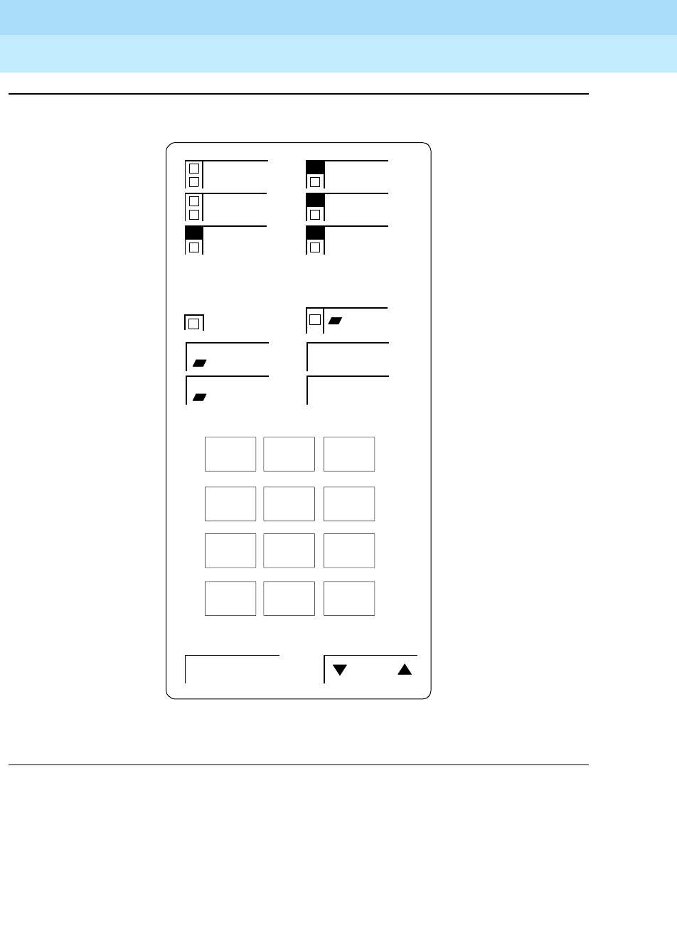
DEFINITYEnterpriseCommunicationsServerandSystem75andSystem85
Terminals and Adjuncts Reference
555-015-201 Issue 11
December 1999
The 7400 Series Voice Terminals
11-22The 7402 Plus Voice Terminal
11
Figure 11-5. Button Numbering for Administering the 7402 Plus Voice Terminal
Connected to a System 75, a DEFINITY G1 or G3, or a DEFINITY ECS
Conference
Drop
Transfer
Hold
Speaker Volume
Ring
Test
Message Select
6
7
83
1
2
123
456
789
ABC DEF
MNOJKLGHI
PQRS TUV WXYZ
*O#
Oper
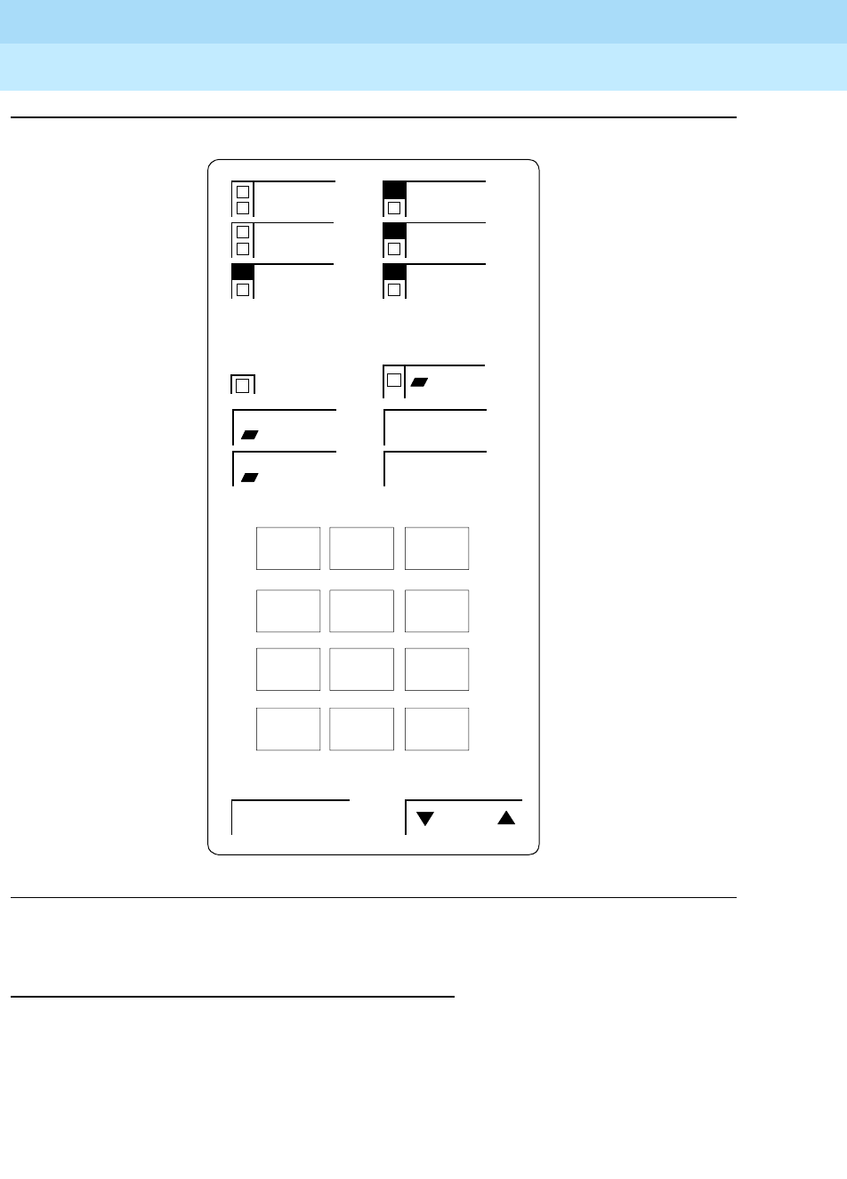
DEFINITYEnterpriseCommunicationsServerandSystem75andSystem85
Terminals and Adjuncts Reference
555-015-201 Issue 11
December 1999
The 7400 Series Voice Terminals
11-23The 7402 Plus Voice Terminal
11
Figure 11-6. Button Numbering for Administering the 7402 Plus Voice Terminal
Connected to a System 85 or a DEFINITY G2
Power Failure Operation
The 7402 Plus voice terminal cannot be used as an emergency station during
power failure transfer conditions.
Conference
Drop
Transfer
Hold
Speaker Volume
Ring
Test
Message Select
8
9
105
3
4
123
456
789
ABC DEF
MNOJKLGHI
PQRS TUV WXYZ
*O#
Oper

DEFINITYEnterpriseCommunicationsServerandSystem75andSystem85
Terminals and Adjuncts Reference
555-015-201 Issue 11
December 1999
The 7400 Series Voice Terminals
11-24The 7402 Plus Voice Terminal
11
FCC Registration
The 7402 Plus voice terminal is FCC-registered along with the switch (as a
system), but does not have a separate FCC registration label.
UL and CSA Approval
This voice terminal has been tested and has met the Underwriters Laboratories
(UL) Standards UL 1459 and has also met the Canadian Standards Association
(CSA) Standards CSA-C22.2 No.225-M90.
Hearing Aid Compatible
This voice terminal is compatible with the inductively coupled hearing aids
prescribed by the FCC.
7402 Plus Equipment PECs and Comcodes
The 7402 Plus voice terminal and components were ordered with the following
PECs and Comcodes:
■Basic 7402 Plus Voice Terminal
PEC: 3189-PLS (Black=COL09; Misty Cream=COL22)
Comcode: Black=105425185; Misty Cream=105425144
■Handset
Comcode: Black=105519086; Misty Cream=105520787
■Handset cord (9 feet)
Comcode: Black=105635429; Misty Cream=105635437
■Handset cord (12 feet)
PEC: 2725-01L (Black=COL09; Misty Cream=COL22)
Comcode: Black=102401445; Misty Cream=104211339
■Line Cord (7 feet, silver)
Comcode: 103786778
■Line cord (14 feet, silver)
PEC: 2725-07N (COL18)
Comcode: 103786802
■Line cord (25 feet, silver)
PEC: 2725-07S (COL18)
Comcode: 103786828
■Button designation card
PEC: 31866A (Package of 25 tractor feed cards)
PEC: 31890A (Package of 100 tractor feed cards)

DEFINITYEnterpriseCommunicationsServerandSystem75andSystem85
Terminals and Adjuncts Reference
555-015-201 Issue 11
December 1999
The 7400 Series Voice Terminals
11-25The 7402 Plus Voice Terminal
11
■Single sheets
Comcode: 846523892
Pack of 50 Comcode: 846523900
Tractor feed, 200 Sheets Comcode: 846551448
Tractor feed, 500 Sheets Comcode: 846551455
■Faceplate
Comcode: Black=846523876; Misty Cream=846523884
(Package of 50)
PEC: 31867 (Black=COL09; Misty Cream=COL22)
Comcode: Black=847043304, Misty Cream=847043312
■Desk stand/Wall mount assembly
Comcode: 846028546
Adjuncts
The following adjuncts can be used with this voice terminal:
■S101A Speakerphone (no longer orderable)
■S201A Speakerphone
■CS201A Speakerphone
■7400B Data Module
■500A Headset Adapter (and a standard headset; see “Headsets” below)
■R6 Amplifier Handset (PEC: 3152-002)
■R8 Noisy Location Handset (PEC: 3152-003)
■IR2H Standard Handset (PEC: 3152-019)
■Shoulder Rest
Headsets
A list of compatible headsets, consisting of both modular and plug prong base
units and selection of headpieces, appears in “Headset Adapters” in the Adjuncts
section later in this manual.

DEFINITYEnterpriseCommunicationsServerandSystem75andSystem85
Terminals and Adjuncts Reference
555-015-201 Issue 11
December 1999
The 7400 Series Voice Terminals
11-26The 7402 Plus Voice Terminal
11
Additional Documents
The following documents contain additional information relating to the 7402 Plus
voice terminal: (Use the 9-digit number listed after each document to order the
book from the BCS Publications Center for Lucent Technologies.)
■
DEFINITY Communications System Generic 1 and System 75 7402 Plus
Voice Terminal User’s Guide
, 555-230-760
■
DEFINITY Communications System Generic 2 and System 85 7402 Plus
Voice Terminal User’s Guide
, 555-104-724
The following document is shipped with every 7402 Plus voice terminal:
■
7402 Plus Voice Terminal Installation Instructions
, 555-015-140
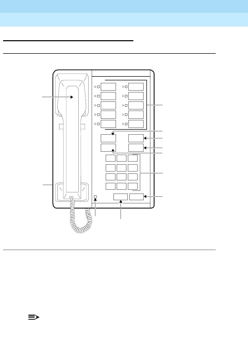
DEFINITYEnterpriseCommunicationsServerandSystem75andSystem85
Terminals and Adjuncts Reference
555-015-201 Issue 11
December 1999
The 7400 Series Voice Terminals
11-27The 7403D Voice Terminal
11
The 7403D Voice Terminal
Figure 11-7. The 7403D Voice Terminal
The 7403D is a multi-appearance digital voice terminal which has 10 buttons
available for line appearances, one-touch feature access, or Speed Dialing. The
7403D is a multi-appearance digital voice terminal which has 10 buttons available
for line appearances, one-touch feature access, or Speed Dialing. In addition, the
7403D voice terminal may be equipped with a Digital Terminal Data Module
(DTDM) which attaches to the right side and allows the connection of a EIA
RS-232C data terminal.
NOTE:
The 7403D voice terminal has been discontinued.
Message
123
456
789
ABC DEF
MNOJKLGHI
PRS TUV WXY
*
O#
OPER
Dial Pad
Call Appearance/
Transfer Button
Hold Button
Drop Button
Message
Conference
Drop
Transfer
Hold
Recall Disconnect
Feature Buttons
Light Recall
Button
Disconnect
Button
Conference Button
Volume
Control
(on left side)
Handset

DEFINITYEnterpriseCommunicationsServerandSystem75andSystem85
Terminals and Adjuncts Reference
555-015-201 Issue 11
December 1999
The 7400 Series Voice Terminals
11-28The 7403D Voice Terminal
11
Applications
The 7403D voice terminal can be used with the DEFINITY Communications
System Generic 1, Generic 2, and Generic 3, the DEFINITY ECS, System 75, and
System 85. This voice terminal is especially suitable for managers, executive
secretaries, and office support personnel. When equipped with a DTDM or 7400B,
it is also suitable for users who have data terminals.
Physical Description
Dimensions
NOTE:
The following dimensions for the 7403D voice terminal are approximate.
Width = 7 inches
Depth (front to back) = 8-3/4 inches
Height (maximum with handset in place) = 5-1/2 inches
Thickness of housing = 1-1/2 inches
Features
Six Fixed Feature Button
■RECALL button
■DISCONNECT button
■CONFERENCE button
■DROP button
■TRANSFER button
■HOLD button
Message light
The green Message light goes on when a message is left for the user. It goes off
when the user retrieves the message.
Call Appearance/Feature Buttons
The 7403D voice terminal has 10 call appearance/feature buttons. Adjacent to
each button is a red light and a green status indicator light.

DEFINITYEnterpriseCommunicationsServerandSystem75andSystem85
Terminals and Adjuncts Reference
555-015-201 Issue 11
December 1999
The 7400 Series Voice Terminals
11-29The 7403D Voice Terminal
11
Self-Test
The 7403D voice terminal is equipped with a self-test for its buttons and tone
ringer. The self-test switch is located on the left side of the base.
Other Physical Features
Handset
The 7403D voice terminal is equipped with an R-type handset.
Dial pad
The 7403D voice terminal is equipped with a 12-button touch-tone dial pad.
Jacks
The 7403D voice terminal housing contains three jacks. The handset cord jack is
just under the left side of the housing. The handset contains a jack for the handset
cord. The LINE and OTHER jacks are on the bottom center of the housing.
Cords
Two cords are supplied with the 7403D voice terminal: a coiled 7-foot modular
handset cord and a 7-foot modular line cord. Optional longer cords are available:
a 12-foot handset cord; 14-foot and 25-foot line cords.
Ringing
The 7403D voice terminal has electronic tone ringing. The volume control is on
the left side of the housing.
Mounting Options
The 7403D voice terminal comes equipped with a nonadjustable desk stand. An
optional wall mounting kit can be ordered.
Color Options
The 7403D voice terminal was available in black and misty cream.

DEFINITYEnterpriseCommunicationsServerandSystem75andSystem85
Terminals and Adjuncts Reference
555-015-201 Issue 11
December 1999
The 7400 Series Voice Terminals
11-30The 7403D Voice Terminal
11
Distance Limitations
The maximum distance the 7403D voice terminal can be located from the system
cabinet is shown in the following table.
Note:
These ranges can be extended to 5,000 feet (1524 m) for 24 AWG wire and 4,000 feet
(1219 m) for 26 AWG wire with the use of a Data Link Protector. Refer to EXPOSED PORT
PROTECTION.
Power Requirements
The 7403D voice terminal receives power from the system and does require any
external power supply. Additional power is required when the 7403D voice
terminal is equipped with a DTDM. Refer to the Adjunct Power section earlier in
this manual.
Power Failure Operation
The 7403D voice terminal cannot be used as an emergency station during power
failure transfer conditions.
FCC Registration
The 7403D voice terminal is not FCC registered.
Hearing Aid Compatible
This voice terminal is compatible with the inductively coupled hearing aids
prescribed by the FCC.
Table 11-5. Distance Limitations for the 7403D Voice Terminal
System Port Board
Nominal Maximum Range in Feet
(Meters) (See Note)
24 AWG 26 AWG
System 85 SN270B
TN754
3,400 (1,034)
3,400 (1,034)
2,200 (671)
2,200 (671)
DEFINITY G2 SN270B
TN754
3,400 (1,034)
3,400 (1,034)
2,200 (671)
2,200 (671)
DEFINITY G1 and
G3, DEFINITY
ECS, and System
75
TN754 3,400 (1,034) 2,200 (671)

DEFINITYEnterpriseCommunicationsServerandSystem75andSystem85
Terminals and Adjuncts Reference
555-015-201 Issue 11
December 1999
The 7400 Series Voice Terminals
11-31The 7403D Voice Terminal
11
7403D Equipment PECs
The 7403D voice terminal and optional components were ordered with the
following PECs:
NOTE:
The 7403D voice terminal has been discontinued, and thus it cannot be
ordered.
■Basic 7403D Voice Terminal — 3174-16D/CLR
■Basic 7403D Voice Terminal with DTDM — 3174-16D/CLR + 31745
■Handset cord (12 feet) — 2725-01L COL09
■Line cord (14 feet, silver) — 2725-07N COL18
■Line cord (25 feet, silver) — 2725-07S COL18
Adjuncts
One of the following adjuncts can be used with this voice terminal:
■S101A Speakerphone
■S201A Speakerphone (PEC 3152-007A)
■500A Headset Adapter and a standard headset (PEC 3152-001A)
■Z701A Digital Terminal Data Module
■7400B Data Module
■R6 Amplifier Handset (PEC 3152-002A)
■R8 Noisy Location Handset (PEC 3152-003A)
Additional Documents
The following documents contain additional information relating to the 7403D
voice terminal:
■
System 85 7403D Voice Terminal User’s Guide
, 555-103-709
■
System 75 7403D Voice Terminal User’s Guide
, 555-200-704
■
DEFINITY Generic 1 and Generic 2, System 75, and System 85 Terminals
and Adjuncts Installation and Test
, 555-015-104
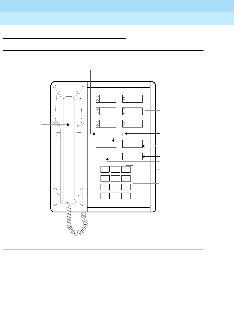
DEFINITYEnterpriseCommunicationsServerandSystem75andSystem85
Terminals and Adjuncts Reference
555-015-201 Issue 11
December 1999
The 7400 Series Voice Terminals
11-32The 7404D Voice Terminal
11
The 7404D Voice Terminal
Figure 11-8. The 7404D Voice Terminal
The 7404D is a multi-appearance digital voice terminal which provides
simultaneous voice/asynchronous data transmission. All the transmission is done
over the same two pairs of wire.
123
456
789
ABC DEF
MNOJKLGHI
PRS TUV WXY
*
O#
OPER
Dial Pad
Call Appearance/
Transfer Button
Hold Button
Drop Button
Conference
Drop
Feature Buttons
Conference Button
Volume
Control
(on left side)
Handset
Transfer
Hold
Message Light
Self-Test Switch
(on left side
of base)
Data Call in
Progress Light
Built-in
Data Module
DEFINITYEnterpriseCommunicationsServerandSystem75andSystem85
Terminals and Adjuncts Reference
555-015-201 Issue 11
December 1999
The 7400 Series Voice Terminals
11-33The 7404D Voice Terminal
11
The 7404D voice terminal can be equipped with one of two different optional
cartridges. The Z300B cartridge provides a display of voice call related and
personal service information on an attached data terminal. The Z300C cartridge
provides an interface between an NCR PC (or compatible) with the PC/PBX
Connection application program and the DEFINITY Communications System
Generic 2 or System 85.
NOTE:
The 7404D voice terminal was discontinued in February, 1989.
Applications
The 7404D voice terminal can be used with the DEFINITY Communications
System Generic 1 and Generic 2, Generic 3, the DEFINITY ECS, System 75, and
System 85. Typical applications of the 7404D voice terminal are users who have
data terminals or a PC that requires a small selection of lines and features.
Physical Description
Dimensions
NOTE:
The following dimensions for the 7404D voice terminal are approximate.
Width = 7 inches
Depth (front to back) = 8-3/4 inches
Height (maximum with handset in place) = 5-1/2 inches
Thickness of housing = 1-1/2 inches
Features
Four Fixed Feature Buttons
■CONFERENCE button
■DROP button
■TRANSFER button
■HOLD button
Message Light
The green Message light goes on when a message is left for the user. It goes off
when the user retrieves the message.

DEFINITYEnterpriseCommunicationsServerandSystem75andSystem85
Terminals and Adjuncts Reference
555-015-201 Issue 11
December 1999
The 7400 Series Voice Terminals
11-34The 7404D Voice Terminal
11
Data Light
The Data light goes on when a data call is in progress.
Call Appearance/Feature Buttons
The 7404D voice terminal has six call appearance/feature buttons. Adjacent to
each button is a pair of red and green indicator lights.
Self-Test
The 7404D voice terminal is equipped with a self-test for its buttons and tone
ringer. The self-test switch is located on the left side of the base.
Other Physical Features
Handset
The 7404D voice terminal is equipped with an R-type handset.
Dial pad
The 7404D voice terminal is equipped with a 12-button touch-tone dial pad.
Jacks
The 7404D voice terminal housing contains three jacks. The handset cord jack is
just under the left side of the housing. The handset contains a jack for the handset
cord. The LINE jack is on the rear housing. There is a EIA RS-232C receptacle on
the rear of the voice terminal that is used to connect an associated data terminal.
Cords
Three cords are supplied with the 7404D voice terminal: a coiled 7-foot modular
handset cord, 7-foot modular line cord and an AC power cord. Optional longer
cords are available: a 12-foot handset cord; 14-foot and 25-foot line cords.
Ringing
The 7404D voice terminal has electronic tone ringing with patterns that are set at
administration. The volume control is on the left side of the housing.
Mounting Options
The 7404D voice terminal comes equipped with a nonadjustable data stand.
Color Options
The 7404D voice terminal was available in black and misty cream.
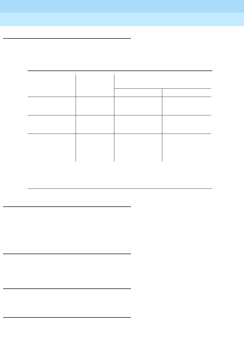
DEFINITYEnterpriseCommunicationsServerandSystem75andSystem85
Terminals and Adjuncts Reference
555-015-201 Issue 11
December 1999
The 7400 Series Voice Terminals
11-35The 7404D Voice Terminal
11
Distance Limitations
The maximum distances the 7404D voice terminal can be located from the system
cabinet is shown in the following table.
Note:
These ranges can be extended to 5,000 feet (1524 m) for 24 AWG wire and 4,000 feet
(1219 m) for 26 AWG wire with the use of a Data Link Protector. Refer to EXPOSED PORT
PROTECTION.
Power Requirements
The 7404D voice terminal requires a three prong 115-volt AC outlet not under the
control of a wall switch for power. A built in power supply converts the 115 volts to
the DC power required. A 3-wire AC power cord is provided with the voice
terminal. No external power adjuncts are required.
Power Failure Operation
The 7404D voice terminal cannot be used as an emergency station during power
failure transfer conditions.
FCC Registration
The 7404D voice terminal is not FCC registered.
Hearing Aid Compatible
This voice terminal is compatible with the inductively coupled hearing aids
prescribed by the FCC.
Table 11-6. Distance Limitations for the 7404D Voice Terminal
System Port Board
Nominal Maximum Range in Feet
(Meters) (See Note)
24 AWG 26 AWG
System 85 SN270B
TN754
3,400 (1,034)
3,400 (1,034)
2,200 (671)
2,200 (671)
DEFINITY G2 SN270B
TN754
3,400 (1,034)
3,400 (1,034)
2,200 (671)
2,200 (671)
DEFINITY G1 and
G3, DEFINITY
ECS, and System
75
TN754 3,400 (1,034) 2,200 (671)

DEFINITYEnterpriseCommunicationsServerandSystem75andSystem85
Terminals and Adjuncts Reference
555-015-201 Issue 11
December 1999
The 7400 Series Voice Terminals
11-36The 7404D Voice Terminal
11
7404D Equipment PECs
The 7404D voice terminal and optional components were ordered with the
following PECs:
■Basic 7404D Voice Terminal — 3181-VDS
■Handset cord (12 feet) — 2725-01L COL09
■Line cord (14 feet, silver) — 2725-07N COL18
■Line cord (25 feet, silver) — 2725-07S COL18
■Messaging Cartridge (Z300B) — 31810
■PC/PBX Feature Cartridge (Z300C) — 31815
Adjuncts
The 7404D voice terminal cannot be equipped with an external adjunct. The data
base contains a slot where optional cartridges can be installed to provide different
features. These cartridges are identified in the introduction paragraph of this
section.
Additional Documents
The following documents contain additional information relating to the 7404D
voice terminal:
■
System 85 7404D Voice Terminal User’s Guide
, 555-103-708
■
System 75 7404D Voice Terminal User’s Guide
, 555-200-705
■
DEFINITY Generic 1 and Generic 2, System 75, and System 85 Terminals
and Adjuncts Installation and Test
, 555-015-104
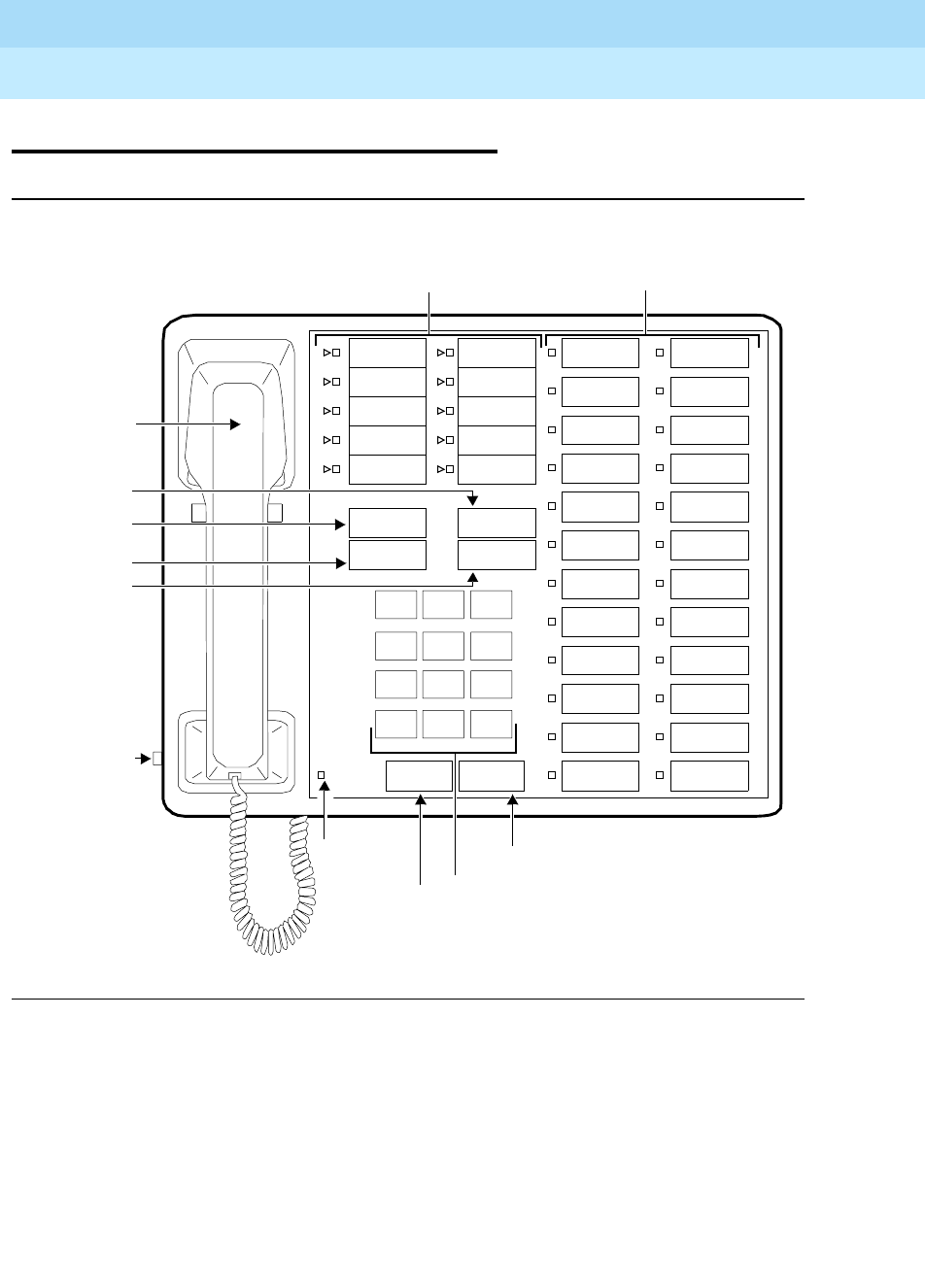
DEFINITYEnterpriseCommunicationsServerandSystem75andSystem85
Terminals and Adjuncts Reference
555-015-201 Issue 11
December 1999
The 7400 Series Voice Terminals
11-37The 7405D Voice Terminal
11
The 7405D Voice Terminal
Figure 11-9. The 7405D Voice Terminal
The 7405D voice terminal is a multi-appearance digital voice terminal which
allows features to be added as the user needs them. The Digital Display can be
added to provide access to the Message Center. A Digital Terminal Data Module
or 7400B can be added to enable the user of a 7405D voice terminal to transmit or
receivedatawithanassociateddataterminal.
Handset
123
456
789
ABC DEF
MNOJKLGHI
PRS TUV WXY
*
O#
Oper
Conference
Drop
Transfer
Hold
10 Call Appearance/
Message
Disconnect
Dial Pad
Message
Hold Button
Transfer
Conference
Drop Button
Volume
Control
(on left
Light Disconnect Button
Button
Feature Buttons
side)
Button
Recall
Recall
Button
24 Feature Buttons
DEFINITYEnterpriseCommunicationsServerandSystem75andSystem85
Terminals and Adjuncts Reference
555-015-201 Issue 11
December 1999
The 7400 Series Voice Terminals
11-38The 7405D Voice Terminal
11
The basic voice terminal provides 10 call appearance/feature buttons with lights
that can be assigned to call appearances or system features. It has
24 programmable feature buttons and six fixed feature buttons. The 7405D can
also have a function key module which adds 24 feature buttons and a call
coverage module (when no display module is used) which adds 20 call
appearance/feature buttons.
NOTE:
The 7405D voice terminal was discontinued in February, 1990.
Applications
The 7405D voice terminal can be used with the DEFINITY Communications
System Generic 1, Generic 2, and Generic 3, the DEFINITY ECS, System 75, and
System 85. Typical applications of the 7405D voice terminal are secretaries,
executives, managers and answering positions that require a large selection of
lines, features, or data transmissions.
Physical Description
Dimensions
NOTE:
The following dimensions for the 7405D voice terminal are approximate.
Width = 10-1/4 inches
Depth (front to back) = 8-3/4 inches
Height (maximum with handset in place) = 6-1/4 inches
Thickness of housing = 1-1/2 inches
Features
Six Fixed Feature Buttons
■CONFERENCE button
■DROP button
■TRANSFER button
■HOLD button
■DISCONNECT button
■RECALL button

DEFINITYEnterpriseCommunicationsServerandSystem75andSystem85
Terminals and Adjuncts Reference
555-015-201 Issue 11
December 1999
The 7400 Series Voice Terminals
11-39The 7405D Voice Terminal
11
Message Light
The green Message light goes on when a message is left for the user. It goes off
when the user retrieves the message.
Call Appearance/Feature Buttons
The 7405D voice terminal has 10 call appearance/feature buttons. Adjacent to
each button is a pair of red and green indicator lights.
Feature-only Buttons
The 7405D voice terminal has 24 feature-only buttons. Adjacent to each button is
a green status light.
Self-Test
The 7405D voice terminal is equipped with a self-test for its buttons and tone
ringer. The self-test switch is located on the left side of the base.
Other Physical Features
Handset
The 7405D voice terminal is equipped with a R-type handset.
Dial pad
The 7405D voice terminal is equipped with a 12-button touch-tone dial pad.
Jacks
The 7405D voice terminal housing contains three jacks. The handset cord jack is
just under the left side of the housing. The handset contains a jack for the handset
cord. The LINE and OTHER jacks are on the rear housing.
Cords
Three cords are supplied with the 7405D voice terminal: a coiled 7-foot modular
handset cord and 7-foot modular line cord. Optional longer cords are available: a
12-foot handset cord; 14-foot and 25-foot line cords.
Ringing
The 7405D voice terminal has electronic tone ringing. The volume control is on
the left side of the housing.
Mounting Options
The 7405D voice terminal comes equipped with an adjustable desk stand.
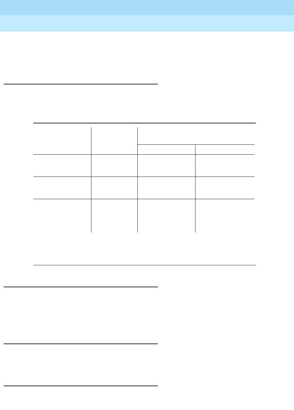
DEFINITYEnterpriseCommunicationsServerandSystem75andSystem85
Terminals and Adjuncts Reference
555-015-201 Issue 11
December 1999
The 7400 Series Voice Terminals
11-40The 7405D Voice Terminal
11
Color Options
The 7405D voice terminal was available in black and misty cream. Since it has
become discontinued, it is only available in black.
Distance Limitations
The maximum allowable distance the 7405D voice terminal can be located from
the switch cabinet is shown in the following table.
Note:
These ranges can be extended to 5,000 feet (1524 m) for 24 AWG wire and 4,000 feet
(1219 m) for 26 AWG wire with the use of a Data Link Protector. Refer to EXPOSED PORT
PROTECTION.
Power Requirements
The 7405D voice terminal receives power from the system and does not require
any external power supply. Additional power is required when the 7405D voice
terminal is equipped with any adjuncts. Refer to the Adjunct Power section
earlier in this manual.
Power Failure Operation
The 7405D voice terminal cannot be used as an emergency station during power
failure transfer conditions.
FCC Registration
The 7405D voice terminal is not FCC registered.
Table 11-7. Distance Limitations for the 7405D Voice Terminal
System Port Board
Nominal Maximum Range in Feet
(Meters) (See Note)
24 AWG 26 AWG
System 85 SN270B
TN754
3,400 (1,034)
3,400 (1,034)
2,200 (671)
2,200 (671)
DEFINITY G2 SN270B
TN754
3,400 (1,034)
3,400 (1,034)
2,200 (671)
2,200 (671)
DEFINITY G1 and
G3, DEFINITY
ECS, and System
75
TN754 3,400 (1,034) 2,200 (671)

DEFINITYEnterpriseCommunicationsServerandSystem75andSystem85
Terminals and Adjuncts Reference
555-015-201 Issue 11
December 1999
The 7400 Series Voice Terminals
11-41The 7405D Voice Terminal
11
Hearing Aid Compatible
This voice terminal is compatible with the inductively coupled hearing aids
prescribed by the FCC.
7405D Equipment PECs
The 7405D voice terminal and optional components were ordered with the
following PECs:
■Basic 7405D Voice Terminal — 3175-40D/CLR
■Handset cord (12 feet) — 2725-01L COL09
■Line cord (14 feet, silver) — 2725-07N COL18
■Line cord (25 feet, silver) — 2725-07S COL18
Adjuncts
The following adjuncts can be used with this voice terminal:
■S101A Speakerphone or 500A Headset Adapter and a standard headset
■S201A Speakerphone
■C401A or C401B Call Coverage Module or D401A or D401B Digital Display
Module (but not both simultaneously)
■F401A Function Key Module
■Z701A Digital Terminal Data Module
■7400B Data Module
Additional Documents
The following documents contain additional information relating to the 7405D
voice terminal:
■
System 85 7405D Voice Terminal User’s Guide
, 555-103-709
■
System 75 7405D Voice Terminal User’s Guide
, 555-200-704
■
DEFINITY Generic 1 and Generic 2, System 75, and System 85 Terminals
and Adjuncts Installation and Test
, 555-015-104
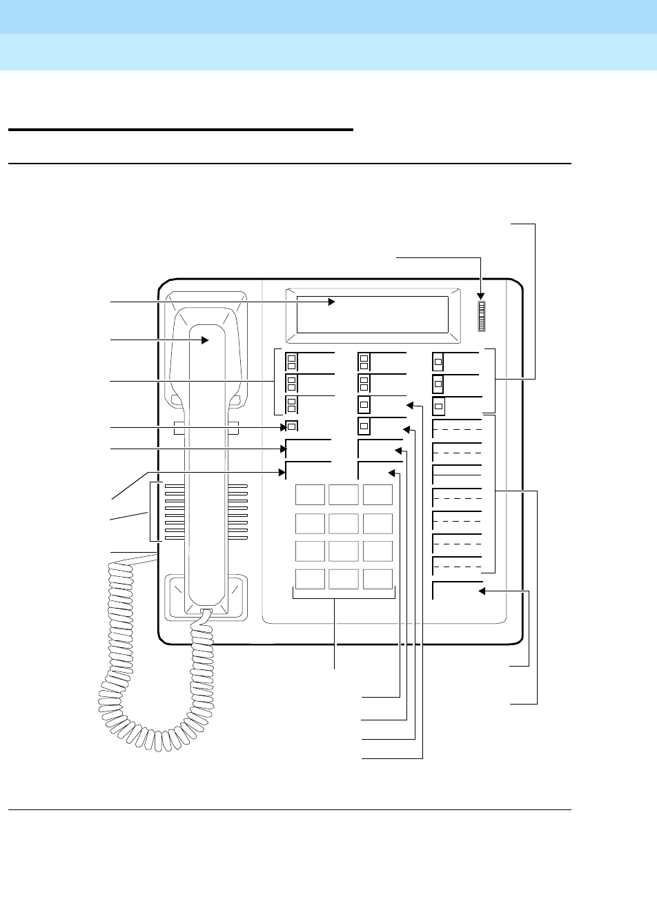
DEFINITYEnterpriseCommunicationsServerandSystem75andSystem85
Terminals and Adjuncts Reference
555-015-201 Issue 11
December 1999
The 7400 Series Voice Terminals
11-42The 7406D, 7406BIS, and 7406 Plus Voice Terminals
11
The 7406D, 7406BIS, and 7406 Plus
Voice Terminals
Figure 11-10. The 7406D (7406D01A or 7406D03A) Voice Terminal with Display
Speaker
Handset
123
456
789
ABC DEF
MNOJKLGHI
PRS TUV WXY
*
O#
Oper
Conference
Drop
Transfer
Hold
5Call
Appearance/
Shift Button
Message
Dial Pad
Feature
Buttons
3 Feature Buttons
Display
Transfer Button
Hold Button
Conference
Speaker
Select Ring
Message
Button
Drop Button
7Two-Level
Feature
Buttons
7406D
Display Viewing
Adjustment
Shift
Ringer
Volume
Control
(on left side
Select Ring Feature Button
Speaker
Light
terminal)
of voice
Button
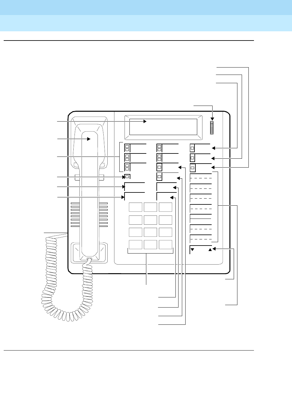
DEFINITYEnterpriseCommunicationsServerandSystem75andSystem85
Terminals and Adjuncts Reference
555-015-201 Issue 11
December 1999
The 7400 Series Voice Terminals
11-43The 7406D, 7406BIS, and 7406 Plus Voice Terminals
11
Figure 11-11. The 7406BIS (7406D05A) Voice Terminal with Display
Volume
Handset
123
456
789
ABC DEF
MNOJKLGHI
PQRS TUV WXYZ
*
O#
Oper
Conference
Drop
Transfer
Hold
5Call
Appearance/
Mute Button
Message Light
Dial Pad
Feature Buttons
Feature Button
Display
Conference Button
Speaker
Select Ring
Speaker
Mute
Message
Drop Button
7 Two-Level
Feature
Buttons
7406 BIS
Shift
Ringer
Volume
Control
(under voice
terminal)
Speaker Button
Display Viewing Adjustment
Shift Button
Transfer Button
Hold Button
Select Ring Feature Button
Button
Control
Volume
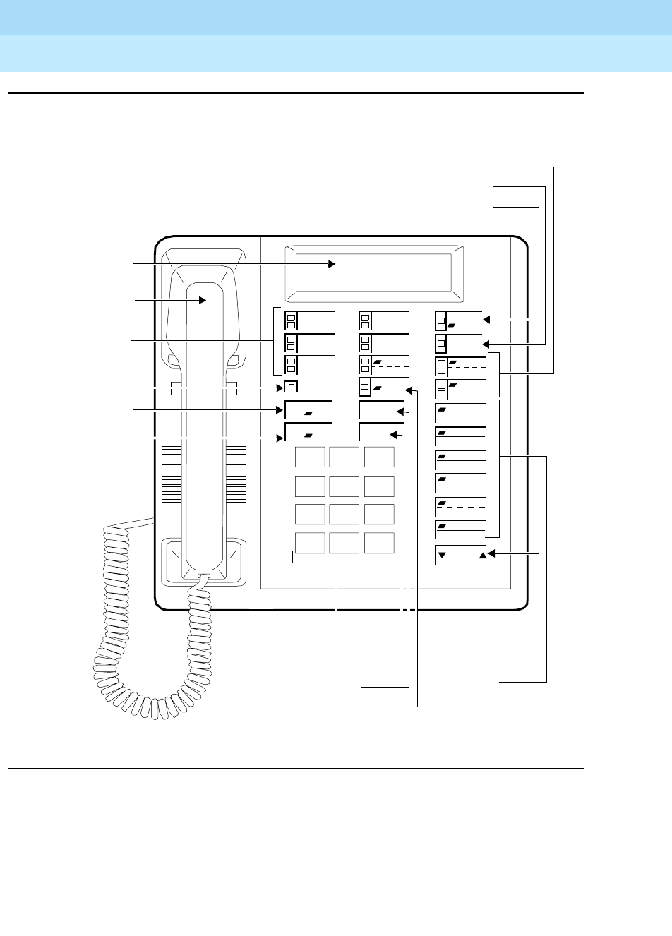
DEFINITYEnterpriseCommunicationsServerandSystem75andSystem85
Terminals and Adjuncts Reference
555-015-201 Issue 11
December 1999
The 7400 Series Voice Terminals
11-44The 7406D, 7406BIS, and 7406 Plus Voice Terminals
11
Figure 11-12. The 7406 Plus (7406D07A) Voice Terminal with Display
Volume
Handset
123
456
789
ABC DEF
MNOJKLGHI
PQRS TUV WXYZ
*
O#
Oper
Conference
Drop
Transfer
Hold
5Call
Appearance/
Mute Button
Message Light
Dial Pad
Feature Buttons
Display
Conference/
Volume
Ring
Test
Select
Speaker
Mute
Reset Spkr
Message
Ring Button
Drop/Test
Button
3 Two-Level Feature Buttons (with lights)
6Two-Level
Feature
Buttons
7406 Plus
Select Button
Transfer Button
Hold Button
Button
Control
Speaker/Reset Spkr Button
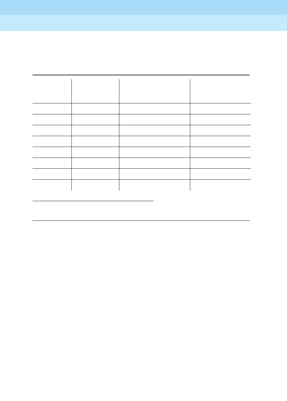
DEFINITYEnterpriseCommunicationsServerandSystem75andSystem85
Terminals and Adjuncts Reference
555-015-201 Issue 11
December 1999
The 7400 Series Voice Terminals
11-45The 7406D, 7406BIS, and 7406 Plus Voice Terminals
11
The 7406D (four versions), 7406BIS (two versions), and 7406 Plus (two versions)
multi-appearance digital voice terminals are described in the following table and in
the following information.
The 7406D (which includes the 7406D01A, 7406D02A, 7406D03A, and
7406D04A versions)— has five call appearance/feature buttons, each with a red
in-use light and a green status light, seven shiftable (2-level) programmable
feature buttons with no lights, four programmable feature buttons with a green
light, four fixed feature buttons (CONFERENCE, TRANSFER, DROP, and HOLD),
a SHIFT button with a green light, a SPEAKER button, and a green Message light.
The 7406BIS (which includes the 7406D05A and 7406D06A versions)— has five
call appearance/feature buttons, each with a red in-use light and a green status
light, seven shiftable (2-level) programmable buttons with no lights, two
programmable feature buttons with a green light, four fixed feature buttons
(CONFERENCE, TRANSFER, DROP, and HOLD), a SHIFT button with a green
light, a SPEAKER button with a green light, a MUTE button with a red light, a
SPEAKER VOLUME “arrow” button, and a red Message light.
Table 11-8. The Types of 7406 Voice Terminals
Ver sion
2 x 24
Character
Display
Data Capability with
the Following
Built-In
Speakerphone
7406D01A Yes Z703AL1 / 7400B No
7406D02A No*
* Display features can be used on a data terminal if equipped with Z703AL1 DSU.
Z703AL1 / 7400B No
7406D03A Yes 7400B No
7406D04A No 7400B No
7406D05A Yes 7400B Yes
7406D06A No 7400B Yes
7406D07A Yes 7400B Yes
7406D08A No 7400B Yes
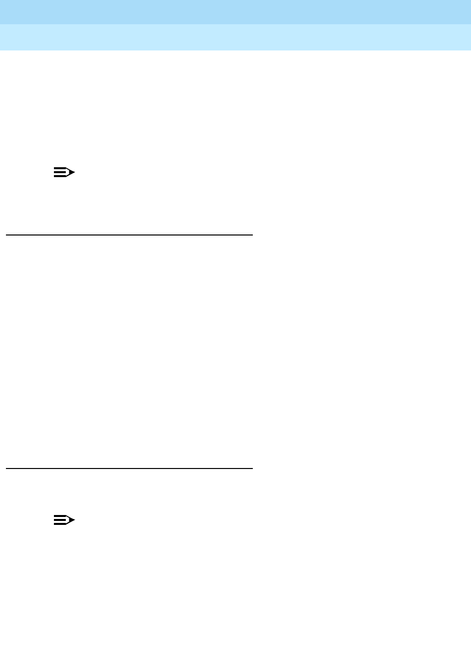
DEFINITYEnterpriseCommunicationsServerandSystem75andSystem85
Terminals and Adjuncts Reference
555-015-201 Issue 11
December 1999
The 7400 Series Voice Terminals
11-46The 7406D, 7406BIS, and 7406 Plus Voice Terminals
11
The 7406 Plus (which includes the 7406D07A and 7406D08A versions)— are the
newest 7406 sets. The 7406 Plus voice terminal has five call appearance/feature
buttons, each with a red in-use light and a green status light, three shiftable
(2-level) programmable feature buttons with a green light, six shiftable (2-level)
programmable feature buttons without lights, four fixed feature buttons
(CONFERENCE, TRANSFER, DROP, and HOLD), a SELECT button with a green
light, a SPEAKER/RESET SPKR button with a green light, a MUTE button with a
red light, a VOLUME “arrow” button, and a red Message light.
NOTE:
The 7406D01A through 7406D06A are no longer being manufactured. The
7406D07A and 7406D08A were discontinued in1995.
Applications
The 7406D, 7406BIS, and 7406 Plus voice terminals can be used with the
DEFINITY Communications System Generic 1, Generic 2, and Generic 3, the
DEFINITY ECS, System 75, and System 85. These 7406 digital voice terminals
are the least expensive digital voice terminals with a display that Lucent
Technologies offers. Typical applications of the 7406D, the 7406BIS, and the 7406
Plus voice terminal are users who have a need for calling party display capabilities
or with data terminals requiring a large number of features.
The 7406D, 7406BIS, and 7406 Plus voice terminals can also provide the user
with simultaneous voice and data communications: The 7406D (7406D01A –
7406D04A) are equipped with a data stand; the 7406BIS (7406D05A and
7406D06A) and the 7406 Plus (7406D07A and 7406D08A) can be connected to a
7400B Data Module. With the 7406BIS and 7406 Plus voice terminals, PC
platform products can be useful in providing voice capabilities since these
screen-based products can greatly enhance the telephone capabilities of these
voice terminals.
Physical Description
Dimensions
NOTE:
The following dimensions listed here for the 7406D, 7406BIS, and 7406 Plus
voice terminals are approximate.
Width = 8-1/2 inches
Depth (front to back) = 8-3/4 inches
Height (maximum with handset in place) = 6-1/4 inches
Thickness of housing = 1-1/2 inches

DEFINITYEnterpriseCommunicationsServerandSystem75andSystem85
Terminals and Adjuncts Reference
555-015-201 Issue 11
December 1999
The 7400 Series Voice Terminals
11-47The 7406D, 7406BIS, and 7406 Plus Voice Terminals
11
Feature Buttons
The 7406D, 7406 BIS, and 7406 Plus voice terminals have the following buttons
and features:
Four Standard Fixed Feature Buttons
The 7406D, 7406BIS, and 7406 Plus have the following four standard fixed feature
buttons:
■CONFERENCE or CONFERENCE/RING button
■DROP or DROP/TEST button
■TRANSFER button
■HOLD button
Message light
The 7406D, 7406BIS, and the 7406 Plus have a Message light. The Message light
goes on when a message is left for the user. It goes off when the user has
retrieved the message.
SHIFT button (on 7406D and 7406BIS)
The 7406D and 7406BIS (7406D01A—7406D06A) voice terminals have a SHIFT
button which allows programming and use of a second feature or phone number
for the seven double-level buttons. When the user presses the SHIFT button (and
the light next to the button is on), the top-level feature on the shiftable (2-level)
button can be used. (When the SHIFT button light is off, the feature assigned to
the lower half of the shiftable button can be used.)
SELECT RING button (on 7406D and 7406BIS)
The 7406D and 7406BIS (7406D01A—7406D06A) voice terminals have a
SELECT RING button which is used for selecting a personalized ringing pattern.
(There are eight different patterns to choose from.)
SELECT button (on 7406 Plus only)
The 7406 Plus (7406D07A and 7406D08A) voice terminals have a SELECT
button which can be used in four different ways:
■Used with a 2-level feature button to access the top-labeled feature
■Used with the DROP/TEST button to initiate a self-test of your voice
terminal
■Used with the CONFERENCE/RING button to select your own
personalized ring from among eight available patterns
■Used with the SPEAKER/RESET SPKR button to perform an acoustic test
of the environment and adjust the speakerphone to the surrounding
acoustic environment for optimal performance

DEFINITYEnterpriseCommunicationsServerandSystem75andSystem85
Terminals and Adjuncts Reference
555-015-201 Issue 11
December 1999
The 7400 Series Voice Terminals
11-48The 7406D, 7406BIS, and 7406 Plus Voice Terminals
11
Call Appearance/Feature Buttons
The 7406D, 7406BIS, and 7406 Plus voice terminals have five call
appearance/feature buttons.
One-level Feature-only and Two-level Feature-only Buttons
The 7406D (7406D01A—7406D04A) voice terminals have three buttons that can
be used for one feature each, with a green light, and seven double-level feature
buttons without lights. There is also a Select Ring/Feature button with the Select
Ring option on the top level; another feature can be administered on the bottom
level.
The 7406BIS (7406D05A and 7406D06A) voice terminals have one single-level
feature button with a green light and seven double-level feature buttons without
lights. There is also a Select Ring/Feature button with the Select Ring option on
the top level; another feature can be administered on the bottom level.
The 7406 Plus (7406D07A and 7406D08A) voice terminals have three
double-level feature buttons, each with a green light. These voice terminals also
have six double-level feature buttons without lights.
Speakerphone (on 7406BIS and 7406 Plus)
The 7406BIS and 7406 Plus (7406D05A—7406D08A) voice terminals are
equipped with a built-in speakerphone. The Speakerphone capability allows a
user to engage in a hands-free conversation with the far-end party. The
speakerphone can be turned off or on (on the 7406BIS voice terminal, use the
SPEAKER button; on the 7406 Plus voice terminal, use the SPEAKER/RESET
SPKR button), can be muted (use the MUTE button), and the volume can be
raised and lowered (use the Volume “arrow” button).
The Speakerphone feature on the 7406 Plus also allows the user to adjust the
speakerphone for optimal performance. By pressing the SELECT button and then
the SPEAKER/RESET SPKR button (if the voice terminal is set for the
Speakerphone feature), the user hears a set of tones as the speakerphone
performs an acoustic test of the environment. When the tones stop, the
speakerphone has finished adjusting itself and is ready for use. The user
must
reset the speakerphone in any one of three instances: whenever the voice
terminal is moved to another place (even in the same room), whenever the green
light next to the SPEAKER/RESET SPKR button is fluttering, and, when, in the
unlikely event, the speakerphone is making a squealing sound.
On the 7406D voice terminals, the volume control for the speaker is a sliding
control also used for the tone ringer volume. On the 7406BIS voice terminal, the
volume control button is labeled SPEAKER VOLUME and double arrows, one for
raising the volume level and one for lowering the volume; on the 7406 Plus voice
terminal, the volume control button is labeled with the word VOLUME and the
double arrows for raising and lowering the volume.

DEFINITYEnterpriseCommunicationsServerandSystem75andSystem85
Terminals and Adjuncts Reference
555-015-201 Issue 11
December 1999
The 7400 Series Voice Terminals
11-49The 7406D, 7406BIS, and 7406 Plus Voice Terminals
11
Loudspeaker/Spokesman/Speaker Feature
The 7406D (7406D01A—7406D04A) voice terminals are equipped with a built-in,
listen-only loudspeaker/Spokesman®capability. Use the SPEAKER button for
turning on and off the loudspeaker.
The 7406BIS and the 7406 Plus (7406D05A—7406D08A) voice terminals come
with a built-in speakerphone that can be optioned for Spokesman operation.
(Since changing the internal jumper setting requires removing the back of the
voice terminal, converting the voice terminal Speakerphone feature to the
Speaker feature should be done
only
by qualified service personnel.) These voice
terminals are shipped with the Speakerphone setting in place.
The Spokesman capability allows a user to engage in a one-way conversation
with the far-end. Specifically, the user can only listen to the far-end; the user is not
able to transmit his voice over the Spokesman. To speak with the far-end, the user
must use the handset.
With the 7406D and 7406BIS voice terminals, the handset and Spokesman
capability can be used simultaneously. With the 7406 Plus voice terminal, the
handset and speaker
cannot
be used at the same time.
MUTE button (on 7406BIS and 7406 Plus)
The 7406BIS and the 7406 Plus (7406D05A—7406D08A) voice terminals are
equipped with a MUTE button. This button is a fixed feature button with a red
status light. The MUTE button turns off the microphone of the built-in
speakerphone or the handset so that a person can converse with another person
in the room without the other party listening in.
VOLUME button (on 7406BIS and 7406 Plus)
The 7406BIS (7406D05A and 7406D06A) voice terminal has a SPEAKER
VOLUME “arrow” button on the bottom right side of the faceplate which controls
the volume of the built-in speakerphone. The left side of the VOLUME button
lowers the volume; the right side of the button raises the volume.
The 7406 Plus (7406D07A and 7406D08A) voice terminal also has a VOLUME
“arrow” button on the bottom right side of the faceplate. However, this button has a
double function. When the user is using the speakerphone, the VOLUME button
controls the volume of the speakerphone; at all other times, the button controls the
volume of the tone ringer.
If the 7406BIS or 7406 Plus voice terminal has a display (the 740605A and
7406D07A voice terminals only), the display will show a “bar array” that indicates
thevolumesetting.

DEFINITYEnterpriseCommunicationsServerandSystem75andSystem85
Terminals and Adjuncts Reference
555-015-201 Issue 11
December 1999
The 7400 Series Voice Terminals
11-50The 7406D, 7406BIS, and 7406 Plus Voice Terminals
11
Self-Test
Two of the 7406D voice terminals (the 7406D03A and 7406D04A) and the
7406BIS voice terminals (7406D05A and 7406D06A) are equipped with a
self-test. On these voice terminals, the Self-Test feature is performed by pressing
the SHIFT button and then the DROP button.
With the 7406 Plus (7406D07A and 7406D08A) voice terminals, the user presses
the SELECT button and then the DROP/TEST button to initiate a self-test for the
voice terminal.
During the self-test, all the lights go on, the ringer sounds, and, if the voice
terminal has a display, the display characters are lit. The self-test ends when the
user releases the DROP or DROP/TEST button.
Other Physical Features
Handset
The 7406D, 7406BIS, and 7406 Plus voice terminals are equipped with an R-type
handset.
Dial pad
The 7406D, 7406BIS, and 7406 Plus voice terminals are equipped with a
12-button touch-tone dial pad. On the 7406 Plus voice terminal, the letters “Q” and
“Z” have been added to the appropriate dial pad keys for directory access, and the
“5” button on your dial pad has raised bars for visually-impaired users.
Jacks
The 7406D, 7406BIS, and 7406 Plus voice terminals’ housing contains three
jacks. The Handset cord jack is just under the left side of the housing. The Line
jack and the Speakerphone/headset adapter jack are on the back of the voice
terminal.
Cords
Two cords are supplied with the 7406D, 7406BIS and 7406 Plus voice terminals: a
coiled 9-foot handset cord and a 7-foot line cord.
Optional longer cords are available: a 12-foot handset cord; 14-foot and 25-foot
line cords.
Ringing
The 7406D, 7406BIS, and the 7406 Plus voice terminals have electronic tone
ringing. With the Personalized Ringing feature, the user can select any one of
eight different ringing patterns.
On the 7406D and 7406BIS (7406D01A—7406D06A) voice terminals, the volume
control is on the left side of the housing.
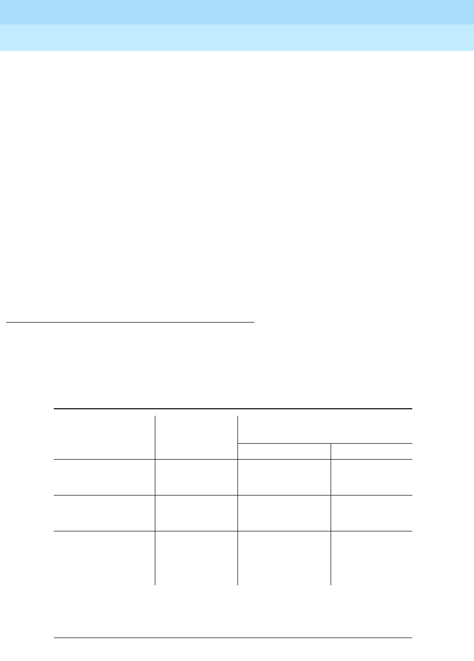
DEFINITYEnterpriseCommunicationsServerandSystem75andSystem85
Terminals and Adjuncts Reference
555-015-201 Issue 11
December 1999
The 7400 Series Voice Terminals
11-51The 7406D, 7406BIS, and 7406 Plus Voice Terminals
11
On the 7406 Plus (7406D07A and 7406D08A), tone ringer volume is controlled by
the VOLUME “arrow” button. When the speakerphone is active, the VOLUME
button controls the volume of the speakerphone; at all other times, the button
controls the volume of the tone ringer.
Mounting Options
Two of the 7406D voice terminals (7406D01A and 7406D02A) come equipped
with a nonadjustable desk stand, an optional data stand, or can be wall-mounted
(without data capabilities).
Two of the 7406D voice terminals (7406D03A, 7406D04A), the 7406BIS
(7406D05A, 7406D06A), and the 7406 Plus (7406D07A, and 7406D08A) voice
terminals come with a nonadjustable desk stand only. An optional wall mount kit is
available.
Color Options
The 7406D, 7406BIS, and 7406 Plus voice terminals are available in black and
misty cream.
Distance Limitations
The maximum allowable distances of a 7406D or a 7406 Plus voice terminal from
the DEFINITY G1, G2, G3, the DEFINITY ECS, System 75, or System 85 cabinet
are shown in the following table.
Note:
These ranges can be extended to 5,000 feet (1524 m) for 24 AWG wire and 4,000 feet
(1219 m) for 26 AWG wire with the use of a Data Link Protector. Refer to the Exposed Port
Protection section earlier in this manual.
Table 11-9. Distance Limitations for the 7406D, 7406BIS, and 7406 Plus
Voice Terminals
System Port Board
Nominal Maximum Range in Feet
(Meters) (See Note)
24 AWG 26 AWG
System 85 SN270B
TN754
3,400 (1,034)
3,400 (1,034)
2,200 (671)
2,200 (671)
DEFINITY G2 SN270B
TN754
3,400 (1,034)
3,400 (1,034)
2,200 (671)
2,200 (671)
DEFINITY G1
and G3,
DEFINITY ECS,
and System 75
TN754 3,400 (1,034) 2,200 (671)

DEFINITYEnterpriseCommunicationsServerandSystem75andSystem85
Terminals and Adjuncts Reference
555-015-201 Issue 11
December 1999
The 7400 Series Voice Terminals
11-52The 7406D, 7406BIS, and 7406 Plus Voice Terminals
11
Power Requirements
The 7406D, 7406BIS, and 7406 Plus voice terminals receive power from the
system and do not require any external power supply. Additional power is required
when these voice terminals are equipped with any adjuncts or the Z703AL1 data
stand. Refer to the Adjunct Power section earlier in this manual.
Switch Administration
Aliasing
The 7406 voice terminals must be aliased in the following way:
CAVEATS:
For System 75, R1V1 and System 85, R1V2, V3, and V4, the following caveats
apply:
— 7406D02A, 7406D04A, 7406D06A, 7406D08A aliased as 7405D;
— 7406D02A, 7406D04A, 7406D06A, 7406D08A w/7400B Data Module
aliased as 7405 w/ Data Module;
— 7406D01A, 7406D03A, 7406D05A, 7406D07A aliased as 7405D w/Digital
Display Module;
— 7406D01A, 7406D03A, 7406D05A, 7406D07A w/7400B Data Module
aliased as 7405D w/Data Module and Digital Display Module;
Table 11-10. Administering the 7406D, 7406BIS, and 7406 Plus Voice Terminals
If you are administering
this system:
For this type of
voice terminal:
The voice terminal must
be administered as:
System 75, R1V1
System 85, R2V1, V2, V3 7406D
7406BIS
7406 Plus
a 7405D voice terminal
(See CAVEATS below)
System 75, R1V2 or above
DEFINITY G1 and G3, and
DEFINITY ECS
System 85, R2V4 or above
DEFINITY G2
7406D
7406BIS
itself
System 75, R1V2 or above
DEFINITY G1 and G3, the
DEFINITY ECS
System 85, R2V4 or above
DEFINITY G2
7406 Plus a 7406D voice terminal
or
7406BIS voice terminal

DEFINITYEnterpriseCommunicationsServerandSystem75andSystem85
Terminals and Adjuncts Reference
555-015-201 Issue 11
December 1999
The 7400 Series Voice Terminals
11-53The 7406D, 7406BIS, and 7406 Plus Voice Terminals
11
— 7406D01A and 7406D02A w/Z703A DSU aliased as 7405D w/Data Module
and Digital Display Module.
Button Numbering
The 7406D and 7406 Plus voice terminal button diagrams on the following pages
will help you administer the 7406D, 7406BIS, and the 7406 Plus voice terminals
on a System 75, a DEFINITY G1 and G3, or a DEFINITY ECS, and on a
System 85 and a DEFINITY G2. In Figures 11-13 through 11-16:
■The numbers on the five administrable call appearance and feature buttons
correspond to button assignments on Page 2 of the voice terminal
administration screen forms.
■The numbers on the administrable feature-only buttons correspond to
feature button assignments on Page 3 of the voice terminal administration
screen form.
Figures 11-13 and 11-14 refer to the button numbering for the 7406D and
7406BIS voice terminals; Figures11-15 and 11-16 refer to the 7406 Plus voice
terminal.
If you need more information, refer to
DEFINITY Communications System
Generic 3 Implementation
, 555-230-653, and
DEFINITY Communications System
Generic 2 Administration of Features and Hardware
, 555-104-507, for your
specific system.
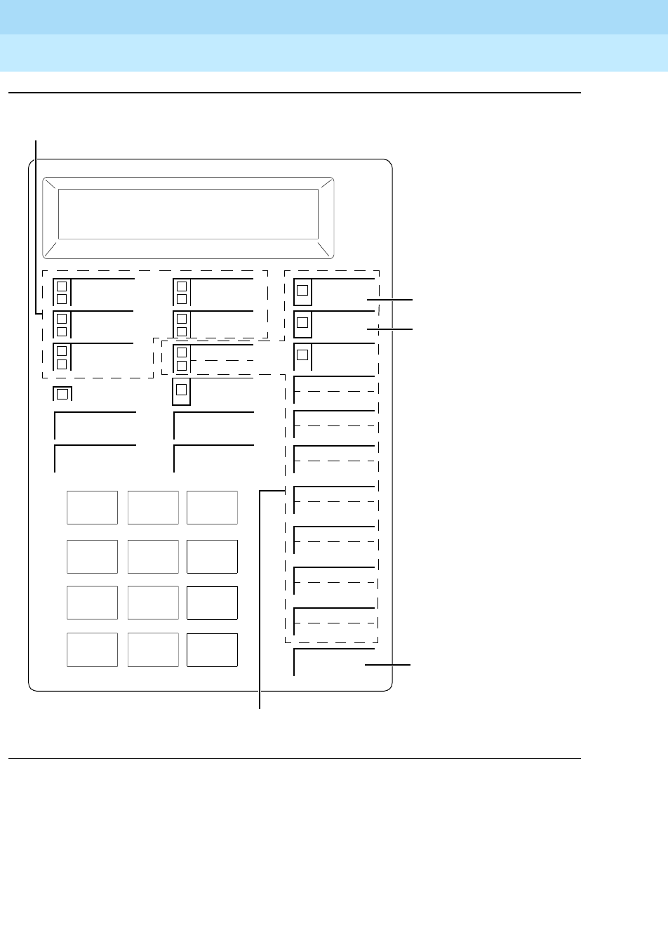
DEFINITYEnterpriseCommunicationsServerandSystem75andSystem85
Terminals and Adjuncts Reference
555-015-201 Issue 11
December 1999
The 7400 Series Voice Terminals
11-54The 7406D, 7406BIS, and 7406 Plus Voice Terminals
11
Figure 11-13. Button Numbering for Administering the 7406D and 7406BIS Voice
Terminals Connected to a System 75, a DEFINITY G1 or G3, or a
DEFINITY ECS
123
456
789
ABC DEF
MNOJKLGHI
PRS TUV WXY
*O#
Oper
Conference
Drop
Transfer
Hold
Message
Select Ring
4
5
1
3
1
2
Shift
2
3
4
12
5
13
6
14
7
15
8
16
9
17
10
18
11
Speaker
Administrable Call Appearance/Feature Buttons
Administrable Feature-Only Buttons
On the 7406BIS
(7406D05A and 7406D06A)
Voice Terminals, Button #2
is the Speaker Button.
Button #3 is the Mute Button.
The Button shown as
“Speaker” is the Speaker
Volume Button on the
7406BIS.
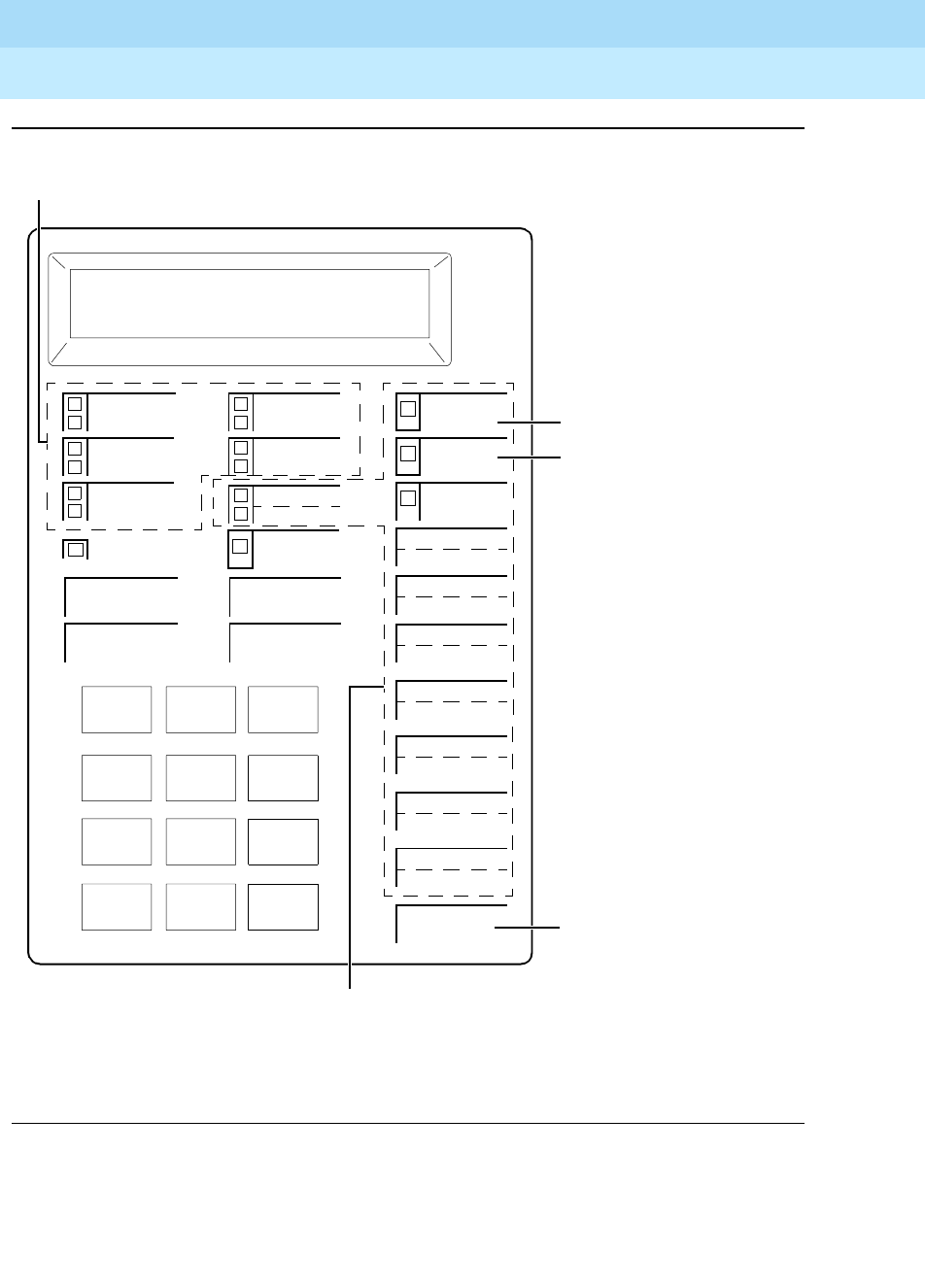
DEFINITYEnterpriseCommunicationsServerandSystem75andSystem85
Terminals and Adjuncts Reference
555-015-201 Issue 11
December 1999
The 7400 Series Voice Terminals
11-55The 7406D, 7406BIS, and 7406 Plus Voice Terminals
11
Figure 11-14. Button Numbering for Administering the 7406D and 7406BIS Voice
Terminals Connected to a System 85 or a DEFINITY G2
123
456
789
ABC DEF
MNOJKLGHI
PRS TUV WXY
*O#
Oper
Conference
Drop
Transfer
Hold
Message
Select Ring
6
7
13
5
3
4
Shift
14
15
16
24
17
25
18
26
19
27
20
28
21
29
22
30
23
Speaker
Administrable Call Appearance/Feature Buttons
Administrable Feature-Only Buttons
NOTE: The Hold Button is button #1.
On the 7406BIS
(7406D05A and 7406D06A)
Voice Terminals, Button #14
is the Speaker Button.
Button #15 is the Mute Button.
The Button shown as
“Speaker” is the Speaker
Volume Button on the 7406BIS.
The Message Light is Button #2.
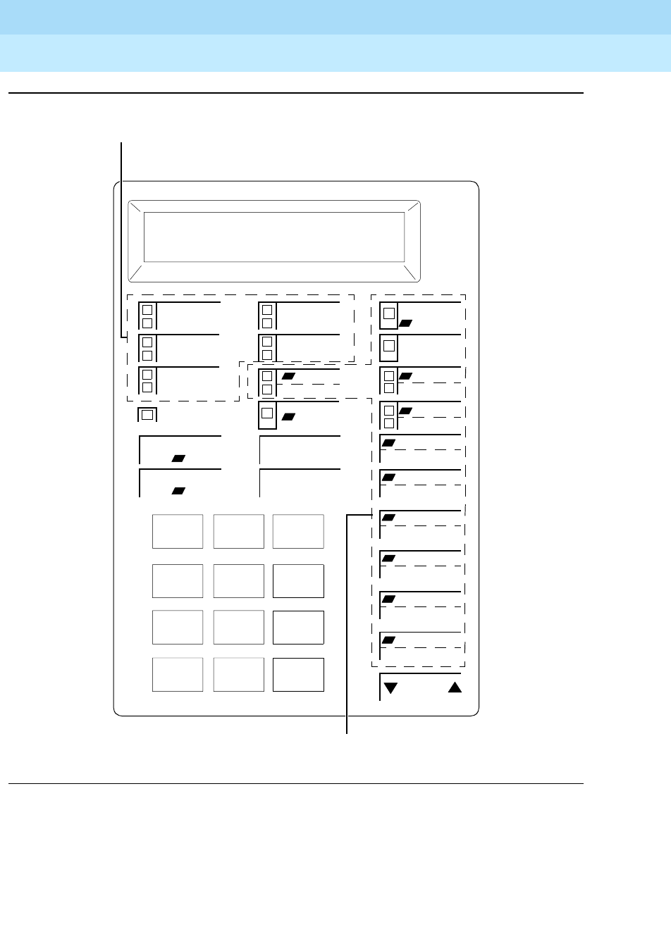
DEFINITYEnterpriseCommunicationsServerandSystem75andSystem85
Terminals and Adjuncts Reference
555-015-201 Issue 11
December 1999
The 7400 Series Voice Terminals
11-56The 7406D, 7406BIS, and 7406 Plus Voice Terminals
11
Figure 11-15. Button Numbering for Administering the 7406 Plus Voice Terminal
Connected to a System 75, a DEFINITY G1 or G3, or a DEFINITY ECS
123
456
789
ABC DEF
MNOJKLGHI
PQRS TUV WXYZ
*O#
Oper
Conference
Drop
Transfer
Hold
Message
2
4
5
1
3
1
2
Select
Speaker
Mute
4
13
6
14
7
15
8
16
9
17
10
18
11
Administrable Call Appearance/Feature Buttons
Administrable Feature-Only Buttons
Ring
Test
Reset Spkr
3
12
5
Volume
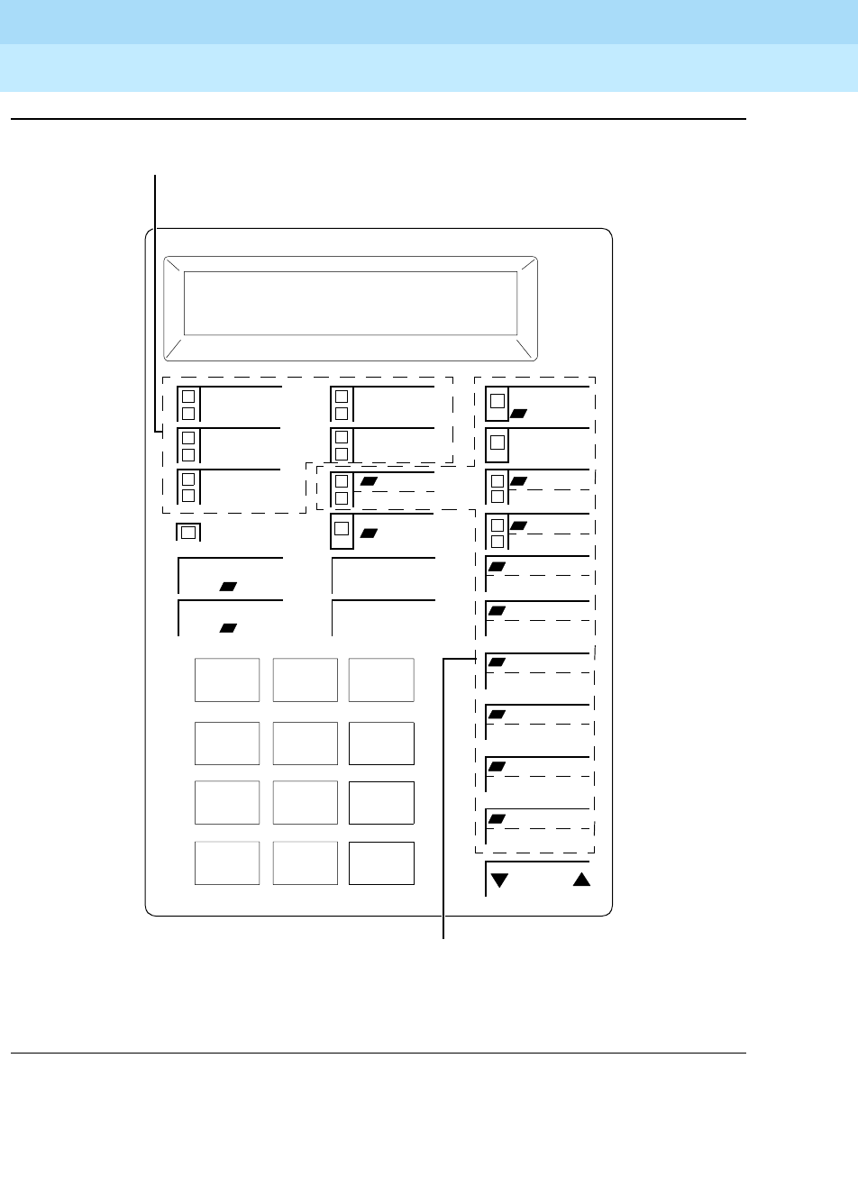
DEFINITYEnterpriseCommunicationsServerandSystem75andSystem85
Terminals and Adjuncts Reference
555-015-201 Issue 11
December 1999
The 7400 Series Voice Terminals
11-57The 7406D, 7406BIS, and 7406 Plus Voice Terminals
11
Figure 11-16. Button Numbering for Administering the 7406 Plus Voice Terminal
Connected to a System 85 or a DEFINITY G2
123
456
789
ABC DEF
MNOJKLGHI
PQRS TUV WXYZ
*O#
Oper
Conference
Drop
Transfer
Hold
Message
14
6
7
13
5
3
4
Select
Speaker
Mute
16
25
18
26
19
27
20
28
21
29
22
30
23
Administrable Call Appearance/Feature Buttons
Administrable Feature-Only Buttons
Ring
Test
Reset Spkr
15
24
17
Volume
NOTE: The Hold Button is Button #1.
The Message Light is Button #2.

DEFINITYEnterpriseCommunicationsServerandSystem75andSystem85
Terminals and Adjuncts Reference
555-015-201 Issue 11
December 1999
The 7400 Series Voice Terminals
11-58The 7406D, 7406BIS, and 7406 Plus Voice Terminals
11
Power Failure Operation
The 7406D, 7406BIS, and 7406 Plus voice terminals cannot be used as an
emergency station during power failure transfer conditions.
FCC Registration
These voice terminals are FCC-registered along with the switch (as a system), but
do not have a separate FCC registration label.
UL and CSA Approval
These voice terminals have been tested and have met the Underwriters
Laboratories (UL) Standards UL 1459 and have also met the Canadian Standards
Association (CSA) Standards CSA-C22.2 No.225-M90.
Hearing Aid Compatibility
The 7406D, 7406BIS, and 7406 Plus voice terminals are compatible with the
inductively coupled hearing aids prescribed by the FCC.
7406D/7406BIS Equipment PECs and Comcodes
The 7406D01A—7406D06A voice terminals and components can be ordered with
the following PECs and Comcodes:
■Basic 7406D01A Voice Terminal with display (and with data stand)
PEC: 3182-LCD (Black=COL09; Misty Cream=COL22)
Comcode: Black= 103976536; Misty Cream=103976601
■Basic 7406D02A Voice Terminal without display (with data stand)
PEC: 3183-BDT (Black=COL09; Misty Cream=COL22)
Comcode: Black=105206585; Misty Cream=105206593
■Basic 7406D03A Voice Terminal with display (without data stand)
PEC: 3182-LDM (Black=COL09; Misty Cream=COL22)
Comcode: Black=105675417; Misty Cream=105675425
■Basic 7406D04A Voice Terminal without display (without data stand)
PEC: 3183-LDM (Black=COL09; Misty Cream=COL22)
Comcode: Black=105675433; Misty Cream=105675441
■Basic 7406D05A Voice Terminal with display with built-in
speakerphone
PEC: 3182-BIS (Black=COL09; Misty Cream=COL22)
Comcode: Black=105703441; Misty Cream=105703458

DEFINITYEnterpriseCommunicationsServerandSystem75andSystem85
Terminals and Adjuncts Reference
555-015-201 Issue 11
December 1999
The 7400 Series Voice Terminals
11-59The 7406D, 7406BIS, and 7406 Plus Voice Terminals
11
■Basic 7406D06A Voice Terminal without display with built-in
speakerphone
PEC: 3183-BIS (Black=COL09; Misty Cream=COL22)
Comcode: Black=105703466; Misty Cream=105703474
■Handset
PEC: 3152-006 (Black=COL09; Misty Cream=COL22)
Comcode: Black=105519086; Misty Cream=105520787
■Handset cord (9 feet)
Comcode: Black=105635429; Misty Cream=105635437
■Handset cord (12 feet)
PEC: 2725-01L (Black=COL09; Misty Cream=COL22)
Comcode: Black=102401445; Misty Cream=104211339
■Line cord (7 feet, silver)
Comcode: 103786778
■Line cord (14 feet, silver)
PEC: 2725-07N COL18
Comcode: 103786802
■Line cord (25 feet, silver)
PEC: 2725-07S COL18
Comcode: 103786828
■Graphic panel (for the 7406D01A, 7406D02A, 7406D03A, and
7406D04A)
Comcode: Black=846344331; Misty Cream=846344349
■Graphic panel (for the 7406D05A and 7406D06A)
Comcode: Black=846365203; Misty Cream=846365211
■Button designation strip
PEC: 31823 (Package of 25) (Black=CLR09; Misty Cream=CLR22)
Comcode: Black=845783687; Misty Cream=845783760
■Display bezel (for display-equipped sets)
Comcode: Black=846100501; Misty Cream=846781970
■Blank bezel (for sets without display)
Comcode: Black=846100519; Misty Cream=845752218
■Wall mount kits
(for mounting the 7406D without display)
Comcode: 31821
(for mounting the 7406D with display)
Comcode: 31820
(for mounting the 7406BIS)
Comcode: 31830

DEFINITYEnterpriseCommunicationsServerandSystem75andSystem85
Terminals and Adjuncts Reference
555-015-201 Issue 11
December 1999
The 7400 Series Voice Terminals
11-60The 7406D, 7406BIS, and 7406 Plus Voice Terminals
11
7406 Plus Equipment PECs and Comcodes
The 7406 Plus voice terminal and components can be ordered with the following
PECs and Comcodes:
■Basic 7406D07A Voice Terminal with display with built-in
speakerphone
PEC: 3182-PLS (Black=COL09; Misty Cream=COL22)
Comcode: Black=106202443; Misty Cream=106202450
■Basic 7406D08A Voice Terminal without display with built-in
speakerphone
PEC: 3183-PLS (Black=COL09; Misty Cream=COL22)
Comcode: Black=106202468; Misty Cream=106202476
■Handset
PEC: 3152-006
Comcode: Black=105519086; Misty Cream=105520787
■Handset cord (9 feet)
Comcode: Black=105635429; Misty Cream=105635437
■Handset cord (12 feet)
PEC: 2725-01L (Black=COL09; Misty Cream=COL22)
Comcode: Black=102401445; Misty Cream=104211339
■Line cord (7 feet, silver)
Comcode: 103786778
■Line cord (14 feet, silver)
PEC: 2725-07N COL18
Comcode: 103786802
■Line cord (25 feet, silver)
PEC: 2725-07S COL18
Comcode: 103786828
■Graphic panel
Comcode: Black=846517134; Misty Cream=846517142
■Button designation cards
PEC: 31827 (Package of 25 cards)
Single card Comcode: 846519056
25 cards Comcode: 846518124
200 cards Comcode: 846518132
500 cards Comcode: 846518140
■Display bezel (for display-equipped sets)
Comcode: Black=846534055; Misty Cream=846534063
■Blank bezel (for sets without display)
Comcode: Black=846534097; Misty Cream=846534105
■Wall mount kit
Comcode: 106304298

DEFINITYEnterpriseCommunicationsServerandSystem75andSystem85
Terminals and Adjuncts Reference
555-015-201 Issue 11
December 1999
The 7400 Series Voice Terminals
11-61The 7406D, 7406BIS, and 7406 Plus Voice Terminals
11
Adjuncts
The following adjuncts can be used with this voice terminal:
■S101A Speakerphone (no longer orderable)
■S201A Speakerphone
■CS201A Speakerphone
■7400B Data Module
■500A Headset Adapter (and a standard headset; see “Headsets” below)
■R6 Amplifier Handset (PEC: 3152-002)
■R8 Noisy Location Handset (PEC: 3152-003)
■R2H Standard Handset (PEC: 3152-006)
■Shoulder Rest
Headsets
A list of compatible headsets, consisting of both modular and plug prong base
units and selection of headpieces, appears in “Headset Adapters” in the Adjuncts
section later in this manual.
Additional Documents
The following documents contain additional information relating to the 7406D,
7406BIS, and 7406 Plus voice terminals: (Use the 9-digit number listed after each
document to order the book from the BCS Publications Center for Lucent
Technologies.)
■
7406 Voice Terminal Installation Instructions
, 555-015-108
■
System 75 7406D Voice Terminal User’s Guide
, 555-200-719
■
DEFINITY Communications System Generic 1 7406D Voice Terminal
User’s Guide
, 555-204-719
■
DEFINITY Communications System Generic 2 and System 85 7406D
Voice Terminal User’s Guide
, 555-104-702
■
System 75 7406BIS Voice Terminal User’s Guide
, 555-200-737
■
DEFINITY Communications System Generic 1 7406BIS User’s Guide
,
555-204-737
■
DEFINITY Communications System Generic 2 and System 85 7406BIS
User’s Guide
, 555-104-721
■
DEFINITY Communications System Generic 1 and System 75 7406 Plus
Voice Terminal User’s Guide
, 555-204-741
■
DEFINITY Communications System Generic 2 and System 85 7406 Plus
Voice Terminal User’s Guide
, 555-104-741

DEFINITYEnterpriseCommunicationsServerandSystem75andSystem85
Terminals and Adjuncts Reference
555-015-201 Issue 11
December 1999
The 7400 Series Voice Terminals
11-62The 7406D, 7406BIS, and 7406 Plus Voice Terminals
11
The following document is shipped with every 7406 Plus voice terminal:
■
7406 Plus Voice Terminal Installation Instructions
, 555-015-126
The following document is included with the 7406D and 7406BIS voice terminals
wall kit:
■
7406BIS Wall Kit Voice Terminal Installation Instructions
, 555-015-122
The following document is included with the 7406 Plus voice terminal wall kit:
■
7406 Plus Voice Terminal Wall Kit Installation Instructions
, 555-015-133
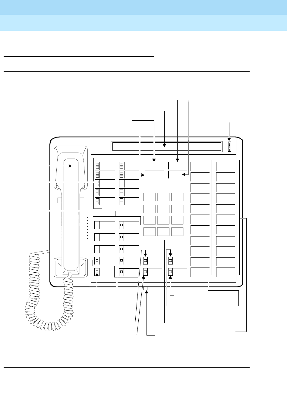
DEFINITYEnterpriseCommunicationsServerandSystem75andSystem85
Terminals and Adjuncts Reference
555-015-201 Issue 11
December 1999
The 7400 Series Voice Terminals
11-63The 7407D, Enhanced 7407D, and 7407 Plus Voice Terminals
11
The 7407D, Enhanced 7407D, and
7407 Plus Voice Terminals
Figure 11-17. The 7407D (7407D01B) Voice Terminal
Handset
123
456
789
ABC DEF
MNOJKLGHI
PRS TUV WXY
*
O#
Oper
Conference
Drop
Transfer
Hold
10 Call
2 Feature
Message
Speakerphone
Select
Microphone
Display Ring
1
2
3
4
5
6
7
Appearance/
Message Light
Speakerphone Button
Microphone Button
Calculator/
Display Button Dial Pad
Speakerphone
Volume Control
Feature
11 Dual-
11 Feature
Buttons
Display Viewing
Adjustment
Display
Transfer Button Hold Button
Conference Button
Drop Button
Ringer
Buttons
Buttons
terminal)
under voice
Control
Volume
Buttons
Function
Buttons
7 Display Control
Ring Button
Select
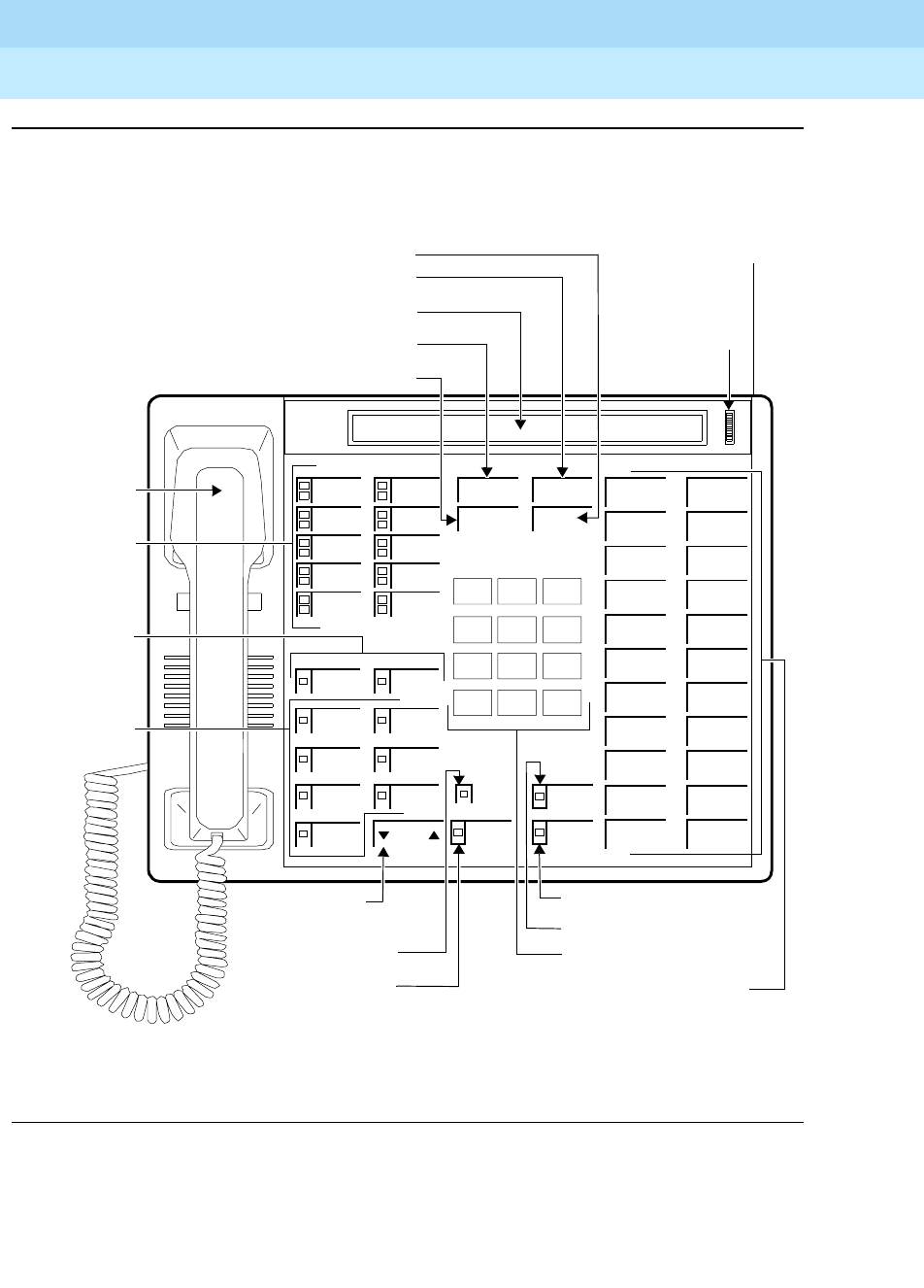
DEFINITYEnterpriseCommunicationsServerandSystem75andSystem85
Terminals and Adjuncts Reference
555-015-201 Issue 11
December 1999
The 7400 Series Voice Terminals
11-64The 7407D, Enhanced 7407D, and 7407 Plus Voice Terminals
11
Figure 11-18. The Enhanced 7407D (7407D02C) Voice Terminal
Volume
Handset
123
456
789
ABC DEF
MNOJKLGHI
PRS TUV WXY
*
O#
Oper
Conference
Drop
Transfer
Hold
10 Call
2 Feature
Message
Speaker
Select
Mute
4
Ring
1
2
3
5
6
7
Appearance/
Volume Control
Speaker Button
Mute Button
Message Light Dial Pad
Feature
22 Feature Buttons
Display Viewing
Adjustment
Display
Transfer Button
Hold Button
Conference Button
Drop Button
Buttons
Buttons
7Display
Select Ring Button
Speakerphone
Headset Adapter
Jack (on back of
voice terminal)
Button
Buttons
Control
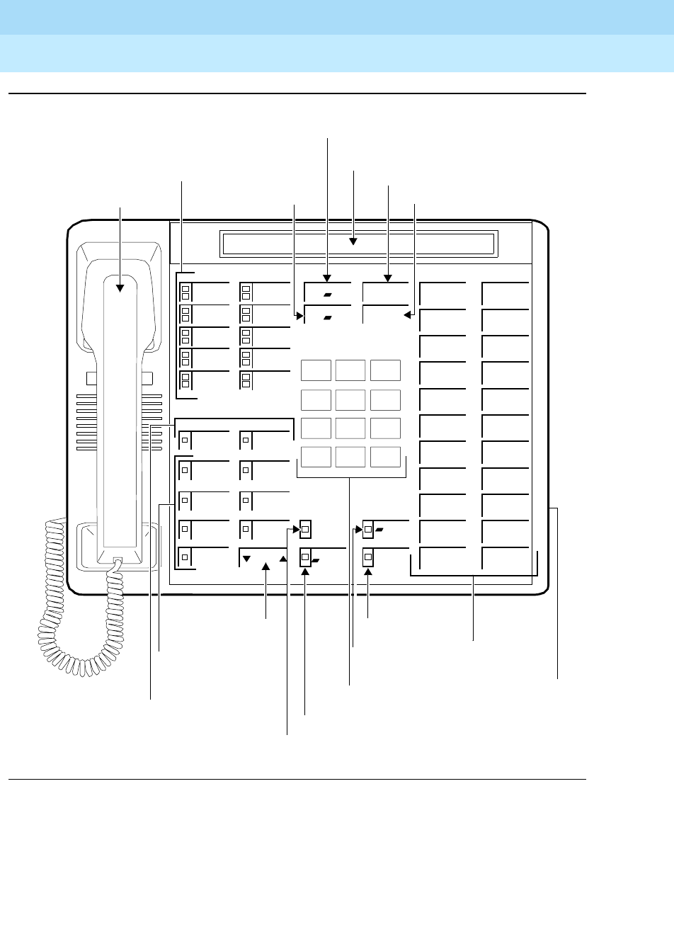
DEFINITYEnterpriseCommunicationsServerandSystem75andSystem85
Terminals and Adjuncts Reference
555-015-201 Issue 11
December 1999
The 7400 Series Voice Terminals
11-65The 7407D, Enhanced 7407D, and 7407 Plus Voice Terminals
11
Figure 11-19. The 7407 Plus (7407D02D) Voice Terminal
Volume
Handset
123
45 6
789
ABC DEF
MNOJKLGHI
PQRS TUV WXYZ
*
O#
Oper
Conference
Drop
Transfer
Hold
10 Call Appearance/
2 Feature Buttons
Speaker
Select
Mute
Message
1
2
3
4
5
6
7 Display Feature
Buttons
Mute Button
Select Button
Message Light
Dial Pad
Speaker/Reset
22 Feature
Buttons
Display
Transfer Button
Hold Button
Conference/Ring Button
Drop/Test Button
7
Volume Control
Button
Speakerphone/
Headset Adapter
Jack (on back
of voice
Ring
Test
Reset Spkr
terminal)
Feature Buttons
Spkr Button

DEFINITYEnterpriseCommunicationsServerandSystem75andSystem85
Terminals and Adjuncts Reference
555-015-201 Issue 11
December 1999
The 7400 Series Voice Terminals
11-66The 7407D, Enhanced 7407D, and 7407 Plus Voice Terminals
11
The 7407D, Enhanced 7407D, and 7407 Plus voice terminals are
multi-appearance digital voice terminals which provide digital voice, display, and
data capabilities (the latter with the 7400B Plus Data Module). There are three
versions of the 7407D voice terminal. A brief description of each of these versions
is listed below:
■The 7407D (the 7407D01B)—offers 10 call appearance/feature buttons,
each with a red in-use light and a green status light, four standard fixed
feature buttons (CONFERENCE, DROP, HOLD, and TRANSFER), three
fixed feature buttons with an associated light (CALCULATOR/SELECT
RING, SPEAKERPHONE, and MICROPHONE), nine programmable
feature buttons with lights (the two uppermost buttons can be used for
voice or display features, the lower seven for display features),
11 dual-function buttons, 22 programmable feature-only buttons without
lights, a Message light, a DISPLAY button that turns the display on and off,
personalized ringing, a built-in speakerphone, a 2-line by 40-character
liquid crystal display, and a built-in calculator. This voice terminal also
provides the user the flexibility of adding a data stand to provide data
communications. Data access can also be provided by the addition of the
PC/PBX Connection Card to any AT&T compatible PC or by use of a
7400B Plus Data Module. This set is AC powered.
■The Enhanced 7407D (the 7407D02C)—offers 10 call appearance buttons,
each with a red in-use light and green status light, four standard fixed
feature buttons (CONFERENCE, DROP, HOLD, and TRANSFER), three
fixed feature buttons with an associated light (SELECT RING, SPEAKER,
and MUTE), 22 programmable feature-only buttons without lights, nine
programmable feature buttons with one light each (the uppermost two
buttons can be used for voice or display features, the lower seven for
display features), a Message light, personalized ringing, a built-in
speakerphone, a connection for an adjunct speakerphone or headset, a
speakerphone with spokesman and Mute option, and a 2-line by
40-character “super-twist” liquid crystal display. Data access can be
provided by the addition of the PC/PBX Connection Card to any AT&T
compatible PC or by use of a 7400B Plus Data Module. This set is powered
from the switch.

DEFINITYEnterpriseCommunicationsServerandSystem75andSystem85
Terminals and Adjuncts Reference
555-015-201 Issue 11
December 1999
The 7400 Series Voice Terminals
11-67The 7407D, Enhanced 7407D, and 7407 Plus Voice Terminals
11
■The 7407 Plus (the 7407D02D)—offers 10 call appearance buttons, each
with a red in-use light and a green status light, four standard fixed feature
buttons (CONFERENCE, DROP, HOLD, and TRANSFER), three fixed
feature buttons with one light each (SELECT, SPEAKER/RESET SPKR,
and MUTE), nine feature buttons with one light each (the uppermost two
buttons can be used for voice or display features, the lower seven buttons
for display features), 22 flexible feature buttons with no lights, a Message
light, personalized ringing, a built-in speakerphone with a reset and
listen-only option, and a built-in 2-line by 40-character “super-twist” liquid
crystal display. Data access can be provided by the addition of the PC/PBX
Connection Card to any AT&T compatible PC or by use of a 7400B Plus
Data Module. This voice terminal is powered from the switch.
NOTE:
None of the 7407 voice terminals are being manufactured.
Applications
The 7407D, Enhanced 7407D, and 7407 Plus voice terminals can be used with
the DEFINITY Communications System Generic 1, Generic 2, and Generic 3, the
DEFINITY ECS, System 75, and System 85. Typical applications of the 7407D,
Enhanced 7407D, and the 7407 Plus voice terminal are managers, executives, or
secretaries who need the robust, 2-line by 40-character display capability or with
data terminals requiring a large number of features and lines.
Special Operational Characteristics
The 7407D (7407D01B) voice terminal has an R1/R2 single-option toggle switch
on the back of the stand; the Enhanced 7407D (7407D02C), and 7407 Plus
(7407D02D) voice terminals have a 3-option DIP switch that can be accessed
from the back of the stand, although, on both voice terminals only two of the
options can be used. The DIP switch options can be changed with a simple tool.
Switch Options for the 7407D and
Enhanced 7407D
The following list describes the settings on the toggle switch on the 7407D
(7407D01B) voice terminal and the DIP switch settings on the Enhanced 7407D
(7407D02C) voice terminals:
■Since the 7407D and the Enhanced 7407D have 2-line displays, the
single-option R1/R2 toggle switch on the 7407D voice terminal and Switch
1 on the DIP switch settings on the Enhanced 7407D voice terminal must
be activated according to the vintage of the supporting PBX.
The 7407D voice terminal option switch is shipped in the OFF position; the
Enhanced 7407D voice terminal is shipped with Switch 1 in the R2 position.
These positions are the correct setting for most PBXs.
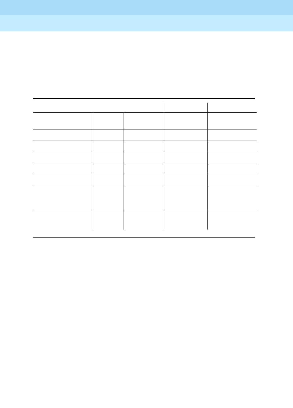
DEFINITYEnterpriseCommunicationsServerandSystem75andSystem85
Terminals and Adjuncts Reference
555-015-201 Issue 11
December 1999
The 7400 Series Voice Terminals
11-68The 7407D, Enhanced 7407D, and 7407 Plus Voice Terminals
11
Use the following table to determine your PBX’s release and version for
setting the following switches:
■The R1/R2 switch on the 7407D01B voice terminal
■Switch 1 on the 7407D02C voice terminal
■Switch 2 on the Enhanced 7407D (7407D02C) voice terminal controls the
Spokesman option. The microphone associated with the Speakerphone
can be disabled, which changes Speakerphone functionality to the
Spokesman function leaving the handset active.
The Enhanced 7407D voice terminal is shipped with Switch 2 in the
Speakerphone position (with the microphone enabled). This corresponds
to the OFF position.
Table 11-11. DIP Switch Settings on the 7407D and Enhanced 7407D
Voice Terminals
If the voice terminal is connected to: Set R1/R2 to: Set Switch 1 to:
System Release Version
Switch
Setting
Switch
Setting
System 75 1 1 R1 On
System 75 1 2 and above R2 Off
System 85 1 All R1 On
System 85 2 1 R1 On
System 85 2 2 and above R2 Off
DEFINITY G1 and
G3 and the
DEFINITY ECS
R1 Off
DEFINITY
Generic 2 R1 Off
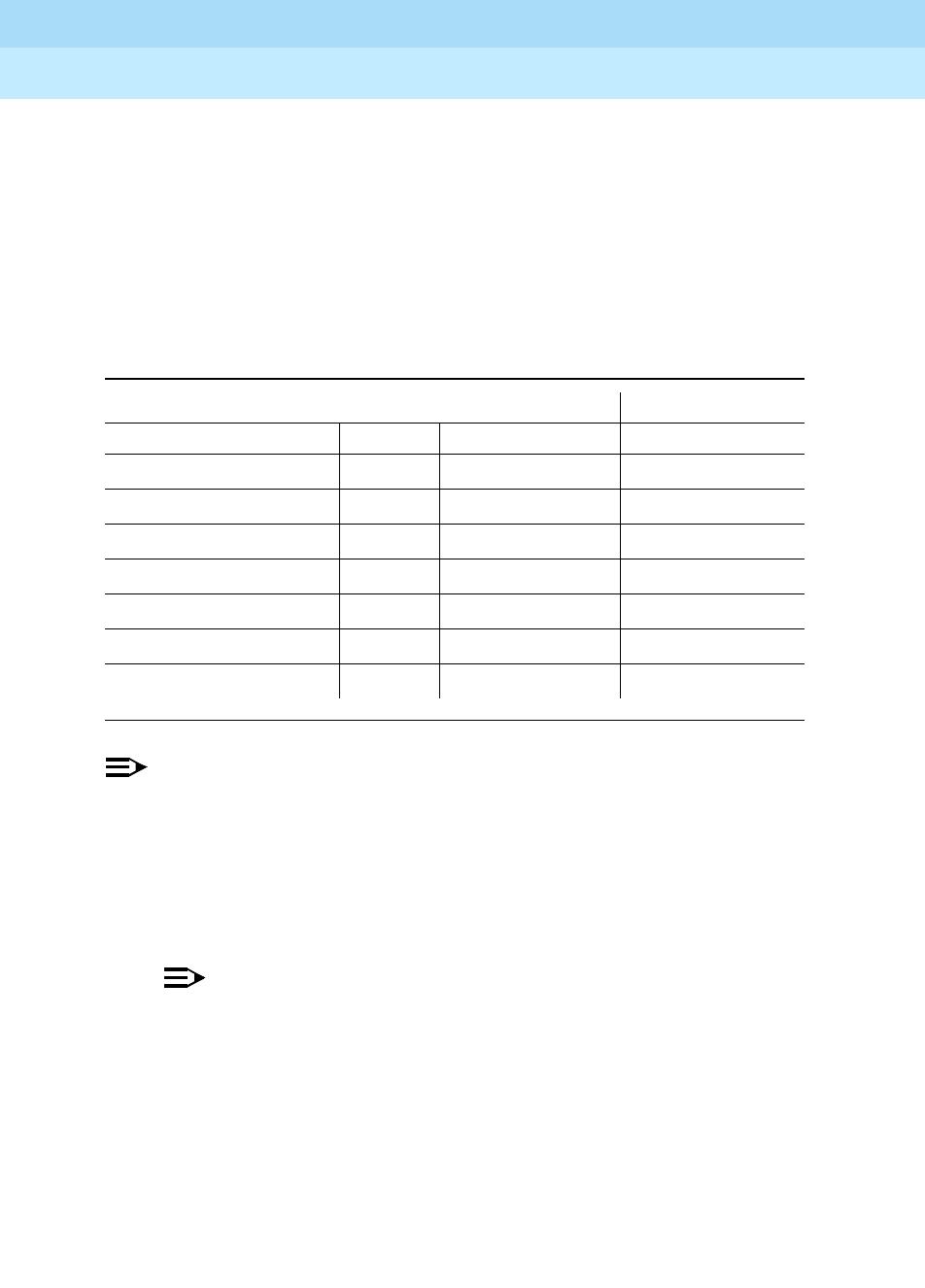
DEFINITYEnterpriseCommunicationsServerandSystem75andSystem85
Terminals and Adjuncts Reference
555-015-201 Issue 11
December 1999
The 7400 Series Voice Terminals
11-69The 7407D, Enhanced 7407D, and 7407 Plus Voice Terminals
11
DIP Switch Options for the 7407 Plus
For the 7407 Plus (7407D02D) voice terminal, the 3-position DIP switch should be
set in the following way:
■Initially, Switch 1 is set to the OFF position. However, according to the
release and version of the System 75 or 85 to which the voice terminal is
connected, you may need to change Switch 1 to the ON position. Check
the following table for this information.
NOTE:
If this switch is not set correctly, the display will not work properly. For
example, the call appearance display, usually on the top line, may appear on
the second line instead.
■Switch 2 is set for the Speakerphone feature (to the OFF position). If the
voice terminal is to be set for the Speaker (listen-only) feature, set Switch 2
to the ON position.
NOTE:
In order to allow the system to recognize this change in the setting,
you must disconnect the voice terminal and then plug it in again.
■Switch 3, on the 7407 Plus voice terminal, is not to be used at this time.
Table 11-12. DIP Switch Settings on the 7407 Plus Voice Terminal
If the voice terminal is connected to: Set Switch 1 to:
System Release Version Switch Setting
System 75 1 1 On
System 75 1 2 and above Off
System 85 1 All On
System 85 2 1 On
System 85 2 2 and above Off
DEFINITY Generic 1 Off
DEFINITY Generic 2 Off

DEFINITYEnterpriseCommunicationsServerandSystem75andSystem85
Terminals and Adjuncts Reference
555-015-201 Issue 11
December 1999
The 7400 Series Voice Terminals
11-70The 7407D, Enhanced 7407D, and 7407 Plus Voice Terminals
11
Physical Features
Dimensions
NOTE:
The dimensions given here for the 7407 voice terminals are approximate.
Width = 12 inches
Depth (front to back) = 8-1/2 inches
Height (maximum with handset in place) = 6-1/4 inches
Thickness of housing = 1-1/2 inches
Features
Four Standard Fixed Feature Buttons
■CONFERENCE or CONFERENCE/RING button
■DROP or DROP/TEST button
■TRANSFER button
■HOLD button
CALCULATOR/SELECT RING button
(on 7407D only)
This button is only on the 7407D (7407D01B) voice terminal. It toggles the 11
dual-function buttons between calculator functions on the left side of the buttons
(the CALCULATOR/SELECT RING light is on) and features administered on the
right side of the buttons (the CALCULATOR/SELECT RING light is off). The button
can also be used with the PR (Personalized Ring) button to select one of eight
possible personalized ringing patterns.
SELECT RING button (on Enhanced 7407D only)
This button is on the Enhanced 7407D (7407D02C) voice terminal. It toggles
between the Select Ring function (selecting a personalized ringing pattern from
eight available patterns) and Self-Test function (tests the lights, ringer, and
display).

DEFINITYEnterpriseCommunicationsServerandSystem75andSystem85
Terminals and Adjuncts Reference
555-015-201 Issue 11
December 1999
The 7400 Series Voice Terminals
11-71The 7407D, Enhanced 7407D, and 7407 Plus Voice Terminals
11
SELECT button (on the 7407 Plus only)
The 7407 Plus (7407D02D) voice terminal has a SELECT button which can be
used in three different ways:
■Used with the DROP/TEST button to initiate a self-test of your voice
terminal (which tests the lights, tone ringer, and display)
■Used with the CONFERENCE/RING button to select your own
personalized ring from among eight available patterns
■Used with the SPEAKER/RESET SPKR button to perform an acoustic test
of the environment and adjust the speakerphone to the surrounding
acoustic environment for optimal performance
Message light
The Message light goes on when a message is left for the user. It goes off when
the user retrieves the message or when the message is erased. On the 7407D
(7407D01B) voice terminal, the Message light is green; on the Enhanced 7407D
and the 7407 Plus voice terminals, the Message light is red.
Call Appearance/Feature Buttons
The 7407D, Enhanced 7407, and 7407 Plus voice terminals have 10 call
appearance/feature buttons.
Feature-only Buttons on the 7407D (7407D01B)
The 7407D (7407D01B) voice terminal has the following sets of feature buttons:
■11 feature buttons in the rightmost column, all without lights, which can be
used for features only.
■11 dual-function buttons without lights, in the second column from the right
are used as dual-function (calculator) buttons.
— When the CALCULATOR/SELECT RING button is active (the green
light next to the CALCULATOR/SELECT RING button is on), the top
button, labeled “PR,” is in the Select Ring mode for programming a
personalized ringing pattern; the lower 10 buttons have standard
hand calculator functions (which are labeled on the left of the
button). These button assignments cannot be changed.
— When the CALCULATOR/SELECT RING button is off (the green
light next to the CALCULATOR/SELECT RING button is off), all 11
of these dual-function buttons have optional features (which are
labeled on the right of the button). These features are assigned by
the system manager.
■nine feature buttons on the bottom left, each with a green light. The two
upper buttons are for voice features. The lower seven buttons are for
display control functions and/or features.

DEFINITYEnterpriseCommunicationsServerandSystem75andSystem85
Terminals and Adjuncts Reference
555-015-201 Issue 11
December 1999
The 7400 Series Voice Terminals
11-72The 7407D, Enhanced 7407D, and 7407 Plus Voice Terminals
11
Feature-only Buttons on the Enhanced 7407D (7407D02C)
The Enhanced 7407D (7407D02C) voice terminal has the following sets of feature
buttons:
■22 feature buttons in the rightmost column, all without lights
■nine feature buttons on the bottom left, each with a green status light. The
two upper buttons are for voice features. The lower seven buttons are for
display control functions and/or features.
Feature-only Buttons on the 7407 Plus (7407D02D)
The 7407 Plus (7407D02D) voice terminal has the following sets of feature
buttons:
■22 feature buttons in the rightmost column, all without lights
■nine feature buttons on the bottom left, each with a green light. The two
upper buttons are for voice features. The lower seven buttons are for
display control functions and/or features.
Speakerphone (Listen and Speak) Feature
The 7407D, Enhanced 7407D, and 7407 Plus voice terminals are equipped with a
built in speakerphone. The Speakerphone capability allows a user to engage in a
hands-free 2-way conversation with the far-end party. The speakerphone can be
turned off or on (use the SPEAKERPHONE button on the 7407D, the SPEAKER
button on the Enhanced 7407D, and the SPEAKER/RESET SPKR button on the
7407 Plus), can be muted (use the MICROPHONE button on the 7407D; use the
MUTE button on the Enhanced 7407D and 7407 Plus), and the speakerphone
volume can be controlled, on the 7407D, with a slide switch, or on the Enhanced
7407D and 7407 Plus, with the VOLUME “arrow” button.
The 7407 Plus (7407D02D) voice terminal has an S201A-type speakerphone
which allows the user to adjust the speakerphone for optimal performance. By
pressing the SELECT button and then the SPEAKER/RESET SPKR button (if the
voice terminal is set for the Speakerphone feature), the user hears a set of tones
as the speakerphone performs an acoustic test of the environment. When the
tones stop, the speakerphone has finished adjusting itself and is ready for use.
The user should reset the speakerphone whenever the voice terminal is moved to
another place (even in the same room), whenever the green light next to the
SPEAKER/RESET SPKR button is fluttering, and in the unlikely event that the
speakerphone is making a squealing sound.
Speaker (Listen-only) Feature
The 7407 Plus voice terminal can be optioned for the Speakerphone (listen and
speak) or the Speaker (listen-only) feature. The Enhanced 7407D voice terminal
can be set for the Speakerphone or the Spokesman feature. (With the latter
feature, the user can use the speaker and the handset simultaneously.) In order to
turn on and off the speaker, use the SPEAKER button on the Enhanced 7407D, or
the SPEAKER/RESET SPKR button on the 7407 Plus.

DEFINITYEnterpriseCommunicationsServerandSystem75andSystem85
Terminals and Adjuncts Reference
555-015-201 Issue 11
December 1999
The 7400 Series Voice Terminals
11-73The 7407D, Enhanced 7407D, and 7407 Plus Voice Terminals
11
The Speaker (listen-only) and Spokesman capability allows a user to engage in a
one-way conversation with the far-end. Specifically, the user can only listen to the
far-end; the user is not able to transmit his voice over the speaker. To speak with
the far-end, the user must use the handset.
With the Enhanced 7407D voice terminal, the handset and Speaker capability can
be used simultaneously. If you are using a 7407 Plus, you ca
nnot
use the handset
and speaker at the same time.
These voice terminals are shipped with the Speakerphone setting in place, but the
necessary DIP switch setting can be changed so that the voice terminal operates
with the Speaker or Spokesman feature instead.
MICROPHONE button (on 7407D only)
On the 7407D (7407D01B) voice terminal, the MICROPHONE button turns the
speakerphone microphone on and off.
MUTE button (on the Enhanced 7407D and
7407 Plus)
On the Enhanced 7407D (7407D02C) and 7407 Plus (7407D02D) the red MUTE
button disables the transmitter of the speakerphone or the handset depending on
which is activated at that time.
VOLUME control button (on Enhanced 7407D and 7407 Plus)
The Enhanced 7407D (7407D02C) and 7407 Plus (7407D02D) voice terminals
have a VOLUME “arrow” button. This button has a double function. When there is
a call active on the speaker or speakerphone, the VOLUME button controls the
volume of the speakerphone; at all other times, the button controls the volume of
the tone ringer.
When the user sets the volume for the speaker or the tone ringer, the display on
the voice terminal shows a “bar array” that indicates the volume setting.
Self-Test (on Enhanced 7407 and 7407 Plus)
The 7407D, Enhanced 7407D (7407D02C), and 7407 Plus (7407D02D) voice
terminals are equipped with a self-test.
On the 7407D (7407D01B) voice terminal, the user can test the lights, ringer, and
display by pressing the Self-Test button under the left side of the set.
On the Enhanced 7407D (7407D02C) voice terminal, the user presses the
SELECT RING button and then the DROP button in order to initiate a self-test of
the voice terminal. On the 7407 Plus (7407D02D) voice terminal, the user presses
the SELECT button and then the DROP/TEST button to start the voice terminal
self-test.

DEFINITYEnterpriseCommunicationsServerandSystem75andSystem85
Terminals and Adjuncts Reference
555-015-201 Issue 11
December 1999
The 7400 Series Voice Terminals
11-74The 7407D, Enhanced 7407D, and 7407 Plus Voice Terminals
11
During the self-test, all the lights go on, the ringer sounds, and the display
character positions are lit. On the Enhanced 7407D and the 7407 Plus voice
terminals, the self-test ends when the user releases the DROP or DROP/TEST
button. On the 7407D voice terminal, the lights stay lit for a few seconds and then
go off.
Display
The 7407D, Enhanced 7407D, and 7407 Plus voice terminals are equipped with a
built-in, 2-line, 40-character per line, liquid crystal display. The 7407D voice
terminal has a standard, “twisted,” pneumatic display; the Enhanced 7407D and
7407 Plus voice terminals have a “super-twist” display.
DISPLAY button (on 7407D only)
This button is found only on the 7407D (7407D01B) voice terminal. It turns the
display on and off.
Display Adjustment Control (on 7407D and Enhanced 7407D)
On the 7407D (7407D01B) and Enhanced 7407D (7407D02C) voice terminals
there is a thumbwheel which adjusts the viewing contrast of the display.
Other Physical Features
Handset
The 7407D, Enhanced 7407D, and 7407 Plus voice terminals are equipped with
an R-type handset.
Dial pad
The 7407D, Enhanced 7407D, and 7407 Plus voice terminals are equipped with a
12-button touch-tone dial pad. On the 7407 Plus (7407D02D) voice terminal the
letters “Q” and “Z” have been added to the appropriate dial pad keys for directory
access, and the “5” button on the dial pad has raised bars for visually-impaired
users.
Jacks
The 7407D (7407D01B) voice terminal’s housing contains a Handset cord jack
just under the left side of the housing, and a Line jack on the back of the voice
terminal. There is an RS-232C connector on the optional data stand.
The Enhanced 7407D (7407D02C) and the 7407 Plus (7407D02D) voice
terminals’ housing contains a Handset cord jack just under the left side of the
housing and a Line jack and Speakerphone/headset adapter jack on the back of
the voice terminal.

DEFINITYEnterpriseCommunicationsServerandSystem75andSystem85
Terminals and Adjuncts Reference
555-015-201 Issue 11
December 1999
The 7400 Series Voice Terminals
11-75The 7407D, Enhanced 7407D, and 7407 Plus Voice Terminals
11
Cords
Three cords are supplied with the 7407D (7407D01B) voice terminal: a coiled
9-foot modular handset cord, 7-foot modular line cord and an AC power cord.
Two cords are supplied with the Enhanced 7407D (7407D02C) and 7407 Plus
(7407D02D) voice terminal: a coiled 9-foot modular handset cord and a 7-foot
modular line cord.
Optional longer cords are available: a 12-foot handset cord, 14-foot and 25-foot
line cords.
Ringing
The 7407D, Enhanced 7407D, and 7407 Plus voice terminals have electronic tone
ringing that can be personalized with eight possible ringing patterns selected with
the Select Ring feature. On the Enhanced 7407D (7407D02C) and 7407 Plus
voice terminals, the ringing volume of the second call appearance is automatically
set to muted ringing.
On the 7407D (7407D01B) voice terminal, the volume control is on the left side of
the housing.
On the Enhanced 7407D (7407D02C) and 7407 Plus (7407D02D) voice
terminals, the volume is controlled by the VOLUME control button on the front of
the voice terminal. The left side of the button lowers the volume; the right side of
the button raises the volume. If a call is active on the speaker or speakerphone,
the VOLUME control button adjusts the speaker or speakerphone. At all other
times, the VOLUME control button controls the loudness of the tone ringer. The
display screen shows a “bar array” to reflect the selected volume.
Mounting Options
The 7407D (7407D01B) comes equipped with a nonadjustable desk stand or an
optional data stand.
The Enhanced 7407D (7407D02CB) and 7407 Plus (7407D02D) voice terminals
come equipped with a nonadjustable desk stand. The optional data stand cannot
be used with these voice terminals.
Color Options
The 7407D, Enhanced 7407D, and 7407 Plus voice terminals are available in
black and misty cream.
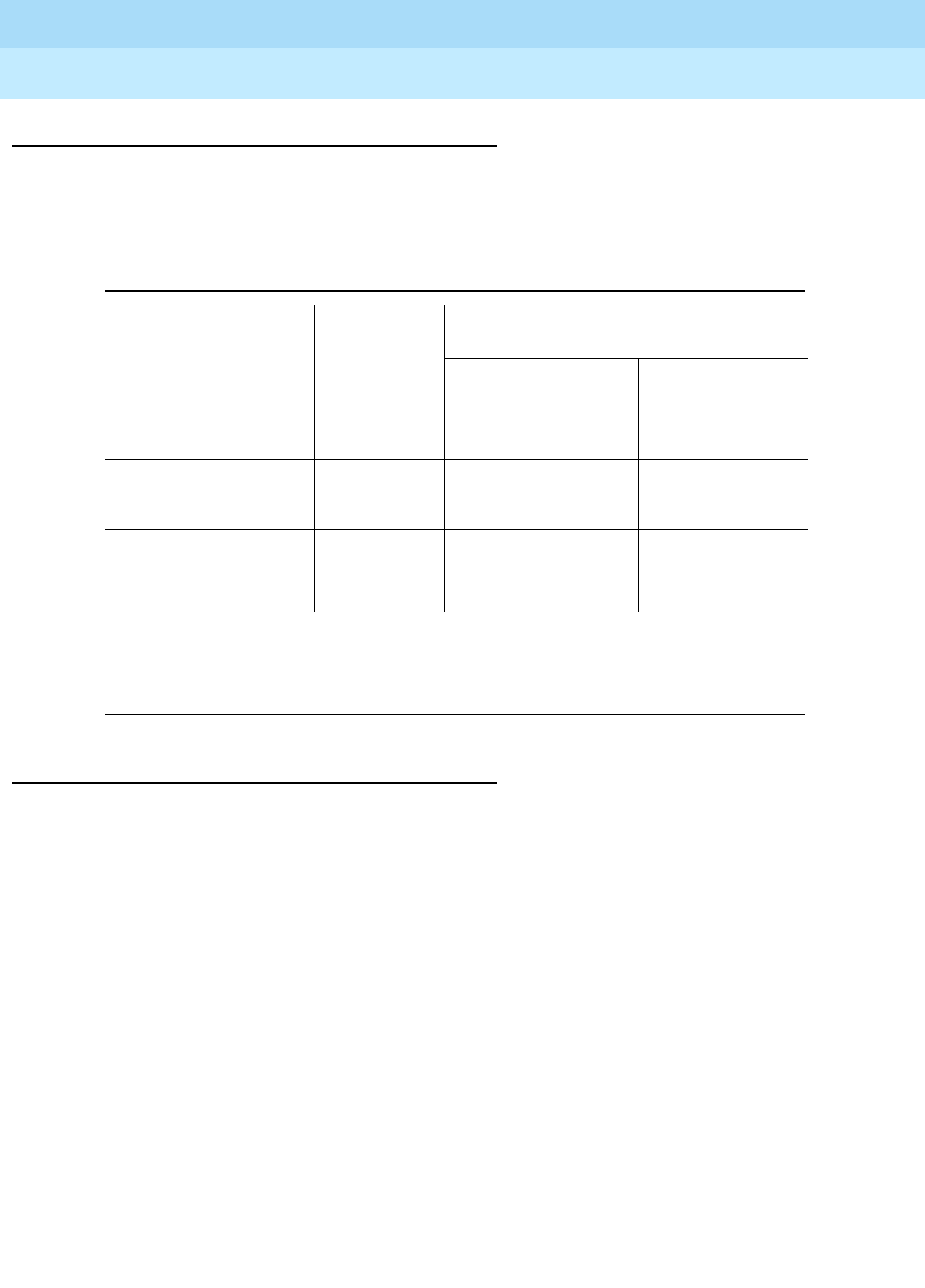
DEFINITYEnterpriseCommunicationsServerandSystem75andSystem85
Terminals and Adjuncts Reference
555-015-201 Issue 11
December 1999
The 7400 Series Voice Terminals
11-76The 7407D, Enhanced 7407D, and 7407 Plus Voice Terminals
11
Distance Limitations
The maximum distances the 7407D, Enhanced 7407D, and 7407 Plus voice
terminals can be located from the system cabinet are shown in the table below.
Note:
These ranges can be extended to 5,000 feet (1524 m) for 24 AWG wire and 4,000 feet
(1219 m) for 26 AWG wire with the use of a Data Link Protector. Refer to the Exposed Port
Protection section earlier in this manual.
Power Requirements
The 7407D (7407D01B) voice terminal requires a 3-prong 115-volt AC outlet for
power. (This outlet cannot be under the control of a wall switch.) A built-in power
supply converts the 115 volts to the DC power required. A 3-wire AC power cord is
provided with the voice terminal. No external power adjuncts are required.
The Enhanced 7407D (7407D02C) and 7407 Plus (7407D02D) voice terminals
receive power from the system and do not require any external power supply.
Additional power is required when these voice terminals are equipped with any
adjuncts. Refer to the Adjunct Power section earlier in this manual.
Table 11-13. Distance Limitations for the 7407D, Enhanced 7407D, and
7407 Plus Voice Terminals
System Port Board
Nominal Maximum Range in Feet
(Meters) (See Note)
24 AWG 26 AWG
System 85 SN270B
TN754
3,400 (1,034)
3,400 (1,034)
2,200 (671)
2,200 (671)
DEFINITY G2 SN270B
TN754
3,400 (1,034)
3,400 (1,034)
2,200 (671)
2,200 (671)
DEFINITY G1 and
G3, DEFINITY ECS,
and System 75
TN754 3,400 (1,034) 2,200 (671)
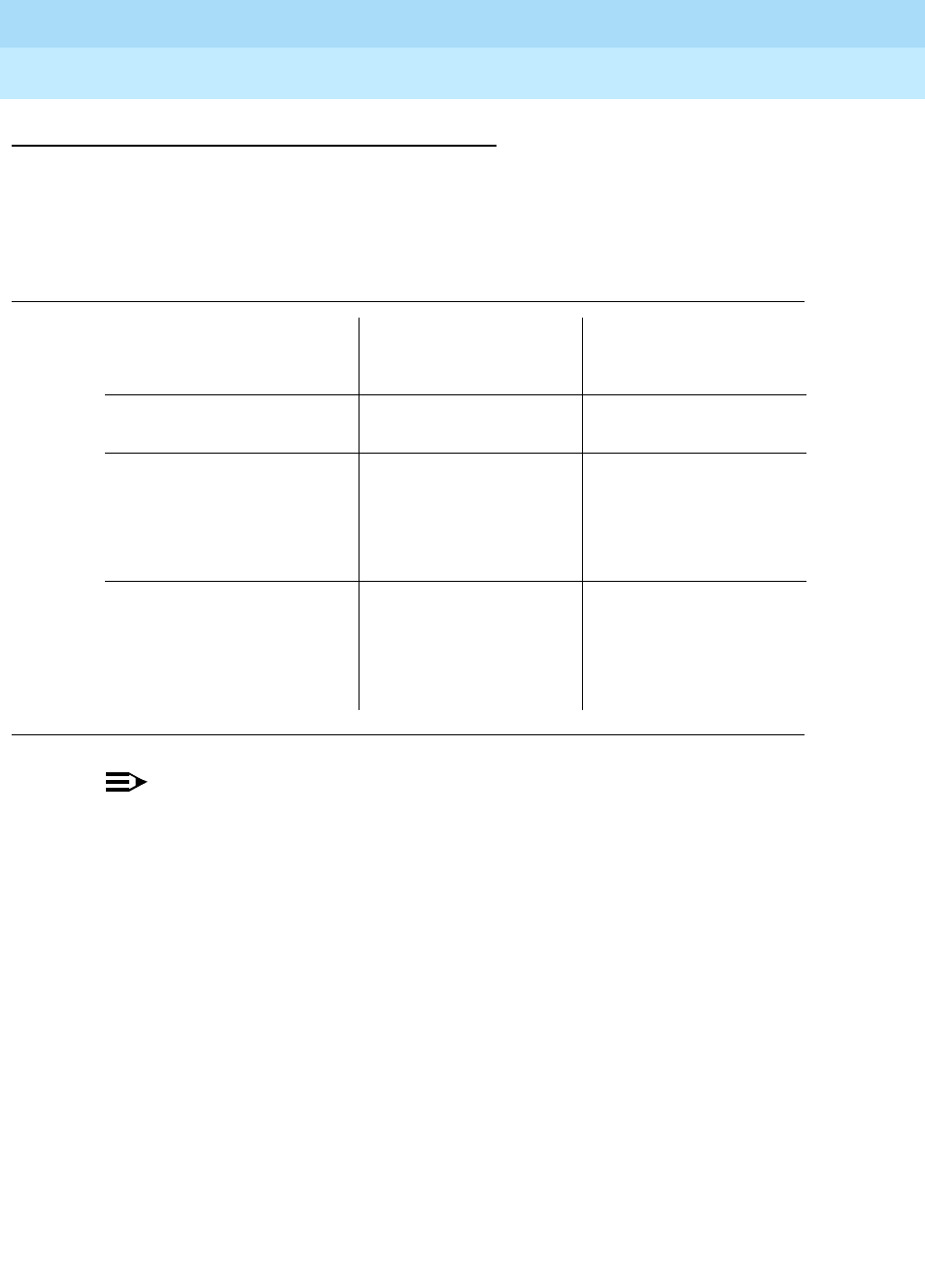
DEFINITYEnterpriseCommunicationsServerandSystem75andSystem85
Terminals and Adjuncts Reference
555-015-201 Issue 11
December 1999
The 7400 Series Voice Terminals
11-77The 7407D, Enhanced 7407D, and 7407 Plus Voice Terminals
11
Switch Administration
Aliasing
The 7407 voice terminals must be aliased in the following way:
NOTE:
On the 7407D (7407D01B) voice terminal, the second column of 11 buttons
from the right are dual-function buttons. On the left side of the button, there
is a fixed calculator (or personalized ring) feature. (These
cannot
be
reassigned.) These calculator/select ring features can be used when the
CALCULATOR/SELECT RING button is active, and the button light is on.
The features labeled on the right side of these 11 dual-function buttons
can be
administered with system features. These administered features can be used
when the CALCULATOR/SELECT RING button is not active, and the button light
is off.
Button Numbering
The following button diagrams of the 7407D and the 7407 Plus voice terminals will
help you administer these voice terminals on a System 75, a DEFINITY G1 and
G3, a DEFINITY ECS, and on a System 85 and a DEFINITY G2. Figures 11-20
and 11-21 refer to the 7407D; Figures 11-22 and 11-23 refer to the Enhanced
7407D voice terminal; Figures 11-24 and 11-25 refer to the 7407 Plus voice
terminal.
Table 11-14. Administering the 7407D, Enhanced 7407D, and 7407 Plus Voice Terminals
If you are administering
this system:
For this type of voice
terminal:
The voice terminal
must be
administered as:
System 75, R1V1 and
System 85, R2V1 7407D Enhanced
7407D 7407 Plus a 7405D with digital
display module
System 75, R1V2 or
above, DEFINITY G1 and
G3, DEFINITY ECS,
System 85, R2V2 or
above, and DEFINITY G2
7407D itself
System 75, R1V2 or
above, DEFINITY G1 and
G3, DEFINITY ECS,
System 85, R2V2 or
above, and DEFINITY G2
Enhanced 7407D 7407
Plus a 7407D voice terminal
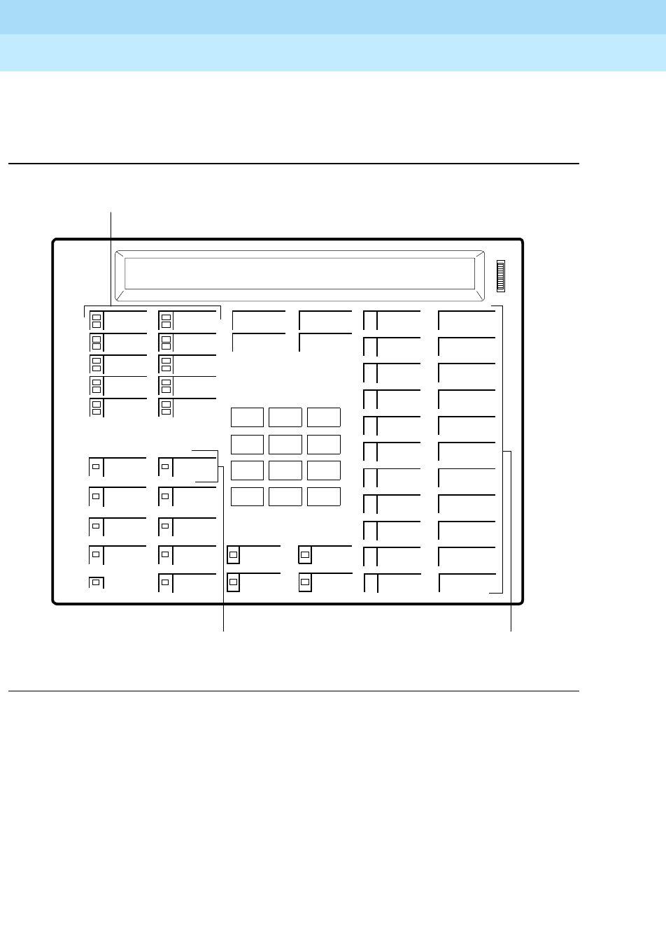
DEFINITYEnterpriseCommunicationsServerandSystem75andSystem85
Terminals and Adjuncts Reference
555-015-201 Issue 11
December 1999
The 7400 Series Voice Terminals
11-78The 7407D, Enhanced 7407D, and 7407 Plus Voice Terminals
11
If you need more information, refer to
DEFINITY Communications System
Generic 3 Implementation
, 555-230-653, and
DEFINITY Communications System
Generic 2 Administration of Features and Hardware
, 555-104-507.
Figure 11-20. Button Numbering for Administering the 7407D (7407D01B)
Voice Terminal Connected to a System 75, a DEFINITY G1 or G3,
or a DEFINITY ECS
123
456
789
ABC DEF
MNOJKLGHI
PRS TUV WXY
*
O#
Oper
Conference
Drop
Transfer
Hold
Message
Speakerphone
Calculator
Microphone
Display
Select Ring
1
2
3
Display 4
Display 5
Display 6
Display 7
Feature Button
Assignments 3 - 24
Display 1
Display 2
1
4
5
6
7
8
9
10
Display 3
3
4
5
6
7
8
9
10
11
12
13
14
15
16
17
18
19
20
21
22
23
24
P
R
C/
CE
M
R
M
M
+
X
+
-
+
3
-
=
Feature Button
Assignments 1 and 2
Button Assignments 1 - 10
2
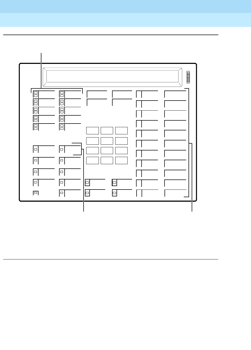
DEFINITYEnterpriseCommunicationsServerandSystem75andSystem85
Terminals and Adjuncts Reference
555-015-201 Issue 11
December 1999
The 7400 Series Voice Terminals
11-79The 7407D, Enhanced 7407D, and 7407 Plus Voice Terminals
11
Figure 11-21. Button Numbering for Administering the 7407D (7407D01B) Voice
Terminal Connected to a System 85 or a DEFINITY G2
123
456
789
ABC DEF
MNOJKLGHI
PRS TUV WXY
*
O#
Oper
Conference
Drop
Transfer
Hold
Message
Speakerphone
Calculator
Microphone
Display
Select Ring
13
4
5
Display 4
Display 5
Display 6
Display 7
Feature Button
Assignments 15 - 36
Display 1
Display 2
3
6
7
8
9
10
11
12
Display 3
15
16
17
18
19
20
21
22
23
24
25
26
27
28
29
30
31
32
33
34
35
36
P
R
C/
CE
M
R
M
M
+
X
+
-
+
3
-
=
Feature Button
Assignments 13 and 14
Button Assignments 3 - 12
14
NOTE: The Hold Button is Button #1.
The Message Light is Button #2.
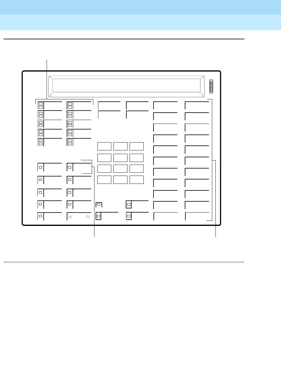
DEFINITYEnterpriseCommunicationsServerandSystem75andSystem85
Terminals and Adjuncts Reference
555-015-201 Issue 11
December 1999
The 7400 Series Voice Terminals
11-80The 7407D, Enhanced 7407D, and 7407 Plus Voice Terminals
11
Figure 11-22. Button Numbering for Administering the Enhanced 7407D (7407D02C)
Voice Terminal Connected to a System 75, a DEFINITY G1 or G3, or a
DEFINITY ECS
123
456
789
ABC DEF
MNOJKLGHI
PRS TUV WXY
*
O#
Oper
Conference
Drop
Transfer
Hold
Message
Speaker Mute
Select
1
2
3
Display 5
Display 6
Display 7
Volume
Feature Button
Assignments 3 - 24
Display 1
Display 2
1
4
5
6
7
8
9
10
Display 3
3
4
5
6
7
8
9
10
11
12
13
14
15
16
17
18
19
20
21
22
23
24
Feature Button
Assignments 1 and 2
Button Assignments 1 - 10
2
Ring
Display 4
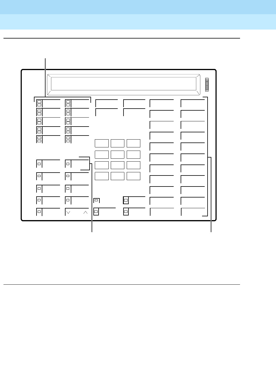
DEFINITYEnterpriseCommunicationsServerandSystem75andSystem85
Terminals and Adjuncts Reference
555-015-201 Issue 11
December 1999
The 7400 Series Voice Terminals
11-81The 7407D, Enhanced 7407D, and 7407 Plus Voice Terminals
11
Figure 11-23. Button Numbering for Administering the Enhanced 7407D (7407D02C)
Voice Terminal Connected to a System 85 or a DEFINITY G2
Message
Speaker Mute
Select
Ring
123
456
789
ABC DEF
MNOJKLGHI
PRS TUV WXY
*
O#
Oper
Conference
Drop
Transfer
Hold
13
4
5
Display 5
Display 6
Display 7
Feature Button
Assignments 15 - 36
Display 1
Display 2
3
6
7
8
9
10
11
12
Display 3
15
16
17
18
19
20
21
22
23
24
25
26
27
28
29
30
31
32
33
34
35
36
Feature Button
Assignments 13 and 14
Button Assignments 3 - 12
14
Volume
Display 4
NOTE: The Hold Button is Button #1.
The Message Light is Button #2.
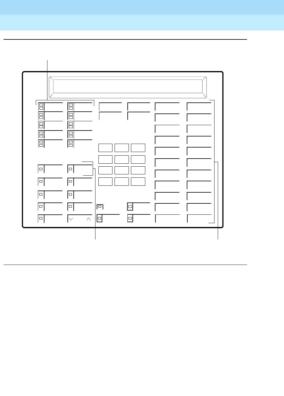
DEFINITYEnterpriseCommunicationsServerandSystem75andSystem85
Terminals and Adjuncts Reference
555-015-201 Issue 11
December 1999
The 7400 Series Voice Terminals
11-82The 7407D, Enhanced 7407D, and 7407 Plus Voice Terminals
11
Figure 11-24. Button Numbering for Administering the 7407 Plus Voice Terminal
Connected to a System 75, a DEFINITY G1 or G3, or a DEFINITY ECS
123
456
789
ABC DEF
MNOJKLGHI
PRS TUV WXY
*
O#
Oper
Conference
Drop
Transfer
Hold
Message
Speaker Mute
Select
1
2
3
Display 5
Display 6
Display 7
Volume
Feature Button
Assignments 3 - 24
Display 1
Display 2
1
4
5
6
7
8
9
10
Display 3
3
4
5
6
7
8
9
10
11
12
13
14
15
16
17
18
19
20
21
22
23
24
Feature Button
Assignments 1 and 2
Button Assignments 1 - 10
2
Display 4
Reset/Spkr
Test
Ring
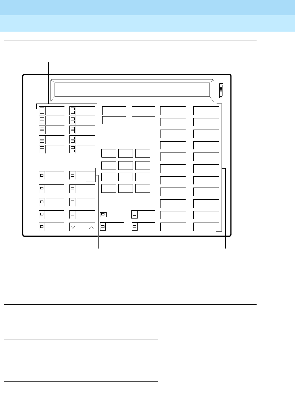
DEFINITYEnterpriseCommunicationsServerandSystem75andSystem85
Terminals and Adjuncts Reference
555-015-201 Issue 11
December 1999
The 7400 Series Voice Terminals
11-83The 7407D, Enhanced 7407D, and 7407 Plus Voice Terminals
11
Figure 11-25. Button Numbering for Administering the 7407 Plus Voice Terminal
Connected to a System 85 or a DEFINITY G2
Power Failure Operation
The 7407D, Enhanced 7407D, and 7407 Plus voice terminals cannot be used as
an emergency station during power failure transfer conditions.
FCC Registration
These voice terminals are FCC-registered along with the switch (as a system), but
do not have a separate FCC registration label.
Message
Speaker Mute
Select
Ring
123
456
789
ABC DEF
MNOJKLGHI
PRS TUV WXY
*
O#
Oper
Conference
Drop
Transfer
Hold
13
4
5
Display 5
Display 6
Display 7
Feature Button
Assignments 15 - 36
Display 1
Display 2
3
6
7
8
9
10
11
12
Display 3
15
16
17
18
19
20
21
22
23
24
25
26
27
28
29
30
31
32
33
34
35
36
Feature Button
Assignments 13 and 14
Button Assignments 3 - 12
14
Volume
Display 4
NOTE: The Hold Button is Button #1.
The Message Light is Button #2.

DEFINITYEnterpriseCommunicationsServerandSystem75andSystem85
Terminals and Adjuncts Reference
555-015-201 Issue 11
December 1999
The 7400 Series Voice Terminals
11-84The 7407D, Enhanced 7407D, and 7407 Plus Voice Terminals
11
UL and CSA Approval
These voice terminals have been tested and have met the Underwriters
Laboratories (UL) Standards UL 1459. In addition, the Enhanced 7407D and the
7407 Plus voice terminals have also met the Canadian Standards Association
(CSA) Standards CSA-C22.2 No.225-M90.
Hearing Aid Compatible
These voice terminals are compatible with the inductively coupled hearing aids
prescribed by the FCC.
7407D/Enhanced 7407D Equipment PECs and
Comcodes
The 7407D (7407D01B) and Enhanced 7407D (7407D02C) voice terminals and
optional components can be ordered with the following PECs and Comcodes:
■Basic 7407D01B Voice Terminal
PEC: 3180-IDT (Black=COL09; Misty Cream=COL22)
Comcode: Black=103983904; Misty Cream=103983938
■Basic 7407D02C Voice Terminal
PEC: 3180-PPS (Black=COL09; Misty Cream=COL22)
Comcode: Black=105733521; Misty Cream=105733539
■Handset
Comcode: Black=105519086; Misty Cream=105520787
■Handset cord (9 feet)
Comcode: Black=105635429; Misty Cream=105635437
■Handset cord (12 feet)
PEC: 2725-01L (Black= COL09; Misty Cream=COL22)
Comcode: Black=102401445; Misty Cream=104211339
■Line cord (7 feet, silver)
Comcode: 103786778
■Line cord (14 feet, silver)
PEC: 2725-07N COL18
Comcode: 103786802
■Line cord (25 feet, silver)
PEC: 2725-07S COL18
Comcode: 103786828

DEFINITYEnterpriseCommunicationsServerandSystem75andSystem85
Terminals and Adjuncts Reference
555-015-201 Issue 11
December 1999
The 7400 Series Voice Terminals
11-85The 7407D, Enhanced 7407D, and 7407 Plus Voice Terminals
11
■Display Bezel
Comcode: Black=846151876; Misty Cream=846151884
■Button designation card
PEC: 81004 (Package of 25)
Single Comcode: 846342038
Pack of 25 Comcode: 846342046
Tractor Feed Comcode: 846342020
7407 Plus Equipment PECs and Comcodes
The 7407 Plus (7407D02D) voice terminal and optional components can be
ordered with the following PECs and Comcodes:
■Basic 7407D02D Voice Terminal
PEC: 3180-PLS (Black=COL09; Misty Cream=COL22)
Comcode: Black=106281520; Misty Cream=106281538
■Handset
Comcode: Black=105519086; Misty Cream=105520787
■Handset cord (9 feet)
Comcode: Black=105635429; Misty Cream=105635437
■Line cord (7 feet)
Comcode: 103786778
■Line cord (14 feet, silver)
PEC: 2725-07N COL18
Comcode: 103786802
■Line cord (25 feet, silver)
PEC: 2725-07S COL18
Comcode: 103786828
■Button designation card
PEC: 81004 (Package of 25)
Comcode: (Single card) Black=846604791; Misty Cream=846604809
Comcode: (Pack of 25 Sheets) Black=846692333; Misty
Cream=846692325
Comcode: (Tractor Feed, 200 Sheets) Black=846604817: Misty
Cream=846604825

DEFINITYEnterpriseCommunicationsServerandSystem75andSystem85
Terminals and Adjuncts Reference
555-015-201 Issue 11
December 1999
The 7400 Series Voice Terminals
11-86The 7407D, Enhanced 7407D, and 7407 Plus Voice Terminals
11
Adjuncts
The following adjuncts can be used with these voice terminals:
NOTE:
Any adjunct equipment connected to the 7407 sets needs auxiliary power,
except for the 7400B Plus Data Module, which is AC powered.
■S101A Speakerphone (7407D02C and 740702D)
■S201A Speakerphone (7407D02C and 7407D02D)
■500A Headset Adapter (used with the 7407D02C and 7407D02D) (and a
standard headset; see “Headsets” below)
■7400B Data Module
Headsets
A list of compatible headsets, consisting of both modular and plug prong base
units and selection of headpieces, appears in “Headset Adapters” in the Adjuncts
section later in this manual.

DEFINITYEnterpriseCommunicationsServerandSystem75andSystem85
Terminals and Adjuncts Reference
555-015-201 Issue 11
December 1999
The 7400 Series Voice Terminals
11-87The 7407D, Enhanced 7407D, and 7407 Plus Voice Terminals
11
Additional Documents
The following documents contain additional information relating to the 7407D,
Enhanced 7407D, and 7407 Plus voice terminal: (Use the 9-digit number listed
after each document to order the book from the BCS Publications Center for
Lucent Technologies.)
■
7407D Voice Terminal Installation Instructions
, 555-015-112
■
System 75 7407D Voice Terminal User’s Guide
, 555-200-716
■
DEFINITY Communications System Generic 1 7407D Voice Terminal
User’s Guide
, 555-204-716
■
DEFINITY Communications System Generic 2 and System 85 7407D
Voice Terminal User’s Guide
, 555-104-705
■
System 75 Enhanced 7407D (7407D02C) Voice Terminal User’s Guide
,
555-200-738
■
DEFINITY Communications System Generic 1 Enhanced 7407D
(7407D02C) Voice Terminal User’s Guide
, 555-204-738
■
DEFINITY Communications System Generic 2 and System 85 Enhanced
7407 (7407D02C) Voice Terminal User’s Guide
, 555-104-723
■
DEFINITY Communications System Generic 1 and System 75 7407 Plus
Voice Terminal User’s Guide
, 555-204-742
■
DEFINITY Communications System Generic 2 and System 85 7407 Plus
Voice Terminal User’s Guide
, 555-104-742
The following instructions are shipped with every 7407 Plus voice terminal:
■
7407 Plus and 7444 Voice Terminals Installation Instructions
,
555-015-129
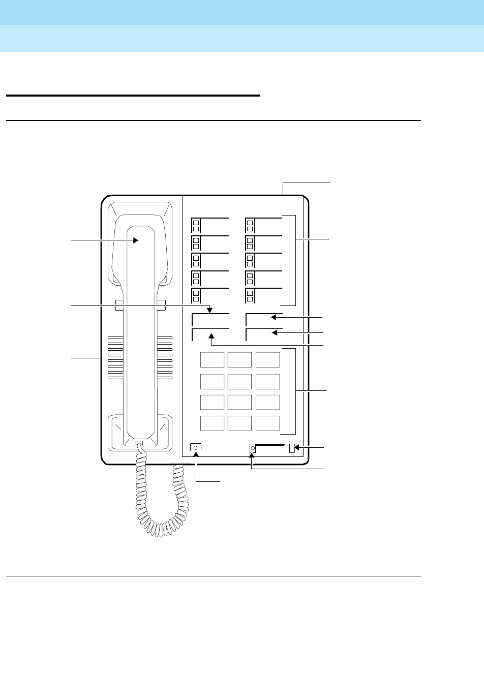
DEFINITYEnterpriseCommunicationsServerandSystem75andSystem85
Terminals and Adjuncts Reference
555-015-201 Issue 11
December 1999
The 7400 Series Voice Terminals
11-88The 7410D and 7410 Plus Voice Terminals
11
The 7410D and 7410 Plus Voice
Terminals
Figure 11-26. The 7410D (7401D01A) Voice Terminal
Message Select
Dial Pad
Handset
Transfer Button
Message Light
Ringer
Select Ring Light
Select Ring Button
123
456
789
ABC DEF
MNOJKLGHI
PRS TUV WXY
*
O#
Oper
7410D
Conference
Drop
Transfer
Hold
Conference
Button
Hold Button
10 Call Appearance/
Feature Buttons
Drop Button
Speakerphone/
Headset Adapter Jac
k
voice terminal)
(on side of
Volume Control
(on back of
voice terminal)
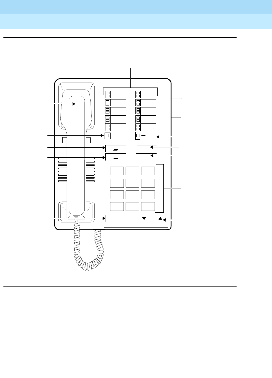
DEFINITYEnterpriseCommunicationsServerandSystem75andSystem85
Terminals and Adjuncts Reference
555-015-201 Issue 11
December 1999
The 7400 Series Voice Terminals
11-89The 7410D and 7410 Plus Voice Terminals
11
Figure 11-27. The 7410 Plus (7410D02A) Voice Terminal
Dial Pad
Handset
Transfer Button
Message Light
Drop/Test Button
Volume
123
456
789
ABC DEF
MNOJKLGHI
PRS TUV WXY
*
O#
Oper
7410 Plus
Speaker Button
Conference
Drop
Transfer
Hold
Conference/Ring
Button Hold Button
10 Call Appearance/
Feature Buttons
Speaker Volume
Ring
Test
Message Select
Select Button
Line Jack
Speakerphone/
Headset Adapter Jack
(on back of
voice terminal)
(on back of
voice terminal)
Control
Button
DEFINITYEnterpriseCommunicationsServerandSystem75andSystem85
Terminals and Adjuncts Reference
555-015-201 Issue 11
December 1999
The 7400 Series Voice Terminals
11-90The 7410D and 7410 Plus Voice Terminals
11
The 7410D (7410D01A) and 7410 Plus (7410D02A, the newest 7410 set) are
both multi-appearance digital voice terminals with 10 line appearances, four
standard fixed feature buttons and a Select Ring button. The 7410D and 7410
Plus voice terminals also provide a Message light, Ringer Volume control, a
Speakerphone/headset adapter jack on the back of the voice terminal for
connecting adjunct equipment, and, with the Select Ring feature, there are eight
possible programmable ringing patterns. A Self-Test feature can be activated to
test the lights and tone ringer on the voice terminal. In addition, the 7410 Plus
(7410D02A) provides a Speaker feature for listening-only functions.
NOTE:
The 7401D01A is no longer being manufactured.
Applications
The 7410D (7410D01A) and 7410 Plus (7410D02A) voice terminals can be used
with the DEFINITY Communications System Generic 1, Generic 2, and Generic 3,
the DEFINITY ECS, System 75, and System 85. These voice terminals are
especially suitable for managers, executive secretaries, and other office support
personnel who require access to multiple lines for call handling, call coverage,
bridging, conferencing, and sophisticated voice communications.
The 7410D and 7410 Plus voice terminals can also provide simultaneous voice
and data communications with the 7400B Data Module. PC platform products can
also be useful in providing voice capabilities since these screen-based products
can greatly enhance the telephone capabilities of these basic voice terminals.
Physical Description
Dimensions
NOTE:
The following dimensions for the 7410D and 7410 Plus voice terminals are
approximate.
Width = 6-3/8 inches
Depth (front to back) = 8-3/4 inches
Height (maximum with handset in place) = 5-1/2 inches
Thickness of housing = 1-1/2 inches

DEFINITYEnterpriseCommunicationsServerandSystem75andSystem85
Terminals and Adjuncts Reference
555-015-201 Issue 11
December 1999
The 7400 Series Voice Terminals
11-91The 7410D and 7410 Plus Voice Terminals
11
Features
Four Standard Fixed Feature Buttons
■CONFERENCE or CONFERENCE/RING button
■DROP or DROP/TEST button
■TRANSFER button
■HOLD button
Message Light
The Message light goes on when a message is left for the user. It goes off when
the user retrieves the message. On the 7410D voice terminal, the Message light is
green; on the 7410 Plus voice terminal, the Message light is red.
SELECT RING button (on 7410D)
On the 7410D (7410D01A) voice terminal has a SELECT RING button, which the
user can press along with the * key on the dial pad to select one of eight
personalized ringing patterns. The SELECT RING button along with the DROP
button is also used to perform a self-test of the lights and tone ringer on the voice
terminal. The SELECT RING button has a green status light associated with it.
SELECT button (on 7410 Plus)
The 7410 Plus (7410D02A) voice terminal has a SELECT button which can be
used in two ways:
■When used with the CONFERENCE/RING button, the user can select a
personalized ring from eight ringing patterns.
■When used with the DROP/TEST button, the user can initiate a self-test of
the lights and ringer on the voice terminal.
Call Appearance/Feature Buttons
The 7410D and 7410 Plus voice terminals have 10 call appearance/feature
buttons. Each of these buttons has a red in-use light and a green status light.
SPEAKER button (on 7410 Plus)
The 7410 Plus (7410D02A) voice terminal has a SPEAKER button which allows
the user to place calls while on-hook, to monitor calls on which the user has been
put on hold, or retrieve messages without lifting the handset. However, the
Speaker feature is for listening only. In order to speak to the other party, the user
must use the handset (the speaker must be off).

DEFINITYEnterpriseCommunicationsServerandSystem75andSystem85
Terminals and Adjuncts Reference
555-015-201 Issue 11
December 1999
The 7400 Series Voice Terminals
11-92The 7410D and 7410 Plus Voice Terminals
11
VOLUME control button (on 7410 Plus)
When the speaker is active on the 7410 Plus voice terminal speaker, the VOLUME
control button affects the loudness of the Speaker (listen-only) feature.
At all other times (when the speaker is not being used), the VOLUME control
button affects the volume of the tone ringer.
Other Physical Features
Handset
The 7410D and the 7410 Plus voice terminals are equipped with an R-type
handset.
Dial pad
The 7410D and 7410 Plus voice terminals are equipped with a 12-button
touch-tone dial pad. On the 7410 Plus voice terminal the letters “Q” and “Z” have
been added to the appropriate dial pad keys for directory access, and the “5”
button on the dial pad has raised bars for visually-impaired users.
Jacks
The 7410D and 7410 Plus voice terminals’ housing contains three jacks. On the
7410D voice terminal, the Handset cord jack is located on the front of the housing;
on the 7410 Plus voice terminal, this jack is on the back of the housing near the
front. The Line jack and the Speakerphone/headset adapter jack on both voice
terminals are on the back of the voice terminal.
Cords
Two cords are supplied with the 7410D (7410D01A) and the 7410 Plus
(7410D02A) voice terminal: a coiled 9-foot modular handset cord and a 7-foot
D8W 8-conductor modular line cord.
Optional longer cords are available: a 12-foot handset cord, 14-foot and 25-foot
line cords.
Ringing
The 7401D and 7401 Plus voice terminals have electronic tone ringing. With the
Personalized Ringing feature, the user can choose any one of eight different
ringing patterns.
The volume control on the 7410D (7410D01A) voice terminal is on the left side of
the housing.
The volume on the 7410 Plus (7410D02A) voice terminal can be controlled with
the VOLUME “arrow” button on the front of the voice terminal.

DEFINITYEnterpriseCommunicationsServerandSystem75andSystem85
Terminals and Adjuncts Reference
555-015-201 Issue 11
December 1999
The 7400 Series Voice Terminals
11-93The 7410D and 7410 Plus Voice Terminals
11
Mounting Options
The 7410D and 7410 Plus voice terminals comes equipped with a desk stand or
can be wall-mounted.
Color Options
The 7410D and 7410 Plus voice terminals are available in black and misty cream.
Distance Limitations
The maximum allowable distances of a 7410D or a 7410 Plus voice terminal from
the DEFINITY G1, G2, and G3, DEFINITY ECS, System 75, or System 85 cabinet
are shown in the following table.
Note:
These ranges can be extended to 5,000 feet (1524 m) for 24 AWG wire and 4,000 feet
(1219 m) for 26 AWG wire with the use of a Data Link Protector. Refer to the Exposed Port
Protection section earlier in this manual.
Power Requirements
The 7410D and 7410 Plus voice terminals receive power from the system and do
not require any external power supply. Additional external power is required when
the 7410D and 7410 Plus voice terminals are equipped with any adjuncts, such as
an external speakerphone. Refer to the Adjunct Power section earlier in this
manual.
Table 11-15. Distance Limitations for the 7410D and 7410 Plus Voice Terminals
System Port Board
Nominal Maximum Range in Feet
(Meters) (See Note)
24 AWG 26 AWG
System 85 SN270B
TN754
3,400 (1,034)
3,400 (1,034)
2,200 (671)
2,200 (671)
DEFINITY G2 SN270B
TN754
3,400 (1,034)
3,400 (1,034)
2,200 (671)
2,200 (671)
DEFINITY G1 and
G3, DEFINITY
ECS, and System
75
TN754 3,400 (1,034) 2,200 (671)
DEFINITYEnterpriseCommunicationsServerandSystem75andSystem85
Terminals and Adjuncts Reference
555-015-201 Issue 11
December 1999
The 7400 Series Voice Terminals
11-94The 7410D and 7410 Plus Voice Terminals
11
Switch Administration
Aliasing
The 7410 voice terminals must be aliased in the following way:
Button Numbering
The following button diagrams of the 7410D and 7410 Plus voice terminals will
help you administer both of these voice terminals connected to a System 75, a
DEFINITY G1 and G3, or DEFINITY ECS, and to a System 85 or a DEFINITY G2.
In these figures, the button numbers on the 10 administrable call appearance and
feature buttons (on both the 7410D and the 7410 Plus voice terminals)
correspond to button assignments on Page 2 of the voice terminal administration
screen form.
Figures 11-28 and 11-29 show button numbering for the 7410D (7410D01A) voice
terminal; Figures 11-30 and 11-31 show button numbering for the 7410 Plus
(7410D02A) voice terminal.
If you need more information, refer to
DEFINITY Communications System
Generic 3 Implementation
, 555-230-653, and
DEFINITY Communications System
Generic 2 Administration of Features and Hardware
, 555-104-507.
Table 11-16. Administering the 7410D and 7410 Plus Voice Terminals
If you are administering this
system:
For this type of voice
terminal:
The voice terminal must
be administered as:
System 75, R1V1, V2, V3,
System 85, R2V1, V2, V3, V4
and DEFINITY G1 and G3, and
DEFINITY ECS
7410D 7410 Plus a 7403D voice terminal
DEFINITY G2 7410D itself
DEFINITY G2 7410 Plus a 7410D voice terminal
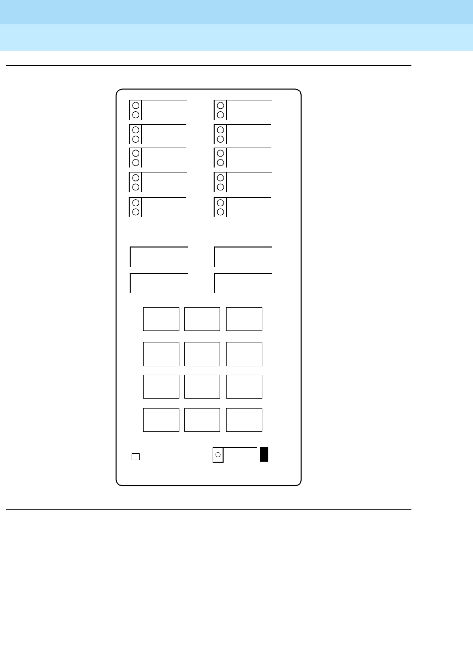
DEFINITYEnterpriseCommunicationsServerandSystem75andSystem85
Terminals and Adjuncts Reference
555-015-201 Issue 11
December 1999
The 7400 Series Voice Terminals
11-95The 7410D and 7410 Plus Voice Terminals
11
Figure 11-28. Button Numbering for Administering the 7410D Voice Terminal Connected
to a System 75, a DEFINITY G1 or G3, or a DEFINITY ECS
Conference
Drop
Transfer
Hold
Message
3
1
2
123
456
789
ABC DEF
MNOJKLGHI
PRS TUV WXY
*O#
Oper
4
5
8
6
7
9
10
Select
Ring
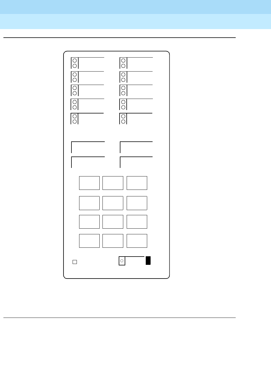
DEFINITYEnterpriseCommunicationsServerandSystem75andSystem85
Terminals and Adjuncts Reference
555-015-201 Issue 11
December 1999
The 7400 Series Voice Terminals
11-96The 7410D and 7410 Plus Voice Terminals
11
Figure 11-29. Button Numbering for Administering the 7410D Voice Terminal Connected
to a System 85 or a DEFINITY G2
Conference
Drop
Transfer
Hold
Message
5
3
4
123
456
789
ABC DEF
MNOJKLGHI
PRS TUV WXY
*O#
Oper
6
7
10
8
9
11
12
Select
Ring
NOTE: The Hold Button is Button #1.
The Message Light is Button #2.
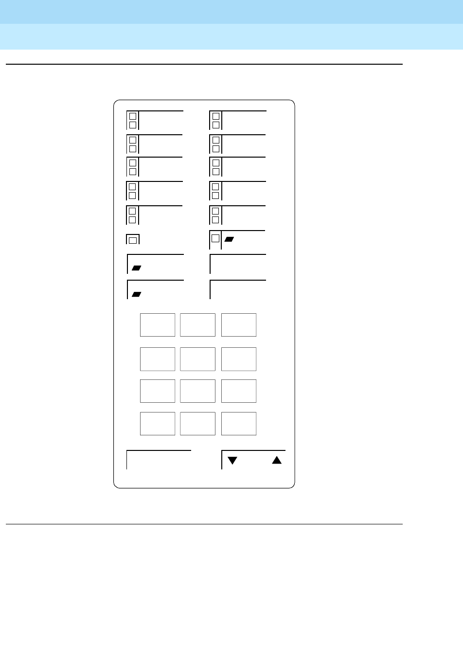
DEFINITYEnterpriseCommunicationsServerandSystem75andSystem85
Terminals and Adjuncts Reference
555-015-201 Issue 11
December 1999
The 7400 Series Voice Terminals
11-97The 7410D and 7410 Plus Voice Terminals
11
Figure 11-30. Button Numbering for Administering the 7410 Plus Voice Terminal
Connected to a System 75, a DEFINITY G1 or G3, or a DEFINITY ECS
Conference
Drop
Transfer
Hold
Speaker Volume
Ring
Test
Message Select
3
1
2
123
456
789
ABC DEF
MNOJKLGHI
PQRS TUV WXYZ
*O#
Oper
4
5
8
6
7
9
10
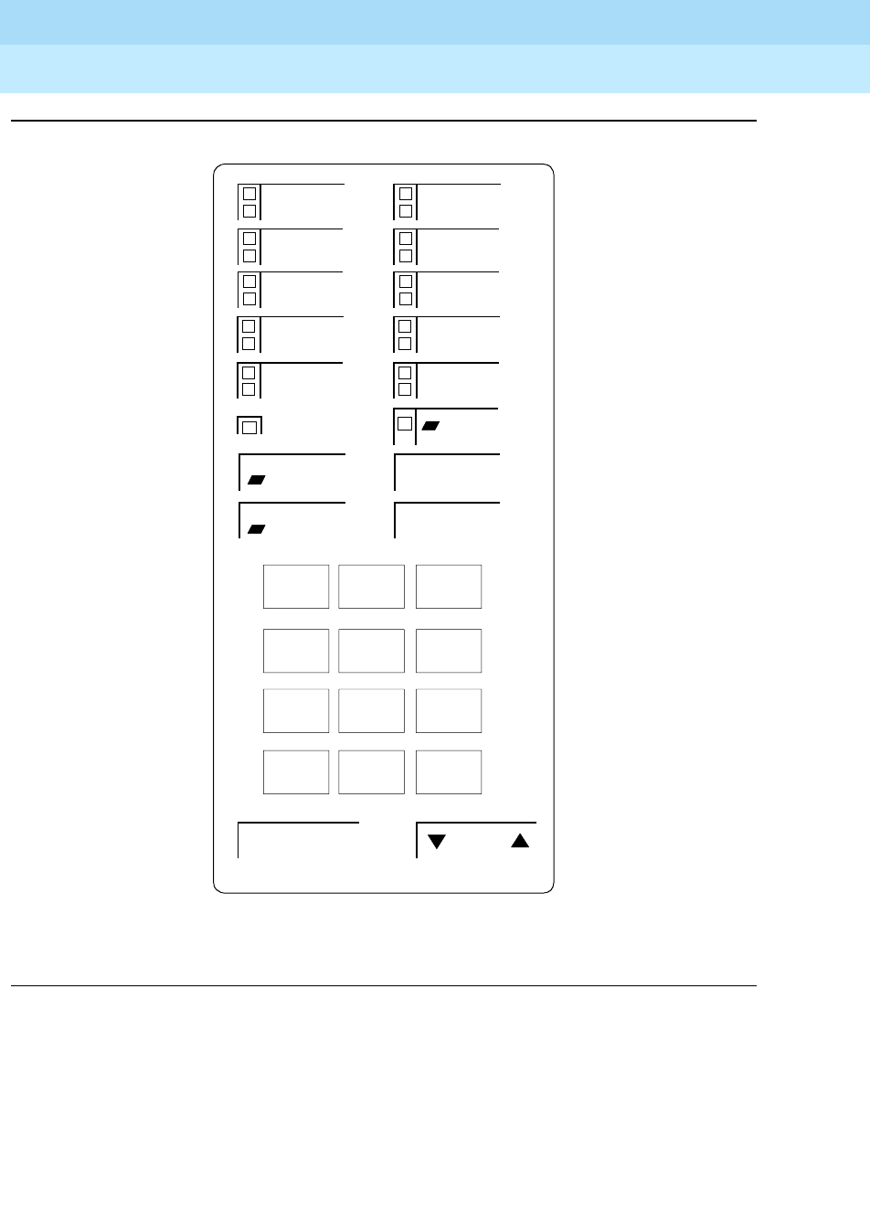
DEFINITYEnterpriseCommunicationsServerandSystem75andSystem85
Terminals and Adjuncts Reference
555-015-201 Issue 11
December 1999
The 7400 Series Voice Terminals
11-98The 7410D and 7410 Plus Voice Terminals
11
Figure 11-31. Button Numbering for Administering the 7410 Plus Voice Terminal
Connected to a System 85 or a DEFINITY G2
Conference
Drop
Transfer
Hold
Speaker Volume
Ring
Test
Message Select
NOTE: The Hold Button is Button #1.
5
3
4
123
456
789
ABC DEF
MNOJKLGHI
PQRS TUV WXYZ
*O#
Oper
6
7
10
8
9
11
12
The Message Light is Button #2.

DEFINITYEnterpriseCommunicationsServerandSystem75andSystem85
Terminals and Adjuncts Reference
555-015-201 Issue 11
December 1999
The 7400 Series Voice Terminals
11-99The 7410D and 7410 Plus Voice Terminals
11
Power Failure Operation
The 7410D and 7410 Plus voice terminals cannot be used as an emergency
station during power failure transfer conditions.
FCC Registration
These voice terminals are FCC-registered along with the switch (as a system), but
do not have a separate FCC registration label.
UL and CSA Approval
These voice terminals have been tested and have met the Underwriters
Laboratories (UL) Standards UL 1459 and have also met the Canadian Standards
Association (CSA) Standards CSA-C22.2 No.225-M90.
Hearing Aid Compatible
These voice terminals are compatible with the inductively coupled hearing aids
prescribed by the FCC.
7410D Equipment with PECs and Comcodes
The 7410D (7410D01A) voice terminal and components can be ordered with the
following PECs and Comcodes:
■Basic 7410D Voice Terminal
PEC: 3186-15D (Black=COL09; Misty Cream=COL22)
Comcode: Black=105418636; Misty Cream=105418677
■Handset
Comcode: Black=105157291; Misty Cream=105158885
■Handset cord (9 feet)
Comcode: Black=102803327; Misty Cream=104211305
■Handset cord (12 feet, black)
PEC: 2725-01L (Black=COL09; Misty Cream=COL22)
Comcode: Black=102401445; Misty Cream=104211339
■Line cord (9 feet)
Comcode: 103786778
■Line cord (14 feet, silver)
PEC: 2725-07N (COL18)
Comcode: 103786802
■Line cord (25 feet, silver)
PEC: 2725-07S (COL18)
Comcode: 103786828

DEFINITYEnterpriseCommunicationsServerandSystem75andSystem85
Terminals and Adjuncts Reference
555-015-201 Issue 11
December 1999
The 7400 Series Voice Terminals
11-100The 7410D and 7410 Plus Voice Terminals
11
■Graphic panel
Comcode: Black=846118016; Misty Cream=846118024
■Button designation card
(Package of 50)
PEC: 31861
Comcode: 846131977
■Desk stand/Wall mount assembly
Comcode: 846028546
7410 Plus Equipment PECs and Comcodes
The 7410 Plus (7410D02A) voice terminal and components can be ordered with
the following PECs and Comcodes:
■Basic 7410D02A Voice Terminal
PEC: 3186-PLS (Black=COL09; Misty Cream=COL22)
Comcode: Black=106224470; Misty Cream=106224488
■Handset
Comcode: Black=105519086; Misty Cream=105520787
■Handset cord (9 feet)
Comcode: Black=105635429; Misty Cream=105635437
■Handset cord (12 feet)
PEC: 2725-01L (Black=COL09; Misty Cream=COL22)
Comcode: Black=102401445; Misty Cream=104211339
■Line Cord (7 feet, silver)
Comcode: 103786778
■Line cord (14 feet, silver)
PEC: 2725-07N (COL18)
Comcode: 103786802
■Line cord (25 feet, silver)
PEC: 2725-07S (COL18)
Comcode: 103786828
■Button designation card
PEC: 31866 (Package of 50 cards)
Single sheets Comcode: 846523892
Pack of 50 Comcode: 846523900
Tractor feed, 200 Sheets Comcode: 846551448
Tractor feed, 500 Sheets Comcode: 846551455
■Faceplate
(Package of 50)
PEC: 31864 (Black=COL09; Misty Cream=COL22)
Comcode: Black=846551414, Misty Cream=846585677
■Desk stand/Wall mount assembly
Comcode: 846028546

DEFINITYEnterpriseCommunicationsServerandSystem75andSystem85
Terminals and Adjuncts Reference
555-015-201 Issue 11
December 1999
The 7400 Series Voice Terminals
11-101The 7410D and 7410 Plus Voice Terminals
11
Adjuncts
The following adjuncts can be used with this voice terminal:
■S101A Speakerphone (no longer orderable)
■S201A Speakerphone
■CS201A Speakerphone
■7400B Data Module
■500A Headset Adapter (and a standard headset: see “Headsets” below)
■R6 Amplifier Handset (PEC: 3152-002)
■R8 Noisy Location Handset (PEC: 3152-003)
■R2H Standard Handset (PEC: 3152-019)
■Shoulder Rest
Headsets
A list of compatible headsets, consisting of both modular and plug prong base
units and selection of headpieces, appears in “Headset Adapters” in the Adjuncts
section later in this manual.
Additional Documents
The following documents contain additional information relating to the 7410D and
7410 Plus voice terminals: (Use the 9-digit number listed after each document to
order the book from the BCS Publications Center for Lucent Technologies.)
■
7410D Voice Terminal Installation Instructions
, 555-015-102
■
System 75 7410D Voice Terminal User’s Guide
, 555-200-732
■
DEFINITY Communications System Generic 1 7410D Voice Terminal
User’s Guide
, 555-204-727
■
DEFINITY Communications System Generic 2 and System 85 7410D
Voice Terminal User’s Guide
, 555-104-716
■
DEFINITY Communications System Generic 1 and System 75 7410 Plus
Voice Terminal User’s Guide
, 555-204-743
■
DEFINITY Communications System Generic 2 and System 85 7410 Plus
Voice Terminal User’s Guide
, 555-104-743
The following document is shipped with every 7410 Plus voice terminal:
■
7401 Plus and 7410 Plus Voice Terminals Installation Instructions
,
555-015-128
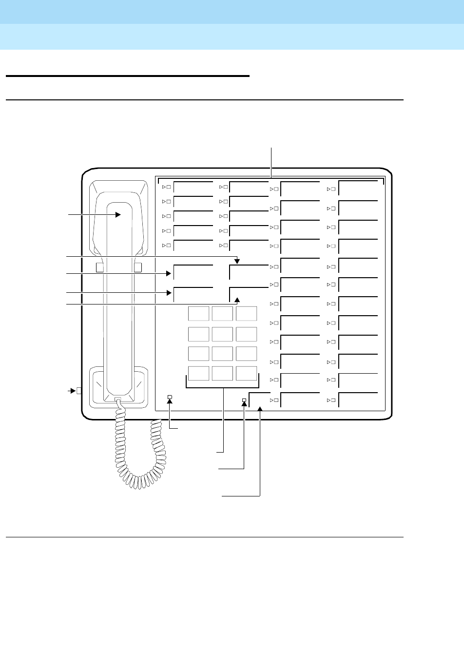
DEFINITYEnterpriseCommunicationsServerandSystem75andSystem85
Terminals and Adjuncts Reference
555-015-201 Issue 11
December 1999
The 7400 Series Voice Terminals
11-102The 7434D Voice Terminal
11
The 7434D Voice Terminal
Figure 11-32. The 7434D Voice Terminal
The 7434D is a multi-appearance digital voice terminal. It is an improved
descendant of the 7405D, which it resembles physically and functionally. The
7434D voice terminal has more call appearance capacity (DEFINITY G2 only)
than the 7405D and is lower in both cost and power consumption. It connects to a
digital line port in the system cabinet. The 7434D voice terminal supports an
adjunct display module or a call coverage module.
Handset
123
456
789
ABC DEF
MNOJKLGHI
PRS TUV WXY
*
O#
Oper
Conference
Drop
Transfer
Hold
34 Call Appearances/
Message
Select
Ring
Select
Ring Button
Dial Pad
Message
Select
Hold Button
Transfer
Conference
Drop Button
Volume
Control
(on left
Light
Ring Light
Button
Feature Buttons
side)
Button

DEFINITYEnterpriseCommunicationsServerandSystem75andSystem85
Terminals and Adjuncts Reference
555-015-201 Issue 11
December 1999
The 7400 Series Voice Terminals
11-103The 7434D Voice Terminal
11
Applications
The 7434D voice terminal can be used with the DEFINITY Communications
System Generic 1, Generic 2, and Generic 3, the DEFINITY ECS, System 75, or
System 85. It is an appropriate terminal for users who handle numerous calls and
who need button access to a wide variety of features. For example, the 7434D
voice terminal, with its large number of administrable buttons, can use the
Abbreviated Dialing feature for reaching many frequently called parties. The
buttons of the 7434D voice terminal can also be assigned for bridging calls at
other stations. Typical users are secretaries, managers, salespeople, buyers,
answering groups, and call covering positions. The 7434D can provide
simultaneous voice and data communications via the PC/PBX connection or
7400B Data Module.
Physical Description
Dimension
NOTE:
The following dimensions for the 7434D voice terminal are approximate.
Width = 10-1/2 inches
Depth (front to back) = 8-3/4 inches
Height (maximum with handset in place) = 6-1/2 inches
Thickness of housing = 1-1/2 inches
Features
Standard Fixed Feature Buttons
■CONFERENCE button
■TRANSFER button
■DROP button
■HOLD button
NOTE:
The DISCONNECT and RECALL buttons found on some earlier 7400
Series voice terminals have been removed from the 7434D voice terminal. A
RECALL button can be assigned on an administrable button if needed.

DEFINITYEnterpriseCommunicationsServerandSystem75andSystem85
Terminals and Adjuncts Reference
555-015-201 Issue 11
December 1999
The 7400 Series Voice Terminals
11-104The 7434D Voice Terminal
11
■SELECT RING button — a special fixed feature button that has two
functions:
— When used with the * dial pad key, it allows the user to select one of
eight personalized ringing patterns for incoming calls.
— When used with the DROP button, it allows the user to test the
lights, ringer, and display module (if installed) of the voice terminal.
The Select Ring test function replaces the Self-Test switch found on
most other terminals.
NOTE:
The associated Select Ring light goes on steadily when the button is
pressed to activate either function. It winks when the user is stepping
through the ringing patterns.
Administrable Buttons
The 7434D voice terminal has 34 call appearance/feature buttons (R2V1 and
R2V2 only), each equipped with a triangular red light and a square green status
light. Usually, at least three of these buttons (the top three in the leftmost column)
are administered as call appearances for the terminal’s primary extension
number, where calls are placed and answered. The rest of the buttons can be
used for more call appearances (including bridged appearances of other stations’
extensions) and features. Buttons administered for features have only their status
lights active.
Message light
The green light goes on when a message is left for the terminal user. It goes off
when the user retrieves the message.
Other Physical Features
Handset
The 7434D voice terminal is equipped with an R-type handset.
Dial pad
The 7434D voice terminal is equipped with a 12-button touch-tone dial pad.
Jacks
The 7434D voice terminal housing contains three jacks. The handset cord jack is
just under the left front edge of the housing. It is identified by a picture of a
handset molded into the plastic. The LINE jack and the OTHER jack (for adjunct
connections) are on the bottom center of the housing. The handset contains a
jack for the handset cord.
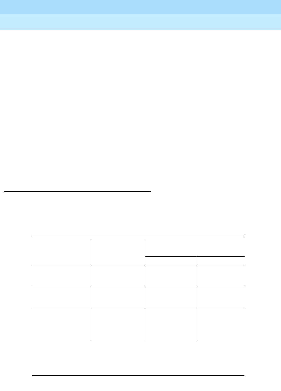
DEFINITYEnterpriseCommunicationsServerandSystem75andSystem85
Terminals and Adjuncts Reference
555-015-201 Issue 11
December 1999
The 7400 Series Voice Terminals
11-105The 7434D Voice Terminal
11
Cords
Two cords are supplied with the 7434D voice terminal: a coiled 7-foot modular
handset cord and a 7-foot modular line cord. Optional longer cords are available:
a 12-foot handset cord, 14-foot and 25-foot line cords.
Ringing
The 7434D voice terminal has electronic tone ringing with patterns that can be
selected via the SELECT RING button. The volume control is on the left side of
the housing.
Mounting Options
The 7434D voice terminal comes equipped with a nonadjustable desk stand. A
wall mounting kit can be ordered.
Color Options
The 7434D voice terminal is available in two colors: black with silver faceplate and
misty cream with gray faceplate.
Distance Limitations
The maximum allowable distances of a 7434D voice terminal from the DEFINITY
G1, G2, G3, DEFINITY ECS, System 75, or System 85 cabinet are shown in the
table below.
Note:
These ranges can be extended to 5,000 feet (1524 m) for 24 AWG wire and 4,000 feet
(1219 m) for 26 AWG wire with the use of a Data Link Protector. Refer to the Exposed Port
Protection section earlier in this manual.
Table 11-17. Distance Limitations for the 7434D Voice Terminal
System Port Board
Nominal Maximum Range in Feet
(Meters) (See Note)
24 AWG 26 AWG
System 85 SN270B
TN754
3,400 (1,034)
3,400 (1,034)
2,200 (671)
2,200 (671)
DEFINITY G2 SN270B
TN754
3,400 (1,034)
3,400 (1,034)
2,200 (671)
2,200 (671)
DEFINITY G1
and G3,
DEFINITY ECS,
and System 75
TN754 3,400 (1,034) 2,200 (671)

DEFINITYEnterpriseCommunicationsServerandSystem75andSystem85
Terminals and Adjuncts Reference
555-015-201 Issue 11
December 1999
The 7400 Series Voice Terminals
11-106The 7434D Voice Terminal
11
Power Requirements
The 7434D voice terminal is phantom-powered from the system cabinet, or from a
local power supply, on the digital pairs of the line wiring. Adjuncts connected to the
7434D voice terminal require auxiliary power and do not impose a drain on the
voice terminal supply. Refer to the Adjunct Power section earlier in this manual.
Power Failure Operation
The 7434D voice terminal cannot be used as an emergency station during power
failure transfer conditions.
FCC Registration
The 7434D voice terminal is not FCC registered.
Hearing Aid Compatible
This voice terminal is compatible with the inductively coupled hearing aids
prescribed by the FCC.
7434 Equipment PECs
The 7434D voice terminal and optional components were ordered with the
following PECs:
■Basic 7434D Voice Terminal (black) — 3187-39D MNT03
■Basic 7434D Voice Terminal (black) wall mounted — 3187-39D MNT13
■Basic voice terminal (misty cream) — 3187-39D MNT08
■Basic voice terminal (misty cream) wall mounted — 3187-39D MNT18
■Handset cord (12 feet, black) — 2725-01L COL09
■Handset cord (12 feet, misty cream) — 2725-01L COL20
■Line cord (14 feet, silver) — 2725-07N COL18
■Line cord (25 feet, silver) — 2725-07S COL18

DEFINITYEnterpriseCommunicationsServerandSystem75andSystem85
Terminals and Adjuncts Reference
555-015-201 Issue 11
December 1999
The 7400 Series Voice Terminals
11-107The 7434D Voice Terminal
11
Adjuncts
The following adjuncts can be used with the 7434D voice terminal:
■S101A Speakerphone
or
500A Headset Adapter
■S201A Speakerphone
or
500A Headset Adapter
■C401A or C401B Call Coverage Module
or
D401A or D401B Digital Display
Module
■7400B Data Module
NOTE:
Auxiliary power is required when any adjuncts are added to the basic voice
terminal.
Additional Documents
The following documents contain additional information relating to the 7434D
voice terminal:
■
7434D Voice Terminal Installation Guide
, 555-015-103
■
DEFINITY Generic 1 7434D Voice Terminal User’s Guide
, 555-204-733
■
System 75 7434D Voice Terminal User’s Guide,
555-200-733
■
DEFINITY Generic 2 and System 85 7434D Voice Terminal User’s Guide
,
555-104-709
■
DEFINITY Generic 1 and Generic 2, System 75, and System 85 Terminals
and Adjuncts Installation and Test
, 555-015-104
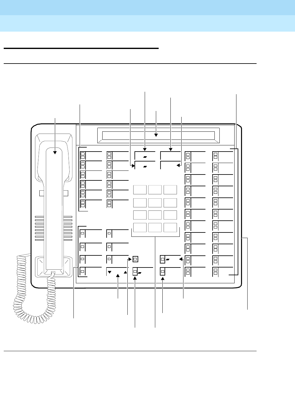
DEFINITYEnterpriseCommunicationsServerandSystem75andSystem85
Terminals and Adjuncts Reference
555-015-201 Issue 11
December 1999
The 7400 Series Voice Terminals
11-108The 7444 Voice Terminal
11
The 7444 Voice Terminal
Figure 11-33. The 7444 Voice Terminal
Volume
Handset
123
456
789
ABC DEF
MNOJKLGHI
PQRS TUV WXYZ
*
O#
Oper
Conference
Drop
Transfer
Hold
12 Call Appearance/
Control
Speaker
Select
Mute
Message
Mute Button
Select Button
Message Light
Dial Pad
Speaker/Reset
Spkr Button
22 Call Appearances/
Feature Buttons
Display
Transfer Button
Hold Button
Conference/Ring Button
Drop/Test Button
Volume Control
Button Speakerphone/
Headset Adapter
Jack (on back of
voice terminal)
Buttons
Ring
Test
Reset Spkr
7Display
Feature Buttons

DEFINITYEnterpriseCommunicationsServerandSystem75andSystem85
Terminals and Adjuncts Reference
555-015-201 Issue 11
December 1999
The 7400 Series Voice Terminals
11-109The 7444 Voice Terminal
11
The 7444 voice terminal is a multi-appearance digital voice terminal, similar to the
7434 voice terminal.The 7444 voice terminal is a multi-appearance digital voice
terminal, similar to the 7434 voice terminal. The 7444 offers 34 call
appearance/feature buttons, each with a red in-use light and a green status light,
four standard fixed feature buttons (CONFERENCE, DROP, HOLD, and
TRANSFER), three fixed feature buttons with one light each (SELECT,
SPEAKER/RESET SPKR, and MUTE), seven display feature buttons with one
light each, a Message light, personalized ringing, a built-in speakerphone with a
reset option, and a built-in 2-line by 40-character vacuum fluorescent display. Data
access can be provided by the addition of the PC/PBX Connection Card to any
AT&T compatible PC or by use of the 7400B Plus Data Module. This voice
terminal connects to a digital line port in the system cabinet and is powered from
the switch.
NOTE:
In order to use the display on the 7444 voice terminal, you must connect an
auxiliary power supply to the voice terminal. Recommended local power
supplies are the 1151A1 or 1151A2 with Battery Holdover or the MSP-1
Power Supply. For information about these power supplies, see the Adjunct
Power section earlier in this manual.
Applications
The 7444 voice terminal can be used with the DEFINITY Communications System
Generic 1, Generic 2, and Generic 3, the DEFINITYECS, System 75, or
System 85. It is an appropriate terminal for users who handle numerous calls and
who need button access to a wide variety of features. For example, the 7444 voice
terminal, with its large number of administrable buttons, can use the Abbreviated
Dialing feature for reaching many frequently called parties. The buttons of the
7444 voice terminal can also be assigned for bridging calls at other stations.
Typical users are secretaries, managers, salespeople, buyers, answering groups,
and call covering positions. The 7444 can provide simultaneous voice and data
communications via the PC/PBX connection or 7400B Plus Data Module.

DEFINITYEnterpriseCommunicationsServerandSystem75andSystem85
Terminals and Adjuncts Reference
555-015-201 Issue 11
December 1999
The 7400 Series Voice Terminals
11-110The 7444 Voice Terminal
11
Physical Description
Dimensions
NOTE:
The dimensions given here for the 7444 voice terminal are approximate.
Width = 12 inches
Depth (front to back) = 8-3/4 inches
Height (maximum with handset in place) = 6-1/4 inches
Thickness of housing = 1-1/2 inches
Features
Four Standard Fixed Feature Buttons
■CONFERENCE/RING button
■DROP/TEST button
■TRANSFER button
■HOLD button
SELECT button
The SELECT button can be used in three different ways: (The green light next to
the SELECT button goes on steadily when the SELECT button is activated.)
■Used with the CONFERENCE/RING button to select one of eight
personalized ringing patterns for incoming calls
■Used with the DROP/TEST button to initiate the Self-Test feature which
tests the lights, ringer, and display
■Used with the SPEAKER/RESET SPKR button to perform an acoustic test
of the environment and adjust the speakerphone to the surrounding
acoustic environment for optimal performance
Message light
The red Message light goes on when a message is left for the voice terminal user.
The light goes off when the user retrieves the message or when the message is
erased.
Call Appearance/Feature Buttons
The 7444D voice terminal has 34 call appearance/feature buttons, each equipped
with a red in-use and a green status light. Usually, at least three of these buttons
(the top three in the leftmost column) are administered as call appearances for the

DEFINITYEnterpriseCommunicationsServerandSystem75andSystem85
Terminals and Adjuncts Reference
555-015-201 Issue 11
December 1999
The 7400 Series Voice Terminals
11-111The 7444 Voice Terminal
11
terminal’s primary extension number, where calls are placed and answered. The
rest of the buttons can be used for more call appearances (including bridged
appearances of other stations’ extensions) and features. Buttons administered for
features have only their status lights active.
Seven Display Feature Buttons (with a green status light)
The 7444 has seven administrable display feature buttons, each with a green
status light. These buttons can be used for only display features, such as Inspect.
Speakerphone (Listen and Speak) Feature
The 7444 voice terminal is equipped with a built-in S201A-type speakerphone.
The Speakerphone capability allows a user to engage in a hands-free 2-way
conversation with the far-end party. The speakerphone can be turned off or on
with the SPEAKER/RESET SPKR button, can be muted with the MUTE button,
and the volume can be controlled with the VOLUME “arrow” button.
The SPEAKER/RESET SPKR button also allows the user to adjust the
speakerphone for optimal performance. By pressing the SELECT button and then
the SPEAKER/RESET SPKR button (if the voice terminal is set for the
Speakerphone feature), the user hears a set of tones as the speakerphone
performs an acoustic test of the environment. When the tones stop, the
speakerphone has finished adjusting itself and is ready for use. The user should
reset the speakerphone whenever the voice terminal is moved to another place
(even in the same room), whenever the green light next to the SPEAKER/RESET
SPKR button is fluttering, and in the unlikely event that the speakerphone is
making a squealing sound (in this last case, tones will not be heard during a call).
Speaker (Listen-only) Feature
The 7444 voice terminal can be optioned for the Speakerphone (listen and speak)
or
the Speaker (listen-only) feature. Use the SPEAKER/RESET SPKR button on
the front of the voice terminal for turning on and off the speaker or speakerphone.
The voice terminal is shipped with the Speakerphone setting in place, but, the
necessary DIP switch setting can be changed so that the voice terminal operates
with the Speaker feature instead. In this case, the S2 switch should be set to the
ON position, so that the voice terminal will operate with the Speaker (listen-only)
feature.
The Speaker (listen-only) capability allows a user to engage in a one-way
conversation with the far-end. Specifically, the user can only listen to the far-end;
the user is not able to transmit his voice over the speaker. To speak with the
far-end, the user must use the handset which turns off the speaker.
MUTE button
The MUTE button disables the transmitter of the speakerphone or the handset
depending on which is activated at that time. A red light next to the MUTE button
goes on when the Mute feature is activated.

DEFINITYEnterpriseCommunicationsServerandSystem75andSystem85
Terminals and Adjuncts Reference
555-015-201 Issue 11
December 1999
The 7400 Series Voice Terminals
11-112The 7444 Voice Terminal
11
VOLUME control button
The 7444 voice terminal has a VOLUME “arrow” button. This button has a double
function. When the user is on a call, the VOLUME button controls the volume of
the speaker or speakerphone, whichever is being used; when the user is not using
the speaker or speakerphone, the VOLUME control button adjusts the tone ringer.
When the user sets the volume for the speaker or speakerphone or for the tone
ringer, the display on the voice terminal shows a “bar array” that indicates the
volume setting.
Self-Test
By pressing the SELECT button and then the DROP/TEST button, the user can
initiate a test of the lights, ringer, and display on the voice terminal.
Display
The 7444 voice terminal is equipped with a built-in, 2-line, 40-character per line
vacuum fluorescent display.
Other Physical Features
Handset
The 7444 voice terminal is equipped with an R-type handset.
Dial pad
The 7444 voice terminal is equipped with a 12-button touch-tone dial pad. The
letters “Q” and “Z” have been added to the appropriate dial pad keys for directory
access, and the “5” button on your dial pad has raised bars for visually-impaired
users.
Jacks
The 7444 voice terminal housing contains a Line jack and Speakerphone/headset
adapter jack on the back of the voice terminal and a Handset cord jack just under
the left front edge of the housing.
Cords
Two cords are supplied with the 7444 voice terminal: a coiled 9-foot modular
handset cord and a 7-foot modular line cord.
Optional longer cords are available: a 12-foot handset cord, 14-foot and 25-foot
line cords.

DEFINITYEnterpriseCommunicationsServerandSystem75andSystem85
Terminals and Adjuncts Reference
555-015-201 Issue 11
December 1999
The 7400 Series Voice Terminals
11-113The 7444 Voice Terminal
11
Ringing
The 7444 voice terminal has electronic tone ringing with eight possible ringing
patterns that can be selected with the SELECT button and the
CONFERENCE/RING button. The loudness of the tone ringer can be controlled
by the VOLUME “arrow” button. (The user must not be on a speakerphone call. If
the user is using the speakerphone, the VOLUME “arrow” button controls the
volume of the speakerphone.)
Mounting Options
The 7444 voice terminal comes equipped with a nonadjustable desk stand. This
voice terminal cannot be wall-mounted.
Color Options
The 7444 voice terminal is available in black and misty cream.
Distance Limitations
The maximum allowable distances of a 7444 voice terminal from the
DEFINITY G1, G2, G3, DEFINITY ECS, System 75, or System 85 cabinet are
shown in the table below.
Note:
These ranges can be extended to 5,000 feet (1524 m) for 24 AWG wire and 4,000 feet
(1219 m) for 26 AWG wire with the use of a Data Link Protector. Refer to the Exposed Port
Protection section earlier in this manual.
Table 11-18. Distance Limitations for the 7444 Voice Terminal
System Port Board
Nominal Maximum Range in Feet
(Meters) (See Note)
24 AWG 26 AWG
System 85 SN270B
TN754
3,400 (1,034)
3,400 (1,034)
2,200 (671)
2,200 (671)
DEFINITY G2 SN270B
TN754
3,400 (1,034)
3,400 (1,034)
2,200 (671)
2,200 (671)
DEFINITY G1
and G3,
DEFINITY ECS,
and System 75
TN754 3,400 (1,034) 2,200 (671)

DEFINITYEnterpriseCommunicationsServerandSystem75andSystem85
Terminals and Adjuncts Reference
555-015-201 Issue 11
December 1999
The 7400 Series Voice Terminals
11-114The 7444 Voice Terminal
11
Power Requirements
The 7444 voice terminal is phantom-powered from the system cabinet on the
digital pairs of the line wiring.
In order to use the display on the 7444 voice terminal, you must connect an
auxiliary power source to the voice terminal. Recommended local power supplies
are the 1151A1 or 1151A2 with Battery Holdover or the MSP-1 Power Supply.
Switch Administration
Aliasing
The 7444 voice terminals must be aliased in the following way:
CAVEATS:
If the 7444 voice terminal is administered as a 7405D or a 7407D, the following
caveats apply:
Table 11-19. Administering the 7444 Voice Terminal
If you are administering
this system:
The 7444 voice terminal must be
administered as:
System 75, R1V1 a 7405D voice terminal (with display)
(See CAVEATS below)
System 75, R1V2 and R1V3 a 7405D voice terminal (with display)
or
a 7407D voice terminal
(See CAVEATS below)
System 85, R2V1 a 7405D voice terminal (with display)
(See CAVEATS below)
System 85, R2V2 through
R2V4 a 7405D voice terminal (with display)
or
a 7407D voice terminal
(See CAVEATS below)
DEFINITY G1 and G3, and
DEFINITY ECS a 7434 voice terminal (with display)
or
a 7407 voice terminal
(See CAVEATS below)
DEFINITY G2 a 7434 voice terminal (with display)
or
a 7407 voice terminal
(See CAVEATS below)

DEFINITYEnterpriseCommunicationsServerandSystem75andSystem85
Terminals and Adjuncts Reference
555-015-201 Issue 11
December 1999
The 7400 Series Voice Terminals
11-115The 7444 Voice Terminal
11
■Only 10 call appearance buttons can be administered with two lights, a red
and a green light.
■If the voice terminal is administered as a 7407D, the S1 switch on the back
of the 7444 voice terminal must be in the OFF position.
When the 7444 voice terminal is administered as a 7405D or a 7434 voice
terminal, the following caveats apply:
■The S1 switch on the back of the 7444 voice terminal must be in the ON
position.
■Only one line of the display will show switch-related information.
When a 7444 is administered as a 7434, the DEFINITY G1 and G3 and DEFINITY
ECS allows a maximum of 10 appearances of the primary line while the
DEFINITY G2 allows a maximum of 12 appearances. Each switch handles
appearances of other lines (that is, lines used in Bridging, Call Pickup, etc.) in a
different manner. Information about administering these appearances can be
found in switch documentation and help screens.
If there is a 7400B or 7400B Plus Data Module attached to the 7444 voice
terminal, the voice terminal must be administered with display
and
with data
module.
Button Numbering
The following button diagrams of the 7444 voice terminal will help you administer
it with a System 75, a DEFINITY G1 or G3, or DEFINITY ECS and with a System
85 and a DEFINITY G2. Figure 11-34 refers to the 7444 voice terminals
connected to a System 75, a DEFINITY G1 or G3, or DEFINITY ECS; Figure
11-35 refers to the 7444 voice terminal connected to a System 85 or a DEFINITY
G2.
If you need more information, refer to
DEFINITY Communications System
Generic 1 Implementation
, 555-230-653, and
DEFINITY Communications System
Generic 2 Administration of Features and Hardware
, 555-104-507.
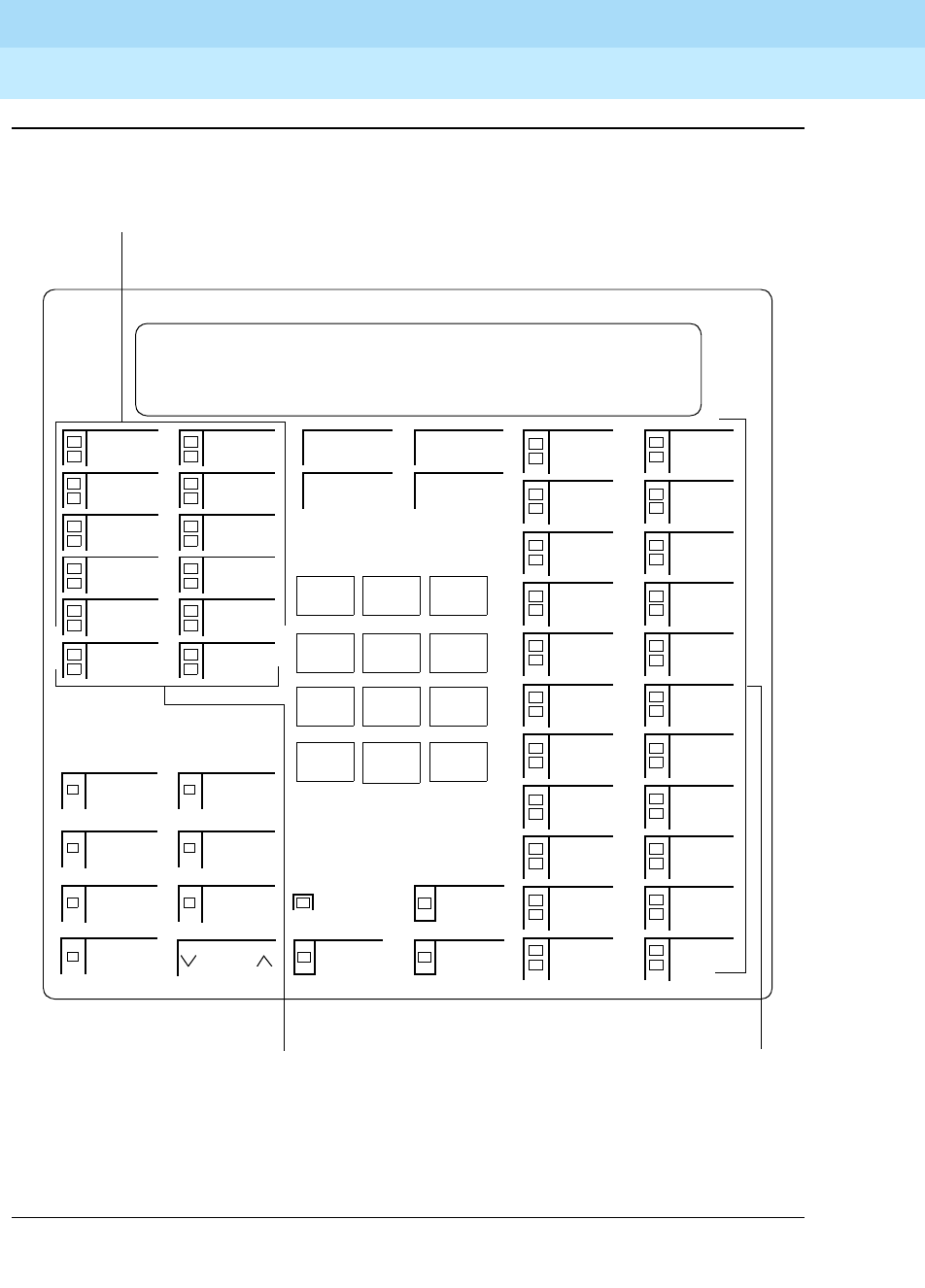
DEFINITYEnterpriseCommunicationsServerandSystem75andSystem85
Terminals and Adjuncts Reference
555-015-201 Issue 11
December 1999
The 7400 Series Voice Terminals
11-116The 7444 Voice Terminal
11
Figure 11-34. Button Numbering for Administering the 7444 Voice Terminal Connected
to a System 75, a DEFINITY G1 or G3, or a DEFINITY ECS
Volume
123
456
789
ABC DEF
MNOJKLGHI
PRS TUV WXY
*
O#
Oper
Conference
Drop
Transfer
Hold
Speaker
Select
Mute
Message
Feature Button
Ring
Test
Reset/Spkr
Assignments* 3 - 24
Feature Button
Assignments* 1 and 2
1
2
3
4
5
1
6
7
8
9
10
2
Display 1
Display 2
Display 3
Display 4
Display 5
Display 6
Display 7
* If aliased as a 7434, the feature button assignments are numbered 11 - 34
3
4
5
6
7
8
9
10
11
12
13
14
15
16
17
18
19
20
21
22
23
24
Button Assignments 1 - 10
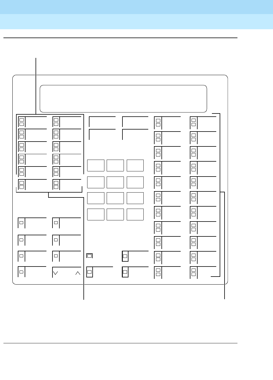
DEFINITYEnterpriseCommunicationsServerandSystem75andSystem85
Terminals and Adjuncts Reference
555-015-201 Issue 11
December 1999
The 7400 Series Voice Terminals
11-117The 7444 Voice Terminal
11
Figure 11-35. Button Numbering for Administering the 7444 Voice Terminal Connected
to a System 85 or a DEFINITY G2
Volume
123
45 6
789
ABC DEF
MNOJKLGHI
PQRS TUV WXYZ
*
O#
Oper
Conference
Drop
Transfer
Hold
Speaker
Select
Mute
Message
Feature Button
Ring
Test
Reset/Spkr
Assignments 15 - 36
Feature Button
Assignments 13 and 14
3
4
5
6
7
13
8
9
10
11
12
14
Display 1
Display 2
Display 3
Display 4
Display 5
Display 6
Display 7
NOTE: The Hold Button is Button #1.
15
16
17
18
19
20
21
22
23
24
25
26
27
28
29
30
31
32
33
34
35
36
Button Assignments 3 - 12
The Message Light is Button #2.

DEFINITYEnterpriseCommunicationsServerandSystem75andSystem85
Terminals and Adjuncts Reference
555-015-201 Issue 11
December 1999
The 7400 Series Voice Terminals
11-118The 7444 Voice Terminal
11
Power Failure Operation
The 7444 voice terminal cannot be used as an emergency station during power
failure transfer conditions.
FCC Registration
This voice terminal is FCC-registered along with the switch (as a system), but
does not have a separate FCC registration label.
UL and CSA Approval
This voice terminal has been tested and has met the Underwriters Laboratories
(UL) Standards UL 1459 and have also met the Canadian Standards Association
(CSA) Standards CSA-C22.2 No.225-M90.
Hearing Aid Compatible
This voice terminal is compatible with the inductively coupled hearing aids
prescribed by the FCC.
7444 Equipment PECs and Comcodes
The 7444D voice terminal and optional components can be ordered with the
following PECs and Comcodes:
■Basic 7444 Voice Terminal
PEC: 3187-VFD (Black=COL09; Misty Cream=COL22)
Comcode: Black=106200579; Misty Cream=106200587
■Handset
Comcode: Black=105519086; Misty Cream=105520787
■Handset cord (9 feet)
Comcode: Black=105635429; Misty Cream=105635437
■Handset cord (12 feet)
PEC: 2725-01L (Black=COL09; Misty Cream=COL22)
Comcode: Black=102401445; Misty Cream=104211339
■Line Cord (7 feet)
Comcode: 103786778
■Line cord (14 feet, silver)
PEC: 2725-07N COL18
Comcode: 103786802
■Line cord (25 feet, silver)
PEC: 2725-07S COL18
Comcode: 103786828

DEFINITYEnterpriseCommunicationsServerandSystem75andSystem85
Terminals and Adjuncts Reference
555-015-201 Issue 11
December 1999
The 7400 Series Voice Terminals
11-119The 7444 Voice Terminal
11
■Button designation card
PEC: 81005 (Package of 25)
Single, Comcode: Black=846604759; Misty Cream=846604767
Pack of 25 Sheets Comcode: Black=846692341;
Misty Cream=846692358
Tractor Feed, 200 Sheets Comcode: Black=846604775;
Misty Cream=846604783
Adjuncts
The following adjuncts can be used with the 7444 voice terminal:
NOTE:
Auxiliary power is required when any adjuncts are added to the basic voice
terminal, except for the 7400B Plus Data Module which is AC powered. An
MSP-1 Power Supply is recommended.
■S101A Speakerphone (no longer orderable)
■S201A Speakerphone
■CS201A Speakerphone
■7400B Plus Data Module
■500A Headset Adapter (and a standard headset; see “Headsets” below)
■Shoulder Rest
Headsets
A list of compatible headsets, consisting of both modular and plug prong base
units and selection of headpieces, appears in “Headset Adapters” in the Adjuncts
section later in this manual.
Additional Documents
The following documents contain additional information relating to the 7444 voice
terminal: (Use the 9-digit number listed after each document to order the book
from the BCS Publications Center for Lucent Technologies.)
■
DEFINITY Communications System Generic 1 and System 75 7444 Voice
Ter m in a l U se r’s Gu i de
, 555-204-744
■
DEFINITY Communications System Generic 2 and System 85 7444 Voice
Ter m in a l U se r’s Gu i de
, 555-104-744
The following instructions are shipped with every 7444 voice terminal:
■
7407 Plus and 7444 Voice Terminals Installation Instructions
, 555-015-129

DEFINITYEnterpriseCommunicationsServerandSystem75andSystem85
Terminals and Adjuncts Reference
555-015-201 Issue 11
December 1999
The 7400 Series Voice Terminals
11-120The 7444 Voice Terminal
11

The 8400 Series Voice Terminals
12-1
12
DEFINITYEnterpriseCommunicationsServerandSystem75andSystem85
Terminals and Adjuncts Reference
555-015-201 Issue 11
December 1999
12
The 8400 Series Voice Terminals
The following 8400 Series voice terminals are described in this section:
■8403 voice terminal
■8405 voice terminal
■8410 voice terminal
■8411 voice terminal
■8434 and 8434DX voice terminals
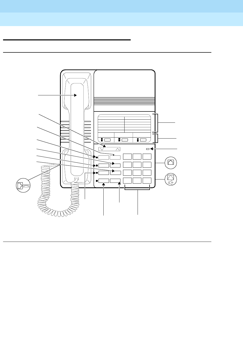
DEFINITYEnterpriseCommunicationsServerandSystem75andSystem85
Terminals and Adjuncts Reference
555-015-201 Issue 11
December 1999
The 8400 Series Voice Terminals
12-2The 8403 Voice Terminal
12
The 8403 Voice Terminal
Figure 12-1. One Version of the 8403 Voice Terminal
123
456
789
ABC DEF
MNOJKLGHI
PQRS TUV WXYZ
*
O#
8403
Transfer
Hold
ab c
Feature
Volume
Test Conf
Drop
LINE
Feature
3Call
Message
Line Jack
Speaker/
Dial Pad
Hold/Ring
Speaker
Mute
Handset Jack
Drop Button
Test Button
Conference
Feature
Transfer
Volume
Handset
Mute
Ring
Speaker
Message
Control
Button
Button
Button
Button
Button
Button
Button
Directory
Appearance
Buttons
Light
(on back of
terminal)
Headset
Adapter Jack
Jack (on back
of terminal
(on left side
of terminal)
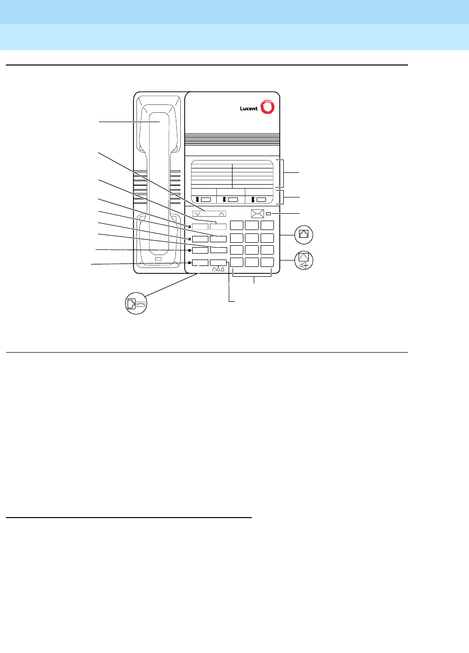
DEFINITYEnterpriseCommunicationsServerandSystem75andSystem85
Terminals and Adjuncts Reference
555-015-201 Issue 11
December 1999
The 8400 Series Voice Terminals
12-3The 8403 Voice Terminal
12
Figure 12-2. Another Version of the 8403 Voice Terminal
The 8403 voice terminal is a multi-appearance digital telephone with three call
appearance buttons, Conference, Transfer, Drop, and Hold buttons, a TEST
button, a blue FEATURE button which allows you to access 12 system features
assigned by the System Manager and to choose from among eight different
ringing patterns, a MUTE button, a SPEAKER button which accesses a 1-way,
listen-only speaker, a red Message light, and a Volume control button.
The 8403 can be used in either a 4-wire or 2-wire environment. For more
information, see the section on “Wiring Information.”
Applications
The 8403 voice terminal can be used with the DEFINITY Communications System
Generic 1, Generic 2, and Generic 3, the DEFINITY ECS, System 75, and
System 85. This voice terminal is especially suitable for general office workers
with low call volumes, manufacturing, warehousing, guard and/or reception areas,
or office desks.
The 8403 voice terminal can also provide simultaneous voice and data
communications with the 7400B Plus Data Module. PC platform products can also
be useful in providing voice capabilities since these screen-based products can
greatly enhance the telephone capabilities of these basic voice terminals.
123
456
789
ABC DEF
MNOJKLGHI
PQRS TUV WXYZ
*
O#
Transfer
Hold
ab c
Feature
Volume
Test Conf
Drop
LINE
Feature Directory
3 Call appearance buttons
Dial pad
Test button
Volume control button
Handset
Mute
Speaker
Message light
Line jack (on back of
voice terminal)
Speakerphone/
headset adapter
jack (on back of
voice terminal)
Hold/Ring
button
Handset jack
Drop button
Conference button
Feature button
Transfer button
Mute button
Speaker button

DEFINITYEnterpriseCommunicationsServerandSystem75andSystem85
Terminals and Adjuncts Reference
555-015-201 Issue 11
December 1999
The 8400 Series Voice Terminals
12-4The 8403 Voice Terminal
12
Physical Features
Dimensions
NOTE:
The dimensions described here for the 8403 voice terminal are approximate.
Width = 7-3/4 inches
Depth (front to back) = 9-7/16 inches
Height (maximum with handset in place) = 5-1/2 inches
Thickness of housing = 1-1/2 inches
Features
Eight Fixed Feature Buttons
The 8403 has the following eight fixed feature buttons:
■CONFERENCE button (labeled CONF)
■DROP button
■TRANSFER button
■A red HOLD button
■A blue FEATURE button
■MUTE button
■SPEAKER button
■TEST button
The Feature Button
The blue FEATURE button allows the dial pad to serve as 12 feature buttons
without indicators. These features are accessed by pressing the FEATURE button
and then one of the 12 dial pad keys. The Feature Directory on the faceplate on
the top of the telephone lists the features administered at F1 through F9,F*,F0,
and F#.
TheFEATUREbuttoncanalsobeusedwiththeHOLDbuttontoselectyourown
personalized ringing pattern from among eight available patterns.
Feature Directory
The 8403 voice terminal has a Feature Directory card, which has space for 12
features assigned by the System Manager. These features are labeled F1 through
F9,F*,F0, and F#.

DEFINITYEnterpriseCommunicationsServerandSystem75andSystem85
Terminals and Adjuncts Reference
555-015-201 Issue 11
December 1999
The 8400 Series Voice Terminals
12-5The 8403 Voice Terminal
12
Call Appearance Buttons
The 8403 voice terminal has three call appearance buttons. Each of the buttons
has a red light and a green status light.
Message Light
The red Message light goes on when a message is left for the user. It goes off
when the user retrieves the message or when the message is erased. This light is
labeled either
Message
or .
SPEAKER Button
The 8403 voice terminal is set for the 1-way, listen-only Speaker feature. The user
can only listen to the far-end. To speak with the other party, the user must use the
handset which turns off the speaker.
MUTE button
The MUTE button is a fixed feature button with a red status light. The MUTE
button turns off the microphone of the handset so that a person can converse with
another person in the room without the other party listening in.
VOLUME Control button
The 8403 voice terminal has a VOLUME “arrow” button on the front of the set.
This button has several functions. When the user is using the 1-way speaker, the
VOLUME button controls the volume of the speaker. When the user is on a call
using the handset, the VOLUME button controls the volume of the handset. When
the voice terminal is idle, the button controls the volume of the tone ringer.
TEST Button
When the voice terminal is initially powered up, the green light next to the TEST
button flashes if the link with the PBX is not (or not yet) operational. The light
changes to steady green when the voice terminal is able to communicate with the
PBX. After the voice terminal is powered up, you can press the TEST button to
test the lights on your voice terminal.
Other Physical Features
Handset
The 8403 voice terminal is equipped with a K-type handset.
Dial pad
The 8403 voice terminal is equipped with a 12-button touch-tone dial pad. The
letters “Q” and “Z” have been added to the appropriate dial pad keys for directory
access, and the “5” button on the dial pad has raised bars for visually-impaired
users.

DEFINITYEnterpriseCommunicationsServerandSystem75andSystem85
Terminals and Adjuncts Reference
555-015-201 Issue 11
December 1999
The 8400 Series Voice Terminals
12-6The 8403 Voice Terminal
12
Jacks
The 8403 voice terminal’s housing has a Line jack and a Handset cord jack
located on the back of the housing. There is also a Speakerphone/headset
adapter jack on the back of the set to which the user can connect adjunct
equipment.
Cords
Two cords are supplied with the 8403: a coiled 9-foot handset cord and a 7-foot
line cord.
Optional longer cords are available: a 12-foot handset cord and 14-foot and
25-foot line cords.
Ringing
The 8403 voice terminal has electronic tone ringing. With the Select Ring feature,
the user can choose any one of eight different ringing patterns. The set has a
Volume control button which controls the loudness of the ringer, the speaker, and
the handset.
Mounting Options
The 8403 voice terminal comes equipped with a nonadjustable desk stand.
However, the user may choose to remove the stand and then mount the voice
terminal on the wall.
Color Options
The 8403 voice terminal is available in black and in white.
Wiring Information
The 8403 voice terminal works in both 4-wire and 2-wire DCP configurations. The
table below describes the pins on an 8400-Series voice terminal LINE jack.
Table 12-1. The Pins on an 8400-Series Voice Terminal LINE Jack
Line Interface
Pin Pair Name Description
12 OD14-WireOutput
22 OD24-WireOutput
3 3 ID1 4-Wire Input
41 U-T 2-Wire(Tip)
5 1 U-R 2-Wire (Ring)
DEFINITYEnterpriseCommunicationsServerandSystem75andSystem85
Terminals and Adjuncts Reference
555-015-201 Issue 11
December 1999
The 8400 Series Voice Terminals
12-7The 8403 Voice Terminal
12
NOTE:
Regardless of which configuration is in use, ALL wiring between the PBX
and the terminal MUST consist of twisted-pairs, including the modular line
cord. The line cord must be a D8W, which consists of 4 twisted-pairs, or a
Lucent Technologies-approved equivalent.
Twisted-pair wiring is used to make lines less sensitive to crosstalk.
Therefore, failure to use twisted pair wiring may result in less-than-optimum
performance of the terminal and may also contribute to problems with the
line.
An 8-wire modular cord MUST be used for all 4-wire and any 2-wire
installations requiring auxiliary power.
NOTE:
You do NOT need to change any settings on the voice terminal for 2-wire or
4-wire installations. The voice terminal is able to detect whether it is in a
2-wire or a 4-wire configuration.
For 2-wire operation, if you need to plug the voice terminal into a 4-pin or
6-pin wall jack, instead of a standard 8-pin modular jack, refer to the “Line
Interface” table to insure that the wires from the 4-pin or 6-pin wall jack are
connected to the correct pins on the terminal “LINE” jack.
In order for the terminal to function properly in either 2-wire or 4-wire
installations, there must be NO INTERCONNECTIONS between the wire
pairs used for 2-wire and 4-wire operations. Bridging or paralleling of these
pairs can result in damage to the terminal or can cause the PBX circuit pack
to remove power to the terminal.
REMOVE ALL CONNECTIONS BETWEEN PAIRS BEFORE
CONNECTING THE TERMINAL.
4-WIRE installations MUST ONLY have PBX connections on pair 2 and pair
3 and, if necessary, auxiliary power must be connected to pair 4.
2-WIRE installations MUST ONLY have PBX connections on pair 1 and, if
necessary, auxiliary power must be connected to pair 4.
6 3 ID2 4-Wire Input
7 4 P1- Adjunct Power -48V
8 4 P2+ Adjunct Power Common
Table 12-1. The Pins on an 8400-Series Voice Terminal LINE Jack
Line Interface
Pin Pair Name Description
DEFINITYEnterpriseCommunicationsServerandSystem75andSystem85
Terminals and Adjuncts Reference
555-015-201 Issue 11
December 1999
The 8400 Series Voice Terminals
12-8The 8403 Voice Terminal
12
Distance Limitations
The following circuit packs can be used with all of the 8400-Series sets.
In 4-wire operation, the voice terminal must be within 5,000 feet of the PBX using
22-gauge or 24-gauge wire, and within 4,000 feet of the PBX using 26-gauge wire.
In 2-wire operation, the voice terminal must be within 5,500 feet of the PBX using
22-gauge wire, within 3,500 feet of the PBX using 24-gauge wire, and within 2,200
feet of the PBX using 26-gauge wire.
Power Requirements
The 8403 voice terminal receives power from the system and does not require any
external power supply. Additional external power IS required when the 8403 voice
terminal is equipped with any adjuncts, such as an external speakerphone. In this
instance, an 1151A1 local power supply or an 1151A2 power supply with Battery
Holdover is recommended. Refer to the Adjunct Power section earlier in this
manual for more information about these power supplies.
Table 12-2. Distance Limitations for the 8403 Voice Terminal
Circuit Pack 2/4-Wire Will support these switches
TN2181 - 16-port 2-wire G3V3, G3V2
TN754b - 8-port 4-wire All switches except System 85
TN754 - 8-port 4-wire All switches except System 85
TN413 - 8-port 4-wire International System 75
SN 270 and
SN270B - 4-port 4-wire System 85 R2V2 - R2V4
DEFINITYEnterpriseCommunicationsServerandSystem75andSystem85
Terminals and Adjuncts Reference
555-015-201 Issue 11
December 1999
The 8400 Series Voice Terminals
12-9The 8403 Voice Terminal
12
Switch Administration
Aliasing
Use the following table for administering the 8403 voice terminal:
Button Numbering
The following button diagrams of the 8403 voice terminal will help you administer
both of these voice terminals connected to a System 75, a DEFINITY G1 and G3,
or a DEFINITY ECS, and to a System 85 or a DEFINITY G2.
Figure 12-3 shows button numbering for the 8403 connected to a
System 75, DEFINITY G1 and G3, or a DEFINITY ECS. Figure 12-4 shows button
numbering for the 8403 connected to a System 85 or DEFINITY G2.
If you need more information, refer to
DEFINITY Communications System
Generic 3 Implementation
, 555-230-653, and
DEFINITY Communications System
Generic 2 Administration of Features and Hardware
, 555-104-507.
Table 12-3. Administering the 8403 Voice Terminal
If you have this System
and this
Release
(which can
support this
type of
operation)
Administer
the 8403 as a
System 75 R1V1 — R1V3 4-wire only 7405
System 85 R2V2 — R2V4 4-wire only 7405
International System 75 IR1V4, etc. 4-wire only 7405
DEFINITY G1 4-wire only 7405
Global DEFINITY’ 91 4-wire only 7405
DEFINITY G2V1 4-wire only 7405
DEFINITY G2V2 4-wire only 7405
DEFINITY G3i, G3r, G3s,
G3vs 4-wire only 7405
DEFINITY G3V2 2- or 4-wire 7405
DEFINITY G3V3 and
later 2- or 4-wire 8403
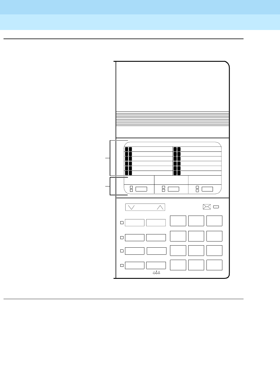
DEFINITYEnterpriseCommunicationsServerandSystem75andSystem85
Terminals and Adjuncts Reference
555-015-201 Issue 11
December 1999
The 8400 Series Voice Terminals
12-10The 8403 Voice Terminal
12
Figure 12-3. Button Numbering for Administering the 8403 Voice Terminal Connected to
a System 75, DEFINITY G1 or G3, or DEFINITY ECS
123
456
789
ABC DEF
MNOJKLGHI
PQRS TUV WXYZ
*
O#
8403
Transfer
Hold
ab c
Feature
Volume
Test Conf
Drop
Mute
Speaker
123
If administered as a 7405D,
F1 through F7 are administered
as “BUTTON ASSIGNMENTS”
4 through 10. F8, F9, F*, F0, and
F# are administered as “FEATURE
BUTTON ASSIGNMENTS”
1 through 5.
If administered as itself, administer
F1 through F9, F*, F0, and F# as
“FEATURE BUTTON ASSIGNMENTS”
1 through 12.
Call appearance buttons a, b, and c
are administered as call appearance
“BUTTON ASSIGNMENTS”
1, 2, and 3.
F1
F2
F3
F4
F5
F6
1
2
3
4
5
6
7
8
9
10
11
12
F7
F8
F9
F*
F0
F#
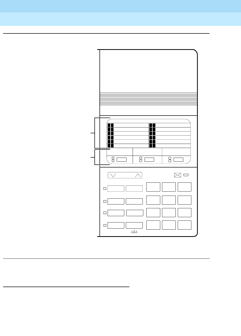
DEFINITYEnterpriseCommunicationsServerandSystem75andSystem85
Terminals and Adjuncts Reference
555-015-201 Issue 11
December 1999
The 8400 Series Voice Terminals
12-11The 8403 Voice Terminal
12
Figure 12-4. Button Numbering for Administering the 8403 Voice Terminal Connected to
a System 85 or a DEFINITY G2
Power Failure Operation
The 8403 voice terminal cannot be used as an emergency station during power
failure transfer conditions.
123
456
789
ABC DEF
MNOJKLGHI
PQRS TUV WXYZ
*
O#
8403
Transfer
Hold
ab c
Feature
Volume
Test Conf
Drop
Mute
Speaker
345
If administered as a 7405D,
F1 through F7 are administered
as “BUTTON ASSIGNMENTS”
6 through 12. F8, F9, F*, F0, and
F# are administered as “FEATURE
BUTTON ASSIGNMENTS”
13 through 17.
If administered as itself, administer
F1 through F9, F*, F0, and F# as
“FEATURE BUTTON ASSIGNMENTS”
1 through 12.
Call appearance buttons a, b, and c
are administered as call appearance
“BUTTON ASSIGNMENTS”
3, 4, and 5.
F1
F2
F3
F4
F5
F6
6
7
8
9
10
11
12
13
14
15
16
17
F7
F8
F9
F*
F0
F#

DEFINITYEnterpriseCommunicationsServerandSystem75andSystem85
Terminals and Adjuncts Reference
555-015-201 Issue 11
December 1999
The 8400 Series Voice Terminals
12-12The 8403 Voice Terminal
12
FCC Registration
The 8403 voice terminal is FCC-registered along with the switch (as a system),
but does not have a separate FCC registration label.
UL and CSA Approval
This voice terminal has been tested and has met the Underwriters Laboratories
(UL) Standards UL 1459 and has also met the Canadian Standards Association
(CSA) Standards CSA-C22.2 No.225-M90.
Hearing Aid Compatible
This voice terminal is compatible with the inductively coupled hearing aids
prescribed by the FCC.
8403 Equipment PECs and Comcodes
The 8403 (8403D01A) voice terminal and components can be ordered with these
PECs and Comcodes:
■Basic 8403 (8403D02A) Voice Terminal
Black 8403 Set PEC: 3233-03B
Comcode: 107702144;
White 8403 Set PEC: 3233-03W
Comcode: 107702177
■K2S8 Handset
Comcode: Black=107545584; White=107545568
■Handset cord (9 feet)
Comcode: Black=407632819; White=407632835
■Line cord (7 feet)
Comcode: 103786778
■Line cord (14 feet, silver)
PEC: 2725-07N (COL18)
Comcode: 103786828
■Line cord (25 feet, silver)
PEC: 2725-07S (COL18)
Comcode: 103786802
■Designation Card Cover
PEC: 32306
Comcode: 846506780

DEFINITYEnterpriseCommunicationsServerandSystem75andSystem85
Terminals and Adjuncts Reference
555-015-201 Issue 11
December 1999
The 8400 Series Voice Terminals
12-13The 8403 Voice Terminal
12
■Button Designation Cards
Tractor Feed For 25 Sets, 5 Sheets
PEC: 32307
Comcode: 847167962
Tractor Feed, For 100 Sets, 20 Sheets
PEC: 32308
Comcode: 847167970
Adjuncts
The following adjuncts can be used with the 8403 voice terminal:
■S101A Speakerphone (no longer orderable)
■S201A Speakerphone
■CS201A Speakerphone
■7400B Plus Data Module
■500A Headset Adapter (and a standard headset; see “Headsets” below)
■K6S2 Amplifier Handset
■Shoulder Rest
Headsets
A list of compatible headsets, consisting of both modular and plug prong base
units and selection of headpieces, appears in “Headset Adapters” in the Adjuncts
section later in this manual.
Additional Documents
The following documents contain additional information relating to the 8403 voice
terminal: (Use the 9 digit number listed after each document to order that book
from the BCS Publications Center for Lucent Technologies.)
■
8403, 8410, and 8434 Voice Terminals Instructions for Installation, Switch
Administration, and Programming the Options
, 555-015-164
■
DEFINITY Communications System Generic 1 and 3 and System 75 8403
Voice Terminal User’s Guide
, 555-230-761
■
DEFINITY Communications System Generic 1 and 3 and System 75 8403
Voice Terminal Quick Reference Guide
, 555-230-762
■
DEFINITY Communications System Generic 2 and System 85 8403 Voice
Ter m in a l U se r’s Gu i de
, 555-104-761
■
DEFINITY Communications System Generic 2 and System 85 8403 Voice
Terminal Quick Reference Guide
, 555-104-762
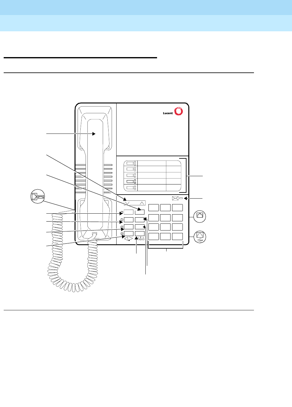
DEFINITYEnterpriseCommunicationsServerandSystem75andSystem85
Terminals and Adjuncts Reference
555-015-201 Issue 11
December 1999
The 8400 Series Voice Terminals
12-14The 8405B, 8405B Plus, 8405D, and 8405D Plus Voice Terminals
12
The 8405B, 8405B Plus, 8405D, and
8405D Plus Voice Terminals
Figure 12-5. One Version of the 8405B and 8405B Plus Voice Terminals
Volume
Shift Transfer
Test Conf
Mute Drop
Hold
123
456
789
ABC DEF
MNOJKLGHI
PQRS TUV WXYZ
*
O#
Dial Pad
Handset
Hold/Ring
Transfer
Shift
5Call
Message
Test Button
Mute Button
Speaker/
LINE
Line Jack
Speakerphone/
Volume
Button
Conference Button
(on back of
terminal)
Headset
Light
Appearance/
Feature
Buttons
Adapter Jack
(on back of
Control
Button
Button
Reset
Speaker
Button
Button
Handset
Jack (on
left side
of terminal)
Drop Button
terminal)
Speaker
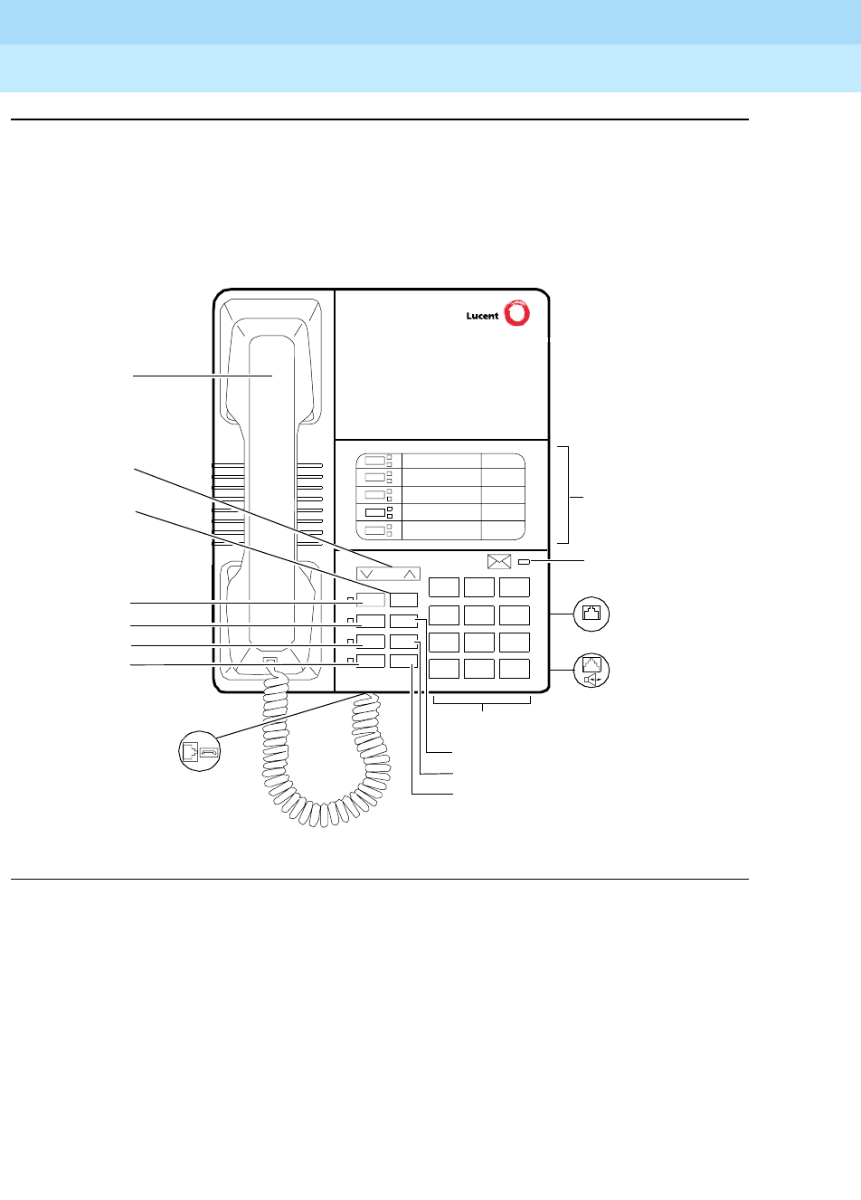
DEFINITYEnterpriseCommunicationsServerandSystem75andSystem85
Terminals and Adjuncts Reference
555-015-201 Issue 11
December 1999
The 8400 Series Voice Terminals
12-15The 8405B, 8405B Plus, 8405D, and 8405D Plus Voice Terminals
12
Figure 12-6. Another Version of the 8405B and 8405B Plus Voice Terminals
Volume
Ring Transfer
Test Conf
Mute Drop
Speaker Hold
123
456
789
ABC DEF
MNOJKLGHI
PQRS TUV WXYZ
*
O#
Dial pad
Handset
Hold button
Transfer
Conference button
Ring button
5 Call appearance/
feature buttons
Message light
Test button
Mute button
Speaker button
Handset jack
Line jack (on back
of voice terminal)
Speakerphone/
headset adapter
jack (on back of
voice terminal)
Drop button
Volume
LINE
button
control
button
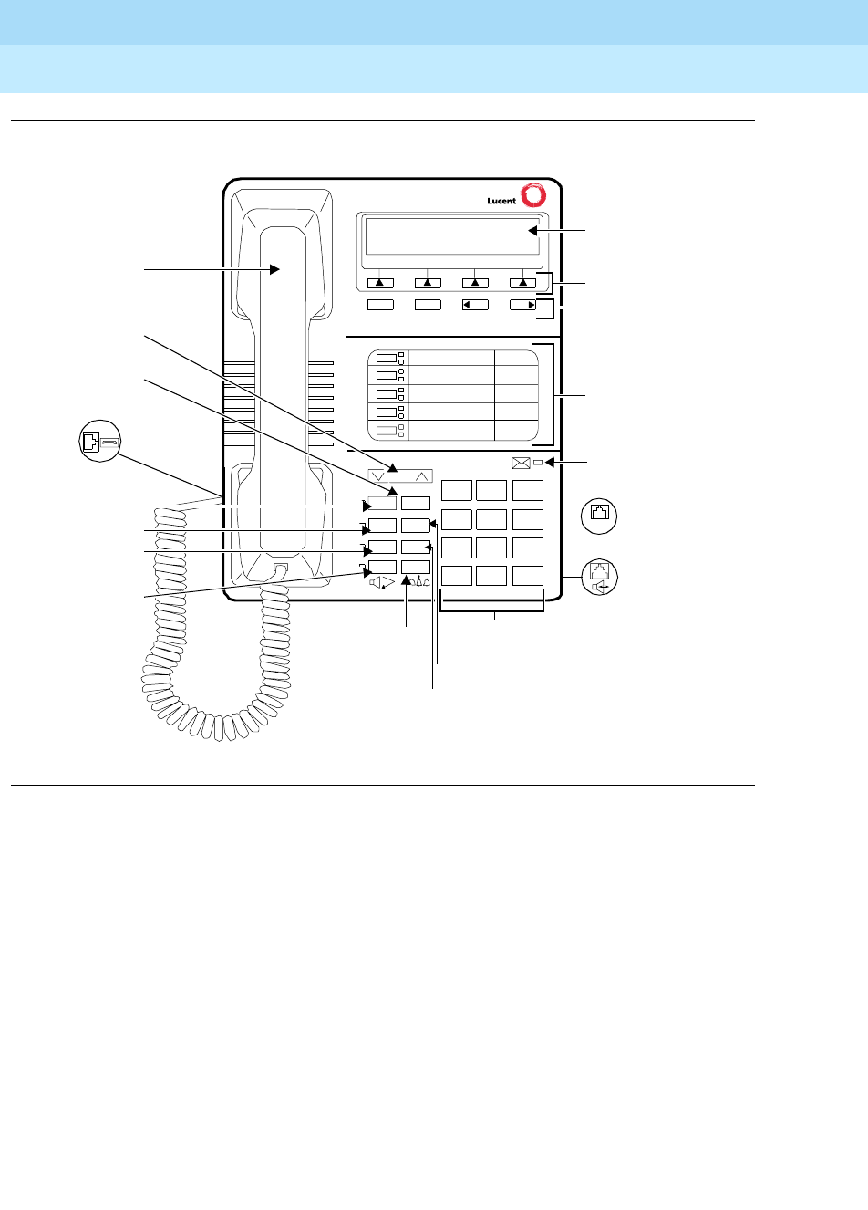
DEFINITYEnterpriseCommunicationsServerandSystem75andSystem85
Terminals and Adjuncts Reference
555-015-201 Issue 11
December 1999
The 8400 Series Voice Terminals
12-16The 8405B, 8405B Plus, 8405D, and 8405D Plus Voice Terminals
12
Figure 12-7. One Version of the 8405D and 8405D Plus Voice Terminal (With Display)
Volume
Shift Transfer
Test Conf
Mute Drop
Hold
123
456
789
ABC DEF
MNOJKLGHI
PQRS TUV WXYZ
*
O#
Dial Pad
Hold/Ring
5Call
Message
Test B utton
Mute Button
Speaker/
4 Softkeys
4 Display
NextPrevMenu Exit
Display
LINE
Line Jack
Speakerphone/
Button
Conference
(on back of
Headset
Light
Appearance/
Feature
Buttons
Adapter Jack
(on back of
Control
Buttons
Button
Reset
Speaker
Button
Handset Jack
(on left side
Drop Button
Transfer Button
Volume Control
Handset
of terminal)
Shift Button
Button
terminal)
terminal)
Speaker
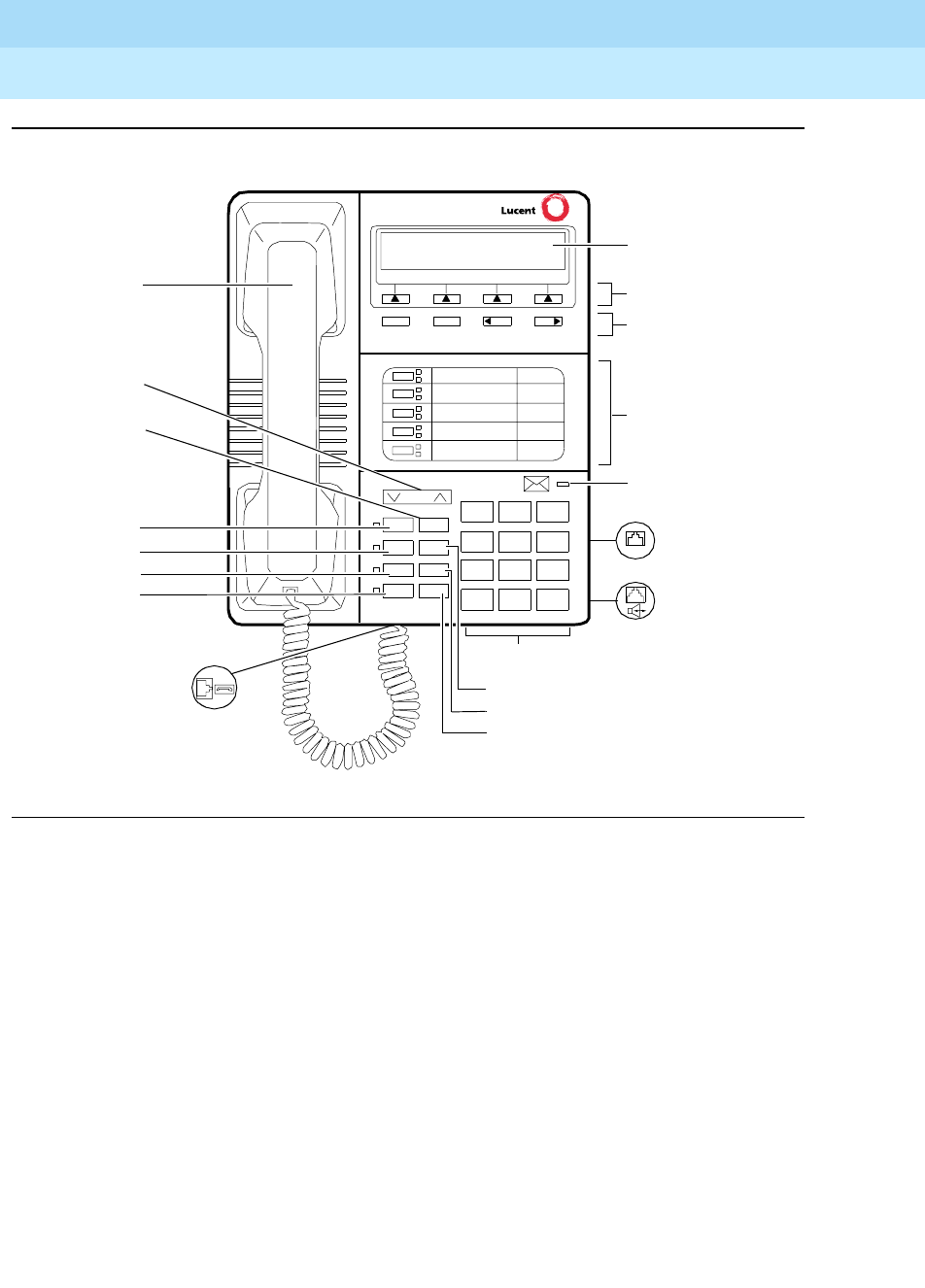
DEFINITYEnterpriseCommunicationsServerandSystem75andSystem85
Terminals and Adjuncts Reference
555-015-201 Issue 11
December 1999
The 8400 Series Voice Terminals
12-17The 8405B, 8405B Plus, 8405D, and 8405D Plus Voice Terminals
12
Figure 12-8. Another Version of the 8405D and 8405D Plus
There are four varieties of the 8405 voice terminal: the 8405B and 8405B Plus,
the 8405D and 8405D Plus. All four varieties are multi-appearance digital
telephones with five call appearance/feature buttons. All of the 8405 voice
terminals also have four standard fixed feature buttons (CONFERENCE, DROP,
HOLD, and TRANSFER), a MUTE button, a SPEAKER button, a TEST button,
and a Volume control button. In addition, some 8405 voice terminals have a blue
SHIFT button; others have a RING button instead.
However, these four 8405 variations have the following differences:
■The 8405B has a 1-way, listen-only speaker, with NO display.
■The 8405B Plus has a 2-way speakerphone, without a display.
■The 8405D has a 1-way, listen-only speaker and a 2-line by 24-character
display.
■The 8405D Plus has a 2-way speakerphone and a 2-line by 24-character
display.
Volume
Ring Transfer
Test Conf
Mute Drop
Speaker Hold
123
456
789
ABC DEF
MNOJKLGHI
PQRS TUV WXYZ
*
O#
Dial pad
Handset
Hold button
Transfer
Conference button
Ring button
5 Call appearance/
feature buttons
Message light
Test button
Mute button
Speaker button
Softkeys
Display
NextPrevMenu Exit
Display
control
buttons
Handset jack
Line jack (on back
of voice terminal)
Speakerphone/
headset adapter
jack (on back of
voice terminal)
Drop button
Volume
LINE
button
control
button

DEFINITYEnterpriseCommunicationsServerandSystem75andSystem85
Terminals and Adjuncts Reference
555-015-201 Issue 11
December 1999
The 8400 Series Voice Terminals
12-18The 8405B, 8405B Plus, 8405D, and 8405D Plus Voice Terminals
12
Those users who have an 8405D or an 8405D Plus can access 12 features with
the softkeys and display control buttons. These 12 features can be used
in
addition to
the features on the call appearance/feature buttons.
The 8405 voice terminal can work in both 4-wire and 2-wire environments. For
more information, see “Wiring Information.”
NOTE:
As of September 1, 1998, the 8405B Plus (with speakerphone) and the
8405D (with display and listen-only speaker) will be discontinued.
Applications
The 8405 voice terminal can be used with the DEFINITY Communications System
Generic 1, Generic 2, and Generic 3, the DEFINITY ECS, System 75, and System
85. This type of voice terminal is especially suitable for managers, executive
secretaries, and other office support personnel who require access to multiple
lines for call handling, call coverage, bridging, conferencing, and sophisticated
voice communications. The display set can be used by those who have a need for
calling party display capabilities or who require a large number of voice terminal
features.
The 8405 voice terminals can also provide the user with simultaneous voice and
data communications. The 8405 can be connected to a 7400B Plus Data Module
or 8400B Plus Data Module. With the 8405 voice terminal, PC platform products
can be useful in providing voice capabilities since these screen-based products
can greatly enhance the telephone capabilities of these voice terminals.
Physical Features
Dimensions
NOTE:
The dimensions described here for the 8405 voice terminal are approximate.
Width = 7.8 inches
Depth (front to back) = 9.5 inches
Height (maximum with handset in place) = low position, 5.265 inches
high position, 6.625 inches

DEFINITYEnterpriseCommunicationsServerandSystem75andSystem85
Terminals and Adjuncts Reference
555-015-201 Issue 11
December 1999
The 8400 Series Voice Terminals
12-19The 8405B, 8405B Plus, 8405D, and 8405D Plus Voice Terminals
12
Features
Eight Fixed Feature Buttons
The 8405 has the following eight fixed feature buttons:
■CONFERENCE (labeled CONF) button
■DROP button
■TRANSFER button
■A red HOLD button
■Either a blue SHIFT button or a RING button
■MUTE button
■SPEAKER button
■TEST button
The SHIFT Button
Some 8405 voice terminals have a blue SHIFT button that can be used in the
following ways: (The red light next to the SHIFT button goes on steadily when the
button is activated.)
■On all 8405 sets, this button can be used with the HOLD button to select
your own personalized ring from among eight available patterns.
■On the 8405B Plus and the 8405D Plus, this button can be used with the
SPEAKER button to perform an acoustic test of the environment and adjust
the speakerphone to the surrounding acoustic environment for optimal
performance.
The RING Button
On other 8405 voice terminals the user can press the RING button in order to
select a personalized ringing pattern for the voice terminal. There are eight ringing
patterns from which to choose.
Call Appearance/Feature Buttons
All 8405 voice terminals have five call appearance/feature buttons, each equipped
with a red light and a green status light. Usually, at least two of these buttons are
administered as call appearances for the terminal’s primary extension number,
where calls are placed and answered. The remainder of the buttons can be used
for more call appearances (including bridged appearances of other stations’
extensions) and features. Buttons administered for features have only their green
status lights active.
Message Light
The red Message light goes on when a message is left for the user. It goes off
when the user retrieves the message or when the message is erased. This light is
labeled either
Message
or .

DEFINITYEnterpriseCommunicationsServerandSystem75andSystem85
Terminals and Adjuncts Reference
555-015-201 Issue 11
December 1999
The 8400 Series Voice Terminals
12-20The 8405B, 8405B Plus, 8405D, and 8405D Plus Voice Terminals
12
Speaker (Listen-Only) Feature
The 8405B and the 8405D have a 1-way, listen-only speaker. The 8405B Plus and
the 8405D Plus have a two-way speakerphone; however, these two voice
terminals can be optioned instead for a 1-way, listen-only speaker. If this is the
case, use the SPEAKER button on the front of the voice terminal for turning on
and off the speaker.
The Speaker (listen-only) capability allows a user to engage in a 1-way
conversation with the far-end. Specifically, the user can only listen to the far-end.
To speak with the far-end, the user must use the handset which turns off the
speaker. The Speaker function may also be disabled.
Speakerphone
The 8405B Plus and the 8405D Plus voice terminals are equipped with a built-in
2-way speakerphone. (The voice terminal can be optioned for a 1-way, listen-only
speaker instead. The system manager should have records of how this feature is
optioned.) The Speakerphone capability allows a user to engage in a hands-free
conversation with the far-end party. The speakerphone can be turned on or off
with the SPEAKER button; can be muted with the MUTE button, and the volume
can be raised and lowered with the VOLUME “arrow” button.
If the voice terminal has a SHIFT button and
Rest Spkr
appears below the
SPEAKER button, the user can access the Reset Speakerphone feature to adjust
the speakerphone for optimal performance.
NOTE:
If there is not a SHIFT button and Reset Spkr does NOT appear under the
SPEAKER button, the voice terminal will adjust to the surrounding
environment by itself. The user does not need to do anything manually.
By pressing the blue SHIFT button on the set and then the SPEAKER button (if
the user has an 8405B Plus or an 8405D Plus and the voice terminal is set for the
Speakerphone feature), the user hears a set of tones as the speakerphone
performs an acoustic test of the environment. When the tones stop, the
speakerphone has finished adjusting itself and is ready for use. The user
must
reset the speakerphone in any of three instances: whenever the voice terminal is
moved to another place (even in the same room), whenever the red light next to
the SPEAKER button is fluttering, and, when, in the unlikely event, the
speakerphone is making a squealing sound.
MUTE Button
The MUTE button is a fixed feature button with a red status light. The MUTE
button turns off the microphone of the built-in speakerphone (only on the 8405B
Plus and 8405D Plus) or the handset so that a person can converse with another
person in the room without the other party listening in.
DEFINITYEnterpriseCommunicationsServerandSystem75andSystem85
Terminals and Adjuncts Reference
555-015-201 Issue 11
December 1999
The 8400 Series Voice Terminals
12-21The 8405B, 8405B Plus, 8405D, and 8405D Plus Voice Terminals
12
VOLUME Control Button
The 8405 voice terminal has a VOLUME “arrow” button on the front of the set.
This button has several functions. When the user is using the speakerphone or the
1-way speaker, the VOLUME button controls the volume of the speaker. When the
user is on a call using the handset, the VOLUME button controls the handset
volume. When the voice terminal is idle, the button controls the volume of the tone
ringer.
When the user sets the volume for the speaker, speakerphone, handset, or the
tone ringer, the display on the 8405D voice terminal shows a “bar array” that
indicates the volume setting.
TEST Button
When the voice terminal is initially powered up, the green light next to the TEST
button flashes if the link with the PBX is not (or not yet) operational. The light
changes to steady green when the voice terminal is able to communicate with the
PBX. After the voice terminal is powered up, you can press the TEST button to
test the lights and the display (on the 8405D and 8405D Plus) on your voice
terminal.
Display
The display on the 8405D and the 8405D Plus has two lines with 24 characters on
each line. The display, along with the softkeys and the display control buttons, can
be used to access 12 softkey features (the default softkey features and the
alternative softkey features are listed under “Softkeys”).
Display Control Buttons
These four buttons are labeled ,, , and .
■is used to enter Softkey Mode and access the 12 softkey features.
■is used for exiting a display feature and returning to Normal
(call-handling) Mode.
■and can be used to go back and forth through the feature
option screens.
Softkeys
The four buttons located below the display and labeled with arrows correspond to
features listed on the second line of the display screen. (There are four features
on each feature option screen.) The user can access any of the 12 features by
pressing the softkey below the feature abbreviation.
Menu Exit Prev Next
Menu
Exit
Prev Next
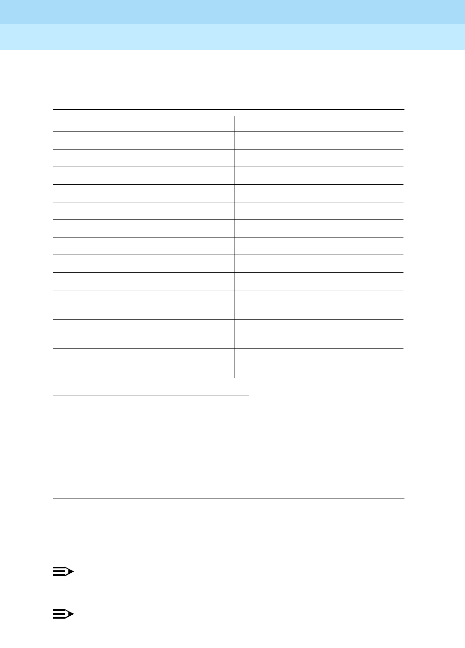
DEFINITYEnterpriseCommunicationsServerandSystem75andSystem85
Terminals and Adjuncts Reference
555-015-201 Issue 11
December 1999
The 8400 Series Voice Terminals
12-22The 8405B, 8405B Plus, 8405D, and 8405D Plus Voice Terminals
12
Below is a list of the 12 default softkey features assigned to the 8405D and 8405D
Plus and the order in which they appear.
On 8405D and 8405D Plus voice terminals connected to a DEFINITY G3V3 or
later, the System Manager can choose to administer alternate features for use
with the softkeys. The following table lists some of the alternate softkey features
that can be substituted for the default softkey features listed on the previous page.
NOTE:
The DEFINITY ECS, Release 5 (and later releases) may provide additional
alternate softkey features.
NOTE:
With a DEFINITY G3V3 and later, the system can download
BLANK
softkey
labels for positions where there are no features administered.
Table 12-4. Default Softkey Features on the 8405D and 8405D Plus
Abbreviation Feature
First Screen LWC Leave Word Calling
CnLWC Cancel Leave Word Calling
AutCB Automatic Callback
Timer Timer
Second Screen CFrwd*
* On a DEFINITY Generic 2 or System 85 switches, this feature is named Call Forward -
Follow Me.
Call Forward
CPark†
† On a DEFINITY G2 and System 85, there is no Call Park feature that can be assigned
to a feature button. In order to have the Call Park function on a softkey or hard button,
administer the button as an Abbreviated Dial button and program the Call Park trunk
group access code onto it. This button can then be labeled “Call Park.” In addition, on
a DEFINITY G2 or System 85, the Recall feature must be administered on a standard
feature button.
Call Park
TmDay Time/Date
PCall Priority Calling
Third Screen Prog Abbreviated Dialing Program
Pause Abbreviated Dialing Special
Function Pause
Mark Abbreviated Dialing Special
Function Mark
Wait Abbreviated Dialing Special
Function Wait

DEFINITYEnterpriseCommunicationsServerandSystem75andSystem85
Terminals and Adjuncts Reference
555-015-201 Issue 11
December 1999
The 8400 Series Voice Terminals
12-23The 8405B, 8405B Plus, 8405D, and 8405D Plus Voice Terminals
12
Table 12-5. Alternate Softkey Features on the 8405D and 8405D Plus
Connected to a DEFINITY G3V3 and Later
Abbreviation Feature
AD Abbreviated Dialing buttons (can be multiple AD buttons)
Cnslt Consult
Count ACD Stroke Count
CPkup Call Pickup
Dir*
* A CALL DISPLAY button should be administered, if access to System Directory is
provided. It is also desirable for a NEXT DISPLAY button to be administered. This
feature is
not
available on the DEFINITY G2 or System 85.
Directory
Excl Manual Exclusion
HFAns†
† This feature is available only on the DEFINITY G3V2 (or later).
Internal Auto Answer
IAuto Intercom Auto
IDial Intercom Dial
Inspt Inspect
Last Last Number Dialed
RngOf Ringer Off
SAC Send All Calls
SFunc Abbreviated Dialed Special Function
Spres Abbreviated Dialing Special Function Suppress
Stats View (ACD) Statistics
Stop Abbreviation Dialing Indefinite Wait or Stop
View‡
‡ This feature is
not
available on a DEFINITY G2 or System 85.
Stored Number

DEFINITYEnterpriseCommunicationsServerandSystem75andSystem85
Terminals and Adjuncts Reference
555-015-201 Issue 11
December 1999
The 8400 Series Voice Terminals
12-24The 8405B, 8405B Plus, 8405D, and 8405D Plus Voice Terminals
12
Other Physical Features
Handset
The 8405 voice terminal is equipped with a K-type handset.
Dial pad
The 8405 voice terminal has a 12-button touch-tone dial pad. The letters “Q” and
“Z” have been added to the appropriate dial pad keys for directory access, and the
“5” button on the dial pad has raised bars for visually-impaired users.
Jacks
The 8405 voice terminal’s housing has a Line jack located on the back of the
housing, and a Handset cord jack located on the side of the set. There is also a
Speakerphone/headset adapter jack to which the user can connect adjunct
equipment.
Cords
Two cords are supplied with the 8405: a coiled 9-foot handset cord and a 7-foot
line cord.
Optional longer cords are available: a 12-foot handset cord and 14-foot and
25-foot line cords.
Ringing
The 8405 voice terminal has electronic tone ringing with eight possible ringing
patterns that can be selected with the RING button on some 8405 voice terminals;
on other voice terminals, the user presses the SHIFT button and the HOLD button
in order to choose a ringing pattern.
The loudness of the tone ringer can be controlled by the VOLUME “arrow” button.
(The user must NOT be on a speakerphone call. If the user is using the
speakerphone, the VOLUME “arrow” button controls the volume of the
speakerphone.)
Mounting Options
The 8405 voice terminal comes equipped with a 2-position desk stand. This stand
can also be removed so the user can mount the set on the wall.
Color Options
The 8405 voice terminal is available in black and in white.
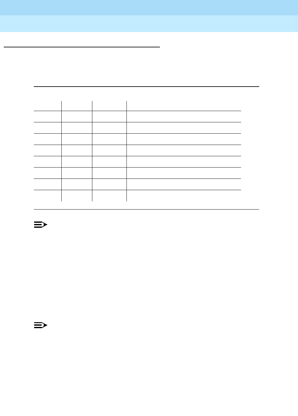
DEFINITYEnterpriseCommunicationsServerandSystem75andSystem85
Terminals and Adjuncts Reference
555-015-201 Issue 11
December 1999
The 8400 Series Voice Terminals
12-25The 8405B, 8405B Plus, 8405D, and 8405D Plus Voice Terminals
12
Wiring Information
The 8405 voice terminal works in both 4-wire and 2-wire DCP configurations. The
table below describes the pins on an 8400-Series voice terminal LINE jack.
NOTE:
Regardless of which configuration is in use, ALL wiring between the PBX
and the terminal MUST consist of twisted-pairs, including the modular line
cord. The line cord must be a D8W, which consists of 4 twisted-pairs, or a
Lucent Technologies-approved equivalent.
Twisted-pair wiring is used to make lines less sensitive to crosstalk.
Therefore, failure to use twisted pair wiring may result in less-than-optimum
performance of the terminal and may contribute to problems with the line.
An 8-wire modular cord MUST be used for all 4-wire and any 2-wire
installations requiring auxiliary power.
NOTE:
You do NOT need to change any settings on the voice terminal for 2-wire or
4-wire installations. The voice terminal is able to detect whether it is in a
2-wire or a 4-wire configuration.
For 2-wire operation, if you need to plug the voice terminal into a 4-pin or
6-pin wall jack, instead of a standard 8-pin modular jack, refer to the “Line
Interface” table to insure that the wires from the 4-pin or 6-pin wall jack are
connected to the correct pins on the terminal “LINE” jack.
Table 12-6. The Pins on an 8400-Series Voice Terminal LINE Jack
Line Interface
Pin Pair Name Description
1 2 OD1 4-Wire Output
2 2 OD2 4-Wire Output
3 3 ID1 4-Wire Input
41 U-T2-Wire(Tip)
5 1 U-R 2-Wire (Ring)
6 3 ID2 4-Wire Input
7 4 P1- Adjunct Power -48V
8 4 P2+ Adjunct Power Common
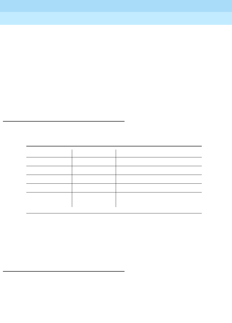
DEFINITYEnterpriseCommunicationsServerandSystem75andSystem85
Terminals and Adjuncts Reference
555-015-201 Issue 11
December 1999
The 8400 Series Voice Terminals
12-26The 8405B, 8405B Plus, 8405D, and 8405D Plus Voice Terminals
12
In order for the terminal to function properly in either 2-wire or 4-wire installations,
there must be NO INTERCONNECTIONS between the wire pairs used for 2-wire
and 4-wire operations. Bridging or paralleling of these pairs can result in damage
to the terminal or can cause the PBX circuit pack to remove power to the terminal.
REMOVE ALL CONNECTIONS BETWEEN PAIRS BEFORE CONNECTING THE
TERMINAL.
4-WIRE installations MUST ONLY have PBX connections on pair 2 and pair 3
and, if necessary, auxiliary power must be connected to pair 4.
2-WIRE installations MUST ONLY have PBX connections on pair 1 and, if
necessary, auxiliary power must be connected to pair 4.
Distance Limitations
The following circuit packs can be used with all of the 8400-Series sets.
In 4-wire operation, the voice terminal must be within 5,000 feet of the PBX using
22-gauge or 24-gauge wire, and within 4,000 feet of the PBX using 26-gauge wire.
In 2-wire operation, the voice terminal must be within 5,500 feet of the PBX using
22-gauge wire, within 3,500 feet of the PBX using 24-gauge wire, and within 2,200
feet of the PBX using 26-gauge wire.
Power Requirements
The 8405 voice terminal receives power from the system and does not require any
external power supply. Additional external power IS required when the 8405 voice
terminal is equipped with any adjuncts, such as an external speakerphone. In this
instance, a 1151A1 local power supply or a 1151A2 power supply with Battery
Holdover is recommended. Refer to the Adjunct Power section earlier in this
manual for more information on these power supplies.
Table 12-7. Circuit Packs Used with the 8400-Series Voice Terminals
Circuit Pack 2/4-Wire Will support these switches
TN2181 - 16-port 2-wire G3V2 and later
TN754b - 8-port 4-wire All switches except System 85
TN754 - 8-port 4-wire All switches except System 85
TN413 - 8-port 4-wire International System 75
SN 270 and
SN 270B - 4-port 4-wire System 85 R2V2 - R2V4
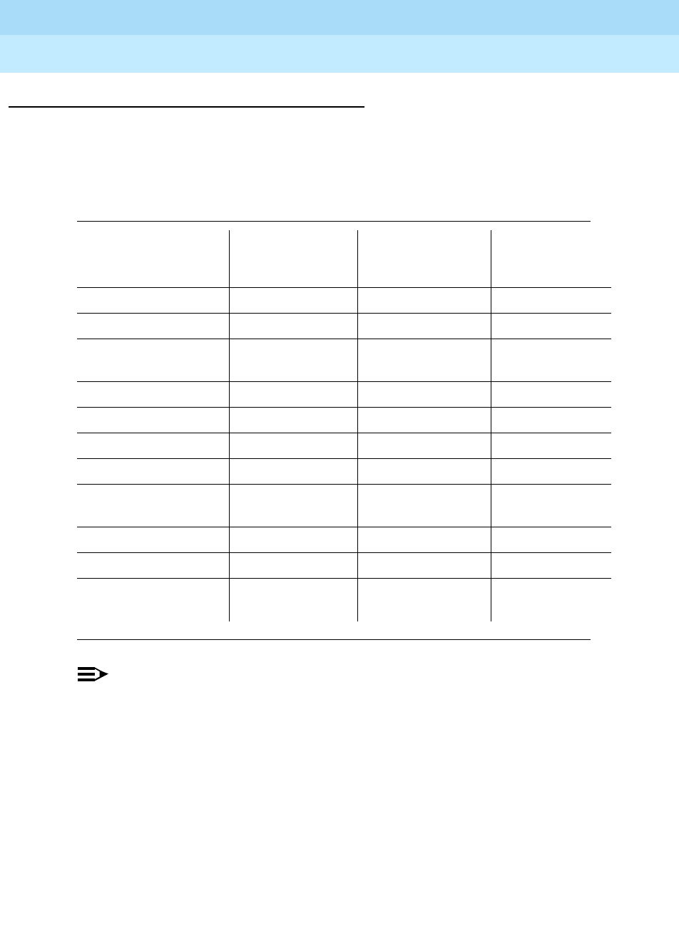
DEFINITYEnterpriseCommunicationsServerandSystem75andSystem85
Terminals and Adjuncts Reference
555-015-201 Issue 11
December 1999
The 8400 Series Voice Terminals
12-27The 8405B, 8405B Plus, 8405D, and 8405D Plus Voice Terminals
12
Switch Administration
Aliasing
Use the following table for administering 8405B and 8405B Plus voice terminals:
NOTE:
When administering the 8405B and 8405D voice terminal on a DEFINITY
G3V4 or a DEFINITY ECS, you must select “One-way” or “None” as the
speaker option on the 8410 Administration Form. If the voice terminal is
incorrectly optioned as having a two-way speakerphone, the light next to the
Speaker button will continually flutter. In that case, you must readminister
the terminal.
Table 12-8. Administering the 8405B and 8405B Plus Voice Terminals
If you have this
System and this Release
(which can
support this type
of operation)
Administer
8405B or 8405B
Plus as a
System 75 R1V1 — R1V3 4-wire only 7403D
System 85 R2V2 — R2V4 4-wire only 7403D
International System
75 IR1V4, etc. 4-wire only 7403D
DEFINITY G1 4-wire only 7403D
Global DEFINITY ’91 4-wire only 7410D
DEFINITY G2V1 4-wire only 7410D
DEFINITY G2V2 4-wire only 7410D
DEFINITY G3i,
G3r,G3s, G3vs 4-wire only 7410D
DEFINITY G3V2 2- or 4-wire 7410D
DEFINITY G3V3 2- or 4-wire 8410B
DEFINITY G3V4 and
later 2- or 4-wire 8405B or
8405B Plus
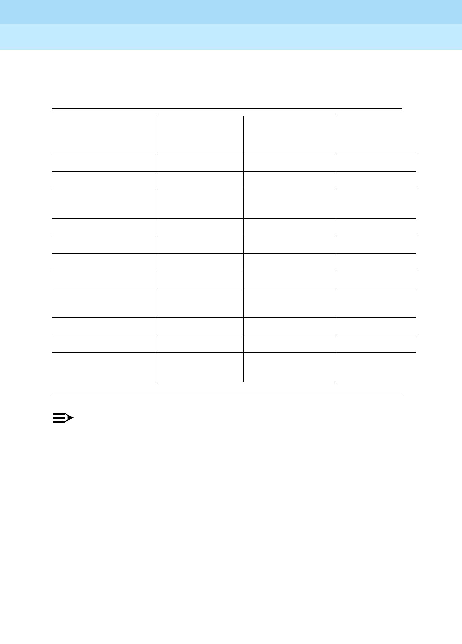
DEFINITYEnterpriseCommunicationsServerandSystem75andSystem85
Terminals and Adjuncts Reference
555-015-201 Issue 11
December 1999
The 8400 Series Voice Terminals
12-28The 8405B, 8405B Plus, 8405D, and 8405D Plus Voice Terminals
12
Use the following table for administering the 8405D and 8405D Plus voice
terminals:
NOTE:
When administering the 8405B and 8405D voice terminal on a DEFINITY
G3V4 or a DEFINITY ECS, you must select “One-way” or “None” as the
speaker option on the 8410 Administration Form. If the voice terminal is
incorrectly optioned as having a two-way speakerphone, the light next to the
Speaker button will continually flutter. In that case, you must readminister
the terminal.
Button Numbering
The following button diagrams of the 8405 voice terminals will help you administer
all four versions of this voice terminals connected to a System 75, DEFINITY G1
and G3, or DEFINITY ECS, and to a System 85 or a DEFINITY G2.
Figure 12-9 shows button numbering for the 8405 connected to a System 75,
DEFINITY G1 and G3, or DEFINITY ECS. Figure 12-10 shows button numbering
for the 8405 connected to a System 85 or DEFINITY G2.
Table 12-9. Administering the 8405D and 8405D Plus Voice Terminals
If you have this
System and this Release
(which can
support this type
of operation)
Administer the
8405D or 8405D
Plus as a
System 75 R1V1 — R1V3 4-wire only 7405D+D
System 85 R2V2 — R2V4 4-wire only 7405D+D
International System
75 IR1V4, etc. 4-wire only 7405D+D
DEFINITY G1 R1V4 4-wire only 7405D+D
Global DEFINITY ’91 4-wire only 7405D+D
DEFINITY G2V1 4-wire only 7405D+D
DEFINITY G2V2 4-wire only 7405D+D
DEFINITY G3i, G3r,
G3s, G3vs 4-wire only 7405D+D
DEFINITY G3V2 2- or 4-wire 7405D+D
DEFINITY G3V3 2- or 4-wire 8410D
DEFINITY G3V4 and
later 2- or 4-wire 8405D or
8405D Plus
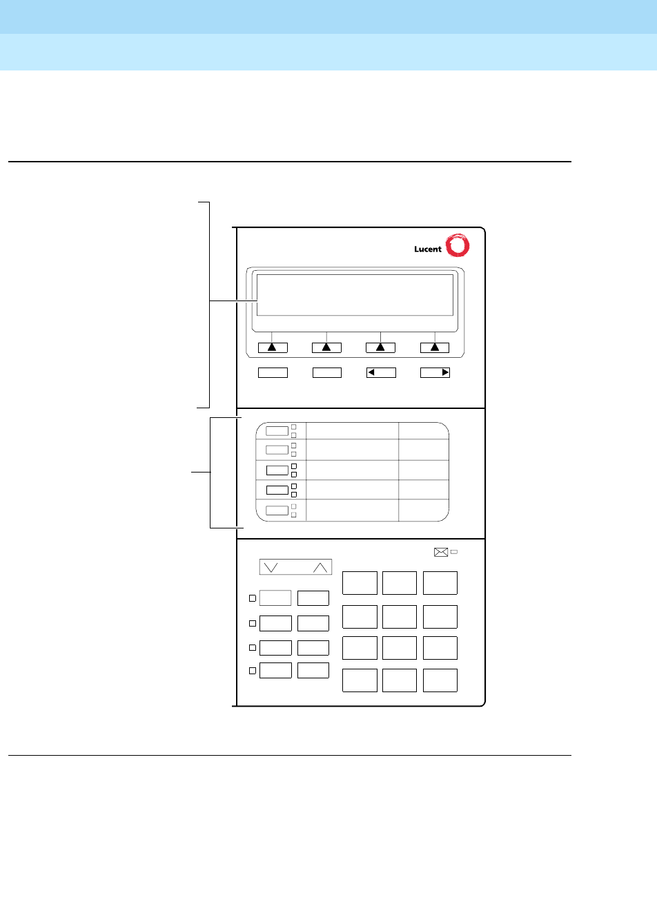
DEFINITYEnterpriseCommunicationsServerandSystem75andSystem85
Terminals and Adjuncts Reference
555-015-201 Issue 11
December 1999
The 8400 Series Voice Terminals
12-29The 8405B, 8405B Plus, 8405D, and 8405D Plus Voice Terminals
12
If you need more information, refer to
DEFINITY Communications System
Generic 3 Implementation
, 555-230-653, and
DEFINITY Communications System
Generic 2 Administration of Features and Hardware
, 555-104-507.
Figure 12-9. Button Numbering for Administering the 8405 Voice Terminal Connected to
a System 75, a DEFINITY G1 or G3, or a DEFINITY ECS
Volume
Ring Transfer
Test Conf
Mute Drop
Hold
123
456
789
ABC DEF
MNOJKLGHI
PQRS TUV WXYZ
*
O#
NextPrevMenu Exit
If the 8405D or
8405D Plus is
administered as a
7405D, administer the
12 softkey features on
“FEATURE BUTTON
ASSIGNMENTS”
2 through 13; administer
The 5 call appearance/
feature buttons
are administered
as “BUTTON
ASSIGNMENTS”
1 through 5.
1
2
3
4
5
the Normal feature on
Button #1.
If the 8405D or
8405D Plus is
administered as an
8410D, administer the
12 softkey features on
“SOFTKEY BUTTON
ASSIGNMENTS”
1 through 12.
Speaker
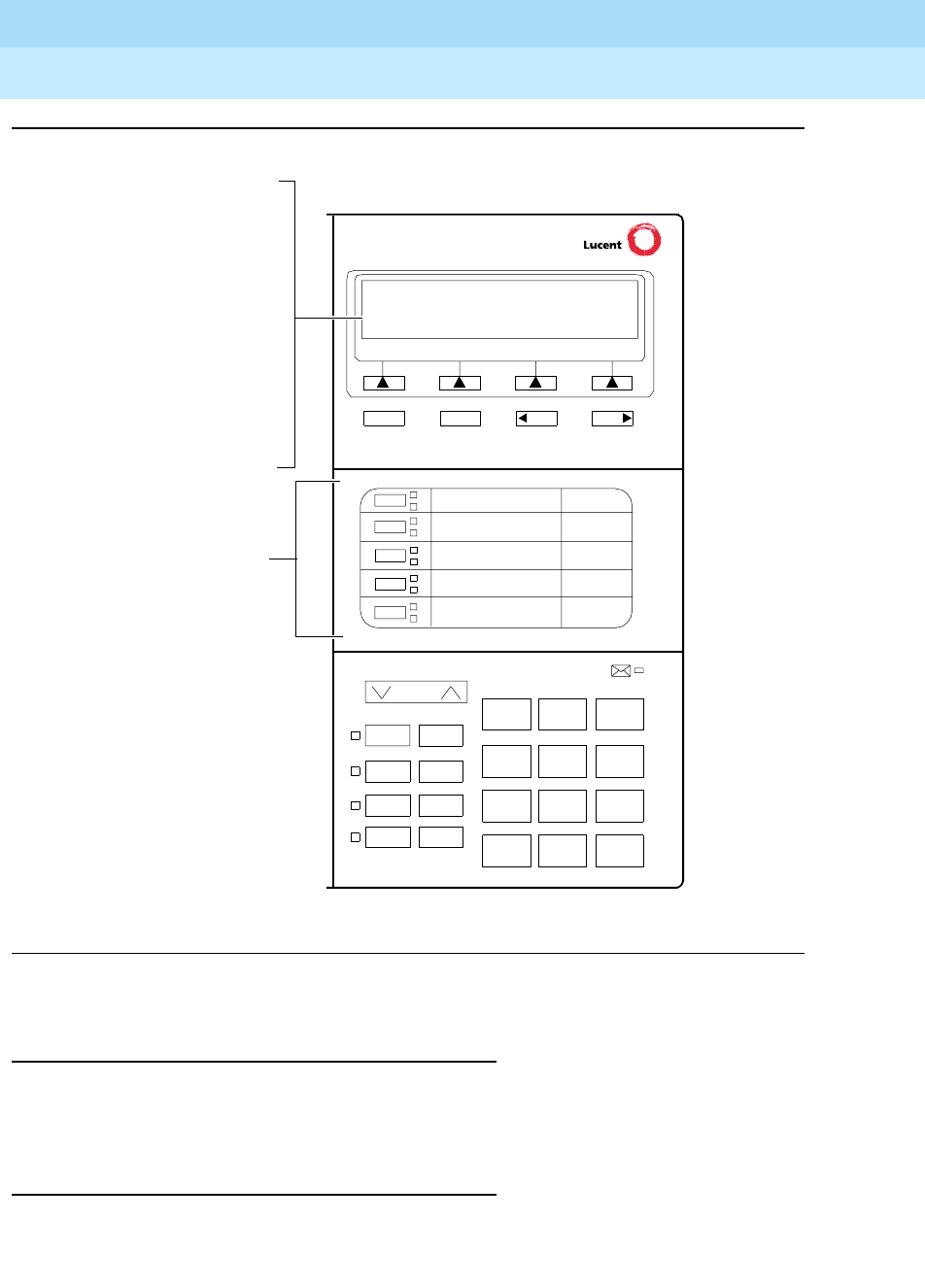
DEFINITYEnterpriseCommunicationsServerandSystem75andSystem85
Terminals and Adjuncts Reference
555-015-201 Issue 11
December 1999
The 8400 Series Voice Terminals
12-30The 8405B, 8405B Plus, 8405D, and 8405D Plus Voice Terminals
12
Figure 12-10. Button Numbering for Administering the 8405 Voice Terminal Connected
to a System 85 or a DEFINITY G2
Power Failure Operation
The 8405 voice terminal cannot be used as an emergency station during power
failure transfer conditions.
FCC Registration
The 8405 voice terminal is FCC-registered along with the switch (as a system),
but does not have a separate FCC registration label.
Volume
Ring Transfer
Test Conf
Mute Drop
Hold
123
456
789
ABC DEF
MNOJKLGHI
PQRS TUV WXYZ
*
O#
NextPrevMenu Exit
If the 8405D or
8405D Plus is
administered as a
7405D, administer the
12 softkey features on
“FEATURE BUTTON
ASSIGNMENTS” 14
through 25; administer
The 5 call appearance/
feature buttons
are administered
as “BUTTON
ASSIGNMENTS”
3 through 7.
3
4
5
6
7
the Normal feature on
Button #13.
If the 8405D or
8405D Plus is
administered as an
8410D, administer the
12 softkey features on
“SOFTKEY BUTTON
ASSIGNMENTS”
1 through 12.
Speaker

DEFINITYEnterpriseCommunicationsServerandSystem75andSystem85
Terminals and Adjuncts Reference
555-015-201 Issue 11
December 1999
The 8400 Series Voice Terminals
12-31The 8405B, 8405B Plus, 8405D, and 8405D Plus Voice Terminals
12
UL and CSA Approval
The 8405 voice terminal has been tested and has met the Underwriters
Laboratories (UL) Standards UL 1459 and has also met the Canadian Standards
Association (CSA) Standards CSA-C22.2 No.225-M90.
Hearing Aid Compatible
All 8405 voice terminals are compatible with the inductively coupled hearing aids
prescribed by the FCC.
8405 Equipment PECs and Comcodes
The 8405 voice terminals and components can be ordered with these PECs and
Comcodes:
■8405B (8405D08A) Voice Terminal (without display, with one-way
speaker)
Black 8405B Set PEC: 3233-5BB
Comcode: 107858847;
White 8405B Set PEC: 3233-5BW
Comcode: 107858854
■8405B Plus (8405D06A) Voice Terminal (without display, with two-way
speakerphone)
Black 8405B Plus Set PEC: 3233-5SB
Comcode: 107858359;
White 8405B Plus Set PEC: 3233-5SW
Comcode: 107858367
■8405D (8405D07A) Voice Terminal (with built-in display and one-way
speaker)
Black 8405D Set PEC: 3233-6BB
Comcode: 107858615;
White 8405D Set PEC: 3233-6BW
Comcode: 107858623
■8405D Plus (8405D05A) Voice Terminal (with built-in display and
two-way speakerphone)
Black 8405D Plus Set PEC: 3233-6SB
Comcode: 107858110;
White 8405D Plus Set PEC: 3233-6SW
Comcode: 107858128
■K2S8 Handset
Comcode: Black=107545584; White=107545568
■Handset cord (9 feet)
Comcode: Black=407632819; White=407632835
■Line cord (7 feet)
Comcode: 103786778

DEFINITYEnterpriseCommunicationsServerandSystem75andSystem85
Terminals and Adjuncts Reference
555-015-201 Issue 11
December 1999
The 8400 Series Voice Terminals
12-32The 8405B, 8405B Plus, 8405D, and 8405D Plus Voice Terminals
12
■Line cord (14 feet, silver)
PEC: 2725-07N (COL18)
Comcode: 103786828
■Line cord (25 feet, silver)
PEC: 2725-07S (COL18)
Comcode: 103786802
■Button Designation Card
Tractor Feed For 25 Sets
PEC: 32310A
Comcode: 847770666;
Tractor Feed For 100 Sets
PEC: 32311A
Comcode: 847770674
Adjuncts
The following adjuncts can be used with the 8405 voice terminal:
■S101A Speakerphone (no longer orderable)
■S201A Speakerphone
■CS201A Speakerphone
■7400B Plus Data Module
■8400B Plus Data Module
■500A1 Headset Adapter (and a standard headset; see “Headsets” below)
■K6S2 Amplifier Handset
■Shoulder Rest
Headsets
A list of compatible headsets, consisting of both modular and plug prong base
units and selection of headpieces, appears in “Headset Adapters” in the Adjuncts
section later in this manual.

DEFINITYEnterpriseCommunicationsServerandSystem75andSystem85
Terminals and Adjuncts Reference
555-015-201 Issue 11
December 1999
The 8400 Series Voice Terminals
12-33The 8405B, 8405B Plus, 8405D, and 8405D Plus Voice Terminals
12
Additional Documents
The following documents contain additional information relating to the 8405 voice
terminal: (Use the 9 digit number listed after each document to order that book
from the BCS Publications Center for Lucent Technologies.)
■
The 8400-Series Voice Terminals Installation and User’s Manual
,
555-230-875
■
The 8400-Series Voice Terminals Instructions for Installation, Switch
Administration, and Programming the Options
, 555-015-725
■
DEFINITY Enterprise Communications Server Generic 1 and System 75
8405 Voice Terminal User’s Guide
, 555-230-736
■
DEFINITY Enterprise Communications Server Generic 1 and 3 and
System 75 8405 Quick Reference Guide
, 555-230-737
■
DEFINITY Enterprise Communications Server Generic 2 and System 85
8405 Voice Terminal User’s Guide
, 555-104-726
■
DEFINITY Enterprise Communications Server Generic 2 and System 85
8405 Quick Reference Guide
, 555-104-725
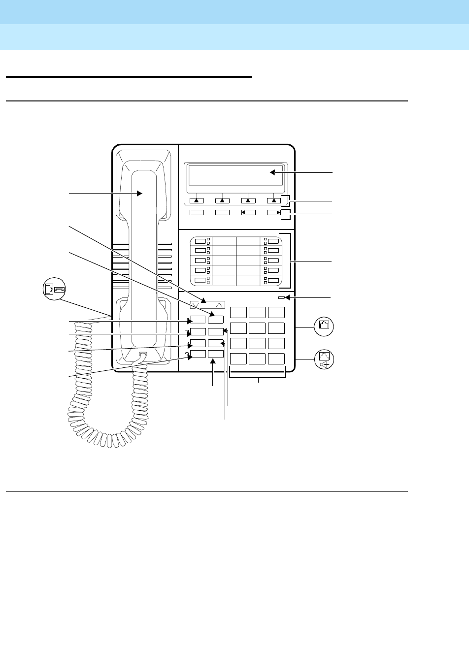
DEFINITYEnterpriseCommunicationsServerandSystem75andSystem85
Terminals and Adjuncts Reference
555-015-201 Issue 11
December 1999
The 8400 Series Voice Terminals
12-34The 8410 Voice Terminal
12
The 8410 Voice Terminal
Figure 12-11. One Version of the 8410D Voice Terminal (with Display)
Volume
Shift Transfer
Test Conf
Mute Drop
Speaker Hold
Reset Spkr
123
456
789
ABC DEF
MNOJKLGHI
PQRS TUV WXYZ
*
O#
Dial Pad
Shift Button
10 Call
Message
Test Button
Mute Button
Speaker/
4 Softkeys
4 Display
8410D
NextPrevMenu Exit
Display
LINE
Line Jack
Speakerphone/
Ring
Drop Button
(on back of
Headset
Light
Appearance/
Feature
Buttons
Adapter Jack
Control
Buttons
Reset
Speaker
Button
Handset
Jack (on
left side of
Message
Transfer
Volume
Handset
Control
Button
Button
terminal)
Conference Button
terminal)
(on back of
terminal)
Hold/Ring Button
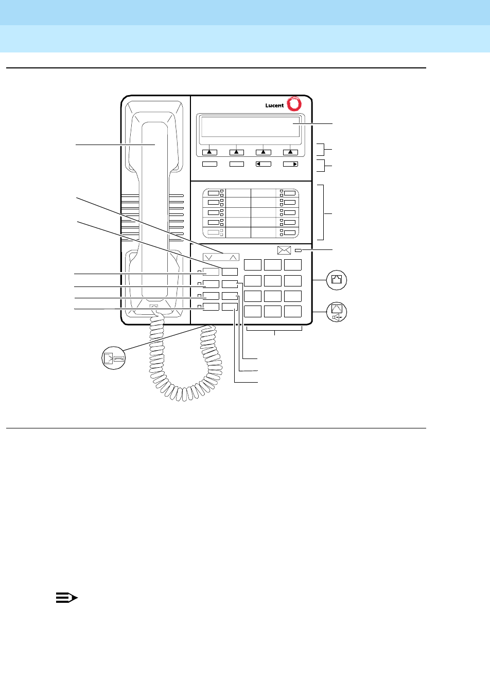
DEFINITYEnterpriseCommunicationsServerandSystem75andSystem85
Terminals and Adjuncts Reference
555-015-201 Issue 11
December 1999
The 8400 Series Voice Terminals
12-35The 8410 Voice Terminal
12
Figure 12-12. Another Version of the 8410D Voice Terminal
The 8410 voice terminal is a multi-appearance digital telephone with 10 call
appearance/feature buttons, four standard fixed feature buttons (CONFERENCE,
DROP, HOLD, and TRANSFER), a MUTE button, a SPEAKER button which can
access either a 2-way speakerphone or a 1-way, listen-only speaker, a TEST
button, and a Volume control button. In addition, some 8410 voice terminals have
a blue SHIFT button; other 8410 voice terminals have a RING button instead.
There are two varieties of the 8410 voice terminal: the 8410B (8410D04A) is the
basic set, without a display; the 8410D (8410D03A) has a built-in 2-line by
24-character display.
NOTE:
The 8410D01A and 8410D02A are older versions of this voice terminal and
are no longer available.
Those users who have an 8410D with display can access 12 features with the
softkeys and display control buttons. These 12 features can be used
in addition to
the features on the call appearance/feature buttons.
Volume
Ring Transfer
Test Conf
Mute Drop
Speaker Hold
123
456
789
ABC DEF
MNOJKLGHI
PQRS TUV WXYZ
*
O#
Dial pad
Handset
Hold button
Transfer
Conference button
Ring button
10 Call appearance/
feature buttons
Message light
Test button
Mute button
Speaker button
Softkeys
Display
NextPrevMenu Exit
Display
control
buttons
Handset jack
Line jack (on back
of voice terminal)
Speakerphone/
headset adapter
jack (on back of
voice terminal)
Drop button
Volume
LINE
button
control
button

DEFINITYEnterpriseCommunicationsServerandSystem75andSystem85
Terminals and Adjuncts Reference
555-015-201 Issue 11
December 1999
The 8400 Series Voice Terminals
12-36The 8410 Voice Terminal
12
The 8410 voice terminal can work in both 4-wire and 2-wire environments. For
more information, see “Wiring Information.”
Applications
The 8410 voice terminal can be used with the DEFINITY Communications System
Generic 1, Generic 2, or Generic 3, the DEFINITY ECS, System 75, and
System 85. This type of voice terminal is especially suitable for managers,
executive secretaries, and other office support personnel who require access to
multiple lines for call handling, call coverage, bridging, conferencing, and
sophisticated voice communications. The display set can be used by those who
have a need for calling party display capabilities or who require a large number of
voice terminal features.
The 8410 voice terminals can also provide the user with simultaneous voice and
data communications. The 8410 can be connected to a 7400B Plus Data Module.
With the 8410 voice terminal, PC platform products can be useful in providing
voice capabilities since these screen-based products can greatly enhance the
telephone capabilities of these voice terminals.
Physical Features
Dimensions
NOTE:
The dimensions described here for the 8410 voice terminal are approximate.
Width = 7.8 inches
Depth (front to back) = 9.5 inches
Height (maximum with handset in place) = low position, 5.265 inches
high position, 6.625 inches
Features
Eight Fixed Feature Buttons
The 8410 has the following eight fixed feature buttons:
■CONFERENCE (labeled CONF) button
■DROP button
■TRANSFER button
■A red HOLD button
■Either a blue SHIFT button or a RING button

DEFINITYEnterpriseCommunicationsServerandSystem75andSystem85
Terminals and Adjuncts Reference
555-015-201 Issue 11
December 1999
The 8400 Series Voice Terminals
12-37The 8410 Voice Terminal
12
■MUTE button
■SPEAKER button
■TEST button
The SHIFT Button
Some 8410 voice terminals have a blue SHIFT button that can be used in the
following ways: (The red light next to the SHIFT button goes on steadily when the
button is activated.)
■Used with the HOLD button to select your own personalized ring from
among eight available patterns
■Used with the SPEAKER button to perform an acoustic test of the
environment and adjust the speakerphone to the surrounding acoustic
environment for optimal performance
The RING Button
On other 8405 voice terminals, the user can press the RING button in order to
select a personalized ringing pattern for the voice terminal. There are eight ringing
patterns from which to choose.
Call Appearance/Feature Buttons
The 8410 voice terminal has 10 call appearance/feature buttons, each equipped
with a red light and a green status light. Usually, at least three of these buttons are
administered as call appearances for the terminal’s primary extension number,
where calls are placed and answered. The rest of the buttons can be used for
more call appearances (including bridged appearances of other stations’
extensions) and features. Buttons administered for features have only their green
status lights active.
Message Light
The red Message light goes on when a message is left for the user. It goes off
when the user retrieves the message or when the message is erased. This light is
labeled either
Message
or .
Speakerphone
The 8410 voice terminal is equipped with a built-in speakerphone. (The voice
terminal can be optioned for a 1-way, listen-only speaker instead.) The
Speakerphone capability allows a user to engage in a hands-free conversation
with the far-end party. The speakerphone can be turned on or off with the
SPEAKER button; can be muted with the MUTE button, and the volume can be
raised and lowered with the VOLUME “arrow” button.
If the voice terminal has a SHIFT button and
Rest Spkr
appears below the
SPEAKER button, the user can access the Reset Speakerphone feature to adjust
the speakerphone for optimal performance.

DEFINITYEnterpriseCommunicationsServerandSystem75andSystem85
Terminals and Adjuncts Reference
555-015-201 Issue 11
December 1999
The 8400 Series Voice Terminals
12-38The 8410 Voice Terminal
12
NOTE:
If there is not a SHIFT button and Reset Spkr does NOT appear under the
SPEAKER button, the voice terminal will adjust to the surrounding
environment by itself. The user does not need to do anything manually.
By pressing the blue SHIFT button on the set and then the SPEAKER button (if
the voice terminal is set for the Speakerphone feature), the user hears a set of
tones as the speakerphone performs an acoustic test of the environment. When
the tones stop, the speakerphone has finished adjusting itself and is ready for use.
The user
must
reset the speakerphone in any of three instances: whenever the
voice terminal is moved to another place (even in the same room), whenever the
red light next to the SPEAKER button is fluttering, and, when, in the unlikely event,
the speakerphone is making a squealing sound.
Speaker (Listen-Only) Feature
Although the 8410 voice terminal is shipped from the factory with the terminal set
for the Speakerphone feature, the 8410 voice terminal can be optioned instead for
a 1-way, listen-only speaker. If this is the case, use the SPEAKER button on the
front of the voice terminal for turning on and off the speaker.
The Speaker (listen-only) capability allows a user to engage in a 1-way
conversation with the far-end. Specifically, the user can only listen to the far-end.
To speak with the far-end, the user must use the handset which turns off the
speaker. The Speaker function may also be disabled.
MUTE Button
The MUTE button is a fixed feature button with a red status light. The MUTE
button turns off the microphone of the built-in speakerphone or the handset so
that a person can converse with another person in the room without the other
party listening in.
VOLUME Control Button
The 8410 voice terminal has a VOLUME “arrow” button on the front of the set.
This button has several functions. When the user is using the speakerphone or the
1-way speaker, the VOLUME button controls the volume of the speaker. When the
user is on a call using the handset, the VOLUME button controls the handset
volume. When the voice terminal is idle, the button controls the volume of the tone
ringer.
When the user sets the volume for the speaker, speakerphone, handset, or the
tone ringer, the display on the 8410D voice terminal shows a “bar array” that
indicates the volume setting.
DEFINITYEnterpriseCommunicationsServerandSystem75andSystem85
Terminals and Adjuncts Reference
555-015-201 Issue 11
December 1999
The 8400 Series Voice Terminals
12-39The 8410 Voice Terminal
12
TEST Button
When the voice terminal is initially powered up, the green light next to the TEST
button flashes if the link with the PBX is not (or not yet) operational. The light
changes to steady green when the voice terminal is able to communicate with the
PBX. After the voice terminal is powered up, you can press the TEST button to
test the lights and the display on your voice terminal.
Display
The display on the 8410D set has two lines with 24 characters on each line. The
display, along with the softkeys and the display control buttons, can be used to
access 12 softkey features (the default softkey features and the alternative softkey
features are listed under “Softkeys”).
Display Control Buttons
These four buttons are labeled , , , and .
■is used to enter Softkey Mode and access the 12 softkey features.
■is used for exiting a display feature and returning to Normal
(call-handling) Mode.
■and can be used to go back and forth through the feature
option screens.
Softkeys
The four buttons located below the display and labeled with arrows correspond to
features listed on the second line of the display screen. (There are four features
on each feature option screen.) The user can access any of the 12 features by
pressing the softkey below the feature abbreviation.
Menu Exit Prev Next
Menu
Exit
Prev Next

DEFINITYEnterpriseCommunicationsServerandSystem75andSystem85
Terminals and Adjuncts Reference
555-015-201 Issue 11
December 1999
The 8400 Series Voice Terminals
12-40The 8410 Voice Terminal
12
Below is a list of the 12 default softkey features assigned to the 8410 and the
order in which they appear.
On 8410D voice terminals (8410 terminals with a display) connected to a
DEFINITY G3V3 or later, the System Manager can choose to administer alternate
features for use with the softkeys. The following table lists some of the alternate
softkey features, those features that can be substituted for the default softkey
features listed on the previous page.
NOTE:
The DEFINITY ECS Release 5 (and later releases) may provide additional
alternate softkey features.
NOTE:
With G3V3 and later switches, the system can download
BLANK
softkey
labels for positions where there are no features administered.
Table 12-10. Default Softkey Features on the 8410
Abbreviation Feature
First Screen LWC Leave Word Calling
CnLWC Cancel Leave Word Calling
AutCB Automatic Callback
Timer Timer
Second Screen CFrwd*
* On a DEFINITY Generic 2 or on a System 85, this feature is named Call Forward-Follow
Me.
Call Forward
CPark†
† OnaDEFINITYG2andonaSystem85,thereisnoCallParkfeaturethatcanbe
assigned to a feature button. In order to have the Call Park function on a softkey or hard
button, administer the button as an Abbreviated Dial button and program the Call Park
trunk group access code onto it. This button can then be labeled “Call Park.” In addition,
on a DEFINITY G2 or a System 85, the Recall feature must be administered on a
standard feature button.
Call Park
TmDay Time/Date
PCall Priority Calling
Third Screen Prog Abbreviated Dialing Program
Pause Abbreviated Dialing Special Function Pause
Mark Abbreviated Dialing Special Function Mark
Wait Abbreviated Dialing Special Function Wait

DEFINITYEnterpriseCommunicationsServerandSystem75andSystem85
Terminals and Adjuncts Reference
555-015-201 Issue 11
December 1999
The 8400 Series Voice Terminals
12-41The 8410 Voice Terminal
12
Table 12-11. Alternate Softkey Features on the 8410 Connected
to a DEFINITY G3V3 and Later
Abbreviation Feature
AD Abbreviated Dialing buttons
(can be multiple AD buttons)
Cnslt Consult
Count ACD Stroke Count
CPkup Call Pickup
Dir*
* A CALL DISPLAY button should be administered, if access to System Directory is
provided. It is also desirable for a NEXT DISPLAY button to be administered. This
feature is
not
available on a DEFINITY G2 or System 85.
Directory
Excl Manual Exclusion
HFAns†
† This feature is
not
available on a DEFINITY G2 or System 85.
Internal Auto Answer
IAuto Intercom Auto
IDial Intercom Dial
Inspt Inspect
Last Last Number Dialed
RngOf Ringer Off
SAC Send All Calls
SFunc Abbreviated Dialed Special Function
Spres Abbreviated Dialing Special Function Suppress
Stats View (ACD) Statistics
Stop Abbreviation Dialing Indefinite Wait or Stop
View‡
‡ This feature is available only on a DEFINITY G3V2 (or later) switches.
Stored Number

DEFINITYEnterpriseCommunicationsServerandSystem75andSystem85
Terminals and Adjuncts Reference
555-015-201 Issue 11
December 1999
The 8400 Series Voice Terminals
12-42The 8410 Voice Terminal
12
Other Physical Features
Handset
The 8410 voice terminal is equipped with a K-type handset.
Dial Pad
The 8410 voice terminal has a 12-button touch-tone dial pad. The letters “Q” and
“Z” have been added to the appropriate dial pad keys for directory access, and the
“5” button on the dial pad has raised bars for visually-impaired users.
Jacks
The 8410 voice terminal’s housing has a Line jack located on the back of the
housing, and a Handset cord jack located on the side of the set. There is also a
Speakerphone/headset adapter jack to which the user can connect adjunct
equipment.
Cords
Two cords are supplied with the 8410: a coiled 9-foot handset cord and a 7-foot
line cord.
Optional longer cords are available: a 12-foot handset cord and 14-foot and
25-foot line cords.
Ringing
The 8410 voice terminal has electronic tone ringing with eight possible ringing
patterns that can be selected with the RING button on some 8405 voice terminals;
on other voice terminals, the user presses the SHIFT button and the HOLD button
in order to choose a ringing pattern.
The loudness of the tone ringer can be controlled by the VOLUME “arrow” button.
(The user must NOT be on a speakerphone call. If the user is using the
speakerphone, the VOLUME “arrow” button controls the volume of the
speakerphone.)
Mounting Options
The 8410 voice terminal comes equipped with a 2-position desk stand. This stand
can also be removed so the user can mount the set on the wall.
Color Options
The 8410 voice terminal is available in black and in white.
DEFINITYEnterpriseCommunicationsServerandSystem75andSystem85
Terminals and Adjuncts Reference
555-015-201 Issue 11
December 1999
The 8400 Series Voice Terminals
12-43The 8410 Voice Terminal
12
Wiring Information
The 8410 voice terminal works in both 4-wire and 2-wire DCP configurations. The
table below describes the pins on an 8400-Series voice terminal LINE jack.
NOTE:
Regardless of which configuration is in use, ALL wiring between the PBX
and the terminal MUST consist of twisted-pairs, including the modular line
cord. The line cord must be a D8W, which consists of 4 twisted-pairs, or a
Lucent Technologies-approved equivalent.
Twisted-pair wiring is used to make lines less sensitive to crosstalk.
Therefore, failure to use twisted pair wiring may result in less-than-optimum
performance of the terminal and may also contribute to problems with the
line.
An 8-wire modular cord MUST be used for all 4-wire and any 2-wire
installations requiring auxiliary power.
NOTE:
You do NOT need to change any settings on the voice terminal for 2-wire or
4-wire installations. The voice terminal is able to detect whether it is in a
2-wire or a 4-wire configuration.
For 2-wire operation, if you need to plug the voice terminal into a 4-pin or
6-pin wall jack, instead of a standard 8-pin modular jack, refer to the “Line
Interface” table to insure that the wires from the 4-pin or 6-pin wall jack are
connected to the correct pins on the terminal “LINE” jack.
Table 12-12. The Pins on an 8400-Series Voice Terminal LINE Jack
Line Interface
Pin Pair Name Description
1 2 OD1 4-Wire Output
2 2 OD2 4-Wire Output
3 3 ID1 4-Wire Input
41U-T2-Wire(Tip)
5 1 U-R 2-Wire (Ring)
6 3 ID2 4-Wire Input
7 4 P1- Adjunct Power -48V
8 4 P2+ Adjunct Power Common
DEFINITYEnterpriseCommunicationsServerandSystem75andSystem85
Terminals and Adjuncts Reference
555-015-201 Issue 11
December 1999
The 8400 Series Voice Terminals
12-44The 8410 Voice Terminal
12
In order for the terminal to function properly in either 2-wire or 4-wire
installations, there must be NO INTERCONNECTIONS between the wire
pairs used for 2-wire and 4-wire operations. Bridging or paralleling of these
pairs can result in damage to the terminal or can cause the PBX circuit pack
to remove power to the terminal.
REMOVE ALL CONNECTIONS BETWEEN PAIRS BEFORE
CONNECTING THE TERMINAL.
4-WIRE installations MUST ONLY have PBX connections on pair 2 and pair
3 and, if necessary, auxiliary power must be connected to pair 4.
2-WIRE installations MUST ONLY have PBX connections on pair 1 and, if
necessary, auxiliary power must be connected to pair 4.
Distance Limitations
The following circuit packs can be used with all of the 8400-Series sets.
In 4-wire operation, the voice terminal must be within 5,000 feet of the PBX using
22-gauge or 24-gauge wire, and within 4,000 feet of the PBX using 26-gauge wire.
In 2-wire operation, the voice terminal must be within 5,500 feet of the PBX using
22-gauge wire, within 3,500 feet of the PBX using 24-gauge wire, and within 2,200
feet of the PBX using 26-gauge wire.
Power Requirements
The 8410 voice terminal receives power from the system and does not require any
external power supply. Additional external power IS required when the 8410 voice
terminal is equipped with any adjuncts, such as an external speakerphone. In this
instance, a 1151A1 local power supply or a 1151A2 power supply with Battery
Holdover is recommended. Refer to the Adjunct Power section earlier in this
manual for more information on these power supplies.
Table 12-13. Circuit Packs Used with the 8400-Series Voice Terminals
Circuit Pack 2/4-Wire Will support these switches
TN2181 - 16-port 2-wire G3V2 and later
TN754b - 8-port 4-wire All switches except System 85
TN754 - 8-port 4-wire All switches except System 85
TN413 - 8-port 4-wire International System 75
SN 270 and
SN 270B - 4-port 4-wire System 85 R2V2 - R2V4
DEFINITYEnterpriseCommunicationsServerandSystem75andSystem85
Terminals and Adjuncts Reference
555-015-201 Issue 11
December 1999
The 8400 Series Voice Terminals
12-45The 8410 Voice Terminal
12
Switch Administration
Aliasing
Use the following table for administering the 8410B (the basic) voice terminal:
Table 12-14. Administering the 8410B Voice Terminal
If you have this
System
and this
Release
(which can
support this type
of operation)
Administer
the 8410B
as a
System 75 R1V1 — R1V3 4-wire only 7403D
System 85 R2V2 — R2V4 4-wire only 7403D
International
System 75 IR1V4, etc. 4-wire only 7403D
DEFINITY G1 4-wire only 7403D
Global DEFINITY ’91 4-wire only 7410D
DEFINITY G2V1 4-wire only 7410D
DEFINITY G2V2 4-wire only 7410D
DEFINITY G3i, G3r,
G3s, G3vs 4-wire only 7410D
DEFINITY G3V2 2- or 4-wire 7410D
DEFINITY G3V3 and
later 2- or 4-wire 8410B
DEFINITYEnterpriseCommunicationsServerandSystem75andSystem85
Terminals and Adjuncts Reference
555-015-201 Issue 11
December 1999
The 8400 Series Voice Terminals
12-46The 8410 Voice Terminal
12
Use the following table for administering the 8410D voice terminal (with display):
Button Numbering
The following button diagrams of the 8410 voice terminal will help you administer
both of these voice terminals connected to a System 75, a DEFINITY G1 and G3,
or a DEFINITY ECS, and to a System 85 or a DEFINITY G2.
Figure 12-13 shows button numbering for the 8410 connected to a
System 75, a DEFINITY G1 and G3, or a DEFINITY ECS. Figure 12-14 shows
button numbering for the 8410 connected to a System 85 or DEFINITY G2.
If you need more information, refer to
DEFINITY Communications System
Generic 3 Implementation
, 555-230-653, and
DEFINITY Communications System
Generic 2 Administration of Features and Hardware
, 555-104-507.
Table 12-15. Administering the 8410D Voice Terminal
If you have this
System
and this
Release
(which can
support this type
of operation)
Administer
the 8410D
as a
System 75 R1V1 — R1V3 4-wire only 7405D+D
System 85 R2V2 — R2V4 4-wire only 7405D+D
International System
75 IR1V4, etc. 4-wire only 7405D+D
DEFINITY G1 R1V4 4-wire only 7405D+D
Global DEFINITY ’91 4-wire only 7405D+D
DEFINITY G2V1 4-wire only 7405D+D
DEFINITY G2V2 4-wire only 7405D+D
DEFINITY G3i, G3r,
G3s, G3vs 4-wire only 7405D+D
DEFINITY G3V2 2- or 4-wire 7405D+D
DEFINITY G3V3 and
later 2- or 4-wire 8410D
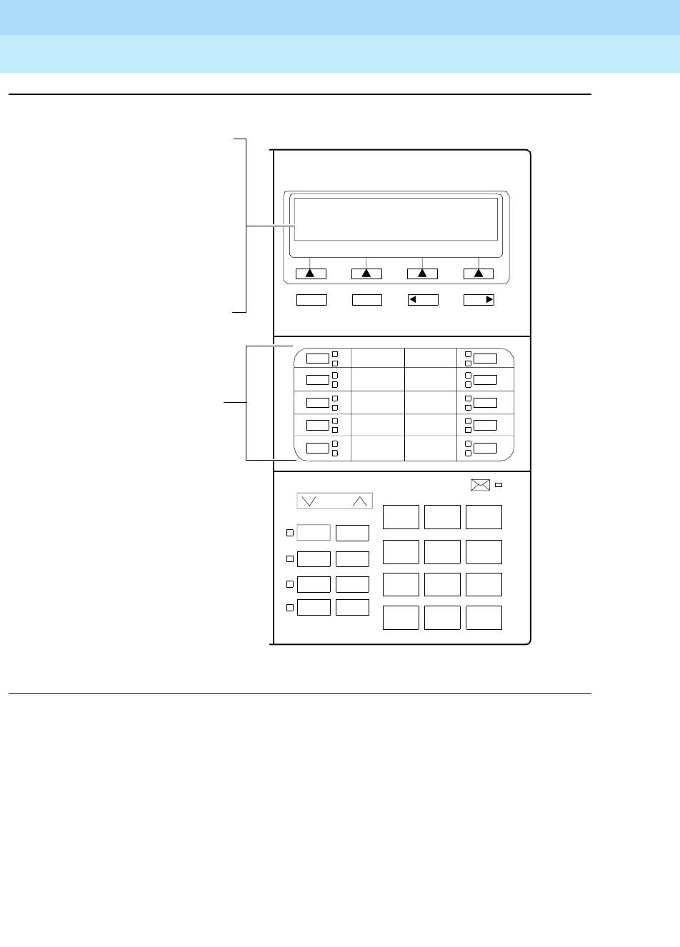
DEFINITYEnterpriseCommunicationsServerandSystem75andSystem85
Terminals and Adjuncts Reference
555-015-201 Issue 11
December 1999
The 8400 Series Voice Terminals
12-47The 8410 Voice Terminal
12
Figure 12-13. Button Numbering for Administering the 8410 Voice Terminal Connected
to a System 75, a DEFINITY G1 or G3, or a DEFINITY ECS
Volume
Ring Transfer
Test Conf
Mute Drop
Speaker Hold
123
456
789
ABC DEF
MNOJKLGHI
PQRS TUV WXYZ
*
O#
NextPrevMenu Exit
If the 8410D is administered
The10call
1
2
3
4
5
8410D
6
7
8
9
10
as a 7405D, administer the
12 softkey features on
“FEATURE BUTTON
ASSIGNMENTS” 2 through
13; administer the Normal
featureonButton#1.
If the 8410D is administered
as itself, administer the
12 softkey features on
“SOFTKEY BUTTON
ASSIGNMENTS”
1 through 12.
appearance/feature
buttons are administered as
“BUTTON ASSIGNMENTS”
1 through 10.
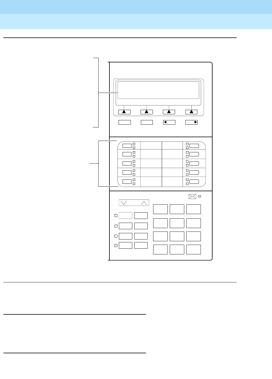
DEFINITYEnterpriseCommunicationsServerandSystem75andSystem85
Terminals and Adjuncts Reference
555-015-201 Issue 11
December 1999
The 8400 Series Voice Terminals
12-48The 8410 Voice Terminal
12
Figure 12-14. Button Numbering for Administering the 8410 Voice Terminal Connected
to a System 85 or a DEFINITY G2
Power Failure Operation
The 8410 voice terminal cannot be used as an emergency station during power
failure transfer conditions.
FCC Registration
The 8410 voice terminal is FCC-registered along with the switch (as a system),
but does not have a separate FCC registration label.
Volume
Ring Transfer
Test Conf
Mute Drop
Speaker Hold
123
456
789
ABC DEF
MNOJKLGHI
PQRS TUV WXYZ
*
O#
NextPrevMenu Exit
If the 8410D is administered
The10call
3
4
5
6
7
8410D
8
9
10
11
12
as a 7405D, administer the
12 softkey features on
“FEATURE BUTTON
ASSIGNMENTS” 14 through
25; administer the Normal
featureonButton#13.
If the 8410D is administered
as itself, administer the
12 softkey features on
“SOFTKEY BUTTON
ASSIGNMENTS”
1 through 12.
appearance/feature
buttons are administered as
“BUTTON ASSIGNMENTS”
3 through 12.

DEFINITYEnterpriseCommunicationsServerandSystem75andSystem85
Terminals and Adjuncts Reference
555-015-201 Issue 11
December 1999
The 8400 Series Voice Terminals
12-49The 8410 Voice Terminal
12
UL and CSA Approval
The 8410 voice terminal has been tested and has met the Underwriters
Laboratories (UL) Standards UL 1459 and has also met the Canadian Standards
Association (CSA) Standards CSA-C22.2 No.225-M90.
Hearing Aid Compatible
The 8410B and 8410D voice terminals are compatible with the inductively coupled
hearing aids prescribed by the FCC.
8410 Equipment PECs and Comcodes
The 8410B and 8410D voice terminals and components can be ordered with
these PECs and Comcodes:
■Basic 8410B (8410D04A) Voice Terminal
Black 8410B Set PEC: 3234-04B
Comcode: 107703696;
White 8410B Set PEC: 3234-04W
Comcode: 107703738
■8410D (8410D03A) Voice Terminal (with built-in display)
Black 8410D Set PEC: 3235-05B
Comcode: 107702870;
White 8410D Set PEC: 3235-05W
Comcode: 107702920
■K2S8 Handset
Comcode: Black=107545584; White=107545568
■Handset cord (9 feet)
Comcode: Black=407632819; White=407632835
■Line cord (7 feet)
Comcode: 103786778
■Line cord (14 feet, silver)
PEC: 2725-07N (COL18)
Comcode: 103786828
■Line cord (25 feet, silver)
PEC: 2725-07S (COL18)
Comcode: 103786802
■Designation Card Cover
PEC: 32309
Comcode: 846320216
■Button Designation Card
Tractor Feed For 25 Sets, 3 Sheets (12 cards per sheet)
PEC: 32310
Comcode: 847161817

DEFINITYEnterpriseCommunicationsServerandSystem75andSystem85
Terminals and Adjuncts Reference
555-015-201 Issue 11
December 1999
The 8400 Series Voice Terminals
12-50The 8410 Voice Terminal
12
Tractor Feed For 100 Sets, 9 Sheets (12 Cards per Sheet)
PEC: 32311
Comcode: 847161916;
Laser Printer Forms (8 1/2”x11”)
67 Sheets (6 Cards per Sheet)
PEC: 32312
Comcode: 847065497
Adjuncts
The following adjuncts can be used with the 8410 voice terminal:
■S101A Speakerphone (no longer orderable)
■S201A Speakerphone
■CS201A Speakerphone
■7400B Plus Data Module
■500A Headset Adapter (and a standard headset; see “Headsets” below)
■K6S2 Amplifier Handset
■Shoulder Rest
Headsets
A list of compatible headsets, consisting of both modular and plug prong base
units and selection of headpieces, appears in “Headset Adapters” in the Adjuncts
section later in this manual.
Additional Documents
The following documents contain additional information relating to the 8410 voice
terminal: (Use the 9 digit number listed after each document to order that book
from the BCS Publications Center for Lucent Technologies.)
■
8403, 8410, and 8434 Voice Terminals Instructions for Installation, Switch
Administration, and Programming the Options
, 555-015-164
■
DEFINITY Communications System Generic 1 and System 75 8410 Voice
Ter m in a l U se r’s Gu i de
, 555-230-763
■
DEFINITY Communications System Generic 1 and 3 and System 75 8410
Quick Reference Guide
, 555-230-764
■
DEFINITY Communications System Generic 2 and System 85 8410 Voice
Ter m in a l U se r’s Gu i de
, 555-104-763
■
DEFINITY Communications System Generic 2 and System 85 8410 Quick
Reference Guide
, 555-104-764
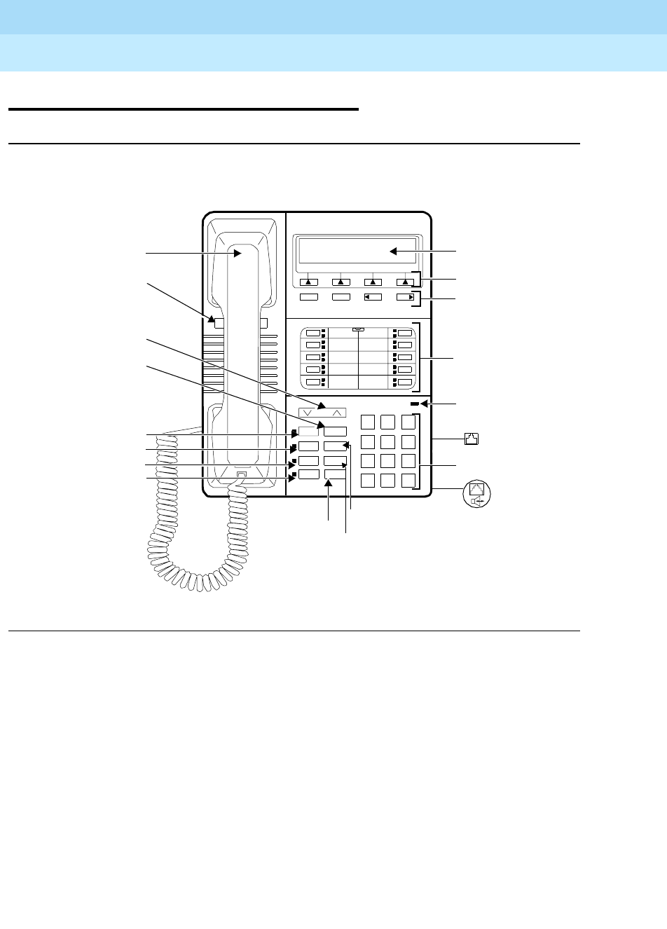
DEFINITYEnterpriseCommunicationsServerandSystem75andSystem85
Terminals and Adjuncts Reference
555-015-201 Issue 11
December 1999
The 8400 Series Voice Terminals
12-51The 8411 Voice Terminal
12
The 8411 Voice Terminal
Figure 12-15. The 8411D Voice Terminal (With Display)
Volume
Shift Transfer
Test Conf
Mute Drop
Speaker Hold
123
456
789
ABC DEF
MNOJKLGHI
PQRS TUV WXYZ
*
O#
Dial Pad
Hold/Ring
Transfer Button
Conference Button
10 Call
Appearance/
Message
4Softkeys
4Display
8411D
NextPrevMenu Exit
Display
Control
Buttons
Ring
Button
Volume Control
Drop Button
Mute Button
Test But ton
Speaker Button
Shift Button
Button
Feature
Buttons
Telephone
Number Card
Message
Handset
Light
LINE
Line Jack
(on back of
terminal)
Speakerphone/
Headset
Adapter Jack
(on back of
terminal)
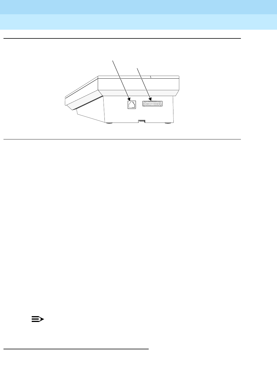
DEFINITYEnterpriseCommunicationsServerandSystem75andSystem85
Terminals and Adjuncts Reference
555-015-201 Issue 11
December 1999
The 8400 Series Voice Terminals
12-52The 8411 Voice Terminal
12
Figure 12-16. The Rear of the 8411 Voice Terminal
The 8411 voice terminal is a multi-appearance digital telephone with 10 call
appearance/feature buttons, four standard fixed feature buttons (CONFERENCE,
DROP, HOLD, and TRANSFER), a blue SHIFT button, a MUTE button, a
SPEAKER button which can access either a 2-way speakerphone or a 1-way,
listen-only speaker, a TEST button, and a Volume control button.
The rear of the 8411 voice terminal has two jacks (see Figure 12-16): The Analog
Adjunct jack can be used for connecting answering machines, fax machines, PC
or laptop data/fax modem cards, data sets or modems, audio teleconferencing
equipment, and TTY machines commonly used by the hearing impaired. The
RS-232-D Jack can be used for connecting the voice terminal to a COM port on
an IBM-compatible personal computer on which you can load PassageWay
Solution software.
There are two varieties of the 8411 voice terminal: the 8411B (8411D02A) is the
basic set, without a display; the 8411D (8411D01A) has a built-in 2-line by
24-character display. Those users who have an 8411D with display can access 12
features with the softkeys and display control buttons. These 12 features can be
used
in addition to
the features on the call appearance/feature buttons.
The 8411 voice terminal can work in both 4-wire and 2-wire environments. For
more information, see “Wiring Information.”
NOTE:
As of September 1, 1998, the 8411B will be discontinued.
Applications
The 8411 voice terminal can be used with the DEFINITY Communications System
Generic 1, Generic 2, and Generic 3, the DEFINITY ECS, System 75, and System
85. This type of voice terminal is especially suitable for managers, executive
secretaries, and other office support personnel who require access to multiple
Analog Adjunct jack
RS-232-D jack

DEFINITYEnterpriseCommunicationsServerandSystem75andSystem85
Terminals and Adjuncts Reference
555-015-201 Issue 11
December 1999
The 8400 Series Voice Terminals
12-53The 8411 Voice Terminal
12
lines for call handling, call coverage, bridging, conferencing, and sophisticated
voice communications. The display set can be used by those who have a need for
calling party display capabilities or who require a large number of voice terminal
features. The jacks on the rear of the set allow connection of a PC for
PassageWay connection and an analog device (see the list of possible analog
adjuncts above).
The 8411 voice terminals can also provide the user with simultaneous voice and
data communications. The 8411 can be connected to a 7400B Plus Data Module
or an 8400B Plus Data Module. With the 8411 voice terminal, PC platform
products can be useful in providing voice capabilities since these screen-based
products can greatly enhance the telephone capabilities of these voice terminals.
Physical Features
Dimensions
NOTE:
The dimensions described here for the 8411 voice terminal are approximate.
Width = 7-3/4 inches
Depth (front to back) = 9-1/2 inches
Height (maximum with handset in place)
The desk-mounted model = 5-1/4 inches
Features
Eight Fixed Feature Buttons
The 8411 has the following eight fixed feature buttons:
■CONFERENCE (labeled CONF) button
■DROP button
■TRANSFER button
■A red HOLD button
■A blue SHIFT button
■MUTE button
■SPEAKER button
■TEST button

DEFINITYEnterpriseCommunicationsServerandSystem75andSystem85
Terminals and Adjuncts Reference
555-015-201 Issue 11
December 1999
The 8400 Series Voice Terminals
12-54The 8411 Voice Terminal
12
The SHIFT Button
The blue SHIFT button on the set can be used with the HOLD button to select
your own personalized ring from among eight available patterns. (The red light
next to the SHIFT button goes on steadily when the button is activated.)
Call Appearance/Feature Buttons
The 8411 voice terminal has 10 call appearance/feature buttons, each equipped
with a red light and a green status light. Usually, at least three of these buttons are
administered as call appearances for the terminal’s primary extension number,
where calls are placed and answered. The rest of the buttons can be used for
more call appearances (including bridged appearances of other stations’
extensions) and features. Buttons administered for features have only their green
status lights active.
Message Light
The red Message light goes on when a message is left for the user. It goes off
when the user retrieves the message or when the message is erased.
Speakerphone
The 8411 voice terminal is equipped with a built-in speakerphone. (The voice
terminal can be optioned for a 1-way, listen-only speaker instead.) The
Speakerphone capability allows a user to engage in a hands-free conversation
with the far-end party. The speakerphone can be turned on or off with the
SPEAKER button; can be muted with the MUTE button, and the volume can be
raised and lowered with the VOLUME “arrow” button.
Speaker (Listen-Only) Feature
Although the 8411 voice terminal is shipped from the factory with the terminal set
for the Speakerphone feature, the 8411 voice terminal can be optioned instead for
a 1-way, listen-only speaker. If this is the case, use the SPEAKER button on the
front of the voice terminal for turning on and off the speaker.
The Speaker (listen-only) capability allows a user to engage in a 1-way
conversation with the far-end. Specifically, the user can only listen to the far-end.
To speak with the far-end, the user must use the handset which turns off the
speaker. The Speaker function may also be disabled.
MUTE Button
The MUTE button is a fixed feature button with a red status light. The MUTE
button turns off the microphone of the built-in speakerphone or the handset so
that a person can converse with another person in the room without the other
party listening in.
DEFINITYEnterpriseCommunicationsServerandSystem75andSystem85
Terminals and Adjuncts Reference
555-015-201 Issue 11
December 1999
The 8400 Series Voice Terminals
12-55The 8411 Voice Terminal
12
VOLUME Control Button
The 8411 voice terminal has a VOLUME “arrow” button on the front of the set.
This button has several functions. When the user is using the speakerphone or the
1-way speaker, the VOLUME button controls the volume of the speaker. When the
user is on a call using the handset, the VOLUME button controls the handset
volume. When the voice terminal is idle, the button controls the volume of the tone
ringer.
When the user sets the volume for the speaker, speakerphone, handset, or the
tone ringer, the display on the 8411D voice terminal shows a “bar array” that
indicates the volume setting.
TEST Button
When the voice terminal is initially powered up, the green light next to the TEST
button flashes if the link with the PBX is not (or not yet) operational. The light
changes to steady green when the voice terminal is able to communicate with the
PBX. After the voice terminal is powered up, you can press the TEST button to
test the lights and the display on your voice terminal.
Display
The display on the 8411D set has two lines with 24 characters on each line. The
display, along with the softkeys and the display control buttons, can be used to
access 12 softkey features (the default softkey features and the alternative softkey
features are listed under “Softkeys”).
Display Control Buttons
These four buttons are labeled ,, , and .
■is used to enter Softkey Mode and access the 12 softkey features.
■is used for exiting a display feature and returning to Normal
(call-handling) Mode.
■and can be used to help you go back and forth through
the feature option screens.
Softkeys
The four buttons located below the display and labeled with arrows correspond to
features listed on the second line of the display screen. (There are four features
on each feature option screen.) The user can access any of the 12 features by
pressing the softkey below the feature abbreviation.
Menu Exit Prev Next
Menu
Exit
Prev Next
DEFINITYEnterpriseCommunicationsServerandSystem75andSystem85
Terminals and Adjuncts Reference
555-015-201 Issue 11
December 1999
The 8400 Series Voice Terminals
12-56The 8411 Voice Terminal
12
Below is a list of the 12 default softkey features assigned to the 8411 and the
order in which they appear.
On 8411D voice terminals (8411 terminals with a display) connected to a
DEFINITY G3V3 or later, the System Manager can choose to administer alternate
features for use with the softkeys. The following table lists some of the alternate
softkey features that can be substituted for the default softkey features listed on
the previous page.
NOTE:
The DEFINITY ECS Release 5 (and later releases) may provide additional
alternate softkey features.
NOTE:
With G3V3 and later switches, the system can download
BLANK
softkey
labels for positions where there are no features administered.
Table 12-16. Default Softkey Features on the 8411D
Abbreviation Feature
First Screen LWC Leave Word Calling
CnLWC Cancel Leave Word Calling
AutCB Automatic Callback
Timer Timer
Second Screen CFrwd*
* On a DEFINITY Generic 2 or on a System 85, this feature is named Call Forward -
Follow Me.
Call Forward
CPark†
† OnaDEFINITYG2andonaSystem85,thereisnoCallParkfeaturethatcanbe
assigned to a feature button. In order to have the Call Park function on a softkey or hard
button, administer the button as an Abbreviated Dial button and program the Call Park
trunk group access code onto it. This button can then be labeled “Call Park.” In addition,
on a DEFINITY G2 or a System 85, the Recall feature must be administered on a
standard feature button.
Call Park
TmDay Time/Date
PCall Priority Calling
Third Screen Prog Abbreviated Dialing Program
Pause Abbreviated Dialing Special Function Pause
Mark Abbreviated Dialing Special Function Mark
Wait Abbreviated Dialing Special Function Wait

DEFINITYEnterpriseCommunicationsServerandSystem75andSystem85
Terminals and Adjuncts Reference
555-015-201 Issue 11
December 1999
The 8400 Series Voice Terminals
12-57The 8411 Voice Terminal
12
Table 12-17. Alternate Softkey Features on the 8411D Connected to a
DEFINITY G3V3 and Later
Abbreviations Feature
AD Abbreviated Dialing buttons (can be multiple AD
buttons)
Cnslt Consult
Count ACD Stroke Count
CPkup Call Pickup
Dir*
* A CALL DISPLAY button should be administered, if access to System Directory is
provided. It is also desirable for a NEXT DISPLAY button to be administered. This
feature is
not
available on a DEFINITY G2 or System 85.
Directory
Excl Manual Exclusion
HFAns†
† This feature is available only on a DEFINITY G3V2 (or later) switches.
Internal Auto Answer
IAuto Intercom Auto
IDial Intercom Dial
Inspt Inspect
Last Last Number Dialed
RngOf Ringer Off
SAC Send All Calls
SFunc Abbreviated Dialed Special Function
Spres Abbreviated Dialing Special Function Suppress
Stats View (ACD) Statistics
Stop Abbreviation Dialing Indefinite Wait or Stop
View‡
‡ This feature is
not
available on a DEFINITY G2 or System 85.
Stored Number

DEFINITYEnterpriseCommunicationsServerandSystem75andSystem85
Terminals and Adjuncts Reference
555-015-201 Issue 11
December 1999
The 8400 Series Voice Terminals
12-58The 8411 Voice Terminal
12
Other Physical Features
Handset
The 8411 voice terminal is equipped with a K-type handset.
Dial pad
The 8411 voice terminal is equipped with a 12-button touch-tone dial pad. The
letters “Q” and “Z” have been added to the appropriate dial pad keys for directory
access, and the “5” button on the dial pad has raised bars for visually-impaired
users.
Jacks
The 8411 voice terminal’s housing has a Line jack located on the back of the
housing, and a Handset cord jack located on the side of the set. There is also a
Speakerphone/headset adapter jack to which the user can connect adjunct
equipment.
The Analog Adjunct jack on the rear of the 8411 voice terminal can be used for
connecting answering machines, fax machines, PC or laptop data/fax modem
cards, data sets or modems, audio teleconferencing equipment, and TTY
machines commonly used by the hearing impaired. The RS-232-D Jack also on
the rear of the voice terminal can be used for connecting the voice terminal to a
COM port on an IBM-compatible personal computer on which you can load
PassageWay Solution software.
Cords
Two cords are supplied with the 8411: a coiled 9-foot handset cord and a 7-foot
line cord.
Optional longer cords are available: a 12-foot handset cord and 14-foot and
25-foot line cords.
Ringing
The 8411 voice terminal has electronic tone ringing with eight possible ringing
patterns that can be selected with the SHIFT button and the HOLD button. The
loudness of the tone ringer can be controlled by the VOLUME “arrow” button. (The
user must NOT be on a speakerphone call. If the user is using the speakerphone,
the VOLUME “arrow” button controls the volume of the speakerphone.)
Mounting Options
The 8411 voice terminal comes equipped with a 2-position desk stand. The 8411
cannot be wall-mounted.
Color Options
The 8411 voice terminal is available in black and in white.

DEFINITYEnterpriseCommunicationsServerandSystem75andSystem85
Terminals and Adjuncts Reference
555-015-201 Issue 11
December 1999
The 8400 Series Voice Terminals
12-59The 8411 Voice Terminal
12
PassageWay and Analog Adjunct Connections
Connecting the 8411 to a Personal Computer for PassageWay
Applications
The RS-232-D jack on the 8411 voice terminal provides the user with a direct
interface between an IBM-compatible personal computer and a DEFINITY switch.
This connection with the PC allows access to Lucent Technologies PassageWay
Solution applications.
For information about installing and setting up the PassageWay software, see the
PassageWay
-Direct Connection Solution For DEFINITY Communications System
8411 Voice Terminal User’s Guide, 555-201-115.
NOTE:
In order for the 8411 voice terminal to operate, the voice terminal must have
auxiliary power, either locally using an 1151A1 power supply or 1151A2
power supply with Battery Holdover or remotely using an 1145B1 closet
supply. Also, before the PassageWay connection can be set up, the exact
COM port number (that is, COM1, COM2, COM3, or COM4) to which the
8411 voice terminal is being connected must be identified.
Connecting an Analog Adjunct to the 8411 Voice Terminal
Through the Analog Adjunct RJ11C jack on the rear of the set, the 8411 voice
terminal provides connection with Analog Adjuncts such as answering machines,
fax machines, PC or laptop data/fax modem cards, data sets or modems, audio
teleconferencing equipment, and TTY machines commonly used by the hearing
impaired. On System 75, System 85, and DEFINITY G1 and G2 and DEFINITY
G3 prior to G3V4, Issue 3, the analog equipment shares the telephone line (or
I1-Channel) with the voice terminal. Therefore, while the telephone is being used,
you
cannot
use the Analog Adjunct at the same time, or vice versa. Beginning with
the DEFINITY G3V4, Issue 3 (and all later releases), the 8411 and Analog
Adjunct can use separate telephone lines (the I1-Channel and I2-Channel) and
thus the voice terminal and the Analog Adjunct can be used simultaneously.
The PassageWay Button (Button #9) and the Analog Adjunct Button
(Button #10)
The system manager may choose to option Button #9 on the 8411 voice terminal,
the next-to-last button in the second column, (see Figure 12-17 for the location of
this button) so that the red and green lights next to the button provide
PassageWay status information. (See “PassageWay Status Indications” later in
this section on the 8411.) If Button #9 is optioned in this manner, it is then disabled
and CANNOT be used as a call appearance button or feature button.
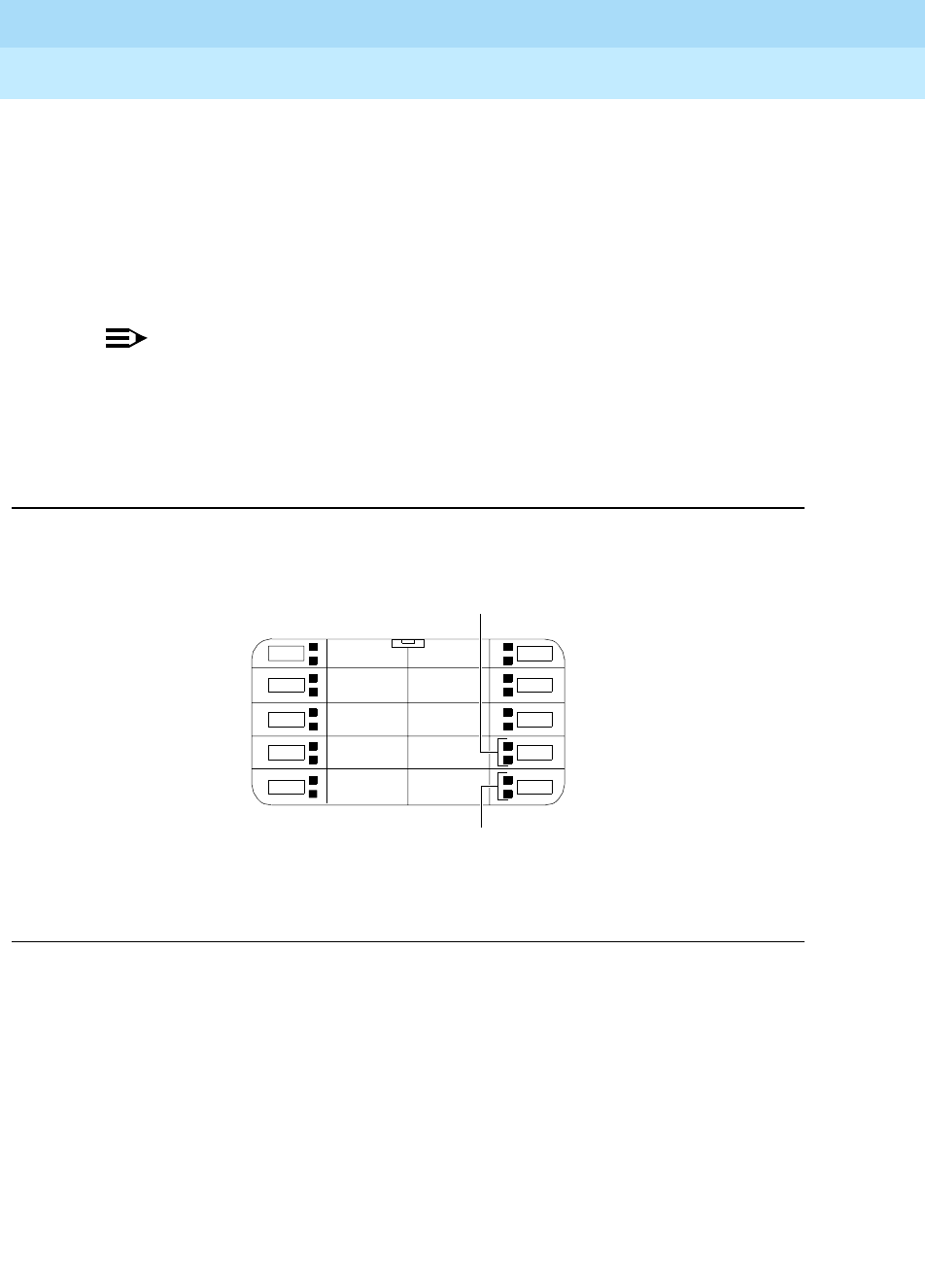
DEFINITYEnterpriseCommunicationsServerandSystem75andSystem85
Terminals and Adjuncts Reference
555-015-201 Issue 11
December 1999
The 8400 Series Voice Terminals
12-60The 8411 Voice Terminal
12
The system manager may also choose to option Button #10 (again, see
Figure 12-17 below for its location) so that its adjacent red and green lights
provide Analog Adjunct status information. (See “Analog Adjunct Status
Indications” later in this section on the 8411.) If Button #10 is optioned in this way,
the button’s function changes from a call appearance/feature button to a local
button that can be used to send a disconnect signal to the analog adjunct. (See
“Sharing the 8411 Telephone Line with the Analog Adjunct” later in this section on
the 8411.)
NOTE:
When the status indication feature is optioned, Button #9 is always used to
monitor the PassageWay connection, and Button #10 is always used to
monitor the Analog Adjunct. No other buttons on the 8411 can be used for
these purposes. If these two buttons are not used for PassageWay and an
Analog Adjunct, they can be used for switch features.
Figure 12-17. The Location of Buttons #9 and #10 on the 8411
1
2
3
4
5
6
7
8
9
10
These lights are used for
PassageWay status
These lights are used for
Analog Adjunct status
DEFINITYEnterpriseCommunicationsServerandSystem75andSystem85
Terminals and Adjuncts Reference
555-015-201 Issue 11
December 1999
The 8400 Series Voice Terminals
12-61The 8411 Voice Terminal
12
PassageWay Status Indications
The 8411 provides the following status indications, next to Button #9 for the
PassageWay connection:
Analog Adjunct Status Indications
The 8411 uses the GREEN and the RED lights next to Button #10 to provide the
following status indications for the Analog Adjunct connection.
NOTE:
The flash indication has priority over the on-hook and off-hook indications
listed immediately above.
Table 12-18. PassageWay Status Indications on the 8411 Voice Terminal
PassageWay Status Green light Red light
AT Command Mode Off On
PassageWay Mode On Off
DCP Looparound Flash*
*A
Flash
is a repeating pattern of 500 ms ON and 500 ms OFF.
Flash
Switch Link Down Wink†
†A
Wink
is a repeating pattern of 750 ms ON and 250 ms OFF.
Wink
EIA Out-of-Sync Flash Off
Program Mode On Flash
Table 12-19. Analog Adjunct Status Indications on the 8411 Voice Terminal
Analog Adjunct Status Green Light Red Light
The Analog Adjunct is off-hook. On
The Analog Adjunct is on-hook and idle. Off
The voice terminal is sending a Flash
ringing signal to the Analog Adjunct. Flash
The Analog Adjunct is using the
telephone line. On
The 8411 voice terminal is using the
telephone line (that is, the Analog Adjunct
is NOT using the I-Channel).
Off

DEFINITYEnterpriseCommunicationsServerandSystem75andSystem85
Terminals and Adjuncts Reference
555-015-201 Issue 11
December 1999
The 8400 Series Voice Terminals
12-62The 8411 Voice Terminal
12
NOTE:
When the 8411 is programmed for the Analog Adjunct to use a separate
telephone line (that is, the I2-Channel), the red light is always on.
Sharing the 8411 Telephone Line with the Analog Adjunct
When your 8411 voice terminal has not been assigned a separate telephone
number for your analog adjunct, that is, the telephone line must be shared
between your voice terminal and the analog adjunct connected to the Analog
Adjunct jack, you CANNOT use your 8411 and the analog adjunct at the same
time. If you desire to use your 8411 (the handset, the built-in speakerphone, or
any equipment connected to the Speakerphone/Headset jack) while the analog
adjunct is using the line, you must first disconnect from the analog adjunct call.
You may disconnect from the analog adjunct call manually using a button on the
analog adjunct or use a PC command if the analog adjunct is connected to the
PC. Button #10 can also be used to disconnect the call on the analog adjunct if
that button has been enabled for the disconnect function.
In addition to the manual and Button #10 methods for disconnecting from the
analog adjunct call, going off-hook and pressing the appropriate call appearance
button will also cause the line to be switched to the voice terminal (handset,
speakerphone, or any equipment connected to the Speakerphone/ Headset jack)
and a disconnect signal will be sent to the analog adjunct. This method allows you
to automatically disconnect the analog adjunct to:
■Answer an incoming call on another call appearance
■Originate a call on an idle call appearance
■Interrupt the analog adjunct and use the active call appearance
NOTE:
This feature requires the 8411 to use the first three call appearance/feature
buttons (the top three buttons in the first column) as call appearance
buttons. If there are more than three call appearance buttons administered,
the feature will still work with these (top) three buttons, but NOT with the
additional call appearance buttons.
For incoming calls, the device that answers first (that is, the 8411 handset, 8411
built-in speakerphone, any equipment connected to the Speakerphone/ Headset
jack on the 8411, or the analog adjunct connected to the 8411 Analog Adjunct
jack) gets control of the call. Note that not all incoming calls will cause a ringing
signal to be sent to the analog adjunct. A ringing signal will be sent only if all call
appearances are idle and the incoming call is either an inside call, a DID call, or a
Priority call.
DEFINITYEnterpriseCommunicationsServerandSystem75andSystem85
Terminals and Adjuncts Reference
555-015-201 Issue 11
December 1999
The 8400 Series Voice Terminals
12-63The 8411 Voice Terminal
12
Wiring Information
The 8411 voice terminal works in both 4-wire and 2-wire DCP configurations. The
table below describes the pins on an 8400-Series voice terminal LINE jack.
NOTE:
Regardless of which configuration is in use, ALL wiring between the PBX
and the terminal MUST consist of twisted-pairs, including the modular line
cord. The line cord must be a D8W, which consists of 4 twisted-pairs, or a
Lucent Technologies-approved equivalent.
Twisted-pair wiring is used to make lines less sensitive to crosstalk.
Therefore, failure to use twisted pair wiring may result in less-than-optimum
performance of the terminal and may also contribute to problems with the
line.
An 8-wire modular cord MUST be used for all 4-wire and any 2-wire
installations requiring auxiliary power.
NOTE:
You do NOT need to change any settings on the voice terminal for 2-wire or
4-wire installations. The voice terminal is able to detect whether it is in a
2-wire or a 4-wire configuration.
For 2-wire operation, if you need to plug the voice terminal into a 4-pin or
6-pin wall jack, instead of a standard 8-pin modular jack, refer to the “Line
Interface” table to insure that the wires from the 4-pin or 6-pin wall jack are
connected to the correct pins on the terminal “LINE” jack.
Table 12-20. The Pins on an 8400-Series Voice Terminal LINE Jack
Line Interface
Pin Pair Name Description
1 2 OD1 4-Wire Output
2 2 OD2 4-Wire Output
3 3 ID1 4-Wire Input
41U-T 2-Wire(Tip)
5 1 U-R 2-Wire (Ring)
6 3 ID2 4-Wire Input
7 4 P1- Adjunct Power -48V
8 4 P2+ Adjunct Power Common

DEFINITYEnterpriseCommunicationsServerandSystem75andSystem85
Terminals and Adjuncts Reference
555-015-201 Issue 11
December 1999
The 8400 Series Voice Terminals
12-64The 8411 Voice Terminal
12
In order for the terminal to function properly in either 2-wire or 4-wire
installations, there must be NO INTERCONNECTIONS between the wire
pairs used for 2-wire and 4-wire operations. Bridging or paralleling of these
pairs can result in damage to the terminal or can cause the PBX circuit pack
to remove power to the terminal.
REMOVE ALL CONNECTIONS BETWEEN PAIRS BEFORE
CONNECTING THE TERMINAL.
4-WIRE installations MUST ONLY have PBX connections on pair 2 and pair
3 and, if necessary, auxiliary power must be connected to pair 4.
2-WIRE installations MUST ONLY have PBX connections on pair 1 and, if
necessary, auxiliary power must be connected to pair 4.
Distance Limitations
The following circuit packs can be used with all of the 8400-Series sets.
In 4-wire operation, the voice terminal must be within 5,000 feet of the PBX using
22-gauge or 24-gauge wire, and within 4,000 feet of the PBX using 26-gauge wire.
In 2-wire operation, the voice terminal must be within 5,500 feet of the PBX using
22-gauge wire, within 3,500 feet of the PBX using 24-gauge wire, and within 2,200
feet of the PBX using 26-gauge wire.
Power Requirements
In order for the 8411 voice terminal to operate, the voice terminal must have
auxiliary power, either locally using an 1151A1 power supply or 1151A2 power
supply with Battery Holdover or remotely using an 1145B1 closet supply. Refer to
the Adjunct Power section earlier in this manual for information on these power
supplies.
Table 12-21. Circuit Packs Used with the 8400-Series Voice Terminals
Circuit Pack 2/4-Wire Will support these switches
TN2181 - 16-port 2-wire G3V3, G3V2
TN754b - 8-port 4-wire All switches except System 85
TN754 - 8-port 4-wire All switches except System 85
TN413 - 8-port 4-wire International System 75
SN 270 and SN
270B - 4-port 4-wire System 85 R2V2 - R2V4
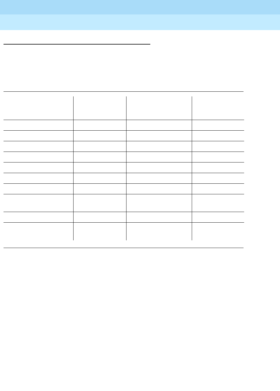
DEFINITYEnterpriseCommunicationsServerandSystem75andSystem85
Terminals and Adjuncts Reference
555-015-201 Issue 11
December 1999
The 8400 Series Voice Terminals
12-65The 8411 Voice Terminal
12
Switch Administration
Aliasing
Use the following table for administering the 8411B (the basic) voice terminal:
Table 12-22. Administering the 8411B Voice Terminal
If you have this System and this Release
(which can support
this type of
operation)
Administer the
8411B as a
System 75 R1V1 — R1V3 4-wire only 7403D
System 85 R2V2 — R2V4 4-wire only 7403D
International System 75 IR1V4, etc. 4-wire only 7403D
DEFINITY G1 4-wire only 7403D
Global DEFINITY ’91 4-wire only 7410D
DEFINITY G2V1 4-wire only 7410D
DEFINITY G2V2 4-wire only 7410D
DEFINITY G3i, G3r,
G3s, G3vs 4-wire only 7410D
DEFINITY G3V2 2- or 4-wire 7410D
DEFINITY G3V3 and
later 2- or 4-wire 8410B
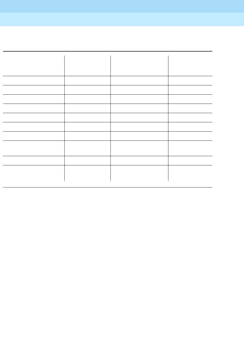
DEFINITYEnterpriseCommunicationsServerandSystem75andSystem85
Terminals and Adjuncts Reference
555-015-201 Issue 11
December 1999
The 8400 Series Voice Terminals
12-66The 8411 Voice Terminal
12
Use this table for administering the 8411D (with display) voice terminal:
Button Numbering
The following button diagrams of the 8411 voice terminal will help you administer
both of these voice terminals connected to a System 75, a DEFINITY G1 and G3,
or a DEFINITY ECS, and to a System 85 or a DEFINITY G2.
Figure 12-18 shows button numbering for the 8411 connected to a
System 75, DEFINITY G1 and G3, or a DEFINITY ECS. Figure 12-19 shows
button numbering for the 8411 connected to a System 85 or DEFINITY G2.
If you need more information, refer to
DEFINITY Communications System
Generic 3 Implementation
, 555-230-653, and
DEFINITY Communications System
Generic 2 Administration of Features and Hardware
, 555-104-507.
Table 12-23. Administering the 8411D Voice Terminal
If you have this System and this Release
(which can support
this type of
operation)
Administer the
8411D as a
System 75 R1V1 — R1V3 4-wire only 7405D+D
System 85 R2V2 — R2V4 4-wire only 7405D+D
International System 75 IR1V4, etc. 4-wire only 7405D+D
DEFINITY G1 R1V4 4-wire only 7405D+D
Global DEFINITY ’91 4-wire only 7405D+D
DEFINITY G2V1 4-wire only 7405D+D
DEFINITY G2V2 4-wire only 7405D+D
DEFINITY G3i, G3r,
G3s, G3vs 4-wire only 7405D+D
DEFINITY G3V2 2- or 4-wire 7405D+D
DEFINITY G3V3 and
later 2- or 4-wire 8410D
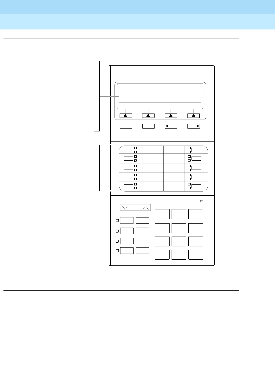
DEFINITYEnterpriseCommunicationsServerandSystem75andSystem85
Terminals and Adjuncts Reference
555-015-201 Issue 11
December 1999
The 8400 Series Voice Terminals
12-67The 8411 Voice Terminal
12
Figure 12-18. Button Numbering for Administering the 8411 Voice Terminal Connected
to a System 75, a DEFINITY G1 or G3, or a DEFINITY ECS
Volume
Shift Transfer
Test Conf
Mute Drop
Speaker Hold
123
456
789
ABC DEF
MNOJKLGHI
PQRS TUV WXYZ
*
O#
NextPrevMenu Exit
If the 8411D is administered
The10call
1
2
3
4
5
8411D
6
7
8
9
10
Message
Ring
as a 7405D, administer the
12 softkey features on
“FEATURE BUTTON
ASSIGNMENTS” 2 through
13; administer the Normal
featureonButton#1.
If the 8411D is administered
as an 8410D, administer the
12 softkey features on
“SOFTKEY BUTTON
ASSIGNMENTS”
1 through 12.
appearance/feature
buttons are administered as
“BUTTON ASSIGNMENTS”
1 through 10.
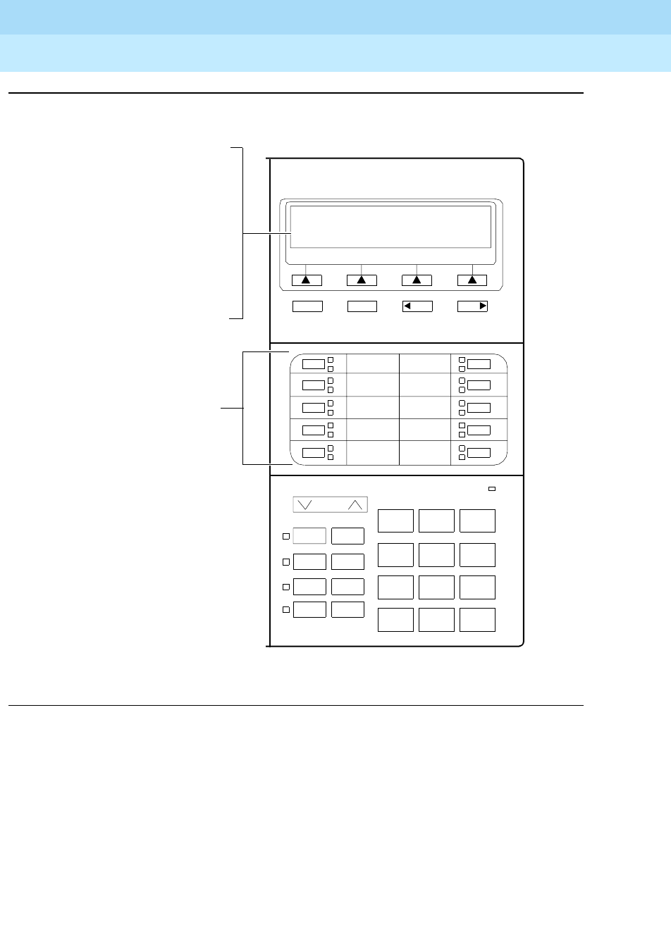
DEFINITYEnterpriseCommunicationsServerandSystem75andSystem85
Terminals and Adjuncts Reference
555-015-201 Issue 11
December 1999
The 8400 Series Voice Terminals
12-68The 8411 Voice Terminal
12
Figure 12-19. Button Numbering for Administering the 8411 Voice Terminal Connected
to a System 85 or a DEFINITY G2
Administering the Analog Adjunct
As noted in Table 12-22 and 12-23, the 8411D can be administered as itself
ONLY IF it is connected to a DEFINITY G3V4, Issue 3 (or later) switch. In Native
Mode the voice terminal is administered through a digital line circuit card with a
line number (with the usual three call appearances) assigned to the I-1 Channel.
A second line number can be administered through the same digital line card on
the I-2 Channel, but this line number can only be used for analog adjuncts
connected to the Analog Adjunct jack on the 8411. This Analog Adjunct is
assigned a private number, but can be used only for placing or terminating a call.
Volume
Shift Transfer
Test Conf
Mute Drop
Speaker Hold
123
456
789
ABC DEF
MNOJKLGHI
PQRS TUV WXYZ
*
O#
NextPrevMenu Exit
If the 8411D is administered
The10call
3
4
5
6
7
8411D
8
9
10
11
12
Message
Ring
as a 7405D, administer the
12 softkey features on
“FEATURE BUTTON
ASSIGNMENTS” 14 through
25; administer the Normal
featureonButton#13.
If the 8411D is administered
as an 8410D, administer the
12 softkey features on
“SOFTKEY BUTTON
ASSIGNMENTS”
1 through 12.
appearance/feature
buttons are administered as
“BUTTON ASSIGNMENTS”
3 through 12.

DEFINITYEnterpriseCommunicationsServerandSystem75andSystem85
Terminals and Adjuncts Reference
555-015-201 Issue 11
December 1999
The 8400 Series Voice Terminals
12-69The 8411 Voice Terminal
12
It cannot be used for any other analog functions such as transferring a call or
setting up a conference call. If a second line on the 8411 is administered on the
I-2-Channel (for analog equipment) on the 8411, type “analog” in the Data Option
field on the administration screen.
Power Failure Operation
The 8411 voice terminal cannot be used as an emergency station during power
failure transfer conditions.
FCC Registration
The 8411 voice terminal is FCC-registered along with the switch (as a system),
but does not have a separate FCC registration label.
UL and CSA Approval
The 8411 voice terminal has been tested and has met the Underwriters
Laboratories (UL) Standards UL 1459 and has also met the Canadian Standards
Association (CSA) Standards CSA-C22.2 No.225-M90.
Hearing Aid Compatible
The 8411B and 8411D voice terminals are compatible with the inductively coupled
hearing aids prescribed by the FCC.
8411 Equipment PECs and Comcodes
The 8411B and 8411D voice terminals and components can be ordered with
these PECs and Comcodes:
■Basic 8411B (8411D02A) Voice Terminal
Black 8411B Set PEC: 3234-TRB with power supply PEC: 3234-PTB
Comcode: 107526535;
White 8411B Set PEC: 3234-TRW with power supply PEC: 3234-PTW
Comcode: 107526543
■8411D (8411D01A) Voice Terminal (with built-in display)
Black 8411D Set PEC: 3235-TRB with power supply PEC: 3235-PTB
Comcode: 107526501;
White 8411D Set PEC: 3235-PTW with power supply PEC: 3234-PTW
Comcode: 107526519
■K2S6 Handset
Comcode: Black=107180549; White=107181471
■K6S2-003 (Black) Amplifier Handset
Comcode: 105581896

DEFINITYEnterpriseCommunicationsServerandSystem75andSystem85
Terminals and Adjuncts Reference
555-015-201 Issue 11
December 1999
The 8400 Series Voice Terminals
12-70The 8411 Voice Terminal
12
■Handset cord (9 feet)
Comcode: Black=105635429; White=105701809
■Line cord (7 feet)
Comcode: 103786778
■Line cord (14 feet, silver)
PEC: 2725-07N (COL18)
Comcode: 103786828
■Line cord (25 feet, silver)
PEC: 2725-07S (COL18)
Comcode: 103786802
■Designation Card Cover
PEC: 32309
Comcode: 846320216
■Button Designation Card
Tractor Feed For 36 Sets, 3 Sheets (12 cards per sheet)
PEC: 32310
Comcode: 847161817;
Tractor Feed For 108 Sets, 9 Sheets (12 cards per sheet)
PEC: 32311
Comcode: 847161916;
Laser Printer Forms (8 1/2”x11”)
67 Sheets (6 cards per sheet)
PEC: 32312
Comcode: 847065497
■PassageWay connection software, documentation, and cables
PEC: 8302-800
Comcode: 407504646
Adjuncts
The following adjuncts can be used with the 8411 voice terminal:
■S101A Speakerphone (no longer orderable)
■S201A Speakerphone
■CS201A Speakerphone
■7400B Plus Data Module
■8400B Plus Data Module
■500A Headset Adapter (and a standard headset;
see “Headsets” below)
■K6S2 Amplifier Handset
■Shoulder Rest

DEFINITYEnterpriseCommunicationsServerandSystem75andSystem85
Terminals and Adjuncts Reference
555-015-201 Issue 11
December 1999
The 8400 Series Voice Terminals
12-71The 8411 Voice Terminal
12
Headsets
A list of compatible headsets, consisting of both modular and plug prong base
units and selection of headpieces, appears in “Headset Adapters” in the Adjuncts
section later in this manual.
Additional Documents
The following documents contain additional information relating to the 8411 voice
terminal: (Use the 9 digit number listed after each document to order that book
from the BCS Publications Center for Lucent Technologies.)
■
The 8400-Series Voice Terminals Instructions for Installation, Switch
Administration, and Programming the Options
, 555-015-725
■
DEFINITY Communications System Generic 1 and System 75 8411 Voice
Ter m in a l U se r’s Gu i de
, 555-230-872
■
DEFINITY Communications System Generic 1 and 3 and System 75 8411
Quick Reference Guide
, 555-230-873
■
DEFINITY Communications System Generic 2 and System 85 8411 Voice
Ter m in a l U se r’s Gu i de
, 555-104-769
■
DEFINITY Communications System Generic 2 and System 85 8411 Quick
Reference Guide
, 555-104-770
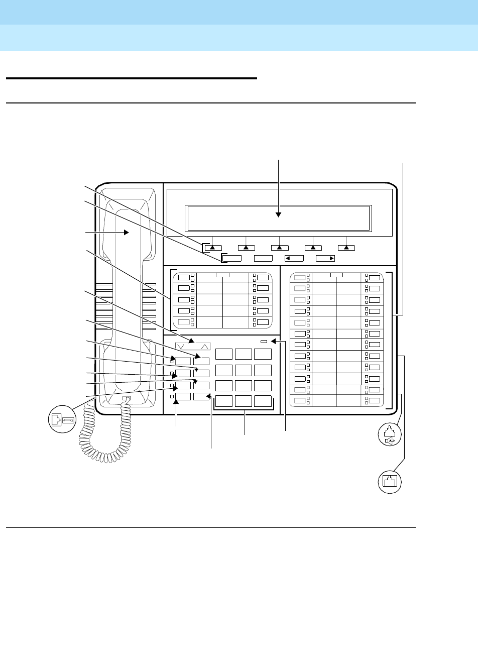
DEFINITYEnterpriseCommunicationsServerandSystem75andSystem85
Terminals and Adjuncts Reference
555-015-201 Issue 11
December 1999
The 8400 Series Voice Terminals
12-72The 8434 and 8434DX Voice Terminals
12
The 8434 and 8434DX Voice Terminals
Figure 12-20. The 8434 Voice Terminal
Headset
Control
Volume
Shift Transfer
Test Conf
Mute Drop
Speaker Hold
Reset Spkr
123
456
789
ABC DEF
MNOJKLGHI
PQRS TUV WXYZ
*
O#
Dial
Handset
Hold/
Transfer Button
Conference Button
Shift Button
24 Call
Message
Test Button
Mute Button
Speaker/
4 Softkeys
4 Display
Display
LINE
Handset Jack
Line Jack
Speakerphone/
Ring
Drop Button
Volume
8434
NextPrevExit
Message
10 Call
Buttons
Control
Button
Reset
Speaker
Appearance/
Feature Buttons
Appearance/
Feature
Buttons
Button Adapter Jack
(on back of
terminal)
(on back
of terminal)
(on back of
voice terminal)
Light
Menu
Button
Ring
Pad
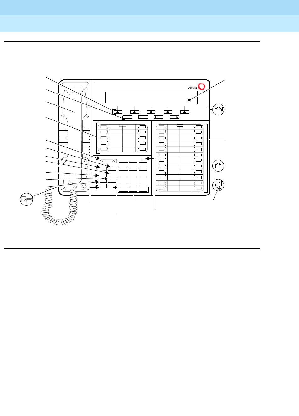
DEFINITYEnterpriseCommunicationsServerandSystem75andSystem85
Terminals and Adjuncts Reference
555-015-201 Issue 11
December 1999
The 8400 Series Voice Terminals
12-73The 8434 and 8434DX Voice Terminals
12
Figure 12-21. One Version of the 8434DX Voice Terminal
Vol ume
Shift Transfer
Test Conf
Mute Drop
Speaker Hold
Reset Spkr
123
456
789
ABC DEF
MNOJKLGHI
PQRS TUV WXYZ
*
O#
Dial Pad
Hold/Ring
24 Call
Message
Speaker/
Display
Handset Jack
Line Jack
Speakerphone/
Ring
NextPrevExit
Expansion
Message
LINE
EX MOD
Reset
Speaker
Button
(on back of
terminal)
Headset Adapter
Jack (on back
(on back
of voice
terminal)
Appearance/
Feature
Buttons
Module Jack
(on back of
of voice
Menu
terminal)
Handset
Transfer Button
Conference
Shift Button
Test Button
Mute Button
4 Softkeys
4Display
Drop Button
Volume Control
10 Call
Button
Control Buttons
Appearance
Feature Buttons
Button
of terminal)
Light
Button
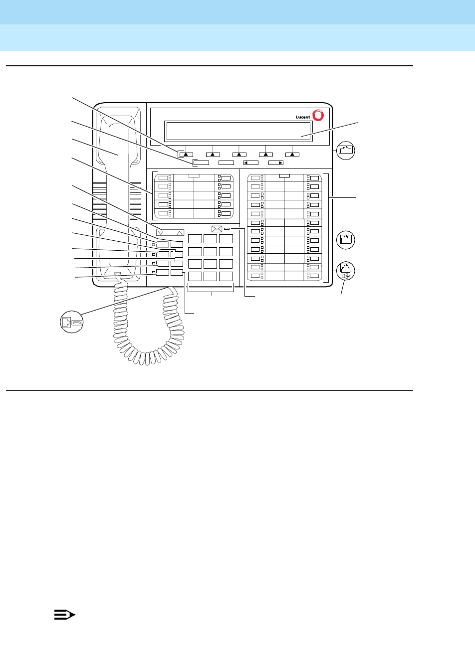
DEFINITYEnterpriseCommunicationsServerandSystem75andSystem85
Terminals and Adjuncts Reference
555-015-201 Issue 11
December 1999
The 8400 Series Voice Terminals
12-74The 8434 and 8434DX Voice Terminals
12
Figure 12-22. Another Version of the 8434DX Voice Terminal
The basic 8434 (8434D01A) and the enhanced 8434DX (8434D02A) voice
terminals are multi-appearance digital voice terminals which offer 34 call
appearance/feature buttons, each with a red light and a green status light, four
standard fixed feature buttons (CONFERENCE, DROP, HOLD, and TRANSFER),
a MUTE button, a SPEAKER button which accesses either a 2-way speakerphone
or a 1-way listen-only speaker, a TEST button, a SHIFT button (some 8434DX
voice terminals will have a RING button instead), a red Message light,
personalized ringing, a built-in speakerphone with a reset option, and a built-in
2-line by 40-character VFD display. The 8434 and 8434DX also have five softkeys
and four display control buttons which allow the user to access 15 features. These
softkey features can be used
in addition to
the features on the call
appearance/feature buttons.
The 8434 and 8434DX voice terminals can be used in both a 4-wire and a 2-wire
environment. For more information, see “Wiring Information.”
NOTE:
In order to use the display on the 8434 or 8434DX voice terminal and to use
an 801A expansion module connected to the 8434DX, you must connect an
Handset jack
Volume
Ring Transfer
Test Con f
Mute Drop
Speaker Hold
123
456
789
ABC DEF
MNOJKLGHI
PQRS TUV WXYZ
*
O#
Dial pad
24 Call
Message
Display
Line jack
Speakerphone/headset
NextPrevMenu Exit
Expansion
LINE
EX MOD
adapter jack (on back of
voice terminal)
(on back
of voice
terminal)
appearance/
feature
buttons
module jack
(on back
of voice
terminal)
Hold button
light
Handset
Transfer button
Conference
Ring button
Test button
Mute button
Speaker button
Softkeys
Display control
Drop button
Volume control
10 Call appearance/
button
buttons
feature buttons
button

DEFINITYEnterpriseCommunicationsServerandSystem75andSystem85
Terminals and Adjuncts Reference
555-015-201 Issue 11
December 1999
The 8400 Series Voice Terminals
12-75The 8434 and 8434DX Voice Terminals
12
auxiliary power supply to the voice terminal. Recommended are an 1151A1
local power supply or an 1151A2 power supply with Battery Holdover.
The 801A Expansion Module can be connected to the 8434DX voice terminal to
provide 24 additional call appearance/feature buttons. The 801A can be used
ONLY with the 8434DX voice terminal and the terminal must be connected to a
DEFINITY G3V3.3 (or later release). For more information about this module, see
the section on the 801A Expansion Module behind the tab labeled Adjuncts.
NOTE:
The basic 8434 (8434D01A) voice terminal is no longer manufactured.
Applications
The 8434 and 8434DX voice terminals can be used with the DEFINITY
Communications System Generic 1, Generic 2, or Generic 3, the DEFINITY ECS,
System 75, or System 85. These terminals are appropriate terminals for users
who handle numerous calls and who need button access to a wide variety of
features. For example, the 8434 and 8434DX voice terminals, with their large
number of administrable buttons, can use the Abbreviated Dialing feature for
reaching many frequently called parties. The buttons of the 8434 and 8434DX
voice terminals can also be assigned for bridging calls at other stations. Typical
users are secretaries, managers, salespeople, buyers, answering groups, and call
covering positions.
The 8434 and 8434DX voice terminals can also provide the user with
simultaneous voice and data communications. The 8434 and 8434DX can be
connected to a 7400B Plus Data Module in a 4-wire environment, or to an 8400B
Plus Data Module in a 2-wire environment. With the 8434 and 8434DX voice
terminals, PC platform products can be useful in providing voice capabilities since
these screen-based products can greatly enhance the telephone capabilities of
these voice terminals.
Physical Description
Dimensions
NOTE:
The dimensions given here for the 8434 and 8434DX voice terminals are
approximate.
Width = 12.5 inches
Depth (front to back) = 10.25 inches
Height (maximum with handset in place) = 5.6 inches

DEFINITYEnterpriseCommunicationsServerandSystem75andSystem85
Terminals and Adjuncts Reference
555-015-201 Issue 11
December 1999
The 8400 Series Voice Terminals
12-76The 8434 and 8434DX Voice Terminals
12
Features
Eight Fixed Feature Buttons
■CONFERENCE (labeled CONF) button
■DROP button
■TRANSFER button
■A red HOLD button
■Either a blue SHIFT button or a RING button
■MUTE button
■SPEAKER button
■TEST button
The SHIFT Button
All 8434 voice terminals have a blue SHIFT button. Some 8434DX voice terminals
have a blue SHIFT button; others have a RING button. (See the description
below.) The SHIFT button can be used in two different ways: (The red light next to
the SHIFT button goes on steadily when the button is activated.)
■Used with the HOLD button to select your own personalized ringing
patterns from among eight available patterns
■Used with the SPEAKER button to perform an acoustic test of the
environment and adjust the speakerphone to the surrounding acoustic
environment for optimal performance
The RING Button
On other 8434DX voice terminals, the user can press the RING button in order to
select a personalized ringing pattern for the voice terminal. There are eight ringing
patterns from which to choose.
Call Appearance/Feature Buttons
The 8434 and 8434DX voice terminals have 34 call appearance/feature buttons,
each equipped with a red light and a green status light. Usually, at least three of
these buttons are administered as call appearances for the terminal’s primary
extension number, where calls are placed and answered. The rest of the buttons
can be used for more call appearances (including bridged appearances of other
stations’ extensions) and features. Buttons administered for features have only
their green status lights active.
Message Light
The red Message light goes on when a message is left for the voice terminal user.
The light goes off when the user retrieves the message or when the message is
erased. This light is labeled either
Message
or .

DEFINITYEnterpriseCommunicationsServerandSystem75andSystem85
Terminals and Adjuncts Reference
555-015-201 Issue 11
December 1999
The 8400 Series Voice Terminals
12-77The 8434 and 8434DX Voice Terminals
12
Speakerphone (Listen and Speak) Feature
The 8434 and 8434DX voice terminals are equipped with a built-in speakerphone.
The Speakerphone capability allows a user to engage in a hands-free 2-way
conversation with the far-end party. The speakerphone can be turned off or on
with the SPEAKER button, can be muted with the MUTE button, and the volume
can be controlled with the VOLUME “arrow” button.
If the voice terminal has a SHIFT button and
Rest Spkr
appears below the
SPEAKER button, the user can access the Reset Speakerphone feature to adjust
the speakerphone for optimal performance.
NOTE:
If there is not a SHIFT button and Reset Spkr does NOT appear under the
SPEAKER button, the voice terminal will adjust to the surrounding
environment by itself. The user does not need to do anything manually.
By pressing the SHIFT button and then the SPEAKER button (if the voice terminal
is set for the Speakerphone feature), the user hears a set of tones as the
speakerphone performs an acoustic test of the environment. When the tones
stop, the speakerphone has finished adjusting itself and is ready for use. The user
should reset the speakerphone whenever the voice terminal is moved to another
place (even in the same room), whenever the red light next to the SPEAKER
button is fluttering, and in the unlikely event that the speakerphone is making a
squealing sound (in this last case, tones will not be heard during a call).
Speaker (Listen-only) Feature
Although the 8434 and 8434DX voice terminals are shipped from the factory with
the terminal set for the Speakerphone feature, the 8434 and 8434DX voice
terminals can be optioned instead for a 1-way, listen-only speaker. If this is the
case, use the SPEAKER button on the front of the voice terminal for turning on
and off the speaker.
The Speaker (listen-only) capability allows a user to engage in a 1-way
conversation with the far-end. Specifically, the user can only listen to the far-end.
To speak with the far-end, the user must use the handset which turns off the
speaker. The Speaker function may also be disabled.
MUTE Button
The MUTE button disables the transmitter of the speakerphone or the handset
depending on which is activated at that time. A red light next to the MUTE button
goes on when the Mute feature is activated.
VOLUME Control Button
The 8434 and 8434DX voice terminals have a VOLUME “arrow” button. This
button has several functions. When the user is on a call using the speaker or
speakerphone, the VOLUME button controls the volume of the speaker or
DEFINITYEnterpriseCommunicationsServerandSystem75andSystem85
Terminals and Adjuncts Reference
555-015-201 Issue 11
December 1999
The 8400 Series Voice Terminals
12-78The 8434 and 8434DX Voice Terminals
12
speakerphone, whichever is being used. When the user is on a call using the
handset, the VOLUME button controls the handset volume. When the voice
terminal is idle, the VOLUME control button adjusts the tone ringer.
When the user sets the volume for the speaker, speakerphone, handset, or the
tone ringer, the display on the voice terminal shows a “bar array” that indicates the
volume setting.
TEST Button
When the voice terminal is initially powered up, the green light next to the TEST
button flashes if the link with the PBX is not (or not yet) operational. The light
changes to steady green when the voice terminal is able to communicate with the
PBX. After the voice terminal is powered up, you can press the TEST button to
test the lights and the display on your voice terminal.
Display
The 8434 and 8434DX voice terminals are equipped with a built-in, 2-line by
40-character VFD display.
Display Control Buttons
These four buttons are labeled ,, , and .
■is used to enter Softkey Mode and access the 15 softkey features.
■is used for exiting a display feature and returning to Normal
(call-handling) Mode.
■and can be used to help you go back and forth through
the feature option screens.
Softkeys
The five buttons located below the display and labeled with arrows correspond to
features listed on the second line of the display screen. (There are five features on
each feature option screen.) The user can access any of the 15 features by
pressing the softkey below the feature abbreviation.
Menu Exit Prev Next
Menu
Exit
Prev Next
DEFINITYEnterpriseCommunicationsServerandSystem75andSystem85
Terminals and Adjuncts Reference
555-015-201 Issue 11
December 1999
The 8400 Series Voice Terminals
12-79The 8434 and 8434DX Voice Terminals
12
Below is a list of the 15 default softkey features assigned to the 8434 and 8434DX
and the order in which the features appear.
On 8434 and 8434DX voice terminals connected to a DEFINITY G3V3 or later,
the system manager can choose to administer alternate features for use with the
softkeys. The following table lists some of the alternate softkey features, those
features that can be substituted for the default softkey features listed above and
on the previous page.
NOTE:
The DEFINITY ECS Release 5 (and later releases) may provide additional
alternate softkey features.
Table 12-24. Default Softkey Features on the 8434 and 8434DX
Abbreviation Feature
First Screen LWC Leave Word Calling
CnLWC Cancel Leave Word Calling
Cnslt Consult
AutCB Automatic Callback
Timer Timer
Second Screen CFrwd*
* On a DEFINITY Generic 2 or a System 85, this feature is named Call Forward - Follow
Me.
Call Forward
CPark†
† On a DEFINITY G2 and a System 85, there is no Call Park feature that can be assigned
to a feature button. In order to have the Call Park function on a softkey or hard button,
administer the button as an Abbreviated Dial button and program the Call Park trunk
group access code onto it. This button can then be labeled “Call Park.” In addition, on a
DEFINITY G2 or System 85, the Recall feature must be administered on a standard
feature button.
Call Park
Excl Manual Exclusion
TmDay Time/Date
PCall Priority Calling
Third Screen Prog Abbreviated Dialing Program
Pause Abbreviated Dialing Special Function Pause
Spres Abbreviated Dialing Special Function Suppress
Mark Abbreviated Dialing Special Function Mark
Wait Abbreviated Dialing Special Function Wait

DEFINITYEnterpriseCommunicationsServerandSystem75andSystem85
Terminals and Adjuncts Reference
555-015-201 Issue 11
December 1999
The 8400 Series Voice Terminals
12-80The 8434 and 8434DX Voice Terminals
12
NOTE:
With G3V3 and later switches, the system can download
BLANK
softkey
labels for positions where there are no features administered.

DEFINITYEnterpriseCommunicationsServerandSystem75andSystem85
Terminals and Adjuncts Reference
555-015-201 Issue 11
December 1999
The 8400 Series Voice Terminals
12-81The 8434 and 8434DX Voice Terminals
12
Table 12-25. Alternate Softkey Features on the 8434 and 8434DX Connected to
a DEFINITY G3V3 and Later
Abbreviation Feature and Description
AD Abbreviated Dialing buttons (can be multiple AD buttons)
Count ACD Stroke Count
CPkup Call Pickup
Dir*
* A CALL DISPLAY button should be administered, if access to System Directory is
provided. It is also desirable for a NEXT DISPLAY button to be administered. This
feature is
not
available on a DEFINITY G2 or System 85.
Directory
HFAns†
† This feature is available only on a DEFINITY G3V2 (and later) switches.
Internal Auto Answer
IAuto Intercom Auto
IDial Intercom Dial
Inspt Inspect
Last Last Number Dialed
RngOf Ringer Off
SAC Send All Calls
SFunc Abbreviated Dialed Special Function
Stats View (ACD) Statistics
Stop Abbreviation Dialing Indefinite Wait or Stop
View‡
‡ This feature is
not
available on a DEFINITY G2 or System 85.
Stored Number

DEFINITYEnterpriseCommunicationsServerandSystem75andSystem85
Terminals and Adjuncts Reference
555-015-201 Issue 11
December 1999
The 8400 Series Voice Terminals
12-82The 8434 and 8434DX Voice Terminals
12
Other Physical Features
Handset
The 8434 and 8434DX voice terminals are equipped with a K-type handset.
Dial pad
The 8434 and 8434DX voice terminals are equipped with a 12-button touch-tone
dial pad. The letters “Q” and “Z” have been added to the appropriate dial pad keys
for directory access, and the “5” button on your dial pad has raised bars for
visually-impaired users.
Jacks
The 8434 and 8434DX voice terminals’ housing contains a Line jack and
Speakerphone/headset adapter jack on the back of the voice terminal and a
Handset cord jack on the side of the housing. The 8434DX has an Expansion
Module (“EX MOD”) jack on the back of the voice terminal to allow connection of
an 801A expansion module.
Cords
Two cords are supplied with the 8434 and 8434DX voice terminals: a coiled 9-foot
modular handset cord and a 7-foot modular line cord.
Optional longer cords are available: a 12-foot handset cord, 14-foot and 25-foot
line cords.
Ringing
The 8434 and 8434DX voice terminals have electronic tone ringing with eight
possible ringing patterns that can be selected with the RING button on some 8434
and 8434DX voice terminals; on other voice terminals, the user presses the
SHIFT button and the HOLD button in order to choose a ringing pattern.
The loudness of the tone ringer can be controlled by the VOLUME “arrow” button.
(The user must NOT be on a speakerphone call. If the user is using the
speakerphone, the VOLUME “arrow” button controls the volume of the
speakerphone.)
Mounting Options
The 8434 and 8434DX voice terminals come equipped with a nonadjustable desk
stand. These voice terminals
cannot
be wall-mounted.
Color Options
The 8434 and 8434DX voice terminals are available in black and in white.
DEFINITYEnterpriseCommunicationsServerandSystem75andSystem85
Terminals and Adjuncts Reference
555-015-201 Issue 11
December 1999
The 8400 Series Voice Terminals
12-83The 8434 and 8434DX Voice Terminals
12
Wiring Information
The 8434 and 8434DX voice terminals work in both 4-wire and 2-wire DCP
configurations. The table below describes the pins on an 8400-Series voice
terminal LINE jack.
NOTE:
Regardless of which configuration is in use, ALL wiring between the PBX
and the terminal MUST consist of twisted-pairs, including the modular line
cord. The line cord must be a D8W, which consists of four twisted-pairs, or a
Lucent Technologies-approved equivalent.
Twisted-pair wiring is used to make lines less sensitive to crosstalk.
Therefore, failure to use twisted pair wiring may result in less-than-optimum
performance of the terminal and may also contribute to problems with the
line.
An 8-wire modular cord MUST be used for all 4-wire and any 2-wire
installations requiring auxiliary power.
NOTE:
You do NOT need to change any settings on the voice terminal for 2-wire or
4-wire installations. The voice terminal is able to detect whether it is in a
2-wire or a 4-wire configuration.
For 2-wire operation, if you need to plug the voice terminal into a 4-pin or
6-pin wall jack, instead of a standard 8-pin modular jack, refer to the “Line
Interface” table to insure that the wires from the 4-pin or 6-pin wall jack are
connected to the correct pins on the terminal “LINE” jack.
Table 12-26. The Pins on an 8400-Series Voice Terminal LINE Jack
Line Interface
Pin Pair Name Description
1 2 OD1 4-Wire Output
2 2 OD2 4-Wire Output
3 3 ID1 4-Wire Input
41U-T2-Wire(Tip)
5 1 U-R 2-Wire (Ring)
6 3 ID2 4-Wire Input
7 4 P1- Adjunct Power -48V
8 4 P2+ Adjunct Power Common
DEFINITYEnterpriseCommunicationsServerandSystem75andSystem85
Terminals and Adjuncts Reference
555-015-201 Issue 11
December 1999
The 8400 Series Voice Terminals
12-84The 8434 and 8434DX Voice Terminals
12
In order for the terminal to function properly in either 2-wire or 4-wire
installations, there must be NO INTERCONNECTIONS between the wire
pairs used for 2-wire and 4-wire operations. Bridging or paralleling of these
pairs can result in damage to the terminal or can cause the PBX circuit pack
to remove power to the terminal.
REMOVE ALL CONNECTIONS BETWEEN PAIRS BEFORE
CONNECTING THE TERMINAL.
4-WIRE installations MUST ONLY have PBX connections on pair 2 and pair
3 and, if necessary, auxiliary power must be connected to pair 4.
2-WIRE installations MUST ONLY have PBX connections on pair 1 and, if
necessary, auxiliary power must be connected to pair 4.
Distance Limitations
The following circuit packs can be used with all of the 8400-Series sets.
In 4-wire operation, the voice terminal must be within 5,000 feet of the PBX using
22-gauge or 24-gauge wire, and within 4,000 feet of the PBX using 26-gauge wire.
In 2-wire operation, the voice terminal must be within 5,500 feet of the PBX using
22-gauge wire, within 3,500 feet of the PBX using 24-gauge wire, and within 2,200
feet of the PBX using 26-gauge wire.
Power Requirements
The 8434 and 8434DX voice terminals are phantom-powered from the system
cabinet on the digital pairs of the line wiring.
In order to use the display on the 8434 or 8434DX voice terminal or, with the
8434DX, connect and use an 801A expansion module, you must connect an
auxiliary power source to the voice terminal. Recommended local power supplies
Table 12-27. Circuit Packs Used with the 8400-Series Voice Terminals
Circuit Pack 2/4-Wire Will support these switches
TN2181 - 16-port 2-wire G3V3, G3V2
TN754b - 8-port 4-wire All switches except System 85
TN754 - 8-port 4-wire All switches except System 85
TN413 - 8-port 4-wire International System 75
SN 270 and
SN 270B - 4-port 4-wire System 85 R2V2 - R2V4
DEFINITYEnterpriseCommunicationsServerandSystem75andSystem85
Terminals and Adjuncts Reference
555-015-201 Issue 11
December 1999
The 8400 Series Voice Terminals
12-85The 8434 and 8434DX Voice Terminals
12
are the 1151A1 power supply and the 1151A2 power supply with Battery
Holdover. The 1145A and 1145B1 are recommended bulk power supplies. See
the section titled Adjunct Power earlier in this manual for more information about
these power supplies.
Switch Administration
Aliasing
Use the following table to administer the 8434 and 8434DX voice terminals:
NOTE:
The voice terminal can be administered so it can access the softkey features
OR it can be administered so that it has access to more coverage buttons.
Key to Abbreviations:
+D = with Display Module
+F = with Feature Key Module
Table 12-28. Administering the 8434 and 8434DX Voice Terminals
If you have this
System
and this
Release
(which can
support this type
of operation)
Administer the
8434 or 8434DX
as a
System 75 R1V1 — R1V3 4-wire only 7405D+D+F
System 85 R2V2—R2V4 4-wire only 7405D+D+F
International
System 75 IR1V4, etc. 4-wire only 7405D+D+F
DEFINITY G1 4-wire only 7405D+D+F
Global
DEFINITY ’91 4-wire only 7405D+D+F or
7434+D
DEFINITY G2V1 4-wire only 7405D+D+F or
7434+D
DEFINITY G2V2 4-wire only 7405D+D+F or
7434+D
DEFINITY G3i, G3r,
G3s, G3vs 4-wire only 7405D+D+F or
7434+D
DEFINITY G3V2 2- or 4-wire 7405D+D+F or
7444
DEFINITY G3V3
and later 2- or 4-wire 8434D

DEFINITYEnterpriseCommunicationsServerandSystem75andSystem85
Terminals and Adjuncts Reference
555-015-201 Issue 11
December 1999
The 8400 Series Voice Terminals
12-86The 8434 and 8434DX Voice Terminals
12
CAVEATS
The 8434 and 8434DX may be aliased as a 7405+D+F to support features on all
systems. However, in this case, while all the call appearance/feature buttons AND
the softkey features will be functional, there can be a maximum of only 10 call
appearances. On the 7405, the Display Module is a 1-line display, and thus the
1-line display option should be selected.
On some systems, the 8434 and 8434DX can be aliased as a 7434+D or a 7444
to support coverage. In this case, there can be up to 34 call appearances
(including bridged call appearances), but the 15 softkey features will NOT be
functional because the Feature Key Module is not allowed with the 7434 or 7444.
On the 7434, the Display Module is a 1-line display, and thus the 1-line display
option should be selected. If the set is administered as a 7444, it can be optioned
for a 2-line display.
For switch administration procedures for an 8434DX voice terminal with an
expansion module connected to it, see the 801A Expansion Module information in
the section titled Adjuncts.
Button Numbering
The following button diagrams of the 8434 and 8434DX voice terminal will help
you administer it with a System 75, a DEFINITY G1 or G3, or a DEFINITY ECS,
and with a System 85 or a DEFINITY G2.
Figure 12-23 refers to the 8434 and 8434DX voice terminal connected to a
System 75, a DEFINITY G1 or G3, or a DEFINITY ECS; Figure 12-24 refers to the
8434 and 8434DX voice terminal connected to a System 85 or a
DEFINITY G2.
If you need more information, refer to
DEFINITY Communications System
Generic 1 Implementation
, 555-230-653, and
DEFINITY Communications System
Generic 2 Administration of Features and Hardware
, 555-104-507.
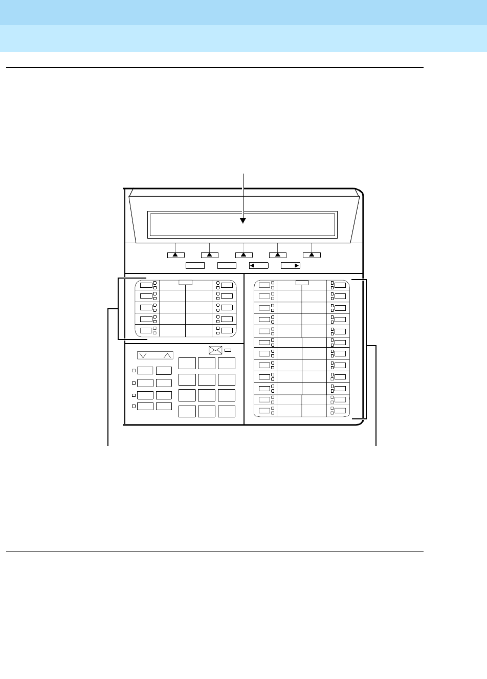
DEFINITYEnterpriseCommunicationsServerandSystem75andSystem85
Terminals and Adjuncts Reference
555-015-201 Issue 11
December 1999
The 8400 Series Voice Terminals
12-87The 8434 and 8434DX Voice Terminals
12
Figure 12-23. Button Numbering for Administering the 8434 and 8434DX Voice Terminal
Connected to a System 75, a DEFINITY G1 or G3, or a DEFINITY ECS
Volume
Ring Transfer
Test Conf
Mute Drop
Speaker Hold
123
456
789
ABC DEF
MNOJKLGHI
PQRS TUV WXYZ
*
O#
8434DX
NextPrev
Menu Exit
The 10 call appearance/feature
buttons in the left 2 columns are
administered as “BUTTON
ASSIGNMENTS” 1 through 10.
The 24 call appearance/feature
buttons in the right 2 columns are
administered as “FEATURE BUTTON
ASSIGNMENTS” 1 through 24.
(On the 7434 or 7444, these buttons
are labeled “BUTTON ASSIGNMENTS”
and numbered 11 through 34.)
If administered as a 7405D, administer the 15 softkey features as
“FEATURE MODULE BUTTON ASSIGNMENTS” 2 through 16.
AdministertheNormalfeatureonButton#1onthe“DISPLAY
BUTTON ASSIGNMENTS” screen.
If administered as itself, administer the 15 softkey features on
“SOFTKEY BUTTON ASSIGNMENTS” 1 through 15.
1
2
3
4
5
6
7
8
9
10
6
7
8
9
10
1
2
3
4
5
11
12
18
19
20
21
22
13
14
15
16
17
23
24
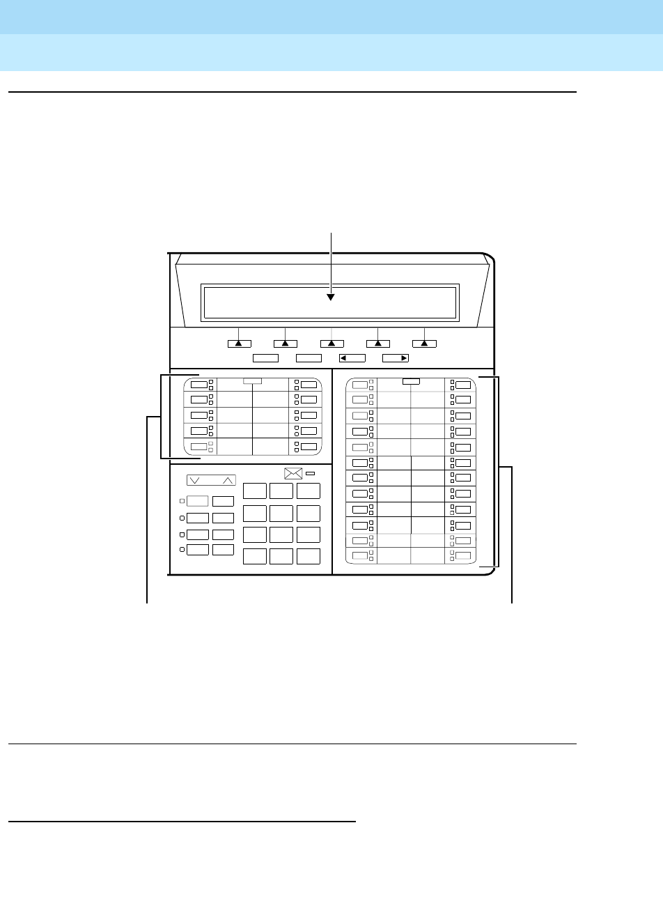
DEFINITYEnterpriseCommunicationsServerandSystem75andSystem85
Terminals and Adjuncts Reference
555-015-201 Issue 11
December 1999
The 8400 Series Voice Terminals
12-88The 8434 and 8434DX Voice Terminals
12
Figure 12-24. Button Numbering for Administering the 8434 and 8434DX Voice Terminal
Connected to a System 85 or a DEFINITY G2
Power Failure Operation
The 8434 and 8434DX voice terminals cannot be used as an emergency station
during power failure transfer conditions.
Volume
Ring Transfer
Test Conf
Mute Drop
Speaker Hold
123
456
789
ABC DEF
MNOJKLGHI
PQRS TUV WXYZ
*
O#
8434DX
NextPrevMenu Exit
The 10 call appearance/feature
buttons in the left 2 columns are
administered as “BUTTON
ASSIGNMENTS” 3 through 12.
The 24 call appearance/feature
buttons in the right 2 columns are
administered as “FEATURE BUTTON
ASSIGNMENTS” 13 through 36.
(On the 7434 or 7444, these buttons
are labeled “BUTTON ASSIGNMENTS”
and numbered 11 through 34.)
If administered as a 7405D, administer the 15 softkey features as
“FEATURE MODULE BUTTON ASSIGNMENTS” 2 through 16.
AdministertheNormalfeatureonButton#1onthe“DISPLAY
BUTTON ASSIGNMENTS” screen.
If administered as itself, administer the 15 softkey features on
“SOFTKEY BUTTON ASSIGNMENTS” 1 through 15.
3
4
5
6
7
8
9
10
11
12
18
19
20
21
22
13
14
15
16
17
23
24
30
31
32
33
34
25
26
27
28
29
35
36

DEFINITYEnterpriseCommunicationsServerandSystem75andSystem85
Terminals and Adjuncts Reference
555-015-201 Issue 11
December 1999
The 8400 Series Voice Terminals
12-89The 8434 and 8434DX Voice Terminals
12
FCC Registration
These voice terminals are FCC-registered along with the switch (as a system), but
do not have a separate FCC registration label.
UL and CSA Approval
These voice terminals have been tested and have met the Underwriters
Laboratories (UL) Standards UL 1459 and have also met the Canadian Standards
Association (CSA) Standards CSA-C22.2 No.225-M90.
Hearing Aid Compatible
These voice terminals are compatible with the inductively coupled hearing aids
prescribed by the FCC.
8434 and 8434DX Equipment PECs and Comcodes
The 8434 and 8434DX voice terminals and optional components can be ordered
with the following PECs and Comcodes:
■Basic 8434 (8434D04A) Voice Terminal
Black 8434 Set PEC: 3236-06B
Comcode: 106790439;
White 8434 Set PEC: 3236-06W
Comcode: 106790447
■Enhanced 8434DX (8434D04A) Voice Terminal
Black 8434DX Set PEC: 3236-06B
Comcode: 107707986;
White 8434DX Set PEC: 3236-06W
Comcode: 107707994
■K2S8 Handset
Comcode: Black=107545584; White=107545568
■Handset cord (9 feet)
Comcode: Black=407632819; White=407632835
■Line Cord (7 feet)
Comcode: 103786778
■Line cord (14 feet, silver)
PEC: 2725-07N COL18
Comcode: 103786802
■Line cord (25 feet, silver)
PEC: 2725-07S COL18
Comcode: 103786828

DEFINITYEnterpriseCommunicationsServerandSystem75andSystem85
Terminals and Adjuncts Reference
555-015-201 Issue 11
December 1999
The 8400 Series Voice Terminals
12-90The 8434 and 8434DX Voice Terminals
12
■Small Designation Card Cover (for 10 buttons on left of terminal)
PEC: 32309
Comcode: 846320216
■Large Designation Card Cover (for 24 buttons on right of terminal)
PEC: 32314
Comcode: 847037553
■Small Button designation card (for 10 buttons on left of terminal)
Tractor Feed For 25 Sets, 3 Sheets (12 cards per sheet)
PEC: 32310
Comcode: 847161817;
Tractor Feed For 100 Sets, 9 Sheets (12 cards per sheet)
PEC: 32311
Comcode: 847161916
■Large Button designation card (for 24 buttons on right of terminal)
Tractor Feed For 25 Sets, 13 Sheets (2 cards per sheet)
PEC: 32315
Comcode: 847141504;
Tractor Feed For 100 Sets, 50 Sheets (2 cards per sheet)
PEC: 32316
Comcode: 847168747
Adjuncts
The following adjuncts can be used with the 8434 and 8434DX voice terminals:
NOTE:
Auxiliary power is required when any adjuncts are added to the voice
terminal, except for the 7400B Plus Data Module which is AC powered. For
auxiliary power, an 1151A1 local power supply or an 1151A2 power supply
with Battery Holdover is recommended.
■An 801A Expansion Module can be connected to an 8434DX voice
terminal connected to a DEFINITY G3V3.3 (or later).
■S101A Speakerphone (no longer orderable)
■S201A Speakerphone
■CS201A Speakerphone
■7400B Plus Data Module in a 4-wire environment;
8400B Plus Data Module in a 2-wire environment
■500A Headset Adapter (and a standard headset; see “Headsets” on the
next page)
■K6S2 Amplifier Handset
■Shoulder Rest

DEFINITYEnterpriseCommunicationsServerandSystem75andSystem85
Terminals and Adjuncts Reference
555-015-201 Issue 11
December 1999
The 8400 Series Voice Terminals
12-91The 8434 and 8434DX Voice Terminals
12
Headsets
A list of compatible headsets, consisting of both modular and plug prong base
units and selection of headpieces, appears in “Headset Adapters” in the Adjuncts
section later in this manual.
Additional Documents
The following documents contain additional information relating to the 8434DX
voice terminal: (Use the 9-digit number listed after each document to order that
book from the BCS Publications Center for Lucent Technologies.)
■
8400-Series Voice Terminals Instructions for Installation, Switch
Administration, and Programming the Options
, 555-015-165
■
DEFINITY Communications System Generic 1 and 3 and System 75 8434
Voice Terminal User’s Guide
, 555-230-765
■
DEFINITY Communications System Generic 1 and 3 and System 75 8434
Voice Terminal Quick Reference Guide
, 555-230-766
■
DEFINITY Communications System Generic 2 and System 85 8434 Voice
Ter m in a l U se r’s Gu i de
, 555-104-765
■
DEFINITY Communications System Generic 2 and System 85 8434 Voice
Terminal Quick Reference Guide
, 555-104-766
■
DEFINITY Communications System Generic 1 and 3 and System 75
8434DX Voice Terminal User’s Guide
, 555-230-856
■
DEFINITY Communications System Generic 1 and 3 and System 75
8434DX Voice Terminal Quick Reference Guide
, 555-230-857
■
DEFINITY Communications System Generic 2 and System 85 8434DX
Voice Terminal User’s Guide
, 555-104-767
■
DEFINITY Communications System Generic 2 and System 85 8434DX
Voice Terminal Quick Reference Guide
, 555-104-768
■
801A Expansion Module Instruction Manual
, 555-015-136

DEFINITYEnterpriseCommunicationsServerandSystem75andSystem85
Terminals and Adjuncts Reference
555-015-201 Issue 11
December 1999
The 8400 Series Voice Terminals
12-92The 8434 and 8434DX Voice Terminals
12

CALLMASTER Voice Terminals
13-1
13
DEFINITYEnterpriseCommunicationsServerandSystem75andSystem85
Terminals and Adjuncts Reference
555-015-201 Issue 11
December 1999
13
CALLMASTER Voice Terminals
This section describes the following CALLMASTER voice terminals:
■CALLMASTER voice terminal
■CALLMASTER II voice terminal
■CALLMASTER III voice terminal
■CALLMASTER IV voice terminal
■CALLMASTER V voice terminal
■CALLMASTER VI voice terminal
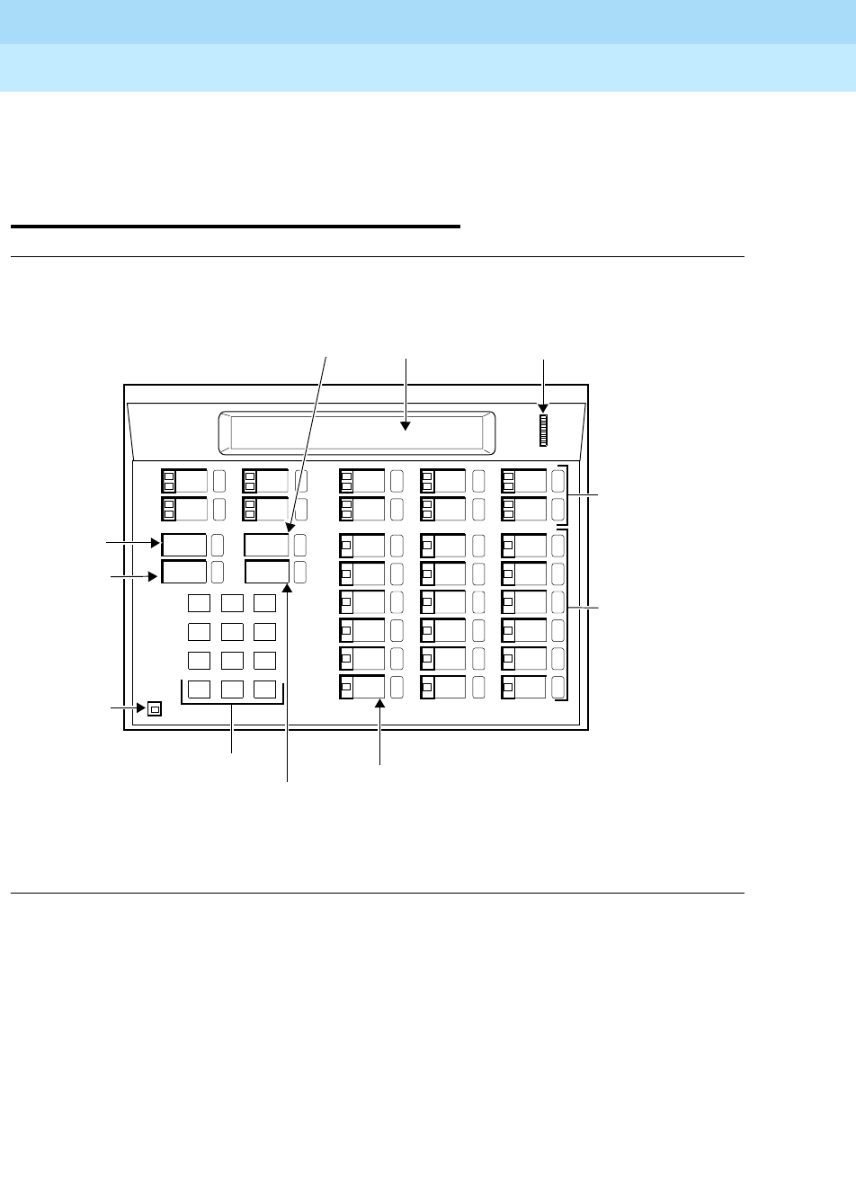
DEFINITYEnterpriseCommunicationsServerandSystem75andSystem85
Terminals and Adjuncts Reference
555-015-201 Issue 11
December 1999
CALLMASTER Voice Terminals
13-2
13
The CALLMASTER, CALLMASTER II,
CALLMASTER III, CALLMASTER IV,
CALLMASTER V, and
CALLMASTER VI Voice Terminals
Figure 13-1. The 602 CALLMASTER Voice Terminal
Drop
123
456
789
ABC DEF
MNOJKLGHI
PRS TUV WXY
*
O#
Oper
Conference Transfer
Hold
Mute
Message
Mute
Message
Alphanumeric
Transfer
Hold
Conference
Drop
CALLMASTER
Dial Pad Button
17 Administrable
Single Light
Light
Button
Button
Button
Button
10 Administrable
Single Light
Feature Buttons.
Display Area Display Control
Thumbwheel
Feature Buttons.
Button #6 Set to
Local Mute.
(Numbers 1-18 are
for identification
only)
(Numbers 1-18 are
for identification
only)
1
6
2
7
3
8
4
9
5
10
1
2
3
4
5
6
7
8
9
10
11
12
13
14
15
16
17
18
Release
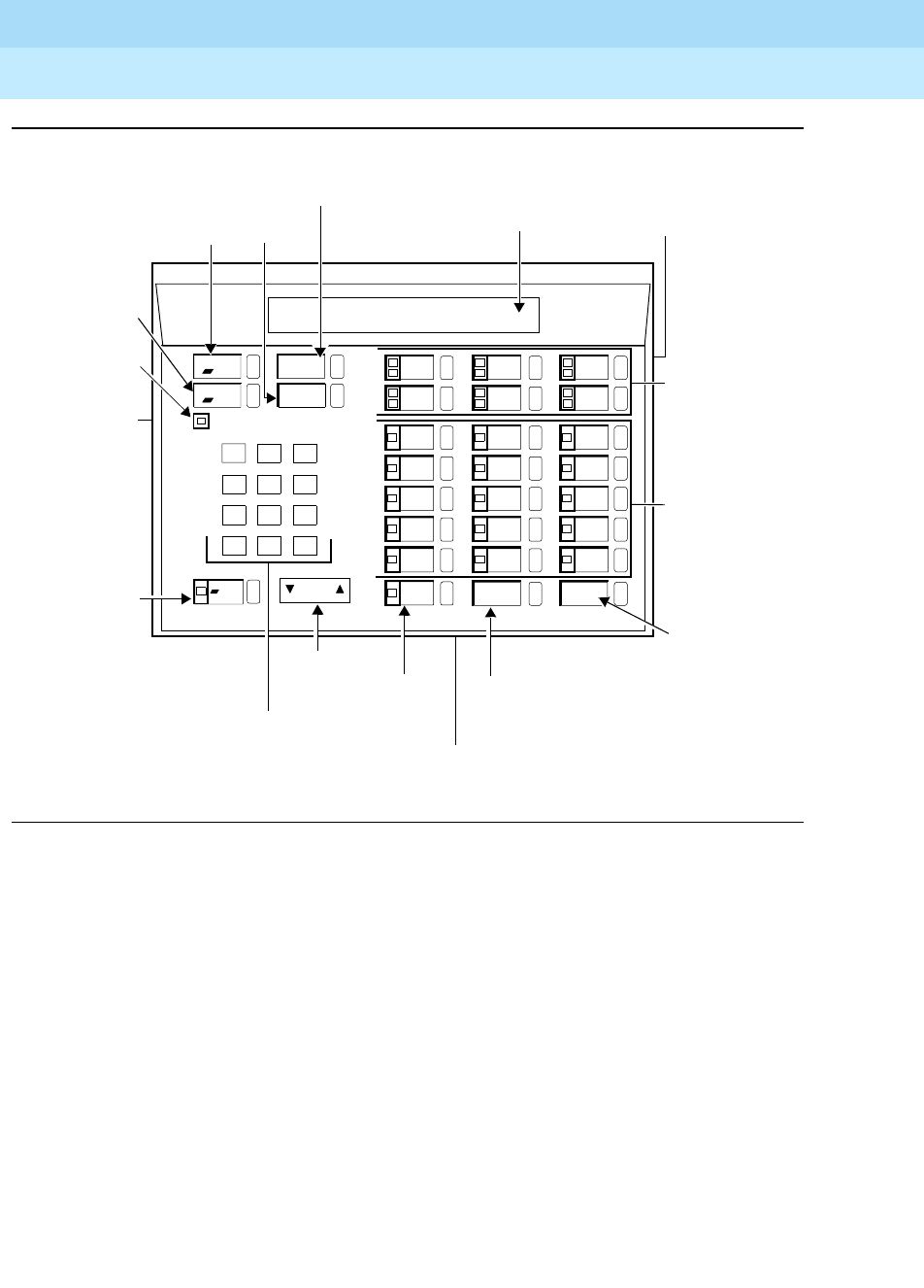
DEFINITYEnterpriseCommunicationsServerandSystem75andSystem85
Terminals and Adjuncts Reference
555-015-201 Issue 11
December 1999
CALLMASTER Voice Terminals
13-3
13
Figure 13-2. The CALLMASTER II and CALLMASTER III Voice Terminal
Drop
Test
Volume
123
456
789
ABC DEF
MNOJKLGHI
PQRS TUV WXYZ
*
O#
Oper
Conference Transfer
Hold
Select Mute
Message
Mute
Select
Message
Display
Transfer
HoldConference/Ring
Drop/Test
Volume
Ring
Log In Release
CALLMASTER III
Dial Pad
Control
Button Button
Adjunct Jack
(on back of terminal)
LogInButton
Release
Button
15 Feature
Buttons
Light
Button
Button
Headset
Adapter
Jack (on left
side of
Button
Button
Button
6 Call
Appearance/
Feature
Buttons
Headset
Adapter
Jack (on
right side
of terminal)
terminal)
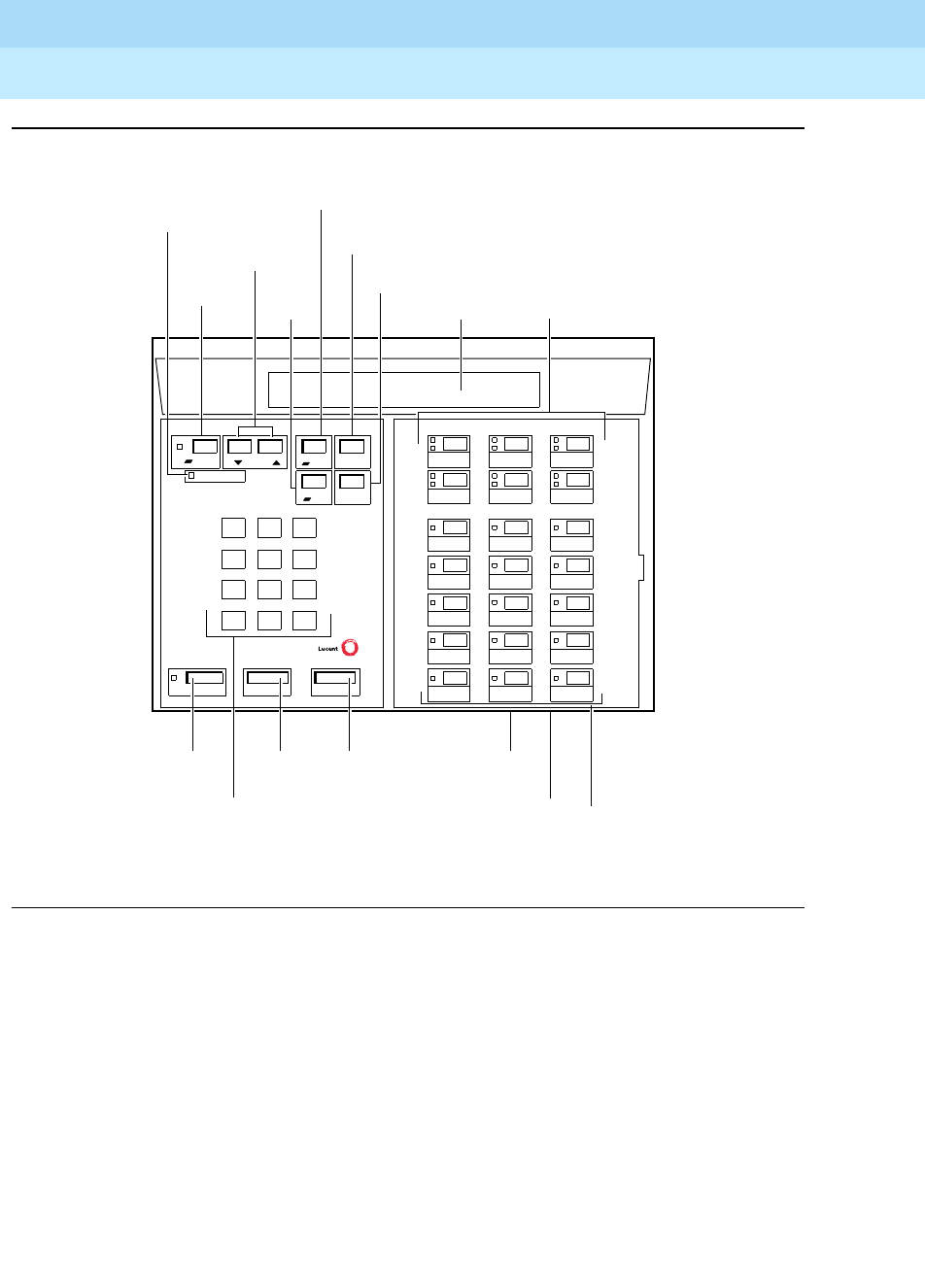
DEFINITYEnterpriseCommunicationsServerandSystem75andSystem85
Terminals and Adjuncts Reference
555-015-201 Issue 11
December 1999
CALLMASTER Voice Terminals
13-4
13
Figure 13-3. The CALLMASTER IV Voice Terminal
123
456
789
ABC DEF
MNOJKLGHI
PQRS TUV WXYZ
*
O#
Message
Mute
Message
6 Call Appearance/
Display
Transfer
Hold
Conference/
Drop/
Ring
CALLMASTER IV
Feature Buttons
Dial
Release
Button Adjunct Jack
(on bottom of
voice terminal)
15 Feature
Buttons
Line Jacks
(on bottom of
voice terminal)
Transfer
Conference
Test
Drop
Select Volume
ReleaseLog InMute
Button
Pad
Log In
Button
Button
Button
Ring Button
Test
Button
Light
Select
Button
Volume
Control
Buttons
Hold
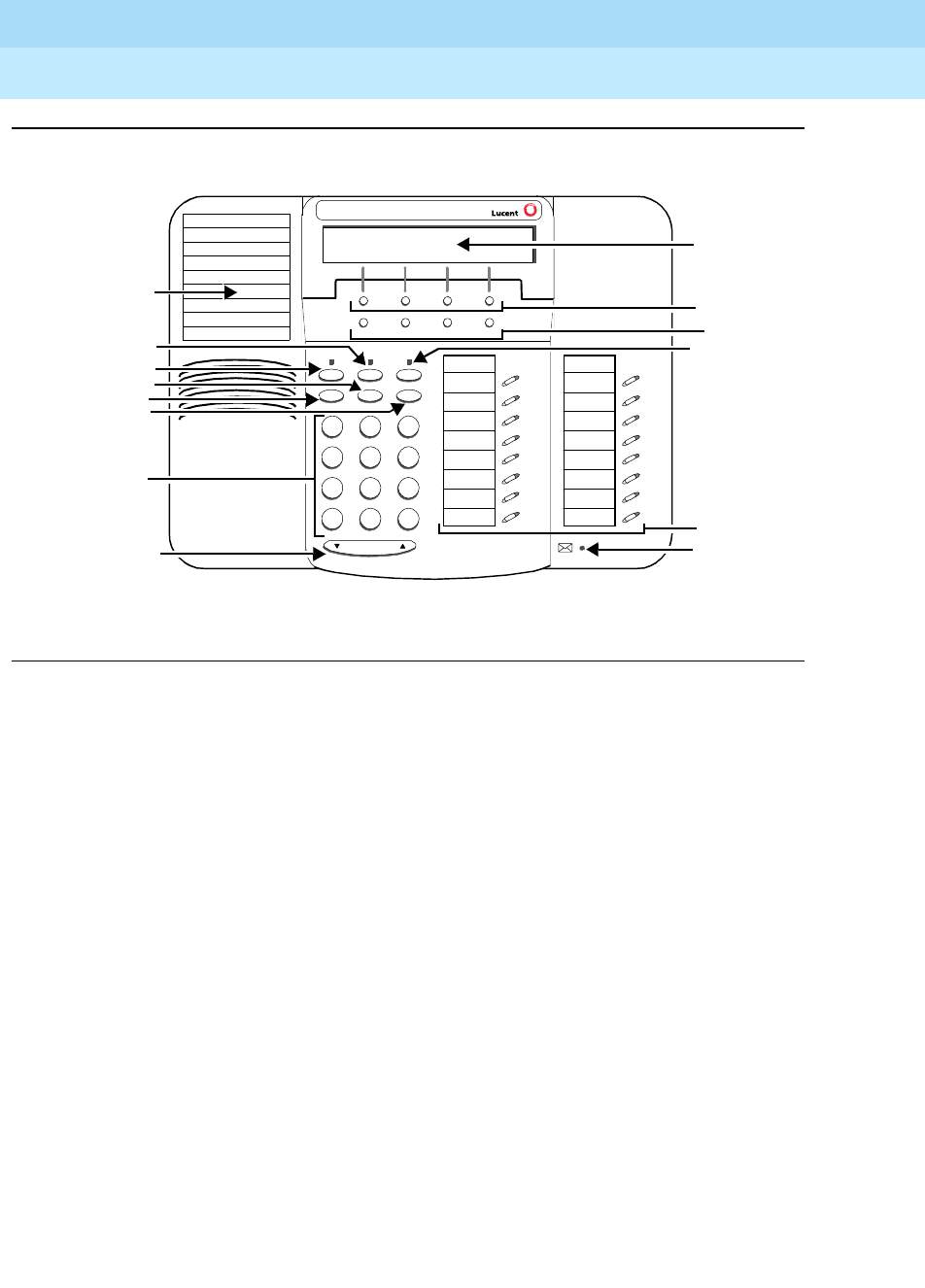
DEFINITYEnterpriseCommunicationsServerandSystem75andSystem85
Terminals and Adjuncts Reference
555-015-201 Issue 11
December 1999
CALLMASTER Voice Terminals
13-5
13
Figure 13-4. The CALLMASTER V Voice Terminal
7
PQRS
3
DEF
Speaker
Mute Hold
Redial
Transfer
Tes t Ring
2
ABC
1
4
GHI
*
56
89
MNOJKL
TUV WXYZ
O#
Vol ume
Tel #
CALLMASTER V
Menu Exit Prev Next
Conf
Display
Softkeys
Display control
buttons
8 Call Appearance/
Feature buttons
Message light
Hold button
Telephone
Notepad
Mute button
Speaker button
r
Transfer/Test button
Redial button
Conf/Ring button
Dial pad
Volume control button
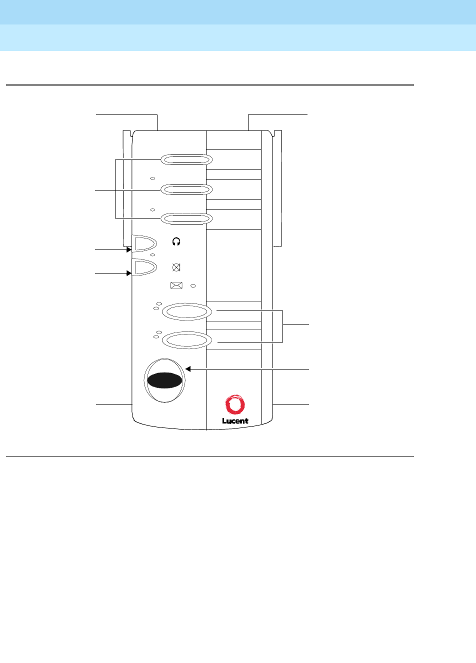
DEFINITYEnterpriseCommunicationsServerandSystem75andSystem85
Terminals and Adjuncts Reference
555-015-201 Issue 11
December 1999
CALLMASTER Voice Terminals
13-6
13
Figure 13-5. The CALLMASTER VI Voice Terminal
The CALLMASTER is a multi-appearance digital voice terminals used primarily as
a Call Management or Automatic Call Distribution (ACD) position. All
CALLMASTER models except the CALLMASTER VI, which will be described
further on in this chapter, are equipped with a 2-line by 40-character display that
can be used to provide information on incoming and outgoing calls. The unit can
be programmed to enter an After-Call Work State following each call for the
completion of service paperwork and can be configured for zip tone operation
where calls follow one another in a rapid sequence.
LINE Jack
(on rear of set)
CALLMASTER VI
EIA/TIA Data Jack
(on rear of set)
2 Call Appearance
Buttons
Release Button
Headset Jack
Headset Jack
3Feature
Buttons
Headset
On/Off Button
Mute Button
Headset On / Off
Mute
Message
a=
b=
Release
DEFINITYEnterpriseCommunicationsServerandSystem75andSystem85
Terminals and Adjuncts Reference
555-015-201 Issue 11
December 1999
CALLMASTER Voice Terminals
13-7
13
There are several types of CALLMASTER voice terminals:
■The 602 CALLMASTER comes in two models: the 602A and the 602D.
Although both of these models are the same in appearance, the 602D
CALLMASTER has a Recorder Interface which allows you to connect the
voice terminal to a recording device so that you can record all voice
interactions. The 602A does
not
have a recording interface.
■The 603D CALLMASTER, called the CALLMASTER II, comes with
Recorder Interface to record voice interactions.
■The 603E CALLMASTER, called the CALLMASTER III, comes without
Recorder Interface.
NOTE:
The CALLMASTER II and the CALLMASTER III are identical in appearance;
For easy identification, the model number is printed on a sticker on the
bottom of the voice terminal.
■The 603F1 CALLMASTER, called the CALLMASTER IV, comes in only one
model; it is equipped with a Recorder Interface.
■The 607A1 CALLMASTER, called the CALLMASTER V, comes in two
models, an English standard-labeled button set (that is, with buttons
labeled with Hold, Transfer, and so forth) and an icon-labeled set (that is,
with buttons labeled with icons such as , rather than Hold, and
instead of Transfer. Both the English-labeled and the icon sets
have a Recorder Interface.
■The 606A1 CALLMASTER, called the CALLMASTER VI, is much different
than the other CALLMASTERs since it works with an application software
package, usually Lucent CentreVu®Agent, through a connection with a
PC.
The 602 CALLMASTER has four fixed features (CONFERENCE, DROP, HOLD,
and TRANSFER), 10 call appearance/feature buttons, each with a red and green
light, 17 feature-only buttons, each with a green status light, a Message light, a
MUTE button, and a 2-line by 40-character display. The front panel of the
602 CALLMASTER drops down to reveal a SELF-TEST button, a Ringer-volume
control, and a 1-2 switch which can be set only by an installer.
The CALLMASTER II and III models have four fixed features (CONFERENCE,
DROP, HOLD, and TRANSFER), six call appearance/feature buttons, each with a
red and green light, 15 feature-only buttons, each with a green status light, a
Message light, a MUTE button, a SELECT button, a LOG IN and RELEASE
button used for processing ACD calls, and a 2-line by 40-character supertwist
liquid crystal display.
The CALLMASTER IV has a 2-line by 40-character liquid crystal display, four fixed
features (CONFERENCE/RING, DROP/TEST, HOLD, and TRANSFER), a
SELECT button, two Volume control buttons (one for raising the volume and one
for lowering the volume), and a Message light, all at the top of the voice terminal.

DEFINITYEnterpriseCommunicationsServerandSystem75andSystem85
Terminals and Adjuncts Reference
555-015-201 Issue 11
December 1999
CALLMASTER Voice Terminals
13-8
13
The CALLMASTER IV set also has six call appearance/feature buttons, each with
a red and green light, and 15 feature-only buttons, each with a green status light.
At the bottom of the CALLMASTER IV is a MUTE button, a LOG IN and
RELEASE button used for processing ACD calls.
The CALLMASTER V is very similar to the 6416D+ telephone, since it can only be
used in a 2-wire environment, has 16 call appearance/feature buttons, and has a
display with softkeys and display control buttons with which the user can access
other features besides those administered on feature buttons. These telephones
also have six standard fixed feature buttons: a SPEAKER button, which can
access a one-way, listen-only speakerphone, MUTE button to mute the handset, a
red HOLD button, REDIAL button, TRANSFER/TEST button for transferring a call
or testing the lights and display on the telephone, and a CONF/RING button for
setting up a conference call and for selecting a personalized ringing pattern.
These telephones also have a red Message light and a Volume control button.
The CALLMASTER VI is a miniature voice terminal which has two call
appearance buttons with a red and green light beside each button, three feature
buttons, two of which have an associated green light, a MUTE button and a
HEADSET ON/OFF button which share a red light, and a blue RELEASE button.
Other features can also be used according to the software application on the PC.
On each of the two sides of the 602 CALLMASTER, the CALLMASTER II,
CALLMASTER III, CALLMASTER IV, and CALLMASTER VI, there is a headset
jack in which you can plug in a headset or, if special adapters are used, a handset.
(The CALLMASTER V also has a headset jack; however, it is located on the
bottom of the set.)
On the rear of the 602 CALLMASTER, there is a jack for an optional kneewall
adapter. You can plug two headsets or two handsets into this adapter. (Both
headsets or handsets must be the same model.)
Applications
The 602 CALLMASTER can be used with the DEFINITY Communications System
Generic 1, Generic 2, and Generic 3, the DEFINITY ECS, System 75 (R1V3 or
later), and System 85 (R2V2 or later).
The 603 voice terminals, which include the CALLMASTER II, CALLMASTER III,
and CALLMASTER IV, can be used only with a DEFINITY ECS G3V3 and later.
The CALLMASTER V and CALLMASTER VI work only with a DEFINITY ECS
Release 6.1. These voice terminals are especially suitable for Call Management
or ACD call-handling positions.

DEFINITYEnterpriseCommunicationsServerandSystem75andSystem85
Terminals and Adjuncts Reference
555-015-201 Issue 11
December 1999
CALLMASTER Voice Terminals
13-9
13
Special Operational Characteristics
The CALLMASTER voice terminals do not have a physical switchhook or handset
cradle (although a handset cradle kit can be ordered separately). These sets are
on-hook when there is no headset plugged physically into either of the two
headset jacks. The voice terminals are off-hook when one or more headsets are
plugged into one of the headset jacks.
The Recorder Interface
The 602D CALLMASTER, the CALLMASTER II, the CALLMASTER IV, and the
CALLMASTER V voice terminals provide a recorder interface which is designed
for recording calls on a standard analog tape recorder. (A recorder with AGC
[Automatic Gain Control] is recommended on the CALLMASTER II with Recorder
Interface.) With this interface, a warning tone (a soft beep repeated every 15
seconds) notifies the agent and the calling party that the call is being recorded.
Be
aware that this tone may be a legal requirement.
NOTE:
The default setting for the Recorder Interface and the Recording Warning
Tones on the CALLMASTER II with Recorder Interface is “Enabled”; on the
CALLMASTER IV and CALLMASTER V, the default for both of these
features is “Disabled.” However, the interface and the warning tones can
always be changed to the enabled or disabled state. For directions on
enabling and disabling these two features on the CALLMASTER II, III, and
IV, see the
DEFINITY ECS CALLMASTER II, CALLMASTER III, and
CALLMASTER IV Voice Terminals Instructions for Programming the
Options,
555-015-172.
The application software installed on the PC to which the CALLMASTER VI is
connected has an Announcements Recorder feature which enables recording and
playback of personalized announcements. The user can record up to six
announcements at a length of 9.6 seconds per announcement. The application
software provides the user interface to record and play back the announcements,
while the CALLMASTER VI provides the sound chip for which announcements
are recorded and stored.
Physical Description
Dimensions
The following dimensions for the 602 CALLMASTER, CALLMASTER II,
CALLMASTER III, and CALLMASTER IV are approximate.
Width = 11 inches
Depth (front to back) = 8-1/2 inches
Height = 5-1/2 inches

DEFINITYEnterpriseCommunicationsServerandSystem75andSystem85
Terminals and Adjuncts Reference
555-015-201 Issue 11
December 1999
CALLMASTER Voice Terminals
13-10
13
The following are the approximate dimensions for the CALLMASTER V:
Width = 10.35 inches (26.35 cm)
Depth (front to back) = 8.5 inches (21.59 cm)
Height (with deskstand and handset in place) = 4.75 inches (12.07 cm)
The dimensions directly below for the CALLMASTER VI are also approximate.
Width = 3-1/4 inches
Depth (front to back) = 7-1/4 inches
Height = 2 inches (at the top of the terminal);
1-1/8 inches (at the bottom of the terminal)
Features
Four Fixed Feature Buttons
The 602 CALLMASTER, CALLMASTER II, CALLMASTER III,
CALLMASTER IV, and CALLMASTER V have the following fixed feature buttons:
■CONFERENCE or CONFERENCE/RING button
■DROP or DROP/TEST button
■TRANSFER button
■HOLD button
Message Light
The Message light goes on when a message is left for the user. It goes off when
the user retrieves the message. On the 602 CALLMASTER, the Message light is
green; on the CALLMASTER II, CALLMASTER III, CALLMASTER IV,
CALLMASTER V, and the CALLMASTER VI, the Message light is red.
Call Appearance/Feature Buttons
The 602 CALLMASTER voice terminal has 10 call appearance/feature buttons;
the CALLMASTER II, CALLMASTER III, and CALLMASTER IV have six call
appearance/feature buttons; the CALLMASTER V has 16 call appearance/feature
buttons. The CALLMASTER VI has two call appearance buttons. Each of these
buttons has a red appearance light and a green status light stacked to the left of
the button. On all of these CALLMASTER models except the CALLMASTER VI,
these buttons can be used as call appearances or for features that are assigned
during administration. On the CALLMASTER VI, the two call appearance buttons
are used only as call appearances.
Feature-Only Buttons
The 602 CALLMASTER voice terminal has 17 feature buttons; the
CALLMASTER II, CALLMASTER III, and CALLMASTER IV have 15 feature
buttons. The CALLMASTER VI has three feature buttons. Each button, except for

DEFINITYEnterpriseCommunicationsServerandSystem75andSystem85
Terminals and Adjuncts Reference
555-015-201 Issue 11
December 1999
CALLMASTER Voice Terminals
13-11
13
the top feature button on the CALLMASTER VI, has a green status light
associated with it. These buttons can be used for features assigned during
administration.
NOTE:
The CALLMASTER V does not have any Feature-Only buttons.
Listen-Only SPEAKER
Only the CALLMASTER V has a one-way, listen-only speaker. If the user wishes
to speak to the caller, he/she must use the headset (or, if applicable, the handset).
MUTE Button
All CALLMASTER sets have a MUTE button, a fixed feature button. The Mute
feature allows the user to be in a listen-only mode. On the 602 CALLMASTER, the
MUTE button light is green; on the CALLMASTER II, CALLMASTER III,
CALLMASTER IV, CALLMASTER V, and the CALLMASTER VI, the light next to
the MUTE button is red.
NOTE:
The default setting for the Mute feature on all the CALLMASTER sets
is “Enabled.” For directions on enabling and disabling the Mute
feature on the CALLMASTER II, III, and IV, see the
DEFINITY ECS
CALLMASTER II, CALLMASTER III, and CALLMASTER IV Voice
Terminals Instructions for Programming the Options
, 555-015-172.
SELECT button
The CALLMASTER II and III and the CALLMASTER IV voice terminals have a
SELECT button that can be used in two different ways: (The green light next to the
SELECT button goes on steadily when the SELECT button is activated.)
■Used with the CONFERENCE/RING button to select one of eight
personalized ringing patterns for incoming calls
■Used with the DROP/TEST button to initiate the Self-Test feature which
tests the lights, ringer, and display
VOLUME control button
The 602 CALLMASTER has a volume control slide switch behind the front panel.
This slide switch controls the volume of the tone ringer.
The CALLMASTER II, III, and V terminals have a VOLUME “arrow” button with a
double function. When the user is on a call, the VOLUME button controls the
volume of incoming transmission on the headset or handset whichever is being
used; when the user is not on a call, the VOLUME control button adjusts the tone
ringer. On the CALLMASTER IV voice terminal there are two separate volume
control buttons, one to lower the volume and one to raise the volume.

DEFINITYEnterpriseCommunicationsServerandSystem75andSystem85
Terminals and Adjuncts Reference
555-015-201 Issue 11
December 1999
CALLMASTER Voice Terminals
13-12
13
When the user sets the volume for the headset or handset or for the tone ringer on
the CALLMASTER II and III, IV, or on the CALLMASTER V, the display on the
voice terminal shows a “bar array” that indicates the volume setting.
LOG IN and RELEASE buttons
On the CALLMASTER II, CALLMASTER III, and CALLMASTER IV, the LOG IN
and RELEASE buttons are located in the bottom row of feature buttons. These
buttons
must
be used for these two ACD features: the Log in feature and the
Release feature.
No other feature should be administered on these buttons.
The CALLMASTER VI has three feature buttons at the top of the set on which
there may be programmed such ACD features as Log In/Off, Auto In, or Assist.
This voice terminal also has a dedicated blue RELEASE button.
NOTE:
The CALLMASTER V does not have a dedicated RELEASE or HANDSET
ON/OFF button. These features must be administered on blank buttons on
the set.
Self-Test
On the 602 CALLMASTER, the user presses and holds down a SELF-TEST
button behind the front panel of the set to perform a self-test of the lights, display,
and the ringer.
On the CALLMASTER II, CALLMASTER III, and CALLMASTER IV, the user
presses the SELECT button and then presses and holds down the DROP/TEST
button to initiate a test of the lights, ringer, and display on the voice terminal. The
CALLMASTER V has a TRANSFER/TEST button.
Display
All CALLMASTER voice terminals, except the CALLMASTER VI, have a 2-line by
40-character per-line display located at the top of the voice terminal. (The
CALLMASTER VI is connected to a PC, and the agent using this voice terminal
views the telephone and ACD feature information on the PC screen.) By using the
voice terminal display, the user can retrieve personal messages or display queue
status without losing call identification. The terminal displays call appearance-
related information on the first line. All non-call appearance-related and local
information is displayed on the second line of the display.
The 602 CALLMASTER has a display contrast thumbwheel which can be rotated
to make the display contrast darker or lighter.
NOTE:
The CALLMASTER II, CALLMASTER III, and CALLMASTER IV can be
optioned for a 1-line or a 2-line display. The 2-line (by 40 characters) format
is the expected normal usage. The 1 line format is needed only when the

DEFINITYEnterpriseCommunicationsServerandSystem75andSystem85
Terminals and Adjuncts Reference
555-015-201 Issue 11
December 1999
CALLMASTER Voice Terminals
13-13
13
CALLMASTER is administered as a 7405D with a D401 display, as a 7406D,
or as any other set with a 1-line display format. The default is the
2-line display. To change this setting, see the
DEFINITY ECS
CALLMASTER II, CALLMASTER III, and CALLMASTER IV Voice Terminals
Instructions for Programming the Options,
555-015-172.
Other Physical Features
Headsets
The CALLMASTER voice terminals are designed to use carbon miked headsets.
A maximum of two headsets can be connected at the same time. The quality of
transmission may be affected if different types of headsets are used together.
Handset
An optional K-type handset kit is available for the CALLMASTER voice terminals.
This kit contains a handset cradle, a handset, and the required adapter. The
handset plugs into the headset jack and functions as though a headset was being
used. This handset does not provide switchhook capabilities.
Dial pad
All CALLMASTER models, except the CALLMASTER VI, are equipped with a
12-button touch-tone dial pad. On the CALLMASTER VI, the user can use the dial
pad on the screen of the PC connected to the voice terminal.
Jacks
The 602 CALLMASTER, CALLMASTER II, CALLMASTER III, CALLMASTER IV,
and CALLMASTER VI voice terminals’ housing contains three jacks. The line cord
jack is located on the rear of the unit. Two PJ327 type (2-prong) jacks allow the
headset or optional handset to be plugged into either side of the unit. The
CALLMASTER V has a line cord jack, a headset jack, and a handset jack (which
can be used for a headset), all on the bottom of the set.
NOTE:
SincetheCALLMASTERIVcanbeusedina2-wireOR4-wiresetting,this
voice terminal has two Line jacks, one for 2-wire operation and one for
4-wire operation.
The CALLMASTER II, CALLMASTER III, and CALLMASTER IV also have
another jack, an Adjunct jack, located on the back of the voice terminal for
connecting adjunct equipment to the voice terminal.
The CALLMASTER VI also has another jack, not located on the other
CALLMASTER sets, an EIA Data jack located on the rear of the voice terminal. An
EIA/TIA-574 cable connected to this Data jack on the CALLMASTER VI and, at
the other end, to a Serial COM port on a PC provides full access to the application
software, such as CentreVu Agent, loaded on the PC.

DEFINITYEnterpriseCommunicationsServerandSystem75andSystem85
Terminals and Adjuncts Reference
555-015-201 Issue 11
December 1999
CALLMASTER Voice Terminals
13-14
13
Cords
A D8W-87 line cord and a Handset cord are provided with all CALLMASTER voice
terminals. An EIA/TIA Data cord is also shipped in the box with the CALLMASTER
VI set.
Kneewell Adapter (602 CALLMASTER only)
An optional adapter is available for connecting two headsets or handsets to the
602 CALLMASTER. This adapter allows the handset or headset to be connected
without the cords running across the top of the desk.
Ringing
The CALLMASTER voice terminals have electronic tone ringing with patterns that
are set at administration.
Mounting Options
All the CALLMASTER voice terminals, except the CALLMASTER VI, are only
available as a desk model; they cannot be wall mounted. The CALLMASTER VI
can be used on a flat surface such as a desk, or it can be mounted with velcro
strips on a wall or on the side of the PC.
Color Options
The 602 CALLMASTER is available in black and misty cream. The CALLMASTER
II, CALLMASTER III, and CALLMASTER IV sets are available in black, misty
cream, and white. The CALLMASTER V is available in gray and white. The
CALLMASTER VI is available only in international (charcoal) gray.

DEFINITYEnterpriseCommunicationsServerandSystem75andSystem85
Terminals and Adjuncts Reference
555-015-201 Issue 11
December 1999
CALLMASTER Voice Terminals
13-15
13
Wiring Information on the CALLMASTER IV
The CALLMASTER IV voice terminal works in both 4-wire and 2-wire DCP
configurations. The table on the next page shows pin assignments for the line cord
and jack block interface
*U-T=“Tip”
U-R = “Ring”
Table 13-1. The DCP Line Interface for the CALLMASTER IV
CONNECTOR BLOCK DCP JACK INTERFACE
Conn.
Block Pin
Number
DInside
Wire
Color
Pin Name Signal Description
3 W-O 1 OD1 Balance output from
telephone (power –48V)
4-wire application
REC-1 Output to Recorder
2-wire application
4 O-W 2 OD2 Balance output from
telephone (power –48V)
4-wire application
REC-2 Output to Recorder
2-wire application
5 W-G 3 ID1 Balance input from PBX
(power –48V)
4-wire application
2-wire — unused
1 W-BL 4 REC-1 Output to Recorder
4-wire application
U-T* Balanced output from
telephone (power –48V)
2-wire application
2 BL-W 5 REC-2 Output to Recorder
4-wire application
U-R* Balanced output from PBX
(power 0v)
2-wire application
6 G-W 6 ID2 Balanced input from PBX
(power 0v)
4-wire application
2-wire — unused
7 W-BR 7 P1– Adjunct power –48V
(to Adjunct jack)
8 BR-W 8 P2+ Adjunct power common
(to Adjunct jack)

DEFINITYEnterpriseCommunicationsServerandSystem75andSystem85
Terminals and Adjuncts Reference
555-015-201 Issue 11
December 1999
CALLMASTER Voice Terminals
13-16
13
The design of this product allows it to operate on either 2-wire or 4-wire DCP circuits. In
order for the terminal to function properly in either 2-wire or 4-wire installations, there
must be NO INTERCONNECTIONS between the wire pairs used for 2-wire and 4-wire
operation. Bridging or paralleling of these pairs can result in damage to the terminal or
can cause the PBX circuit pack to remove power to the terminal.
REMOVE ALL CONNECTIONS BETWEEN PAIRS BEFORE CONNECTING THE
TERMINAL.
For 2-wire operation, if you need to plug the voice terminal into a 4-pin or 6-pin wall jack,
instead of a standard 8-pin modular jack, refer to the “Modular Wall Jack Wiring” table on
the next page to insure that the wires from the 4-pin or 6-pin wall jack are connected to
the correct pins on the terminal 2-wire “LINE” jack.
4-WIRE installations MUST ONLY have PBX connections on pair 2 and pair 3 and, if
necessary, auxiliary power must be connected to pair 4.
2-WIRE installations MUST ONLY have PBX connections on pair 1 and, if necessary,
auxiliary power must be connected to pair 4.
Wiring Note for the CALLMASTER VI
All wiring between the DEFINITY ECS and the CALLMASTER VI, including the
line cord, must consist of twisted pairs. Twisted-pair wiring makes lines less
sensitive to crosstalk. The line cord must be a D8W, which consists of four twisted
pairs, or a Lucent Technologies-approved equivalent.
Distance Limitations
The maximum allowable distances the CALLMASTER voice terminals can be
located from the DEFINITY G1, G2, and G3, DEFINITY ECS, System 75, or
System 85 cabinet is shown in the table below.
NOTE:
The 602 CALLMASTER can be connected to any of the switches listed
directly above. However, the CALLMASTER II and CALLMASTER III are
only supported when connected to a DEFINITY G3. The CALLMASTER IV
is supported only when connected to a DEFINITY G3V3.

DEFINITYEnterpriseCommunicationsServerandSystem75andSystem85
Terminals and Adjuncts Reference
555-015-201 Issue 11
December 1999
CALLMASTER Voice Terminals
13-17
13
Notes:
These ranges can be extended to 5,000 feet (1524 m) for 24 AWG wire and 4,000 feet
(1219 m) for 26 AWG wire with the use of a Data Link Protector. Refer to EXPOSED PORT
PROTECTION.
In 2-wire installations, the CALLMASTER III and CALLMASTER IV can be connected to a
TN2181 port board.
Distance Limitations for the CALLMASTER V
and CALLMASTER VI
In a 2-wire installation, the CALLMASTER V and the CALLMASTER VI is
connected to a TN2181 port board located in a cabinet with DEFINITY G3
Release 6.1 or later software. Use the following distance limitations between the
CALLMASTER V and CALLMASTER VI and the DEFINITY ECS:
If you are using 22-gauge wire for the connection, the two pieces of equipment
must be within 5,500 feet of each other; if you are using 24-gauge wire, the two
must be within 3,500 feet; if you are using 26-gauge wife, the two must be within
2,200 feet.
Power Requirements
The CALLMASTER voice terminals receive power from the system and do not
require any external power supply. However, adjunct equipment connected to the
CALLMASTER II, CALLMASTER III, and CALLMASTER IV needs its own power
supply.
Switch Administration
The 602 CALLMASTER can be used with a DEFINITY G1, G2, and G3, a
DEFINITY ECS, and System 75 (R1V3) and System 85 (R2V2 through R2V4).
The 602 CALLMASTER can be administered as itself.
Table 13-2. Distance Limitations for the CALLMASTER II, III, and IV Voice
Te rm i n a ls
(See Note above for a list of supported connections for each set)
System Port Board
Nominal Maximum Range in
Feet (Meters) (See Note)
24 AWG 26 AWG
DEFINITY G2
System 85
SN270B
TN754
3,400 (1,034)
3,400 (1,034)
2,200 (671)
2,200 (671)
DEFINITY G1
and G3,
DEFINITY ECS,
and System 75
TN754 3,400 (1,034) 2,200 (671)

DEFINITYEnterpriseCommunicationsServerandSystem75andSystem85
Terminals and Adjuncts Reference
555-015-201 Issue 11
December 1999
CALLMASTER Voice Terminals
13-18
13
The CALLMASTER II, CALLMASTER III, and CALLMASTER IV can be used only
with a DEFINITY ECS G3V3 and above. The CALLMASTER II and
CALLMASTER III must be aliased as a 602 CALLMASTER. The
CALLMASTER IV voice terminal can be administered as itself.
The CALLMASTER V and CALLMASTER VI can be used only with a DEFINITY
ECS Release 6.1 and later releases. The CALLMASTER V must be aliased as a
6416D+ telephone.
If the CALLMASTER VI is connected to a DEFINITY ECS switch, Release 7.1 and
prior, the CALLMASTER VI must be aliased as a 603E CALLMASTER. If the
CALLMASTER VI is connected to a DEFINITY ECS, Release 7.1 and later, the
CALLMASTER VI can be administered as itself.
Button Numbering
The following button diagram of the 602 CALLMASTER voice terminal will help
you administer this voice terminal connected to a System 75 (R1V3 or later), a
DEFINITY G1 and G3, and DEFINITY ECS, and to a System 85 (R2V2 or later) or
aDEFINITYG2.
The CALLMASTER II and CALLMASTER III can be connected only to a
DEFINITY G3.
The CALLMASTER IV is supported only with a DEFINITY G3V3.
The CALLMASTER V and VI are supported only with a DEFINITY G3
Release 6.1.
Figures 13-6 and 13-7 show button numbering for the 602 CALLMASTER.
Figure 13-8 shows button numbering for the CALLMASTER II and III.
Figure 13-9 shows button numbering for the CALLMASTER IV.
Figure 13-10 shows button numbering for the CALLMASTER V.
Figure 13-11 shows button numbering for the CALLMASTER VI.
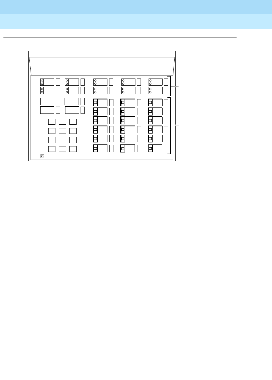
DEFINITYEnterpriseCommunicationsServerandSystem75andSystem85
Terminals and Adjuncts Reference
555-015-201 Issue 11
December 1999
CALLMASTER Voice Terminals
13-19
13
Figure 13-6. Button Numbering for Administering the 602 CALLMASTER
Voice Terminal Connected to a System 75, a DEFINITY G1 or G3,
or a DEFINITY ECS
Drop
123
456
789
ABC DEF
MNOJKLGHI
PRS TUV WXY
*
O#
Oper
Conference Transfer
Hold
Mute
Message
Release
5
* Feature Button #6 is preassigned as a Mute Button. It is recommended that
Feature Button
Assignments
Button
Assignments
1-10
1-18
10
4
9
3
8
2
7
1
6
Feature Button #18 be administered as a Release Button.
6
1
2
3
4
5
12
7
8
9
10
11
18
13
14
15
16
17
*
*

DEFINITYEnterpriseCommunicationsServerandSystem75andSystem85
Terminals and Adjuncts Reference
555-015-201 Issue 11
December 1999
CALLMASTER Voice Terminals
13-20
13
Figure 13-7. Button Numbering for Administering the 602 CALLMASTER
Voice Terminal Connected to a System 85 or a DEFINITY G2
Drop
123
456
789
ABC DEF
MNOJKLGHI
PRS TUV WXY
*
O#
Oper
Conference Transfer
Hold
Mute
Message
8
NOTE: The Hold Button is Button #1.
Feature Button
Assignments
Button
Assignments
3-12
13-30
12
7
11
6
10
5
9
3
8
18
13
14
15
16
17
24
19
20
21
22
23
30
25
26
27
28
29
The Message Light is Button #2.
The Mute Button is Button #18.
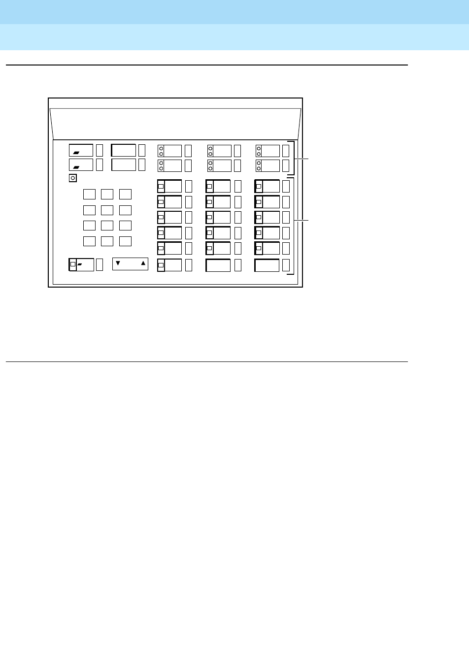
DEFINITYEnterpriseCommunicationsServerandSystem75andSystem85
Terminals and Adjuncts Reference
555-015-201 Issue 11
December 1999
CALLMASTER Voice Terminals
13-21
13
Figure 13-8. Button Numbering for Administering the CALLMASTER II or
CALLMASTER III Voice Terminal Connected to a DEFINITY ECS G3
Drop
Test
Volume
123
456
789
ABC DEF
MNOJKLGHI
PQRS TUV WXYZ
*
O#
Oper
Conference Transfer
Hold
Select Mute*
Message
Ring
Log In* Release*
*Feature Button #6 is preassigned as a Mute Button.
Feature Button
Assignments
Button
Assignments
1-6
Administer Feature Button #12 as a
LogInButtonandFeatureButton#18
as a Release Button.
1-18
6
1
2
3
4
5
7
8
9
10
11
12
3
6
2
5
1
4
13
14
15
16
17
18
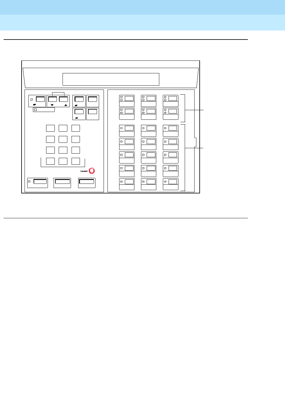
DEFINITYEnterpriseCommunicationsServerandSystem75andSystem85
Terminals and Adjuncts Reference
555-015-201 Issue 11
December 1999
CALLMASTER Voice Terminals
13-22
13
Figure 13-9. Button Numbering for Administering the CALLMASTER IV Voice
Terminal Connected to a DEFINITY ECS G3V3 or Later
123
456
789
ABC DEF
MNOJKLGHI
PQRS TUV WXYZ
*
O#
Message
Ring
CALLMASTER IV
Transfer
Conference
Test
Drop
Select Volume
ReleaseLog InMute
Hold
1
2
3
4
5
6
7
8
9
10
11
12 18
13
14
15
16
17
1
4
2
5
3
6
Feature Button
Assignments
1–18
Button
Assignments
1–6
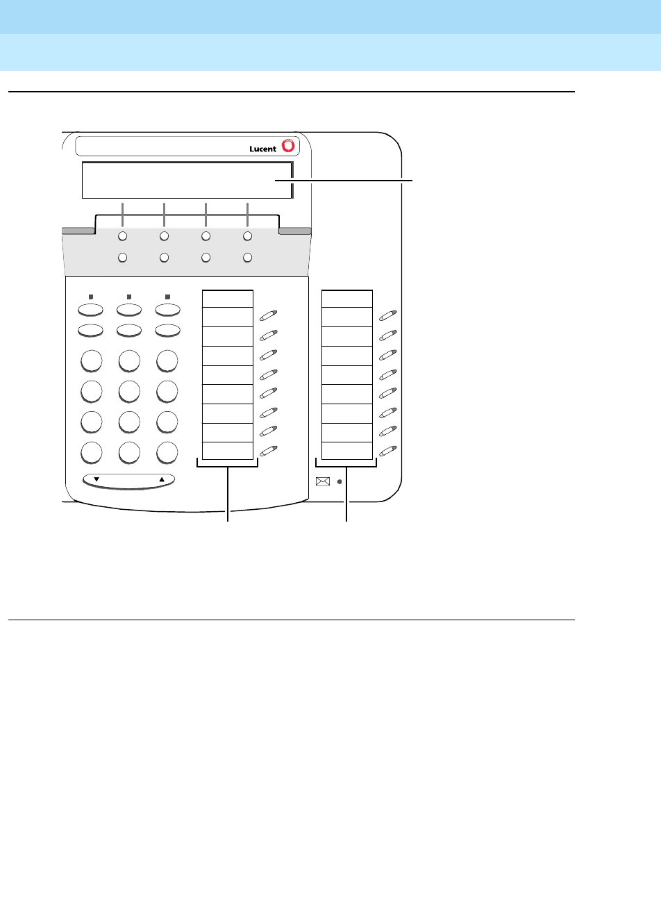
DEFINITYEnterpriseCommunicationsServerandSystem75andSystem85
Terminals and Adjuncts Reference
555-015-201 Issue 11
December 1999
CALLMASTER Voice Terminals
13-23
13
Figure 13-10. Button Numbering for Administering the CALLMASTER V Telephone
Console Connected to a DEFINITY ECS Release 6.1 and Later
7
PQRS
3
DEF
Speaker Mute Hold
Redial Transfer Conf
Test Ring
2
ABC
1
4
GHI
*
56
89
MNOJKL
TUV WXYZ
O#
Volume
Menu Exit Prev Next
Tel #
1
2
3
4
5
6
7
8
9
10
11
12
13
14
15
16
Administer the first
column of 8 call appearance/
features buttons as “BUTTON
ASSIGNMENTS” 1 - 8.
Administer the second column
as “FEATURE BUTTON
ASSIGNMENTS” 9 - 16.
Administer the 12 softkey
features on “SOFTKEY
BUTTON ASSIGNMENTS”
1 through 12.
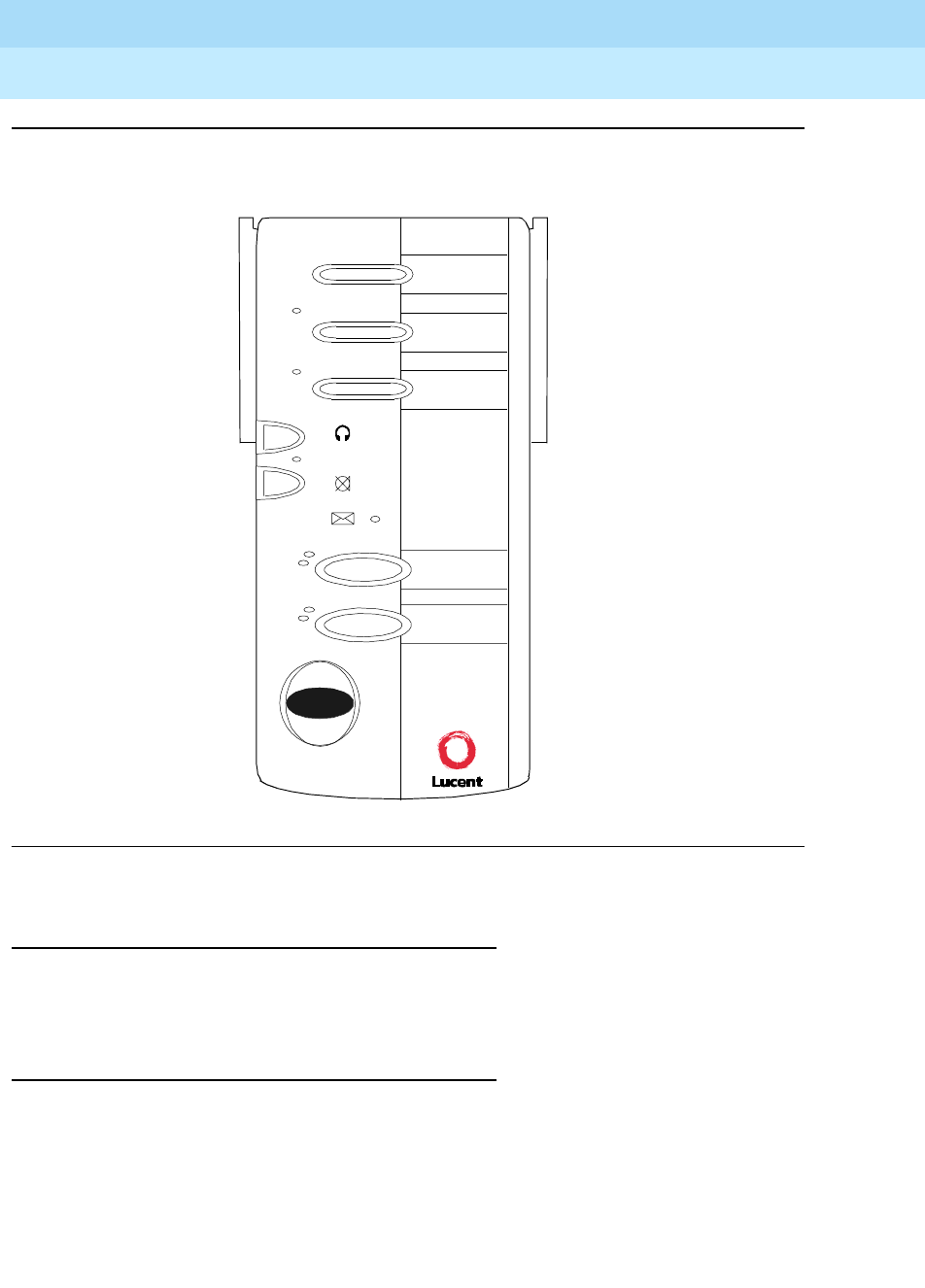
DEFINITYEnterpriseCommunicationsServerandSystem75andSystem85
Terminals and Adjuncts Reference
555-015-201 Issue 11
December 1999
CALLMASTER Voice Terminals
13-24
13
Figure 13-11. Button Numbering for Administering the CALLMASTER IV Voice
Terminal Connected to a DEFINITY ECS G3 Release 6.1 or Later
Power Failure Operation
The CALLMASTER voice terminals cannot be used as an emergency station
during power failure transfer conditions.
FCC Registration
The CALLMASTER voice terminals are not FCC registered.
CALLMASTER VI
Headset On / Off
Mute
Message
a=
b=
Release
1
2
3
6
7
8
9

DEFINITYEnterpriseCommunicationsServerandSystem75andSystem85
Terminals and Adjuncts Reference
555-015-201 Issue 11
December 1999
CALLMASTER Voice Terminals
13-25
13
CALLMASTER Equipment PECs and Comcodes
The CALLMASTER voice terminals and optional components can be ordered with
the following PECs and Comcodes:
■Basic 602A1 CALLMASTER Voice Terminal
Black—3179-001 CLR03
Misty cream—3179-001 CLR22
■Basic 602D1 CALLMASTER Voice Terminal
Black—3179-002 CLR03
Misty cream—3179-002 CLR22
■Basic CALLMASTER II Voice Terminal with Recorder Interface
Black—3179-102 CLR03; Comcode: 106693294
Misty cream—3179-102 CLR22; Comcode: 106693302
White—3179-102 CLR10; Comcode: 107316960
■Basic CALLMASTER III Voice Terminal without Recorder Interface
Black—3179-103 CLR03; Comcode: 107316978
Misty cream—3179-103 CLR22; Comcode: 107316994
White—3179-103 CLR10; Comcode: 107316986
■Basic CALLMASTER IV Voice Terminal with Recorder Interface
Black—3179-40B CLR03; Comcode: 108010554
Misty cream—3179-40M CLR22; Comcode: 108010570
White—3179-40W CLR10; Comcode: 108010562
■Basic CALLMASTER V Telephone Console (Gray only)
Standard English label set — PEC: 3179-50G, Comcode: 108409251
Icon-labeled set — PEC: 3179-5GG, Comcode: 108409263
■Basic CALLMASTER VI Voice Terminal
International gray— 8315-C10; Comcode: 107837544
■EIA cable (5 feet, 9-pin, M-M) (for CALLMASTER VI)
Comcode: 848037743
■CentreVu Agent Callbar software CD ROM (for CALLMASTER VI)
Comcode: 108090457
■Button Designation Strips (for CALLMASTER II and III)
Package of 25 (silver): 846753099
Package of 25 (international gray): 846953115
Package of 200 (silver): 846953107
Package of 200 (international gray): 846953123
■Designation cards (for CALLMASTER IV)
Package of 25: 847933850
■Designation cards (8-1/2” by 11”) (for CALLMASTER V)
Package of 25: 847991650
■Designation cards (for CALLMASTER VI)
Package of 25: 847948056

DEFINITYEnterpriseCommunicationsServerandSystem75andSystem85
Terminals and Adjuncts Reference
555-015-201 Issue 11
December 1999
CALLMASTER Voice Terminals
13-26
13
■Designation card covers (for CALLMASTER V)
Package of 25: 108272402
■Notepad covers (for CALLMASTER V)
Package of 25: 108573304
■Notepads (with 9 Notepads per sheet – 8-1/2” x 11”)
Package of 25: 108562570
■Velcro strips (for CALLMASTER VI)
Package of 25: 847976479
■Handset D-Kit #182083 (black, for CALLMASTER II, CALLMASTER III,
and CALLMASTER IV)
Comcode: 105514798
■Handset D-Kit #182084 (misty cream, for CALLMASTER II,
CALLMASTER III, and CALLMASTER IV)
Comcode: 105514806
■Handset D-Kit #182835 (white, for CALLMASTER II, CALLMASTER III,
and CALLMASTER IV)
Comcode: 107318438
■Handset D-Kit (gray, for CALLMASTER V)
PEC 31293 & 31293A,
Comcode 407904309).
■A pull-out tray with five quick reference cards (for CALLMASTER V)
the tray = PEC: 33111, Comcode: 108272584;
the cards: Comcode: 108032178).
■XM24 Expansion Module (with a new base angle for the 6416D+M,
6424D+M, and CALLMASTER V)
Gray XM24 = PEC: 33071/A, Comcode: 108544511
■Kneewell Adapter (for 602 CALLMASTER)—31791
■Headsets—(See PEC 3122 for carbon compatible types)
Adjuncts
The following adjunct can be used with the 602, the CALLMASTER II,
CALLMASTER III, and CALLMASTER IV voice terminals:
■7400B Plus Data Module
The following adjuncts can be used with the CALLMASTER II, CALLMASTER III,
and CALLMASTER IV:
■S101A and 201A Speakerphone
■507A Adapter
■500A Headset Adapter (and a standard headset; see “Headsets” below)

DEFINITYEnterpriseCommunicationsServerandSystem75andSystem85
Terminals and Adjuncts Reference
555-015-201 Issue 11
December 1999
CALLMASTER Voice Terminals
13-27
13
Headsets
A list of compatible headsets, consisting of both modular and plug prong base
units and selection of headpieces, appears in “Headset Adapters” in the Adjuncts
section later in this manual.
Additional Documents
The following documents contain additional information relating to the
CALLMASTER voice terminals:
■
DEFINITY Generic 2 and System 85 CALLMASTER Voice Terminal User’s
Guide
, 555-015-716
■
DEFINITY CALLMASTER II and CALLMASTER III Voice Terminal User
and Installation Instructions
, 555-015-168
■
DEFINITY CALLMASTER IV Voice Terminal User and Installation
Instructions
, 555-015-171
■
DEFINITY CALLMASTER II, CALLMASTER III, and CALLMASTER IV
Instructions for Programming the Options
, 555-015-172
■
CALLMASTER V Telephone Console User’s Guide
, 555-233-735
■
CALLMASTER VI Voice Terminal Version 1.0 Installation and User’s
Manual
, 555-015-162
■
CentreVu Agent Version 1.1 Installation and Administration
, 585-215-815
■
DEFINITY Generic 1 and Generic 3 Automatic Call Distribution (ACD)
Agent Instructions
, 555-230-722
■
DEFINITY Generic 1 and Generic 3 Automatic Call Distribution (ACD)
Supervisor Instructions
, 555-204-724

DEFINITYEnterpriseCommunicationsServerandSystem75andSystem85
Terminals and Adjuncts Reference
555-015-201 Issue 11
December 1999
CALLMASTER Voice Terminals
13-28
13

The 500 and 2500 Series Telephones
14-1
14
DEFINITYEnterpriseCommunicationsServerandSystem75andSystem85
Terminals and Adjuncts Reference
555-015-201 Issue 11
December 1999
14
The 500 and 2500 Series Telephones
The following 500 and 2500 Series Telephones are described in this section:
■500-Series telephone
■2500 DMGC telephone
■2500 YMGK telephone
■2500 MMGL, 2500 MMGM, 2500 YMGL, and 2500 YMGM telephones
■2554 MMGM and 2554 YMGM telephones
■2500 MMGN and 2500 YMGP telephones
■2554 MMGN and 2554 YMGP telephones
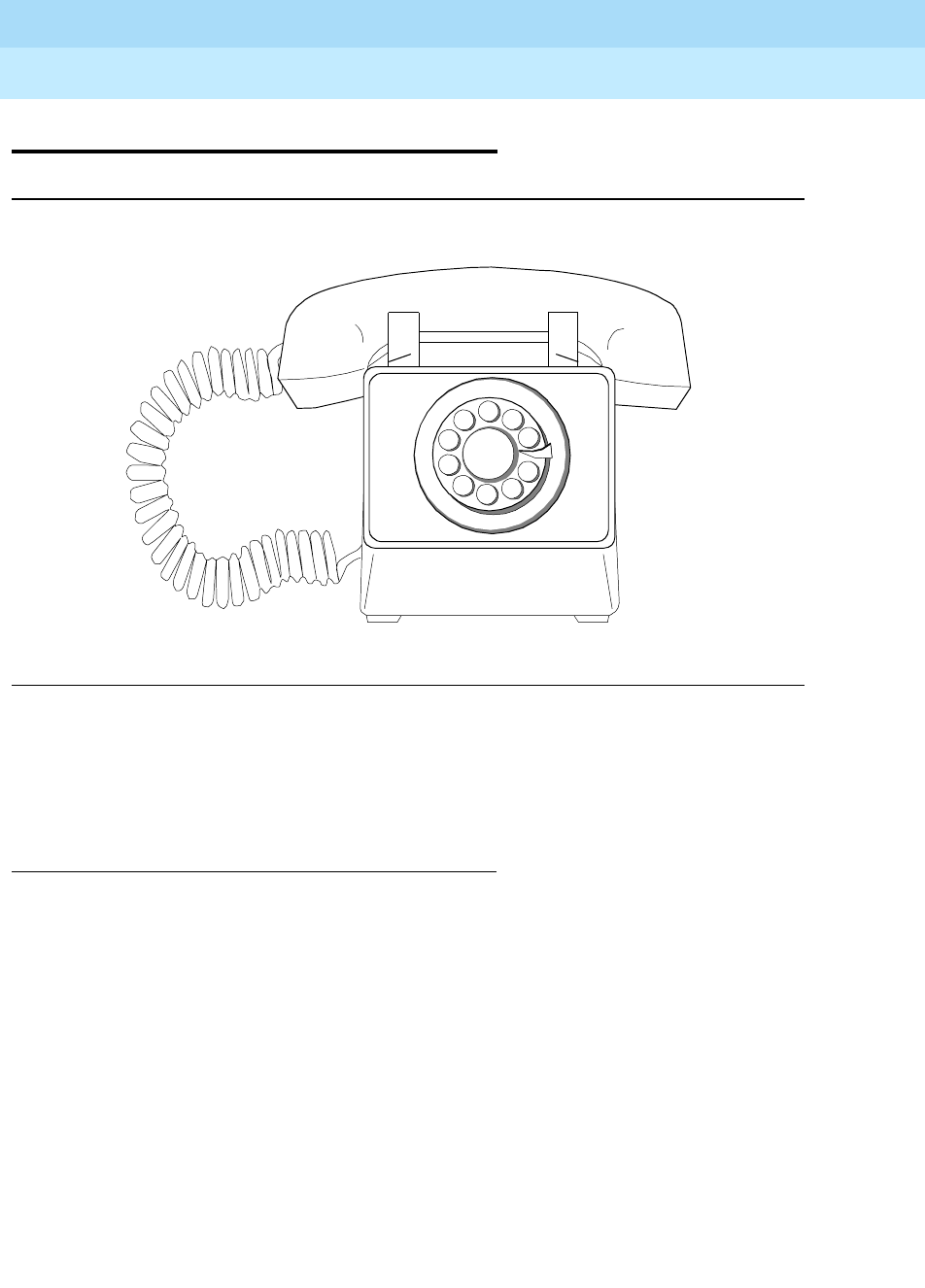
DEFINITYEnterpriseCommunicationsServerandSystem75andSystem85
Terminals and Adjuncts Reference
555-015-201 Issue 11
December 1999
The 500 and 2500 Series Telephones
14-2The 500 Series Telephone
14
The 500 Series Telephone
Figure 14-1. The 500 Series Telephone
The 500 telephone is a single appearance analog rotary dial telephone which
provides cost-effective service wherever it is located. However, note that it
provides limited access to features because the rotary dial has no * or # positions.
Applications
The 500 telephone can be used with the DEFINITY Communications System
Generic 1, Generic 2, and Generic 3, the DEFINITY ECS, System 75, and
System 85. This telephone is especially suitable for manufacturing, warehousing,
guard stations, or power failure locations.

DEFINITYEnterpriseCommunicationsServerandSystem75andSystem85
Terminals and Adjuncts Reference
555-015-201 Issue 11
December 1999
The 500 and 2500 Series Telephones
14-3The 500 Series Telephone
14
Physical Description
Dimensions
NOTE:
The following dimensions are approximate.
Width = 7 inches
Depth (front to back) = 8-3/4 inches
Height (maximum with handset in place) = 5-1/2 inches
Physical Features
Handset
The 500 telephone is equipped with a G-type handset.
Dial pad
The 500 telephone has a 10-hole rotary dial.
Jacks
The 500 telephone housing contains two jacks. The handset cord jack is on the
left side of the telephone. The line jack is on the back of the telephone. The
handset contains a jack for the handset cord.
Cords
Two cords are supplied with the 500 telephone: a coiled 7-foot modular handset
cord and a 7-foot modular line cord. Optional longer cords are available: a 12-foot
handset cord, and 14-foot and 25-foot line cords.
Ringing
The 500 telephone has a mechanical bell type ringer. The volume control is on the
bottom of the telephone.
Mounting Options
The 500 telephone can be desk mounted only.
Color Options
The 500 telephone is available in ivory, black, and beige.
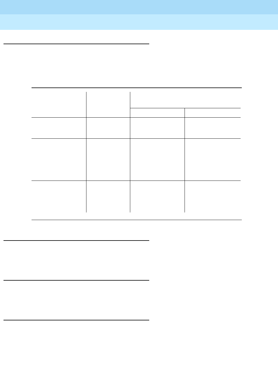
DEFINITYEnterpriseCommunicationsServerandSystem75andSystem85
Terminals and Adjuncts Reference
555-015-201 Issue 11
December 1999
The 500 and 2500 Series Telephones
14-4The 500 Series Telephone
14
Distance Limitations
The maximum allowable distances of a 500 telephone from the DEFINITY G1, G2,
and G3, DEFINITY ECS, System 75, or System 85 cabinet are shown in the table
below.
Power Requirements
The 500 telephone is powered by the tip and ring leads. It does not require any
external power supply.
Power Failure Operation
The 500 telephone can be used as an emergency station during power failure
transfer conditions.
FCC Registration
The 500 telephone is FCC registered.
Table 14-1. Distance Limitations for the 500 Telephone
System Port Board
Nominal Maximum Range in Feet
(Meters)
24 AWG 26 AWG
System 85 SN229
SN228B
3,500 (1,067)
15,000 (4,572)
3,500 (1,067)
9,000 (2,743)
DEFINITY G2 SN229
SN228B
TN742
TN746
3,500 (1,067)
15,000 (4,572)
20,000 (6,100)
3,100 (945)
3,500 (1,067)
9,000 (2,743)
13,000 (3,962)
2,000 (610)
DEFINITY G1 and
G3, DEFINITY
ECS, and System
75
TN742
TN769
TN746
20,000 (6,100)
20,000 (6,100)
3,100 (945)
13,000 (3,962)
13,000 (3,962)
2,000 (610)

DEFINITYEnterpriseCommunicationsServerandSystem75andSystem85
Terminals and Adjuncts Reference
555-015-201 Issue 11
December 1999
The 500 and 2500 Series Telephones
14-5The 500 Series Telephone
14
500-Series Telephone Equipment PECs
The 500 telephone and optional components can be ordered with the following
PECs:
■Basic 500 Telephone (black) — 3100-0RD COL09
■Basic 500 Telephone (beige) — 3100-0RD COL11
■Basic 500 Telephone for use with the 4A speakerphone (black) —
3100-2RD COL09
■Basic 500 Telephone for use with the 4A speakerphone (beige) —
3100-0RD COL11
■Handset cord (12 feet, black) — 2725-01L COL09
■Line cord (14 feet, silver) — 2725-07N COL18
■Line cord (25 feet, silver) — 2725-07S COL18
Adjuncts
The following adjuncts can be used with the optional 500SM telephone:
■4A Speakerphone
■Z34A-WA Message Waiting Indicator
Additional Documents
The following documents contain additional information relating
to the 500 telephone:
■
DEFINITY Generic 1 and Generic 2, System 75, and System 85 Terminals
and Adjuncts Installation and Test
, 555-015-104
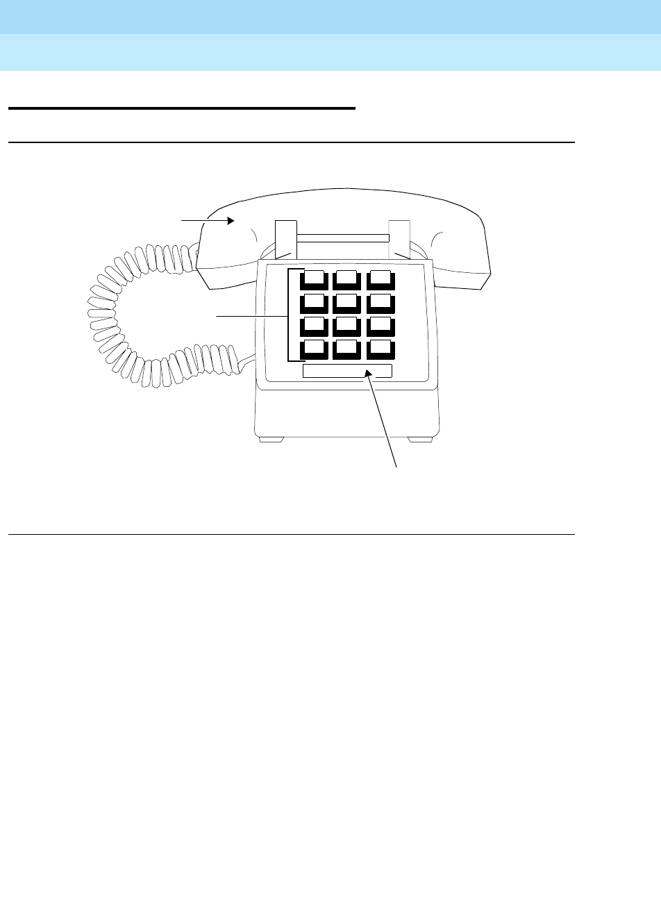
DEFINITYEnterpriseCommunicationsServerandSystem75andSystem85
Terminals and Adjuncts Reference
555-015-201 Issue 11
December 1999
The 500 and 2500 Series Telephones
14-6The 2500 Series Telephones
14
The 2500 Series Telephones
Figure 14-2. The 2500 Desk Model
Handset
123
456
78 9
ABC DEF
MNOJKLGHI
PQRS TUV WXYZ
*
O#
Oper
Telephone
Number Card
Dial Pad
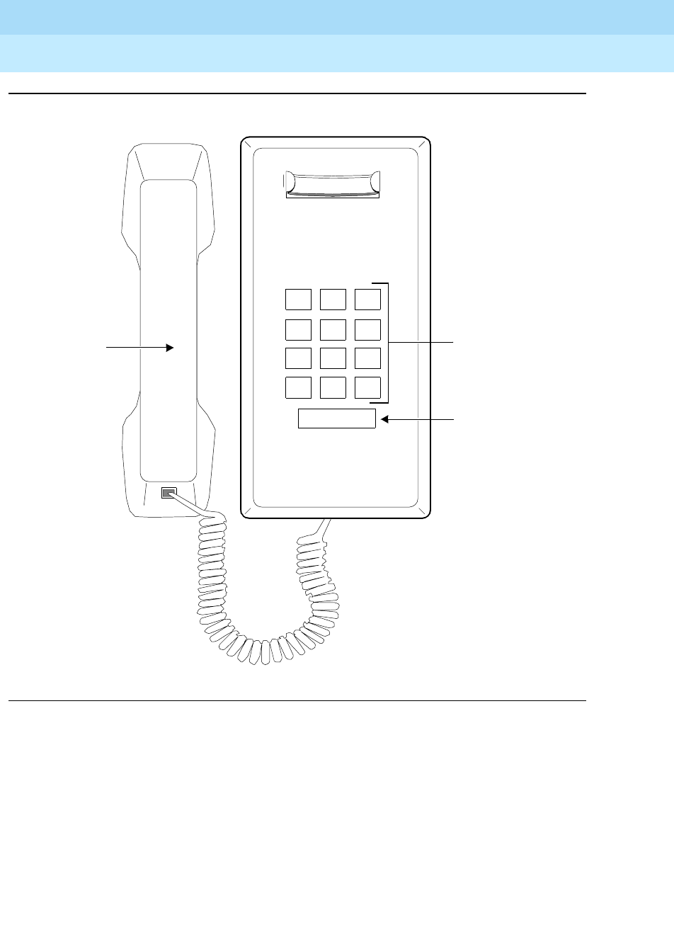
DEFINITYEnterpriseCommunicationsServerandSystem75andSystem85
Terminals and Adjuncts Reference
555-015-201 Issue 11
December 1999
The 500 and 2500 Series Telephones
14-7The 2500 Series Telephones
14
Figure 14-3. The 2554 Wall Model
Dial Pad
123
456
789
ABC DEF
MNOJKLGHI
PRS TUV WXY
*
O#
Oper
Telephone
Number Card
Handset
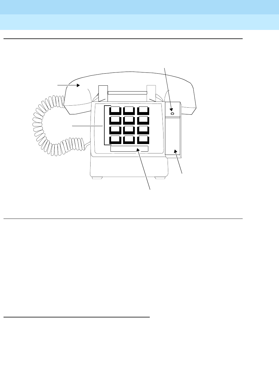
DEFINITYEnterpriseCommunicationsServerandSystem75andSystem85
Terminals and Adjuncts Reference
555-015-201 Issue 11
December 1999
The 500 and 2500 Series Telephones
14-8The 2500 Series Telephones
14
Figure 14-4. The 2500 Telephone with Message Waiting Adjunct
The 2500 Series telephones consist of single appearance analog telephones with
conventional touch-tone dialing. These telephones provide access to features
through the use of the * or # dial pad keys and the appropriate feature access
codes.
The 2500 Series telephones are made up of several telephones that are basically
the same but are equipped with small different attributes. The 2500 DMGC,
2500 YMGK, 2500 MMGL, 2500 MMGM, 2500 YMGL, and the 2500 YMGM are
covered in separate sections of this chapter; all the others are covered here.
Applications
The 2500 Series telephones can be used with the DEFINITY Communications
System Generic 1, Generic 2, and Generic 3, the DEFINITY ECS, System 75, and
System 85. This telephone is especially suitable for manufacturing, warehousing,
guard stations, or power failure locations.
Handset
123
456
78 9
ABC DEF
MNOJKLGHI
PQRS TUV WXYZ
*
O#
Oper
Telephone
Number Card
Dial Pad
Message
Message
Waiting Light
Waiting Adjunct

DEFINITYEnterpriseCommunicationsServerandSystem75andSystem85
Terminals and Adjuncts Reference
555-015-201 Issue 11
December 1999
The 500 and 2500 Series Telephones
14-9The 2500 Series Telephones
14
Physical Description
Dimensions
NOTE:
The following dimensions are approximate.
Width = 7 inches
Depth (front to back) = 8-3/4 inches
Height (maximum with handset in place) = 5-1/2 inches
Features
RECALL button
The 2500 MMGK is equipped with a Timed Recall button. This button provides
access to a second dial tone (if provided) without disconnecting the first call.
Other Physical Features
Handset
Most 2500 Series telephones are equipped with a G-type handset; however, some
newer versions have the hearing aid compatible K-type handset.
Dial pad
The 2500 Series telephone is equipped with a 12-button touch-tone dial pad.
Jacks
The 2500 Series telephone housing contains two jacks. The handset cord jack is
on the left side of the telephone. The line cord jack is on the back of the telephone.
The handset contains a jack for the handset cord. The 2514 CM contains a jack
for optional equipment.
Cords
Two cords are supplied with the 2500 Series telephone: a coiled 7-foot modular
handset cord and a 7-foot modular line cord. Optional longer cords are available:
a 12-foot handset cord, and 14-foot and 25-foot line cords.
Ringing
The 2500 Series telephone has a bell type ringer. The volume control on the desk
set is located on the bottom of the telephone. The volume control on the
wall-mounted set is located on the upper right side of the telephone.

DEFINITYEnterpriseCommunicationsServerandSystem75andSystem85
Terminals and Adjuncts Reference
555-015-201 Issue 11
December 1999
The 500 and 2500 Series Telephones
14-10The 2500 Series Telephones
14
Mounting Options
The 2500 Series telephones are all desk mounted with the exception of the
2554 MMGJ which is wall-mounted only.
Color Options
The 2500 Series telephones are available in several colors.
■The 2500 MMGJ telephone is available in black, beige, and ivory.
■The 2500 MGK telephone is available in black and misty cream.
■The 2554 MMGJ telephone is available in black and misty cream.
■The 2500 SM telephone is available in black, beige, and ivory.
■The 2504 CM telephone is available only in ivory.
■The 2514 CM Telephone is available in black, beige, and ivory.
Distance Limitations
The maximum allowable distances of a 2500 Series telephone from the DEFINITY
G1, G2, and G3, DEFINITY ECS, System 75, or System 85 cabinet are shown in
the table below.
Table 14-2. Distance Limitations for the 2500-Series Telephones
System Port Board
Nominal Maximum Range in Feet
(Meters)
24 AWG 26 AWG
System 85 SN229
SN228B
3,500 (1,067)
15,000 (4,572)
3,500 (1,067)
9,000 (2,743)
DEFINITY G2 SN229
SN228B
TN742
TN746
3,500 (1,067)
15,000 (4,572)
20,000 (6,100)
3,100 (945)
3,500 (1,067)
9,000 (2,743)
13,000 (3,962)
2,000 (610)
DEFINITY G1 and
G3, DEFINITY
ECS, and System
75
TN742
TN769
TN746
20,000 (6,100)
20,000 (6,100)
3,100 (945)
13,000 (3,962)
13,000 (3,962)
2,000 (610)

DEFINITYEnterpriseCommunicationsServerandSystem75andSystem85
Terminals and Adjuncts Reference
555-015-201 Issue 11
December 1999
The 500 and 2500 Series Telephones
14-11The 2500 Series Telephones
14
Power Requirements
The 2500 Series telephone is powered by the tip and ring leads. It does not
require any external power supply.
Power Failure Operation
The 2500 Series telephone can be used as an emergency station during power
failure transfer conditions.
FCC Registration
The 2500 Series telephone is FCC registered.
2500-Series Telephone Equipment PECs
The 2500 Series Voice Terminals and optional components can be ordered with
the following PECs:
■2500 MMGJ Basic Telephone (black) — 3101-EDB COL09
■2500 MMGJ Basic Telephone (beige) — 3101-EDB COL11
■2500 MMGJ Basic Telephone (ivory) — 3101-EDB COL12
■2500 MGK Basic Telephone (black) — 3101-ETR COL09
■2500 MGK Basic Telephone (misty cream) — 3101-ETR COL22
■2554 MMGJ Basic Telephone (black) — 3101-EMW COL09
■2554 MMGJ Basic Telephone (misty cream) — 3101-EMW COL09
■2500 SM Basic Telephone (black) — 3101-2TD COL09
■2500 SM Basic Telephone (beige) — 3101-2TD COL11
■2500 SM Basic Telephone (ivory) — 3101-2TD COL12
■2504 CM Basic Telephone (ivory) — 3100-T4W
■2514 CM Basic Telephone (black) — 3100-TJE COL09
■2514 CM Basic Telephone (beige) — 3100-TJE COL11
■2514 CM Basic Telephone (ivory) — 3100-TJE COL12
■Handset cord (12 feet, black) — 2725-01L COL09
■Line cord (14 feet, silver) — 2725-07N COL18
■Line cord (25 feet, silver) — 2725-07S COL18

DEFINITYEnterpriseCommunicationsServerandSystem75andSystem85
Terminals and Adjuncts Reference
555-015-201 Issue 11
December 1999
The 500 and 2500 Series Telephones
14-12The 2500 Series Telephones
14
Adjuncts
The following adjuncts can be used with the optional 2500 SM telephone:
■4A Speakerphone
■Z34A-WA Message Waiting Indicator
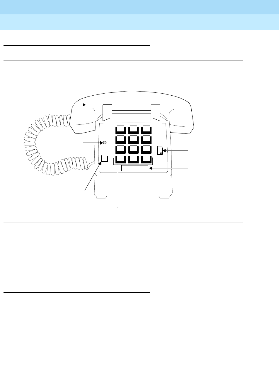
DEFINITYEnterpriseCommunicationsServerandSystem75andSystem85
Terminals and Adjuncts Reference
555-015-201 Issue 11
December 1999
The 500 and 2500 Series Telephones
14-13The 2500 DMGC Telephone
14
The 2500 DMGC Telephone
Figure 14-5. The 2500 DMGC Telephone
The 2500 DMGC telephone is a single appearance analog telephone with
conventional touch-tone dialing. It provides access to features through the use of
the * or # dial pad keys and the appropriate feature access codes. The
2500 DMGC telephone is equipped with a RECALL button, Message Waiting light,
and a 3-position volume control.
Applications
The 2500 DMGC telephone can be used with the DEFINITY Communications
System Generic 1, Generic 2, and Generic 3, the DEFINITY ECS, System 75, and
System 85. This telephone is especially suitable for manufacturing, warehousing,
guard stations, or power failure locations.
Handset
Telephone
Number Card
Message Waiting
123
456
789
ABC DEF
MNOJKLGHI
PQRS TUV WXYZ
*
O#
Oper
R
Dial Pad
Light
Recall (R)
Button
Volume
Control

DEFINITYEnterpriseCommunicationsServerandSystem75andSystem85
Terminals and Adjuncts Reference
555-015-201 Issue 11
December 1999
The 500 and 2500 Series Telephones
14-14The 2500 DMGC Telephone
14
Physical Description
Dimensions
NOTE:
The following dimensions are approximate.
Width = 7 inches
Depth (front to back) = 8-3/4 inches
Height (maximum with handset in place) = 5-1/2 inches
Features
RECALL button
The RECALL button performs the same function as flashing the switchhook.
Message light
The red Message light blinks when you have a message.
Other Physical Features
Handset
The 2500 DMGC telephone is equipped with a G-type handset.
Dial pad
The 2500 DMGC telephone has a 12-button touch-tone dial pad.
Jacks
The 2500 DMGC telephone housing contains two jacks. The handset cord jack is
on the left side of the telephone. (The handset contains a jack for the other end of
the handset cord.) The line jack is on the back of the telephone.
Cords
Two cords are supplied with the 2500 DMGC telephone: a coiled 7-foot modular
handset cord and a 7-foot modular line cord. Optional longer cords are available:
a 12-foot handset cord, and 14-foot and 25-foot line cords.
Ringing
The 2500 DMGC has electronic tone ringing. The 3-position volume control is
located on the faceplate of the telephone.
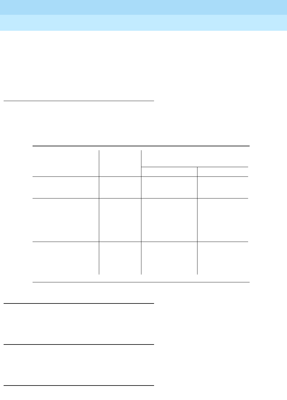
DEFINITYEnterpriseCommunicationsServerandSystem75andSystem85
Terminals and Adjuncts Reference
555-015-201 Issue 11
December 1999
The 500 and 2500 Series Telephones
14-15The 2500 DMGC Telephone
14
Mounting Options
The 2500 DMGC telephone can only be desk-mounted.
Color Options
The 2500 DMGC telephone is available in black or ivory.
Distance Limitations
The maximum allowable distances of a 2500 DMGC telephone from the
DEFINITY G1, G2, and G3, DEFINITY ECS, System 75, or System 85 cabinet are
shown in the table below.
Power Requirements
The 2500 DMGC telephone is powered by the tip and ring leads. It does not
require any external power supply.
Power Failure Operation
The 2500 DMGC telephone can be used as an emergency station during power
failure transfer conditions.
FCC Registration
The 2500 DMGC telephone is FCC registered.
Table 14-3. Distance Limitations for the 2500 DMGC Telephone
System Port Board
Nominal Maximum Range in Feet
(Meters)
24 AWG 26 AWG
System 85 SN229
SN228B
3,500 (1,067)
15,000 (4,572)
3,500 (1,067)
9,000 (2,743)
DEFINITY G2 SN229
SN228B
TN742
TN746
3,500 (1,067)
15,000 (4,572)
20,000 (6,100)
3,100 (945)
3,500 (1,067)
9,000 (2,743)
13,000 (3,962)
2,000 (610)
DEFINITY G1
and G3,
DEFINITY ECS,
and System 75
TN742
TN769
TN746
20,000 (6,100)
20,000 (6,100)
3,100 (945)
13,000 (3,962)
13,000 (3,962)
2,000 (610)

DEFINITYEnterpriseCommunicationsServerandSystem75andSystem85
Terminals and Adjuncts Reference
555-015-201 Issue 11
December 1999
The 500 and 2500 Series Telephones
14-16The 2500 DMGC Telephone
14
2500 DMGC Equipment PECs
The 2500 DMGC Voice Terminals and optional components can be ordered with
the following PECs:
■2500 DMGC Basic Telephone (black) — 3178-SYSB
■2500 DMGC Basic Telephone (ivory) — 3178-SYSI
■Handset cord (12 feet, black) — 2725-01L COL09
■Line cord (14 feet, silver) — 2725-07N COL18
■Line cord (25 feet, silver) — 2725-07S COL18
Adjuncts
The 2500 DMGC telephone is not compatible with any adjuncts.
Additional Documents
The following documents contain additional information relating to the
2500 DMGC telephone:
■
DEFINITY Generic 1 and Generic 2, System 75, and System 85 Terminals
and Adjuncts Installation and Test
, 555-015-104
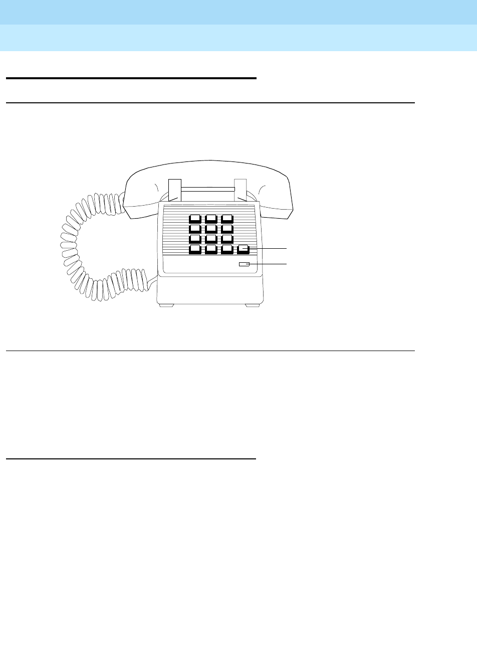
DEFINITYEnterpriseCommunicationsServerandSystem75andSystem85
Terminals and Adjuncts Reference
555-015-201 Issue 11
December 1999
The 500 and 2500 Series Telephones
14-17The 2500 YMGK Telephone
14
The 2500 YMGK Telephone
Figure 14-6. The 2500 YMGK Telephone
The 2500 YMGK telephone is a single appearance analog telephones with
conventional touch-tone dialing. It is equipped with a RECALL button and a
Message Waiting light. It provides access to features through the use of the * or #
dial pad keys and the appropriate feature access codes.
Applications
The 2500 YMGK telephone can be used with the DEFINITY Communications
System Generic 1, Generic 2, and Generic 3, the DEFINITY ECS, System 75, and
System 85. This telephone is especially suitable for manufacturing, warehousing,
guard stations, or power failure locations.
Message Light
Recall Button

DEFINITYEnterpriseCommunicationsServerandSystem75andSystem85
Terminals and Adjuncts Reference
555-015-201 Issue 11
December 1999
The 500 and 2500 Series Telephones
14-18The 2500 YMGK Telephone
14
Physical Description
Dimensions
NOTE:
The following dimensions for the 2500 YMGK telephone are approximate.
Width = 7 inches
Depth (front to back) = 8-3/4 inches
Height (maximum with handset in place) = 5-1/2 inches
Features
RECALL button
The RECALL button performs the same function as flashing the switchhook.
Message light
The red Message light flashes when a message has been left, and flutters when a
call is being received.
Other Physical Features
Handset
The 2500 YMGK telephone is equipped with a K-type handset.
Dial Pad
The 2500 YMGK telephone has a 12-button touch-tone dial pad.
Jacks
The 2500 YMGK telephone housing contains two jacks. The handset cord jack is
on the left side of the telephone. (The handset contains a jack for the other end of
the handset cord.) The line jack is on the back of the telephone.
Cords
Two cords are supplied with the 2500 YMGK telephone: a coiled 7-foot modular
handset cord and a 7-foot modular line cord. Optional longer cords are available:
a 12-foot handset cord, and 14-foot and 25-foot line cords.

DEFINITYEnterpriseCommunicationsServerandSystem75andSystem85
Terminals and Adjuncts Reference
555-015-201 Issue 11
December 1999
The 500 and 2500 Series Telephones
14-19The 2500 YMGK Telephone
14
Ringing
The 2500 YMGK telephone has electronic tone ringer. The volume control is
located on the bottom of the telephone.
Mounting Options
The 2500 YMGK telephone is desk-mounted.
Color Options
The 2500 YMGK telephone is available in black or misty cream.
Distance Limitations
The maximum allowable distances of a 2500 YMGK telephone from the
DEFINITY G1, G2, and G3, DEFINITY ECS, System 75, or System 85 cabinet are
shown in the table below.
Power Requirements
The 2500 YMGK telephone is powered by the tip and ring leads. It does not
require any external power supply.
Table 14-4. Distance Limitations for the 2500 YMGK Telephone
System Port Board
Nominal Maximum Range in Feet
(Meters)
24 AWG 26 AWG
System 85 SN229
SN228B
3,500 (1,067)
15,000 (4,572)
3,500 (1,067)
9,000 (2,743)
DEFINITY G2 SN229
SN228B
TN742
TN746
3,500 (1,067)
15,000 (4,572)
20,000 (6,100)
3,100 (945)
3,500 (1,067)
9,000 (2,743)
13,000 (3,962)
2,000 (610)
DEFINITY G1
and G3,
DEFINITY ECS,
and System 75
TN742
TN769
TN746
20,000 (6,100)
20,000 (6,100)
3,100 (945)
13,000 (3,962)
13,000 (3,962)
2,000 (610)

DEFINITYEnterpriseCommunicationsServerandSystem75andSystem85
Terminals and Adjuncts Reference
555-015-201 Issue 11
December 1999
The 500 and 2500 Series Telephones
14-20The 2500 YMGK Telephone
14
Power Failure Operation
The 2500 YMGK telephone can be used as an emergency station during power
failure transfer conditions.
FCC Registration
The 2500 YMGK telephone’s FCC registration number is AS593M-17899-TE-T.
2500 YMGK Equipment PECs
The 2500 YMGK telephones and optional components can be ordered with the
following PECs:
■2500 YMGK Basic Telephone (black) — 3178-NHL COL003
■2500 YMGK Basic Telephone (misty cream) — 3178-NHL COL022
■Handset cord (12 feet, black) — 2725-01L COL09
■Line cord (14 feet, silver) — 2725-07N COL18
■Line cord (25 feet, silver) — 2725-07S COL18
Adjuncts
The 2500 YMGK telephone is not compatible with any adjuncts.
Additional Documents
The following documents contain additional information relating to
the 2500 YMGK telephone:
■
DEFINITY Generic 1 2500 YMGK User’s Guide
, 555-204-734
■
System 75 2500 YMGK User’s Guide
, 555-200-734
■
DEFINITY Generic 2 and System 85 2500 YMGK User’s Guide
,
555-104-717
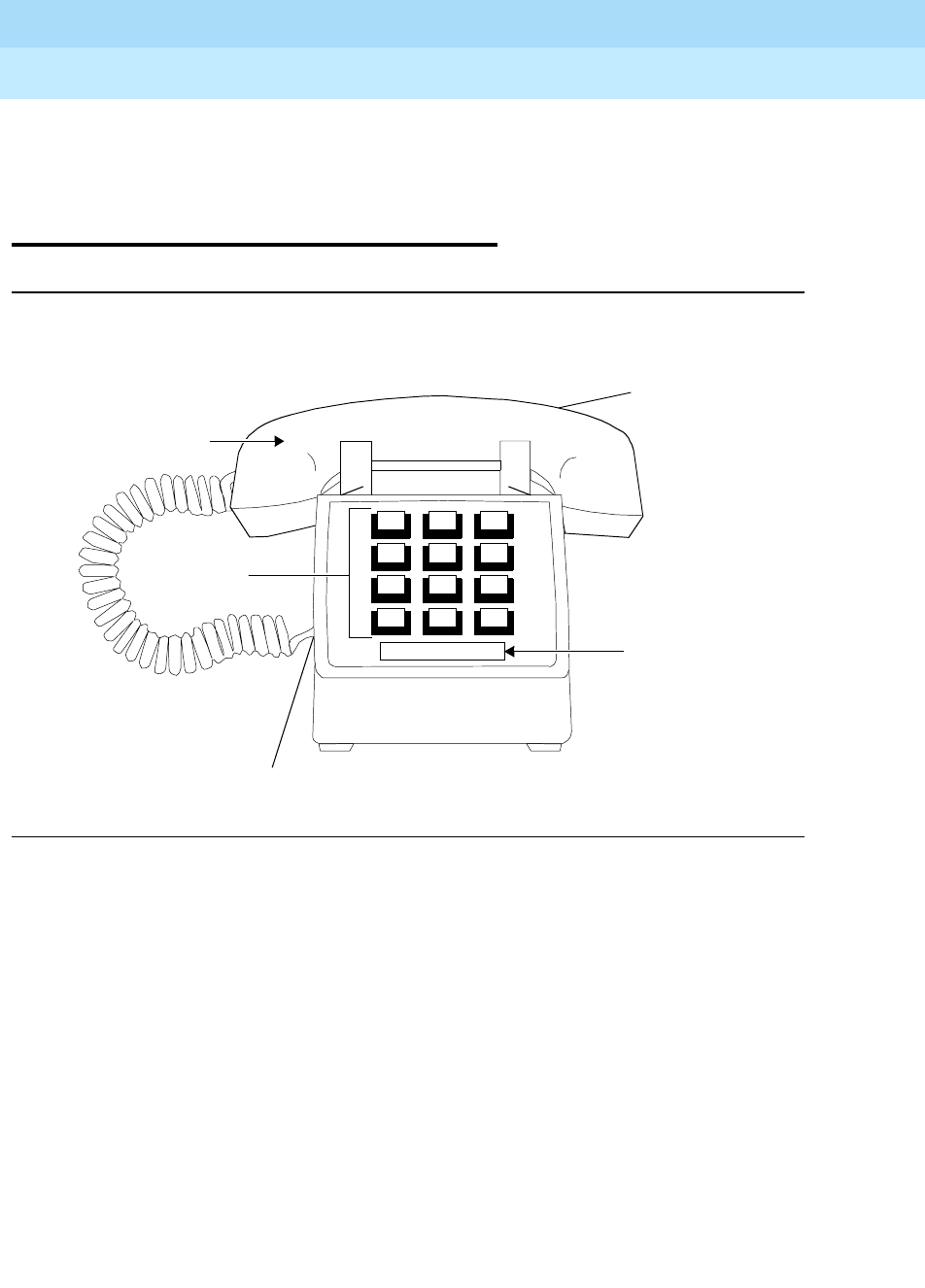
DEFINITYEnterpriseCommunicationsServerandSystem75andSystem85
Terminals and Adjuncts Reference
555-015-201 Issue 11
December 1999
The 500 and 2500 Series Telephones
14-21The 2500 MMGL and 2500 YMGL, 2500 MMGM and 2500 YMGM, and 2554
14
The 2500 MMGL and 2500 YMGL,
2500 MMGM and 2500 YMGM, and
2554 MMGM and 2554 YMGM
Te l ep h o ne s
Figure 14-7. The 2500 MMGL and 2500 MMGM Telephones
Handset
Line Jack
(on back
Telephone
Number Card
Handset Cord Jack
123
456
789
ABC DEF
MNOJKLGHI
PQRS TUV WXYZ
*
O#
Oper
of phone)
Dial Pad
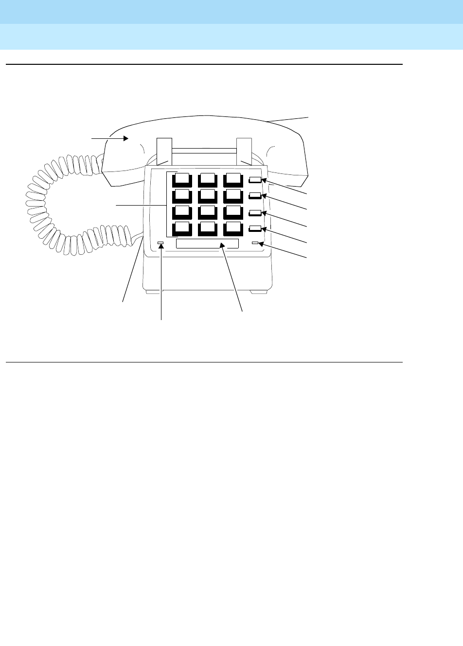
DEFINITYEnterpriseCommunicationsServerandSystem75andSystem85
Terminals and Adjuncts Reference
555-015-201 Issue 11
December 1999
The 500 and 2500 Series Telephones
14-22The 2500 MMGL and 2500 YMGL, 2500 MMGM and 2500 YMGM, and 2554
14
Figure 14-8. The 2500 YMGL and 2500 YMGM Telephones
Handset
Line Jack
(on back of phone)
Handset
Cord Jack
123
456
789
ABC DEF
MNOJKLGHI
PQRS TUV WXYZ
*
O#
Oper
Message Hold
Telephone
Number Card
Message
Light
Mute Button
Flash Button
Redial Button
Hold Button
Hold Light
Mute
Hold
Redial
Flash
Dial Pad
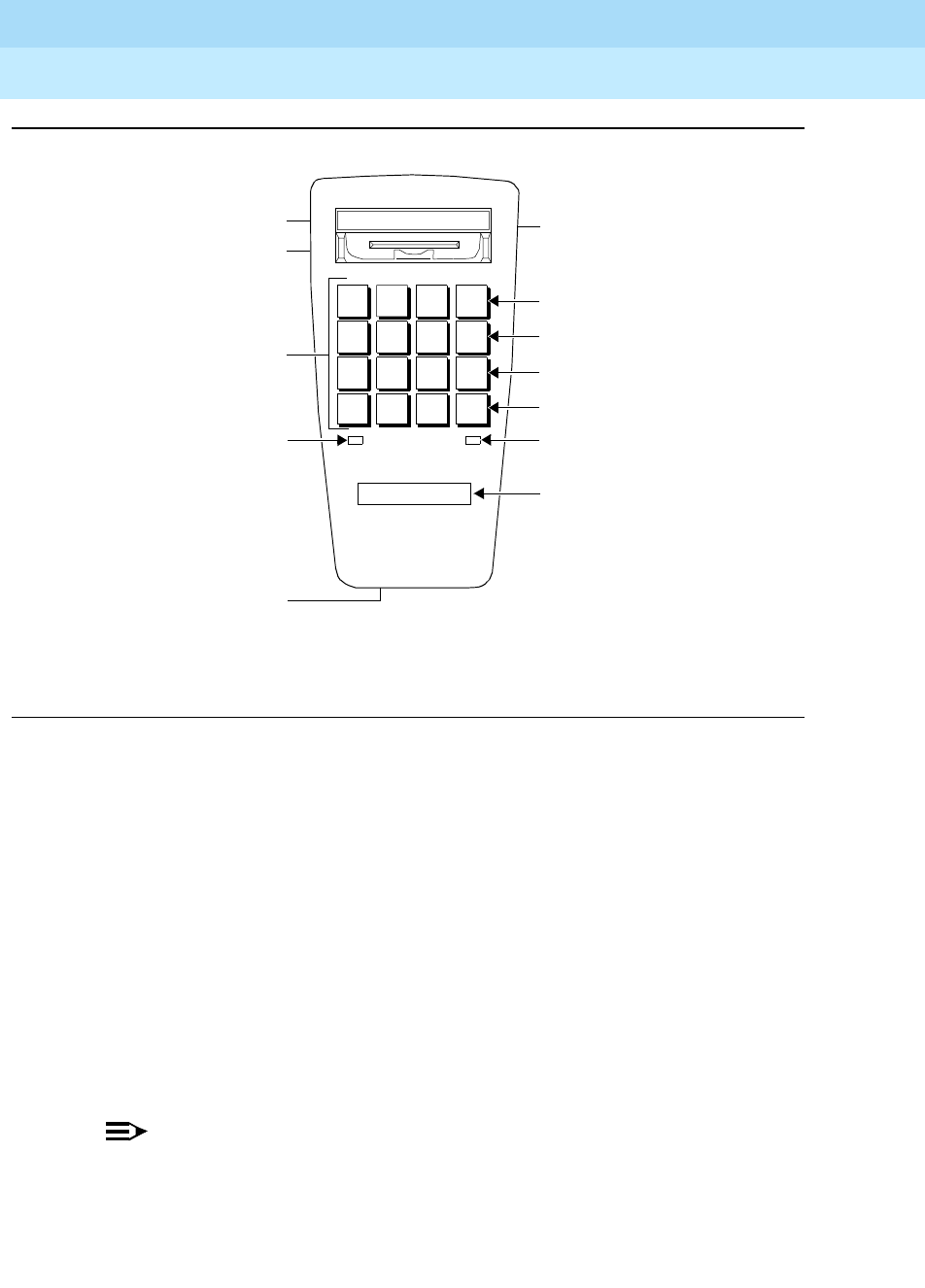
DEFINITYEnterpriseCommunicationsServerandSystem75andSystem85
Terminals and Adjuncts Reference
555-015-201 Issue 11
December 1999
The 500 and 2500 Series Telephones
14-23The 2500 MMGL and 2500 YMGL, 2500 MMGM and 2500 YMGM, and 2554
14
Figure 14-9. The 2554 MMGM and 2554 YMGM Wall-Model Telephones
Like earlier 2500 Series telephones, the 2500 MMGL, 2500 YMGL, 2500 MMGM,
and 2500 YMGM desk model telephones, and the 2554 MMGM and 2554 YMGM
wall model telephones are single appearance analog telephones with
conventional touch-tone dialing. The 2500 MMGL, 2500 MMGM, and
2554 MMGM telephones have NO feature buttons. The 2500 YMGL,
2500 YMGM, and 2554 YMGM telephones are equipped with a FLASH button, a
Message Waiting light, a REDIAL button, a HOLD button, and a MUTE button. All
six of these telephone models provide access to features through the use of the *
or # dial pad keys and the appropriate feature access codes.
On all of these telephones, the user can select either Touch-Tone or Pulse dialing,
whichever is appropriate. There is also a 2-position Positive Disconnect Switch
which ensures faster, cleaner termination of calls when the user presses the
switchhook.
NOTE:
All other 2500 telephones previously available will be manufacture
discontinued beginning in June, 1994. The 2500 MMGL and 2500 YMGL will
be discontinued as of June, 1996, and the 2500 MMGM and 2500 YMGM,
which took their place, will, in turn, be discontinued in December, 1999.
Dial Pad
Telephone
HoldMessage
Message Light**
Number Card
Ringer Volume
Control
Mute Button**
Flash Button**
Redial Button**
Hold Button**
Hold Light**
Tone/Pulse
Switch
Handset Jack
1
4
7
GHI
PQRS
*
2
5
8
ABC
JKL
TUV
O
OPER
DEF
MNO
WXYZ
3
6
9
#
MUTE
FLASH
RE
DIAL
HOLD
Switch*
*
** These five buttons and the Message light appear ONLY on
the 2554 YMGM.
Positive Disconnect

DEFINITYEnterpriseCommunicationsServerandSystem75andSystem85
Terminals and Adjuncts Reference
555-015-201 Issue 11
December 1999
The 500 and 2500 Series Telephones
14-24The 2500 MMGL and 2500 YMGL, 2500 MMGM and 2500 YMGM, and 2554
14
Applications
The 2500 MMGL, 2500 YMGL, 2500 MMGM, 2500 YMGM, 2554 MMGM, and
2554 YMGM telephones can be used with the DEFINITY Communications
System Generic 1, Generic 2, and Generic 3, the DEFINITY ECS, System 75, and
System 85. These 2500 Series telephones are especially suitable for
manufacturing, warehousing, guard stations, or power failure locations.
Physical Description
Dimensions
NOTE:
The following dimensions for the four 2500 desk models are approximate.
Width = 5.37 inches
Depth (front to back) = 9 inches
Height (maximum with handset in place) = 3.81 inches
NOTE:
The following dimensions for the two 2554 wall models are approximate.
Width = 4 inches
Depth (front to back) = 8.5 inches
Height (maximum with handset in place) = 4.5 inches
Features on the 2500 YMGL, 2500 YMGM, and
2554 YMGM Telephones
The 2500 YMGL, 2500 YMGM, and 2554 YMGM telephones have four fixed
feature buttons:
■MUTE button
■FLASH button
■REDIAL button
■HOLD button
MUTE button
Pressing and holding the MUTE button down blocks your conversation from being
heard by the other party.

DEFINITYEnterpriseCommunicationsServerandSystem75andSystem85
Terminals and Adjuncts Reference
555-015-201 Issue 11
December 1999
The 500 and 2500 Series Telephones
14-25The 2500 MMGL and 2500 YMGL, 2500 MMGM and 2500 YMGM, and 2554
14
FLASH button
The FLASH button performs the same function as flashing the switchhook; that is,
it provides access to system features or use of custom calling services that
require a press of the switchhook.
REDIAL button
TheREDIALbuttonisusedtodialthelastnumberdialed(upto28digits).
HOLD button
The HOLD button is used to put a call on hold. Below the HOLD button, there is a
red light. When the user puts a call on hold, the light goes on.
Message light
The red Message light flashes when a message has been left, and flutters when a
call is being received. The telephones recognize either LED or neon message
waiting signals.
Other Physical Features
(on All of these 2500 and 2554 Telephones)
Positive Disconnect
The Positive Disconnect switch on the bottom of the telephone has two positions:
ON and OFF.
■The ON position hangs up the telephone for approximately two seconds,
even if the switchhook depression is less. This prevents inadvertent
switchhook flashes. To initiate switchhook flash in this mode, press the
FLASH button.
■In the OFF position, the switchhook will function normally.
Handset
All of these 2500 Series telephones are equipped with a K-type handset.
Dial Pad
All of these 2500 Series telephones are equipped with a 12-button touch-tone dial
pad. On all telephones, the letters “Q” and “Z” have been added to the appropriate
dial pad keys, and the “5” button on the dial pad has raised bars for
visually-impaired users.
Jacks
All of these 2500 Series telephones contain two jacks. The handset cord jack is on
the left side of the telephone. (The handset also contains a jack for the other end
of the handset cord.) The line cord jack is on the right rear of the set.
DEFINITYEnterpriseCommunicationsServerandSystem75andSystem85
Terminals and Adjuncts Reference
555-015-201 Issue 11
December 1999
The 500 and 2500 Series Telephones
14-26The 2500 MMGL and 2500 YMGL, 2500 MMGM and 2500 YMGM, and 2554
14
Cords
Two cords are supplied with all four of these 2500 Series model telephones: a
coiled 6-foot modular handset cord and a 7-foot modular line cord. Optional longer
cords are available: a 12-foot handset cord, and 14-foot and 25-foot line cords.
Ringing
All of these 2500 Series telephones have an electronic tone ringer. There is a
3-position ringer volume control located on the bottom of the telephone.
Mounting Options
The 2500 MMGL, 2500 MMGM, 2500 YMGL, and 2500 YMGM telephones can
only be desk-mounted. They
cannot
be wall-mounted. The 2554 MMGM and 2554
YMGM telephones are wall model telephones.
Color Options
All of these 2500 Series telephones are available in black or misty cream.
Distance Limitations
The maximum allowable distances of a 2500 telephone from the DEFINITY G1,
G2, and G3, DEFINITY ECS, System 75, or System 85 cabinet are shown in the
table below.
Table 14-5. Distance Limitations for the 2500 MMGL, 2500 YMGL,
2500 MMGM, 2500 YMGM, 2554 MMGM, and 2554 YMGM
Te le p hon e s
System Port Board
Nominal Maximum Range in Feet
(Meters)
24 AWG 26 AWG
SYSTEM 85 SN229
SN228B
3,500 (1,067)
15,000 (4,572)
3,500 (1,067)
9,000 (2,743)
DEFINITY G2 SN229
SN228B
TN742
TN746
TN746B
3,500 (1,067)
15,000 (4,572)
20,000 (6,100)
3,100 (945)
3,100 (945)
3,500 (1,067)
9,000 (2,743)
13,000 (3,962)
2,000 (610)
2,000 (610)
DEFINITY G1 and
G3, DEFINITY
ECS, and System
75
TN742
TN769
TN746
20,000 (6,100)
20,000 (6,100)
3,100 (945)
13,000 (3,962)
13,000 (3,962)
2,000 (610)

DEFINITYEnterpriseCommunicationsServerandSystem75andSystem85
Terminals and Adjuncts Reference
555-015-201 Issue 11
December 1999
The 500 and 2500 Series Telephones
14-27The 2500 MMGL and 2500 YMGL, 2500 MMGM and 2500 YMGM, and 2554
14
Power Requirements
All of these 2500 Series telephones are powered by the tip and ring leads. These
telephones do not require any external power supply.
Switch Administration
These 2500 series telephones must be administered in the following ways:
■If the 2500 MMGL, 2500 YMGL, 2500 MMGM, 2500 YMGM, 2554 MMGM,
or 2554 YMGM telephone is connected to a System 75, DEFINITY G1 or
G3, or a DEFINITY ECS, it must be administered as a 2500 analog
telephone.
■If any of these 2500 Series telephones is connected to a System 85 or a
DEFINITY G2, it can be administered as an analog line.
Power Failure Operation
All of these 2500 Series telephones can be used as an emergency station during
power failure transfer conditions.
FCC Registration
These 2500 telephones are FCC-registered.
UL and CSA Approval
These telephones have been tested and have met the Underwriters Laboratories
(UL) Standards UL 1459 and have also met the Canadian Standards Association
(CSA) Standards CSA-C22.2 No.225-M90.
Hearing Aid Compatible
These telephones are compatible with the inductively coupled hearing aids
prescribed by the FCC.

DEFINITYEnterpriseCommunicationsServerandSystem75andSystem85
Terminals and Adjuncts Reference
555-015-201 Issue 11
December 1999
The 500 and 2500 Series Telephones
14-28The 2500 MMGL and 2500 YMGL, 2500 MMGM and 2500 YMGM, and 2554
14
2500 MMGL and 2500 YMGL Equipment PECs
The 2500 MMGL and 2500 YMGL telephones can no longer be ordered. The
2500 MMGM and 2500 YMGM, and the 2554 MMGM and 2554 YMGM
telephones and optional components can be ordered with the following PECs:
■2500 MMGM Basic Telephone (black) — 3101-KBD COL003
■2500 MMGM Basic Telephone (misty cream) — 3101-KBD COL022
■2500 YMGM Basic Telephone (black) — 3101-KFD COL003
■2500 YMGM Basic Telephone (misty cream) — 3101-KFD COL022
■2554 MMGM Basic Telephone (black) — 3101-KBW COL003
■2554 MMGM Basic Telephone (misty cream —3101-KBW COL022
■2554 YMGM Basic Telephone (black) — 3101-KFW COL003
■2554 YMGM Basic Telephone (misty cream) — 3101-KFW COL022
■Handset cord (12 feet, black) — 2725-01L COL09
■Handset cord (12 feet, misty cream) — 2725-01L COL022
■Line cord (14 feet, silver) — 2725-07N COL18
■Line cord (25 feet, silver) — 2725-07S COL18
Additional Documents
The following document contains additional information relating to the
2500 MMGM and 2500 YMGM telephone, and the 2554 MMGM and 2554 YMGM
telephone: (This document is shipped with these telephones, but is not orderable.)
■
2500 MMGM and 2500 YMGM Telephones, and the 2554 MMGM and
2554 YMGM Telephones Quick Reference Guide
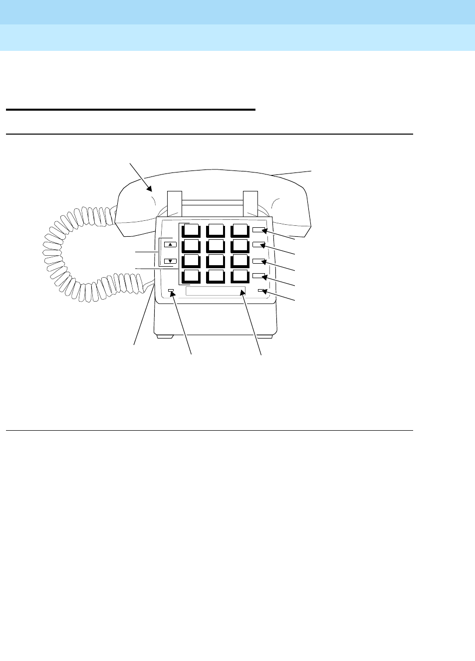
DEFINITYEnterpriseCommunicationsServerandSystem75andSystem85
Terminals and Adjuncts Reference
555-015-201 Issue 11
December 1999
The 500 and 2500 Series Telephones
14-29The 2500 MMGN and 2500 YMGP and 2554 MMGN and 2554 YMGP Telephones
14
The 2500 MMGN and 2500 YMGP and
2554 MMGN and 2554 YMGP
Telephones
Figure 14-10. The 2500 MMGN and 2500 YMGP Telephones
Line Jack
(on back
Handset
Cord Jack
6
Telephone
Light*
of phone)
Mute Button*
Flash Button*
Redial Button*
Hold Button*
Hold Light*
Number Card
Message
Handset
3
#
9
*
1
4
7
2
5
8
O
* These buttons and lights appear ONLY on the 2500 YMGP.
Dial Pad
Handset
Volume Buttons
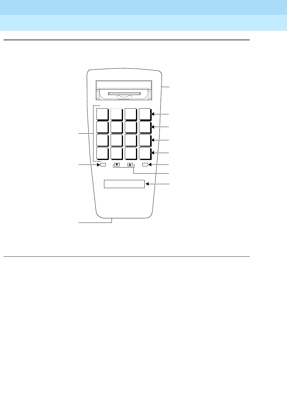
DEFINITYEnterpriseCommunicationsServerandSystem75andSystem85
Terminals and Adjuncts Reference
555-015-201 Issue 11
December 1999
The 500 and 2500 Series Telephones
14-30The 2500 MMGN and 2500 YMGP and 2554 MMGN and 2554 YMGP Telephones
14
Figure 14-11. The 2554 MMGN and 2554 YMGP Wall-Model Telephones
The newest 2500 telephones are the 2500 MMGN and 2500 YMGP desk model
telephones, and the 2554 MMGN and 2554 YMGP wall model telephones. These
models will take the place of the 2500 MMGM, 2500 YMGM, 2554 MMGM, and
2554 YMGM, which will be discontinued as of December 31, 1999.
Like the original 2500 sets, these new 2500 telephones are single appearance
analog telephones with conventional touch-tone dialing.The 2500 MMGN and
2554 MMGN telephones have NO feature buttons. The 2500 YMGP and 2554
YMGP telephones are equipped with a FLASH button, a Message Waiting light, a
REDIAL button, a HOLD button, and a MUTE button. All six of these telephone
models provide access to features through the use of the * or # dial pad keys and
the appropriate feature access codes.
These 2500 Series telephones are automatically set for touch-tone dialing. The
Positive Disconnect feature, which ensures faster, cleaner termination of calls
when the user presses the switchhook, is also set at the factory.
Dial Pad
Telephone
HoldMessage
Message
Number Card
Ringer Volume
Control
Mute Button*
Flash Button*
Redial Button*
Hold Button*
Hold Light*
1
4
7
GHI
PQRS
2
5
8
ABC
JKL
TUV
O
OPER
DEF
MNO
WXYZ
3
6
9
#
MUTE
FLASH
REDIAL
HOLD
* These five buttons and the Message light appear ONLY onthe2554YMGP.
Volume
Volume Buttons
Light*
*
Handset jack

DEFINITYEnterpriseCommunicationsServerandSystem75andSystem85
Terminals and Adjuncts Reference
555-015-201 Issue 11
December 1999
The 500 and 2500 Series Telephones
14-31The 2500 MMGN and 2500 YMGP and 2554 MMGN and 2554 YMGP Telephones
14
Applications
The 2500 MMGN, 2500 YMGP, 2554 MMGN, and 2554 YMGP telephones can be
used with the DEFINITY Communications System Generic 1, Generic 2, and
Generic 3, the DEFINITY ECS, System 75, and System 85. These 2500 Series
telephones are especially suitable for manufacturing, warehousing, guard
stations, or power failure locations.
Physical Description
Dimensions
NOTE:
The following dimensions for the four 2500 desk models are approximate.
Width = 5.37 inches
Depth (front to back) = 9 inches
Height (maximum with handset in place) = 3.81 inches
NOTE:
The following dimensions for the two 2554 wall models are approximate.
Width = 4 inches
Depth (front to back) = 8.5 inches
Height (maximum with handset in place) = 4.5 inches
Features on the 2500 YMGP and 2554 YMGP
Telephones
The 2500 YMGP and 2554 YMGP telephones have four fixed feature buttons:
■MUTE button
■FLASH button
■REDIAL button
■HOLD button
MUTE button
Pressing and holding the MUTE button down blocks your conversation from being
heard by the other party.

DEFINITYEnterpriseCommunicationsServerandSystem75andSystem85
Terminals and Adjuncts Reference
555-015-201 Issue 11
December 1999
The 500 and 2500 Series Telephones
14-32The 2500 MMGN and 2500 YMGP and 2554 MMGN and 2554 YMGP Telephones
14
FLASH button
The FLASH button performs the same function as flashing the switchhook; that is,
it provides access to system features or use of custom calling services that
require a press of the switchhook.
REDIAL button
TheREDIALbuttonisusedtodialthelastnumberdialed(upto28digits).
HOLD button
The HOLD button is used to put a call on hold. Below the HOLD button, there is a
red light. When the user puts a call on hold, the light goes on.
Message light
The red Message light flashes when a message has been left, and flutters when a
call is being received. The telephones recognize either LED or neon message
waiting signals.
Other Physical Features
(on All of these 2500 and 2554 Telephones)
Handset Volume Buttons
All of these 2500 Series telephone models have two handset volume control
buttons which control the receive volume of the handset. To raise the volume,
press ; to lower the volume, press .
Handset
All of these 2500 Series telephones are equipped with a K-type handset.
Dial Pad
All of these 2500 Series telephones are equipped with a 12-button touch-tone dial
pad. On all telephones, the letters “Q” and “Z” have been added to the appropriate
dial pad keys, and the “5” button on the dial pad has raised bars for
visually-impaired users.
Jacks
All of these 2500 Series telephones contain two jacks. The handset cord jack is on
the left side of the telephone. (The handset also contains a jack for the other end
of the handset cord.) The line cord jack is on the right rear of the set.
Cords
Two cords are supplied with all four of these 2500 Series model telephones: a
coiled 6-foot modular handset cord and a 7-foot modular line cord. Optional longer
cords are available: a 12-foot handset cord, and 14-foot and 25-foot line cords.

DEFINITYEnterpriseCommunicationsServerandSystem75andSystem85
Terminals and Adjuncts Reference
555-015-201 Issue 11
December 1999
The 500 and 2500 Series Telephones
14-33The 2500 MMGN and 2500 YMGP and 2554 MMGN and 2554 YMGP Telephones
14
Ringing
All of these 2500 Series telephones have an electronic tone ringer. There is a
3-position ringer volume control located on the bottom of the telephone.There are
three settings on the volume control: High, Low, and Off.
Mounting Options
The 2500 MMGN and 2500 YMGP telephones can only be desk-mounted. They
cannot
be wall-mounted. The 2554 MMGN and 2554 YMGP telephones are wall
model telephones.
Color Options
All of these 2500 Series telephones are available in black or misty cream.
Distance Limitations
The maximum allowable distances of a 2500 telephone from the DEFINITY G1,
G2, and G3, DEFINITY ECS, System 75, or System 85 cabinet are shown in the
table below.
Power Requirements
All of these 2500 Series telephones are powered by the tip and ring leads. These
telephones do not require any external power supply.
Table 14-6. Distance Limitations for the 2500 MMGN, 2500 YMGP,
2554 MMGN, and 2554 YMGP Telephones
System Port Board
Nominal Maximum Range in Feet
(Meters)
24 AWG 26 AWG
SYSTEM 85 SN229
SN228B
3,500 (1,067)
15,000 (4,572)
3,500 (1,067)
9,000 (2,743)
DEFINITY G2 SN229
SN228B
TN742
TN746
TN746B
3,500 (1,067)
15,000 (4,572)
20,000 (6,100)
3,100 (945)
3,100 (945)
3,500 (1,067)
9,000 (2,743)
13,000 (3,962)
2,000 (610)
2,000 (610)
DEFINITY G1 and
G3, DEFINITY
ECS, and System
75
TN742
TN769
TN746
20,000 (6,100)
20,000 (6,100)
3,100 (945)
13,000 (3,962)
13,000 (3,962)
2,000 (610)

DEFINITYEnterpriseCommunicationsServerandSystem75andSystem85
Terminals and Adjuncts Reference
555-015-201 Issue 11
December 1999
The 500 and 2500 Series Telephones
14-34The 2500 MMGN and 2500 YMGP and 2554 MMGN and 2554 YMGP Telephones
14
Switch Administration
These 2500 series telephones must be administered in the following ways:
■If the 2500 MMGN, 2500 YMGP, 2554 MMGN, or 2554 YMGP telephone is
connected to a System 75, DEFINITY G1 or G3, or a DEFINITY ECS, it
must be administered as a 2500 analog telephone.
■If any of these 2500 Series telephones is connected to a System 85 or a
DEFINITY G2, it can be administered as an analog line.
Power Failure Operation
All of these 2500 Series telephones can be used as an emergency station during
power failure transfer conditions.
FCC Registration
These 2500 telephones are FCC-registered.
UL and CSA Approval
These telephones have been tested and have met the Underwriters Laboratories
(UL) Standards UL 1459 and have also met the Canadian Standards Association
(CSA) Standards CSA-C22.2 No.225-M90.
Hearing Aid Compatible
These telephones are compatible with the inductively coupled hearing aids
prescribed by the FCC.

DEFINITYEnterpriseCommunicationsServerandSystem75andSystem85
Terminals and Adjuncts Reference
555-015-201 Issue 11
December 1999
The 500 and 2500 Series Telephones
14-35The 2500 MMGN and 2500 YMGP and 2554 MMGN and 2554 YMGP Telephones
14
2500 MMGN and 2500 YMGP Equipment PECs
The 2500 MMGN, 2500 YMGP, 2554 MMGN, and 2554 YMGP telephones and
optional components can be ordered with the following PECs:
■2500 MMGN Basic Telephone
Black set — PEC: 3101-KBD COL003
Comcode: 108209016
Misty cream set — PEC: 3101-KBD COL215
Comcode: 108209024
■2500 YMGP Basic Telephone
Black set — PEC: 3101-KFD COL003
Comcode: 108209032
Misty cream set — PEC: 3101-KFD COL215
Comcode: 108209040
■2554 MMGN Basic Telephone
Black set — PEC: 3101-KBW COL003
Comcode: 108209057
Misty cream set — PEC: 3101-KBW COL215
Comcode: 108209065
■2554 YMGP Basic Telephone
Black set — PEC: 3101-KFW COL003
Comcode: 108209073
Misty cream set — PEC: 3101-KFW COL215
Comcode: 108209081
■Handset cord (12 feet, black) — 2725-01L COL09
■Handset cord (12 feet, misty cream) — 2725-01L COL022
■Line cord (14 feet, silver) — 2725-07N COL18
■Line cord (25 feet, silver) — 2725-07S COL18
Additional Documents
The following document contains additional information relating to the
2500 MMGN, 2500 YMGP, 2554 MMGN, and 2554 YMGP telephones: (This
document is shipped with these telephones, but is not orderable.)
■
2500 MMGN and 2500 YMGP Telephones and the 2554 MMGN and
2554 YMGP Telephones Quick Reference

DEFINITYEnterpriseCommunicationsServerandSystem75andSystem85
Terminals and Adjuncts Reference
555-015-201 Issue 11
December 1999
The 500 and 2500 Series Telephones
14-36The 2500 MMGN and 2500 YMGP and 2554 MMGN and 2554 YMGP Telephones
14

The 6200 Series Telephones
15-1
15
DEFINITYEnterpriseCommunicationsServerandSystem75andSystem85
Terminals and Adjuncts Reference
555-015-201 Issue 11
December 1999
15
The 6200 Series Telephones
The following 6200 Series telephones are described in this section:
■6210 telephone
■6218 telephone
■6220 telephone
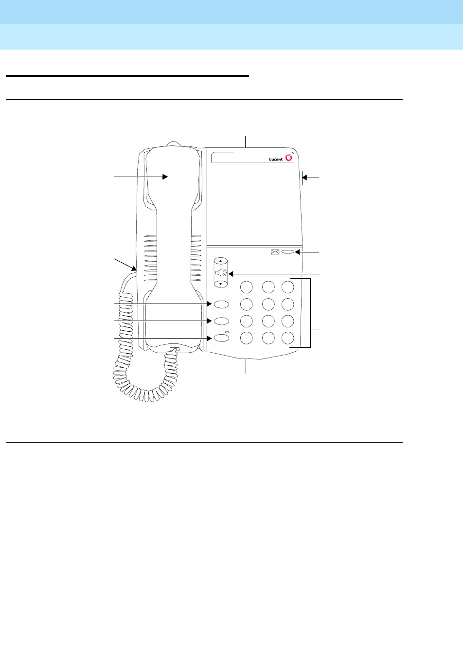
DEFINITYEnterpriseCommunicationsServerandSystem75andSystem85
Terminals and Adjuncts Reference
555-015-201 Issue 11
December 1999
The 6200 Series Telephones
15-2The 6210 Telephone
15
The 6210 Telephone
Figure 15-1. The 6210 Telephone
The 6210 telephone is a single-line analog model that requires one tip and ring
pair for operation. This telephone has a Ringer volume control on the side of the
telephone and a Handset volume control on the front of the set. It uses only
Touch-Tone dialing and it also supports the Positive Disconnect function. In
addition, this telephone has a Message light, a FLASH button which allows
access to system features, a REDIAL button which allows automatic redial, a
HOLD button with a single associated light, and a DATA jack on the rear of the
telephone.
6210
1
4
7
*
2
5
8
3
6
9
0#
ABC DEF
JKLGHI MN O
PQRS TUV W XYZ
Handset
Handset
Handset
LINE jack
Dial pad
Ringer
cord jack
volume
control
(on bottom
of telephone)
volume
control
Flash
Redial
Hold
Message
light
DATA jack
Flash button
Redial button
Hold button

DEFINITYEnterpriseCommunicationsServerandSystem75andSystem85
Terminals and Adjuncts Reference
555-015-201 Issue 11
December 1999
The 6200 Series Telephones
15-3The 6210 Telephone
15
Applications
The 6210 telephone can be used with the DEFINITY Communications System
Generic 1, Generic 2, and Generic 3, the DEFINITY ECS, System 75, and
System 85. The telephone has local phone features such as Hold and Redial, and
can also be used for the system features with the FLASH button.
Physical Description
Dimensions
NOTE:
The dimensions listed here for the 6210 telephone are approximate.
Width = 6.57 inches (16.69 cm)
Depth (front to back) = 8.8 inches (22.35 cm)
Height (maximum with handset in place) = 3.3 inches (8.38 cm)
Feature Buttons
Fixed Feature Buttons
The 6210 telephone has a FLASH button, which can be used for such features as
Conference with business communications systems.
This telephone also has a REDIAL button, which can be used for redialing the last
number dialed from the dial pad, either an extension or an outside number. The
number redialed can be up to 24 digits.
The 6210 also has a HOLD button, which can be used for putting a call on hold.
Message Light (only on the 6210 telephone)
The red Message light on the 6210 telephone flashes when a message is left for
the user. It goes off when the user retrieves the message. The Message light also
serves as a visual ringing indicator by flashing quickly while the telephone is
ringing.
Other Physical Features
Ringing
The 6210 telephone has electronic tone ringing. The ringer volume control
is a 3-position switch on the right side of the housing. The volume control is
labeled .

DEFINITYEnterpriseCommunicationsServerandSystem75andSystem85
Terminals and Adjuncts Reference
555-015-201 Issue 11
December 1999
The 6200 Series Telephones
15-4The 6210 Telephone
15
The user can also select one of two different ringing patterns. The two ringing
pattern settings are labeled (choose one or the other) and located on the
rear of the telephone.
Touch-Tone Dialing
The 6210 telephone has
only
Touch-Tone Dialing. No special setting is needed to
engage this feature.
Timed Disconnect
The 6210 supports the Timed Disconnect feature. No special setting is needed to
engage this feature.
Mounting Options
This telephone comes equipped with a non-adjustable desk stand which can be
turned upside-down and used for wall mounting the telephone.
Jacks
The 6210 telephone has a Line jack (labeled LINE) on the back of the telephone
for connecting a line cord, and a Handset cord jack (labeled ) for connecting
the handset.
This telephone also has a Data jack (labeled ) for connecting a device such as
a modem to the telephone.
Handset
The 6210 telephone is equipped with a K-type handset.
Dial pad
The 6210 telephone is equipped with a 12-button touch-tone dial pad. The letters
“Q” and “Z” have been added to the appropriate dial pad keys for directory access,
and the “5” button on the dial pad has raised bars for visually-impaired users.
Cords
Two cords are supplied with the 6210 telephone: a coiled 9-foot modular handset
cord and a 7-foot modular line cord.
Color Options
The 6210 telephone is available in black and in white.
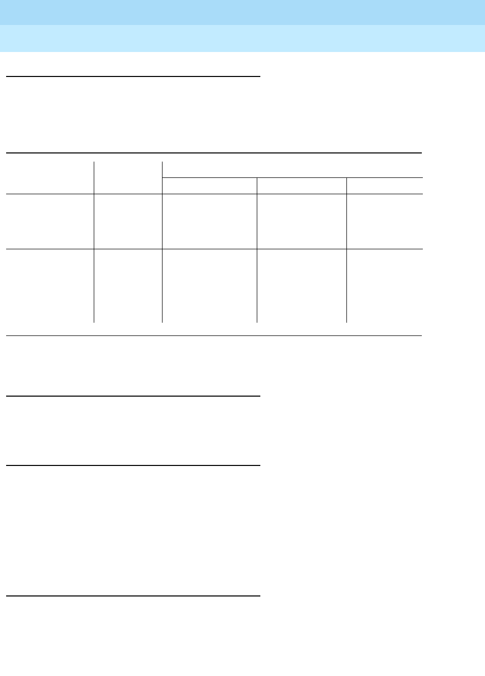
DEFINITYEnterpriseCommunicationsServerandSystem75andSystem85
Terminals and Adjuncts Reference
555-015-201 Issue 11
December 1999
The 6200 Series Telephones
15-5The 6210 Telephone
15
Distance Limitations
The maximum allowable distances of a 6210 telephone from the DEFINITY G1,
G2, and G3, DEFINITY ECS, System 75, or System 85 cabinet are shown in the
table below.
Power Requirements
The 6210 telephone receives power from the system and does not require any
external power supply.
Switch Administration
The 6210 telephone must be administered in the following ways:
■If the 6210 telephone is connected to a System 75, a DEFINITY G1 or G3,
or a DEFINITY ECS, it must be administered as a 2500 analog telephone
with Message Waiting
.
■If the 6210 telephone is connected to a System 85 or a DEFINITY G2, it
can be administered as an analog line.
Power Failure Operation
The 6210 telephone can be used as an emergency station during power failure
transfer conditions.
Table 15-1. Distance Limitations for the 6210 Telephone
System Port Board
Nominal Maximum Range in Feet (Meters)
22 AWG 24 AWG 26 AWG
DEFINITY G2
and
System 85
SN228
SN228B
SN229
12,000 (3,660) 8,000 (2,440) 5,000 (1,525)
DEFINITY G1
and G3,
DEFINITY ECS,
and System 75
TN746B
TN742
TN769
TN746
19,000 (5,795)
3,900 (1,189)
12,000 (3,660)
2,500 (762)
7,500 (2,287)
1,500 (457)

DEFINITYEnterpriseCommunicationsServerandSystem75andSystem85
Terminals and Adjuncts Reference
555-015-201 Issue 11
December 1999
The 6200 Series Telephones
15-6The 6210 Telephone
15
Ringer Equivalency Numbers
The Ringer Equivalency Number for the 6210 is: AC REN 0.7A, 1.6B
FCC Registration
The 6210 telephone is FCC registered. The Registration Number of the 6210 is:
AS5CHN-25251-MT-E.
Hearing Aid Compatible
This telephone is compatible with the inductively coupled hearing aids approved
by the FCC.
6210 Telephone PECs and Comcodes
The 6210 telephone and optional components can be ordered with the following
PECs and Comcodes:
■The 6210 (6210A01A) Telephone
PEC: White=3198-10W; Gray=3198-10G
Comcode: White=108099219; Gray=108099235
■Handset
Comcode: White=108216185; Gray=108216193
■Handset cord (9 feet)
Comcode: White=407632835; Gray=407632850
■Line cord (7 feet)
Comcode: 105642980
■Line cord (14 feet, silver)
PEC: 2725-07N (COL18)
Comcode: 103786802
■Line cord (25 feet, silver)
PEC: 2725-07S (COL18)
Comcode: 103786828
■Desk/Wall Mount base
Comcode: White=848020079; Gray=848020087
Adjuncts
The 6210 telephone does not have an Adjunct equipment jack and therefore will
not support any adjuncts.

DEFINITYEnterpriseCommunicationsServerandSystem75andSystem85
Terminals and Adjuncts Reference
555-015-201 Issue 11
December 1999
The 6200 Series Telephones
15-7The 6210 Telephone
15
Additional Documents
The following documents contain additional information relating to the 6210
telephone: (Use the 9-digit number listed after each document to order the book
from the BCS Publications Center for Lucent Technologies.)
DEFINITY
®
Enterprise Communications Server (ECS) Release 6 6210 and 6220
Telephones User’s Guide
, 555-230-712
The following instructions are shipped with the individual telephones:
■
6210 Telephone Quick Reference
, 555-230-709
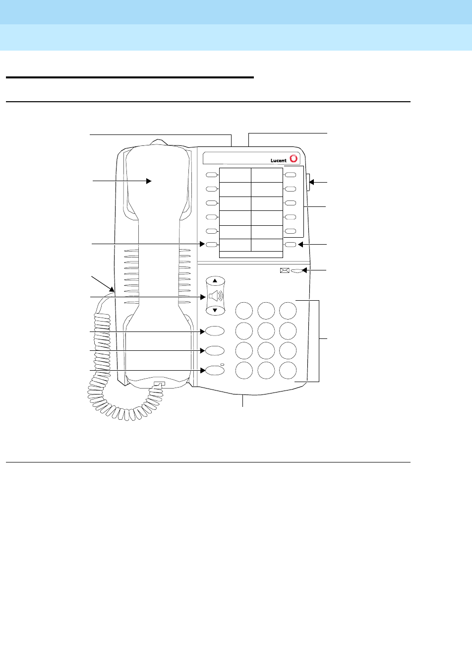
DEFINITYEnterpriseCommunicationsServerandSystem75andSystem85
Terminals and Adjuncts Reference
555-015-201 Issue 11
December 1999
The 6200 Series Telephones
15-8The 6218 and 6220 Telephones
15
The 6218 and 6220 Telephones
Figure 15-2. The 6218 Telephone
6220
1
4
7
*
2
5
8
3
6
9
0
#
ABC DEF
JKLGHI MNO
PQRS TUV WXYZ
Handset
Handset cord jack
DATA jack
Dial pad
Ringer volume
Handset volume
Message light
Flash button
Redial button
Hold button
LINE jack
Tel.#
Program Pause
Pause button
Personalized Ring
10 Programmable
Dialing buttons
Program button
Flash
Redial
Hold
control
(on bottom of telephone)
control
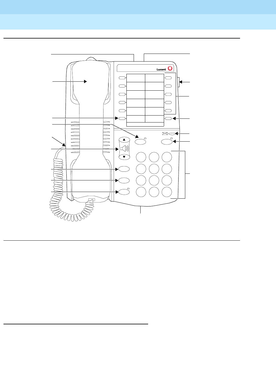
DEFINITYEnterpriseCommunicationsServerandSystem75andSystem85
Terminals and Adjuncts Reference
555-015-201 Issue 11
December 1999
The 6200 Series Telephones
15-9The 6218 and 6220 Telephones
15
Figure 15-3. The 6220 Telephone
Both the 6218 and the 6220 telephone are single-line analog sets that requires
one tip and ring pair for operation. These telephones have 10 programmable
dialing buttons, a REDIAL button which allows automatic redial, selected
personalized ringing pattern, a Message light, a HOLD button, and a Data jack.
The 6220 telephone (only) has a built-in speakerphone (accessed with the
SPEAKER button) with Mute capability (the MUTE button). Both telephones allow
access to system features with the FLASH button and appropriate dial codes.
Applications
The 6218 and 6220 telephones can be used with the DEFINITY Communications
System Generic 1, Generic 2, and Generic 3, the DEFINITY ECS, System 75, and
System 85. These telephones have local phone features, but can also be used
with the FLASH button for system features.
6220
1
4
7
*
2
5
8
3
6
9
0
#
ABC DEF
JKLGHI MNO
PQRS TUV WXYZ
Handset
Handset cord jack
DATA jack
Dial pad
Ringer volume
Handset volume
Message light
Flash button
Redial button
Hold button
LINE jack
Tel.#
Program Pause
Mute Spkr
Pause button
Personalized Ring
10 Programmable
Dialing buttons
Speakerphone
Mute button
Program button
Flash
Redial
Hold
control
button
(on bottom of telephone)
control

DEFINITYEnterpriseCommunicationsServerandSystem75andSystem85
Terminals and Adjuncts Reference
555-015-201 Issue 11
December 1999
The 6200 Series Telephones
15-10The 6218 and 6220 Telephones
15
Physical Description
Dimensions
NOTE:
The dimensions listed here for the 6218 and 6220 telephones are
approximate.
Width = 6.57 inches (16.69 cm)
Depth (front to back) = 8.8 inches (22.35 cm)
Height (maximum with handset in place) = 3.3 inches (8.38 cm)
Feature Buttons
Fixed Feature Buttons
Both the 6218 and the 6220 telephones have the following fixed feature buttons:
■FLASH button
For using features such as Conference with business communications
systems.
■REDIAL button
Can be used for redialing the last number dialed from the dial pad, either
an extension or an outside number. The number redialed can be up to
24 elements.
■HOLD button
Used for putting a call on hold.
■Message Light
The red Message light flashes when a message is left for the user. It goes
off when the user retrieves the message. The Message light also serves as
a visual ringing indicator by flashing quickly while the telephone is ringing.
■Programmable Dialing Buttons
These two telephones provide 10 programmable dialing buttons on which
the user can store frequently dialed telephone numbers or feature codes.
To use these preprogrammed features, the user merely lifts the handset or
turns on the speakerphone and then presses the appropriate
programmable dialing button.

DEFINITYEnterpriseCommunicationsServerandSystem75andSystem85
Terminals and Adjuncts Reference
555-015-201 Issue 11
December 1999
The 6200 Series Telephones
15-11The 6218 and 6220 Telephones
15
■PROGRAM and PAUSE buttons
The PROGRAM button is used for storing numbers on the programmable
dialing buttons on the upper half of the faceplate of the telephone. The
PAUSE button can be used to insert a one half second pause/delay into a
telephone number stored on a programmable dialing button.
In addition, the 6220 telephone has the following two features:
■SPEAKERPHONE button
For accessing the built-in speakerphone and microphone combination.
■MUTE button
Turns off the microphone associated with either the speakerphone or the
handset, whichever is active.
Other Physical Features
Ringing
The 6218 and 6220 telephones have electronic tone ringing. The ringer volume
control is a 3-position switch on the right side of the housing. The volume control
is labeled .
The user can also select one of two different ringing patterns. The two ringing
pattern settings are labeled (choose one or the other) and located on the
rear of the telephone.
Handset and Speakerphone volume control
The volume control (labeled ) is used for raising or lowering the volume of the
handset when the handset is being used, or for raising or lowering the volume of
the speakerphone when the speakerphone is active. To raise the volume level,
press the upper half of the button labeled ; to lower the volume, press the
lower half of the button labeled .
Mounting Options
The 6218 and 6220 telephones come equipped with a non-adjustable desk stand
which can be turned upside-down and used for wall mounting the telephone.
Jacks
The 6218 and 6220 telephones have a Line jack (labeled LINE) on the back of the
telephone for connecting a line cord, and a Handset cord jack (labeled ) on
the side of the telephone for connecting the handset. The telephone also has a
Data jack (labeled ) on the rear of the set for connecting a device such as a
modem to the telephone.
Handset
The 6218 and 6220 telephones are equipped with a K-type handset.

DEFINITYEnterpriseCommunicationsServerandSystem75andSystem85
Terminals and Adjuncts Reference
555-015-201 Issue 11
December 1999
The 6200 Series Telephones
15-12The 6218 and 6220 Telephones
15
Dial pad
The 6218 and 6220 telephones are equipped with a 12-button touch-tone dial
pad. The letters “Q” and “Z” have been added to the appropriate dial pad keys for
directory access, and the “5” button on the dial pad has raised bars for
visually-impaired users.
Cords
Two cords are supplied with the 6218 and 6220 telephone: a coiled 9-foot modular
handset cord and a 7-foot modular line cord.
Color Options
The 6218 and 6220 telephones are available in black and in white.
Distance Limitations
The maximum allowable distances of a 6218 and 6220 telephone from the
DEFINITY G1, G2, and G3, DEFINITY ECS, System 75, or System 85 cabinet are
shown in the table below.
Power Requirements
The 6218 and 6220 telephones receive power from the system and do not require
any external power supply.
Table 15-2. Distance Limitations for the 6218 and 6220 Telephones
System Port Board
Nominal Maximum Range in Feet (Meters)
22 AWG 24 AWG 26 AWG
DEFINITY G2
and
System 85
SN228
SN228B
SN229
12,000 (3,660) 8,000 (2,440) 5,000 (1,525)
DEFINITY G1
and G3,
DEFINITY ECS,
and System 75
TN746B
TN742
TN769
TN746
19,000 (5,795)
3,900 (1,189)
12,000 (3,660)
2,500 (762)
7,500 (2,287)
1,500 (457)
DEFINITYEnterpriseCommunicationsServerandSystem75andSystem85
Terminals and Adjuncts Reference
555-015-201 Issue 11
December 1999
The 6200 Series Telephones
15-13The 6218 and 6220 Telephones
15
Switch Administration
The 6218 and 6220 telephones must be administered in the following ways:
■If the telephone is connected to a System 75, DEFINITY G1 or G3, or a
DEFINITY ECS, it must be administered as a 2500 analog telephone with
Message Waiting.
■If the telephone is connected to a System 85 or DEFINITY G2, it can be
administered as an analog line.
NOTE:
The programmable dialing buttons are programmed individually on the
telephone; they are
not
administrable from the switch.
Power Failure Operation
The6218 and 6220 telephones can be used as an emergency station during
power failure transfer conditions.
Ringer Equivalency Numbers
The Ringer Equivalency Number for the 6218 and 6220 telephones is: 0.5A, 1.5B.
FCC Registration
The 6218 and 6220 telephone are FCC registered (AS5CHN-25383-MT-T).
Hearing Aid Compatible
These telephones are compatible with the inductively coupled hearing aids
approved by the FCC.
6218 and 6220 Telephones PECs and Comcodes
The 6218 and 6220 telephones and optional components can be ordered with the
following PECs and Comcodes:
■The 6218 (6218A01A) Telephone
Deep Gray, with English standard-labeled buttons
PEC: 3198-18G; Comcode: 108459868
White, with English standard-labeled buttons)
PEC: 3198-18W; CC#108459850
■The 6220 (6220A01A) Telephone
PEC: White=3198-20W; Gray=3198-20G
Comcode: White=108099250; Gray=108099268

DEFINITYEnterpriseCommunicationsServerandSystem75andSystem85
Terminals and Adjuncts Reference
555-015-201 Issue 11
December 1999
The 6200 Series Telephones
15-14The 6218 and 6220 Telephones
15
■Handset
Comcode: White=108216185; Gray=108216193
■Handset cord (9 feet)
Comcode: White=407632835; Gray=407632850
■Line cord (7 feet)
Comcode: 105642980
■Line cord (14 feet, silver)
PEC: 2725-07N (COL18)
Comcode: 103786802
■Line cord (25 feet, silver)
PEC: 2725-07S (COL18)
Comcode: 103786828
■Programmable Dialing Button designation cards
Single sheet
Comcode: 848033932
The details of multiple-card packages have not yet been designated.
■Designation card covers
Single card cover
Comcode: 848033940
The details of multiple-card cover packages have not yet been designated.
■Desk/Wall Mount base
Comcode: White=848020079; Gray=848020087
Adjuncts
The 6218 and 6220 telephones do not have an Adjunct equipment jack and
therefore will not support any adjuncts.
Additional Documents
The following documents contain additional information relating to the 6218 and
6220 telephones: (Use the 9-digit number listed after each document to order the
book from the BCS Publications Center for Lucent Technologies.)
■
DEFINITY
®
Enterprise Communications Server (ECS) Release 6 6210 and
6220 Telephones User’s Guide
, 555-230-712
The following instructions are shipped with every 6218 and 6220 telephone:
■
6218 and 6220 Telephones Quick Reference
, 555-230-713

The 8100 Series Telephones
16-1
16
DEFINITYEnterpriseCommunicationsServerandSystem75andSystem85
Terminals and Adjuncts Reference
555-015-201 Issue 11
December 1999
16
The 8100 Series Telephones
The following 8100 Series telephones are described in this section:
■8101 and the 8101M telephones
■8102 and the 8102M telephones
■8110 and the 8110M telephones
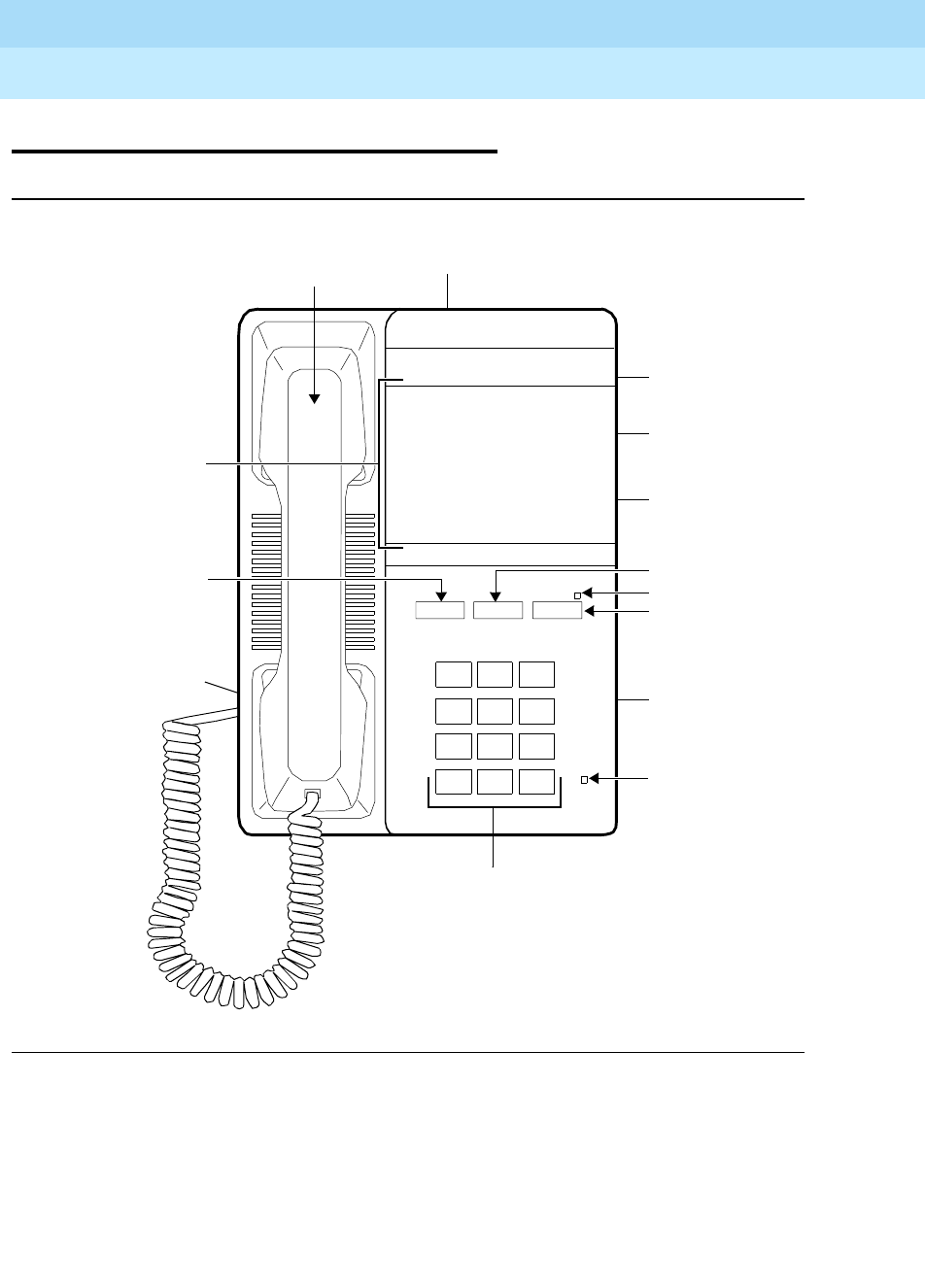
DEFINITYEnterpriseCommunicationsServerandSystem75andSystem85
Terminals and Adjuncts Reference
555-015-201 Issue 11
December 1999
The 8100 Series Telephones
16-2The 8101 and 8101M Telephones
16
The 8101 and 8101M Telephones
Figure 16-1. The 8101 Telephone
THIS NUMBER
Message
123
456
789
ABC DEF
MNOJKLGHI
PQRS TUV WXYZ
*
O#
OPER
8101
Dial Pad
Handset Jack
Flash Button
Labeling
Redial Button
Hold Light
Hold Button
Message Light
Flash Redial Hold
Data Jack
Handset
Designation
Card
(on rear of housing)
Reversible
Stand (on
bottom of
telephone)
Mode Selector
(on right side
of telephone)
Positive
Disconnect
(on right side
of telephone)
Ringer Volume
Control (on right
side of telephone)
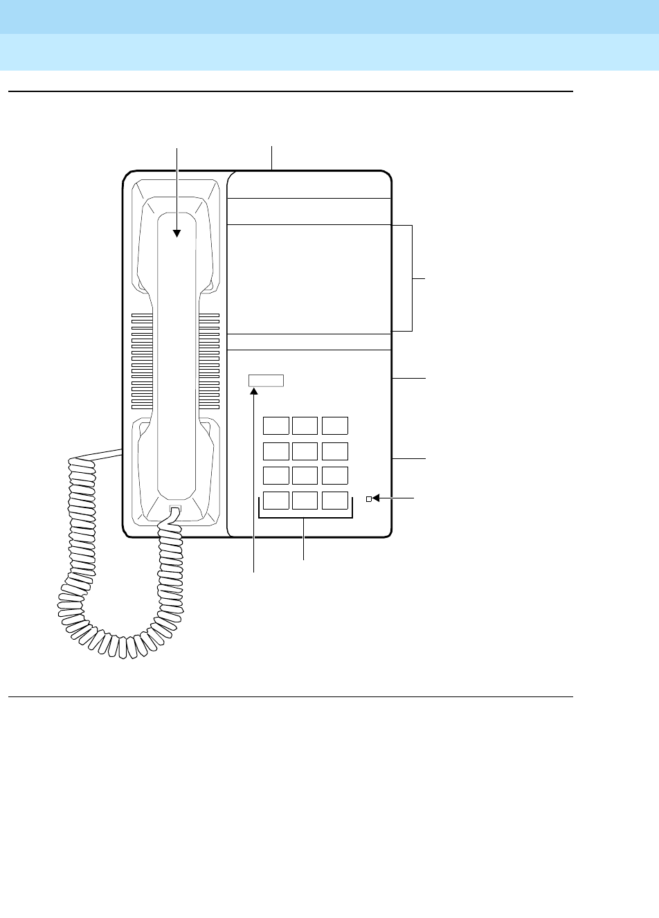
DEFINITYEnterpriseCommunicationsServerandSystem75andSystem85
Terminals and Adjuncts Reference
555-015-201 Issue 11
December 1999
The 8100 Series Telephones
16-3The 8101 and 8101M Telephones
16
Figure 16-2. The 8101M Telephone
The 8101 and 8101M telephones are single-line analog models that require one
tip and ring pair for operation. These telephones contain a Message light, a
designation card on which the user can write frequently-dialed numbers and
extensions, selectable personalized ringing pattern, and a Data jack. The 8101
and 8101M telephones allow access to system features with the FLASH button
and appropriate dial codes. The 8101 telephone provides the added features of
automatic redial (with a REDIAL button) and a HOLD button with a single
associated light.
THIS NUMBER
Message
123
456
789
ABC DEF
MNOJKLGHI
PQRS TUV WXYZ
*
O#
OPER
8101
Dial Pad
Flash
Message Light
Flash
Data Jack
Handset
Designation
Card
(on rear of housing)
Ringer
Volume
Control
(on right side
of telephone)
Reversible Stand
(on bottom of
telephone)
Button

DEFINITYEnterpriseCommunicationsServerandSystem75andSystem85
Terminals and Adjuncts Reference
555-015-201 Issue 11
December 1999
The 8100 Series Telephones
16-4The 8101 and 8101M Telephones
16
Applications
The 8101 and 8101M telephones can be used with the DEFINITY
Communications System Generic 1, Generic 2, and Generic 3, the DEFINITY
ECS, System 75, and System 85. These telephones have local phone features,
but can also be used for the system features with the FLASH button.
Physical Description
Dimensions
NOTE:
The dimensions listed here for the 8101 and 8101M telephones are
approximate.
Width = 6-3/4 inches
Depth (front to back) = 9-1/2 inches
Height (maximum with handset in place) = 3-1/2 inches
Thickness of housing = At the top of the telephone, the thickness measures
1-5/8 inches; at the bottom of the telephone, the thickness measures 1 inch.
Feature Buttons
Fixed Feature Buttons
Both the 8101 and 8101M telephones have a FLASH button, which can be used
for such features as Conference with business communications systems.
The 8101 also has a REDIAL button, which can be used for redialing the last
number dialed from the dial pad, either an extension or an outside number. The
number redialed can be up to 20 digits.
The 8101 also has a HOLD button, which can be used for putting a call on hold. If
users want to put a call on hold and place another call, they must use the system
Hold feature by using the FLASH button.
Message Light
The red Message light flashes when a message is left for the user. It goes off
when the user retrieves the message. The Message light also serves as a visual
ringing indicator by flashing quickly while the telephone is ringing.
Designation Card
On the front of the 8101 and 8101M, there is a designation card on which the user
can write frequently-dialed telephone numbers and extensions.

DEFINITYEnterpriseCommunicationsServerandSystem75andSystem85
Terminals and Adjuncts Reference
555-015-201 Issue 11
December 1999
The 8100 Series Telephones
16-5The 8101 and 8101M Telephones
16
Other Physical Features
Ringing
The 8101 and 8101M telephones have electronic tone ringing. The ringer volume
control is a 3-position switch on the right side of the housing.
Positive Disconnect
The 8101 telephone has a switch with which the user can select positive
disconnect or turn it off. In the ON position, this switch hangs up the phone for
approximately two seconds, even if the switchhook depression is for a shorter
duration. This action prevents inadvertent switchhook flashes. To initiate a
switchhook flash in this mode, the FLASH button must be pressed. In the OFF
position, switchhook functioning is normal.
Mode Selector
The 8101 telephone has a 2-position switch which allows the user to select either
rotary pulse or touch tone dialing.
Mounting Options
The 8101 and 8101M telephones come equipped with a non-adjustable desk
stand which can be turned upside-down and used for wall mounting the
telephone.
Jacks
The 8101 and 8101M telephones have a Line jack on the back of the telephone
for connecting a line cord, and a Handset cord jack for connecting the handset.
These telephones also have a Data jack for connecting a device such as a
modem to the telephone.
Handset
The 8101 and 8101M telephones are equipped with a K-type handset.
Dial pad
The 8101 and 8101M telephones are equipped with a 12-button touch-tone dial
pad. The letters “Q” and “Z” have been added to the appropriate dial pad keys for
directory access, and the “5” button on your dial pad has raised bars for
visually-impaired users.
Cords
Two cords are supplied with the 8101 and 8101M telephones: a coiled 9-foot
modular handset cord and a 7-foot modular line cord.
Color Options
The 8101 and 8101M telephones are available in black and in white.
DEFINITYEnterpriseCommunicationsServerandSystem75andSystem85
Terminals and Adjuncts Reference
555-015-201 Issue 11
December 1999
The 8100 Series Telephones
16-6The 8101 and 8101M Telephones
16
Distance Limitations
The maximum allowable distances of an 8101 or 8101M telephone from the
DEFINITY G1, G2, and G3, DEFINITY ECS, System 75, or System 85 cabinet are
shown in the table below.
Power Requirements
The 8101 and 8101M telephones receive power from the system and do not
require any external power supply.
Switch Administration
The 8101 and 8101M telephones must be administered in the following ways:
■If the 8101 or 8101M telephone is connected to a System 75, a
DEFINITY G1 or G3, or a DEFINITY ECS, it must be administered as a
2500 analog telephone with Message Waiting.
■If the 8101 or 8101M telephone is connected to a System 85 or a
DEFINITY G2, it can be administered as an analog line.
Power Failure Operation
The 8101 and 8101M telephone can be used as an emergency station during
power failure transfer conditions.
Table 16-1. Distance Limitations for the 8101 and 8101M Telephones
System Port Board
Nominal Maximum Range in Feet
(Meters)
24 AWG 26 AWG
System 85 SN229
SN228B
6,500 (1,981)
6,500 (1,981)
4,100 (1,246)
4,100 (1,246)
DEFINITY G2 SN229
SN228B
TN742
TN746
6,500 (1,981)
6,500 (1,981)
15,200 (4,633)
3,000 (915)
4,100 (1,246)
4,100 (1,246)
10,000 (3,050)
2,000 (610)
DEFINITY G1 and
G3, DEFINITY
ECS, and System
75
TN742
TN769
TN746
15,200 (4,633)
15,200 (4,633)
3,000 (915)
10,000 (3,050)
10,000 (3,050)
2,000 (610)

DEFINITYEnterpriseCommunicationsServerandSystem75andSystem85
Terminals and Adjuncts Reference
555-015-201 Issue 11
December 1999
The 8100 Series Telephones
16-7The 8101 and 8101M Telephones
16
Ringer Equivalency Numbers
The Ringer Equivalency Number for the 8101 and 8101M telephones is:
REN 0.4A, 0.8B.
FCC Registration
The 8101 and 8101M telephones are FCC registered (AS5CHN-20714-MT-E).
Hearing Aid Compatible
These two telephones are compatible with the inductively coupled hearing aids
prescribed by the FCC.
8101 and 8101M Telephones PECs and Comcodes
The 8101 and 8101M telephones and optional components can be ordered with
the following PECs and Comcodes:
■Basic 8101Telephone
PEC: 3192-101 (Black=COL09; White=COL10)
Comcode: Black=106272289; White=106272297
■8101M Telephone
PEC (through 1996): 3192-102 (Black=COL09; White=COL10)
Comcode (through 1996): Black=107358889; White=107358897
Comcode (starting in 1997): Black=107730491; White=107305509
■Handset
Comcode: Black=107136800; White=106063408
■Handset cord (9 feet)
Comcode: Black=107154262; White: 107154270
■Line cord (7 feet)
Comcode: 107123069
■Line cord (14 feet, silver)
PEC: 2725-07N (COL18)
Comcode: 103786802
■Line cord (25 feet, silver)
PEC: 2725-07S (COL18)
Comcode: 103786828

DEFINITYEnterpriseCommunicationsServerandSystem75andSystem85
Terminals and Adjuncts Reference
555-015-201 Issue 11
December 1999
The 8100 Series Telephones
16-8The 8101 and 8101M Telephones
16
■Designation strips
PEC: 31941 (Package of 25)
Comcode: 847367539
PEC: 31942 (Package of 100)
Comcode: 847367547
■Designation card covers
Comcode: 847173937
Adjuncts
The 8101 and 8101M telephones do not have an Adjunct equipment jack and
therefore will not support any adjuncts.
Additional Documents
The following documents contain additional information relating to the 8101 and
8101M telephone: (Use the 9-digit number listed after each document to order the
book from the BCS Publications Center for Lucent Technologies.)
■
DEFINITY Communications System Generic 1, Generic 2, and Generic 3,
System 75 and System 85 8101, 8102, 8102M, 8110, 8110M Telephones
User’s Guide
, 555-230-774
The following instructions are shipped with every 8101 and 8101M telephone:
■
8101, 8102 and 8110 Telephones User’s Manual
, 555-015-131
■
8101, 8101M, 8102M and 8110M Telephones Quick Reference Guide
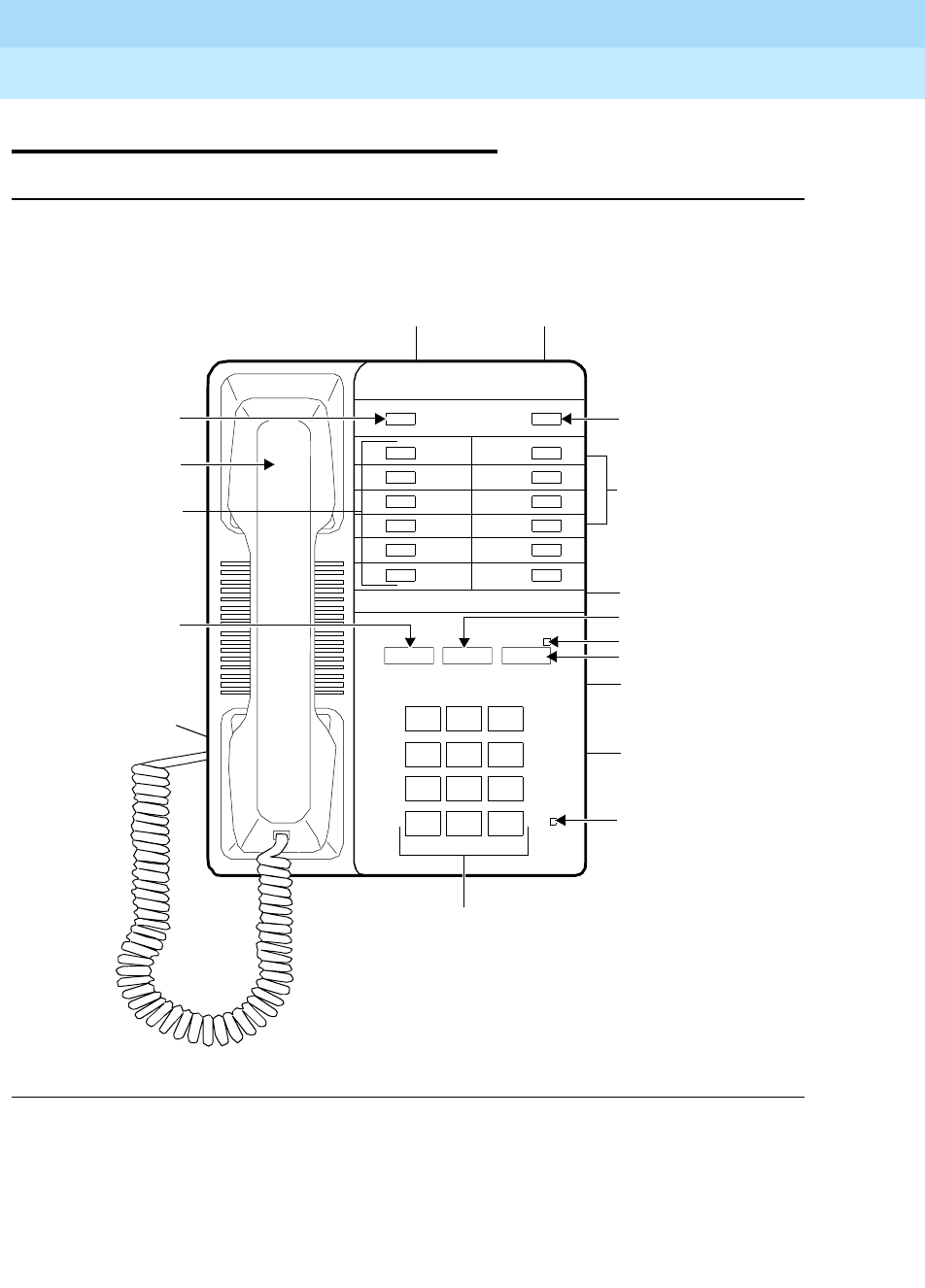
DEFINITYEnterpriseCommunicationsServerandSystem75andSystem85
Terminals and Adjuncts Reference
555-015-201 Issue 11
December 1999
The 8100 Series Telephones
16-9The 8102 and 8102M Telephones
16
The 8102 and 8102M Telephones
Figure 16-3. The 8102 and 8102M Telephone
The basic 8102 telephone (which includes the 8102A01A and 8102A01B) and the
modified 8102M (8102A01C) telephone are single-line analog sets that require
one tip and ring pair for operation. These telephones are exactly the same in
appearance: each contains 12 programmable dialing buttons, automatic redial
(with the REDIAL button), selected personalized ringing pattern, a Message light,
THIS NUMBER
Message
123
456
789
ABC DEF
MNOJKLGHI
PQRS TUV WXYZ
*
O#
OPER
8102
Dial Pad
Handset Jack
Flash Button
Handset
Adjunct (equipment)
12 Programmable
Pause Button
Redial Button
Hold Light
Hold Button
Message Light
Flash Redial Hold
PROGRAM PAUSE
Data Jack
Dialing Buttons
Program Button
(on rear of housing) Jack (on rear of housing)
Ringer Volume
Control (on side of
Ringer Volume
Control (on side
Ringer Tone
Selectors (on side
of voice terminal)
voice terminal)
of voice terminal)
Adjunct Power Jack
(on back of voice
terminal)

DEFINITYEnterpriseCommunicationsServerandSystem75andSystem85
Terminals and Adjuncts Reference
555-015-201 Issue 11
December 1999
The 8100 Series Telephones
16-10The 8102 and 8102M Telephones
16
a HOLD button, a Data jack, and an Adjunct jack. The 8102 and 8102M
telephones also allow access to system features with the FLASH button and
appropriate dial codes.
NOTE:
In late 1995, the basic 8102 telephone was no longer manufactured. Only
the 8102M is available.
Applications
The 8102 and 8102M telephones can be used with the DEFINITY
Communications System Generic 1, Generic 2, and Generic 3, the DEFINITY
ECS, System 75, and System 85. These telephones have local phone features,
but can also be used with the FLASH button for system features.
The 8102 and 8102M telephones can be converted to a hotel/motel telephone for
the lodging industry. The converted telephone has 10 pre-programmed buttons
which enable users easy communication with assigned numbers within the
hotel/motel, such as the front desk or housekeeping service, for instance.
Physical Description
Dimensions
NOTE:
The dimensions listed here for the 8102 and 8102M telephones are
approximate.
Width = 6-3/4 inches
Depth (front to back) = 9-1/2 inches
Height (maximum with handset in place) = 3-1/2 inches
Thickness of housing = At the top of the telephone, the thickness measures
1-5/8 inches; at the bottom of the telephone, the thickness measures 1 inch.
Feature Buttons
Fixed Feature Buttons
The 8102 and 8102M telephones have the following fixed feature buttons:
■FLASH button
For using features such as Conference with business communications
systems.

DEFINITYEnterpriseCommunicationsServerandSystem75andSystem85
Terminals and Adjuncts Reference
555-015-201 Issue 11
December 1999
The 8100 Series Telephones
16-11The 8102 and 8102M Telephones
16
■REDIAL button
Can be used for redialing the last number dialed from the dial pad, either
an extension or an outside number. The number redialed can be up to
20 digits.
With the (Redial) Auto-Pause feature, the telephone can be programmed to
insert pauses after a dial access code (such as 9) in a redialed number. If
the user usually waits a short period to obtain a second dial tone after
dialing an access code, this waiting time can be set by programming the
automatic pause between the system access code and the telephone
number. The (Redial) Auto-Pause feature will help eliminate misdialing.
■HOLD button
Used for putting a call on hold. If users want to put a call on hold and place
another call, they must use the system Hold feature by using the FLASH
button.
■Message Light
The red Message light flashes when a message is left for the user. It goes
off when the user retrieves the message. The Message light also serves as
a visual ringing indicator by flashing quickly while the telephone is ringing.
■Programmable Dialing Buttons
The 8102 and 8102M telephones provide 12 programmable dialing buttons
on which the user can store frequently dialed telephone numbers or feature
codes. To use these preprogrammed features, the user merely lifts the
handset and then presses the appropriate programmable dialing button.
■PROGRAM and PAUSE buttons
Both of these buttons are used for storing numbers on the preprogrammed
dialing buttons on the upper half of the faceplate of the telephone. The
PAUSE button can be used to insert a one half second pause/delay into a
telephone number stored on a programmable dialing button or into a dialing
access code in the Auto-Pause feature of Redial.
Other Physical Features
Ringing
The 8102 and 8102M telephones have electronic tone ringing. The ringer volume
control is a 3-position switch on the right side of the housing.
The user can also use a Tone Selector (labeled “LO HI”) for selecting one of two
tone ringer frequencies or a second Tone Selector (labeled “SLOW FAST”) for
selecting one of two tone ringer modulation rates. Both Tone Selector switches are
on the right side of the telephone.

DEFINITYEnterpriseCommunicationsServerandSystem75andSystem85
Terminals and Adjuncts Reference
555-015-201 Issue 11
December 1999
The 8100 Series Telephones
16-12The 8102 and 8102M Telephones
16
Mounting Options
The 8102 and 8102M telephones come equipped with a non-adjustable desk
stand which can be turned upside-down and used for wall mounting the
telephone.
Jacks
The 8102 and 8102M telephones have a line jack on the back of the telephone for
connecting a line cord, and a Handset cord jack for connecting the handset.
These telephones also have a Data jack for connecting a device such as a
modem to the telephone.
The 8102 and 8102M telephones have an Adjunct (equipment) jack which allows
the connection of a speakerphone to the telephone and an adjunct power jack for
connecting an auxiliary power source for using the adjunct equipment.
Handset
The 8102 and 8102M telephones are equipped with a K-type handset.
Dial pad
The 8102 and 8102M telephones have a 12-button touch-tone dial pad. The
letters “Q” and “Z” have been added to the appropriate dial pad keys for directory
access, and the “5” button on your dial pad has raised bars for visually-impaired
users.
Cords
Two cords are supplied with the 8102 and 8102M telephones: a coiled 9-foot
modular handset cord and a 7-foot modular line cord.
Color Options
The 8102 and 8102M telephones are available in black and in white.
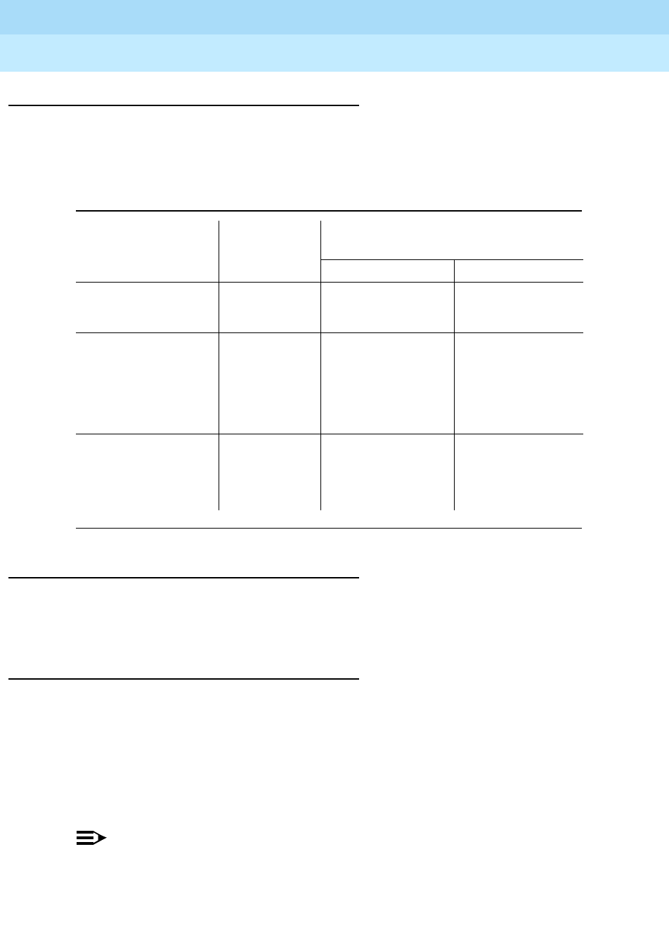
DEFINITYEnterpriseCommunicationsServerandSystem75andSystem85
Terminals and Adjuncts Reference
555-015-201 Issue 11
December 1999
The 8100 Series Telephones
16-13The 8102 and 8102M Telephones
16
Distance Limitations
The maximum allowable distances of an 8102 or 8102M telephone from the
DEFINITY G1, G2, and G3, DEFINITY ECS, System 75, or System 85 cabinet are
shown in the table below.
Power Requirements
The 8102 and 8102M telephones must have auxiliary power for adjunct
equipment when such equipment is connected.
Switch Administration
The 8102 and 8102M telephones must be administered in the following ways:
■If the 8102 or 8102M telephone is connected to a System 75, DEFINITY
G1 or G3, or a DEFINITY ECS, it must be administered as a 2500 analog
telephone with Message Waiting
■If the 8102 or 8102M telephone is connected to a System 85 or
DEFINITY G2, it can be administered as an analog line.
NOTE:
The programmable dialing buttons are programmed individually on the
telephone; they are
not
administrable from the switch.
Table 16-2. Distance Limitations for the 8102 and 8102M Telephones
System Port Board
Nominal Maximum Range in Feet
(Meters)
24 AWG 26 AWG
System 85 SN229
SN228B 6,500 (1,981) 4,100 (1,246)
DEFINITY G2 SN229
SN228B
TN742
TN746
6,500 (1,981)
6,500 (1,981)
15,200 (4,633)
3,000 (915)
4,100 (1,246)
4,100 (1,246)
10,000 (3,050)
2,000 (610))
DEFINITY G1
and G3,
DEFINITY ECS,
and System 75
TN742
TN769
TN746
15,200 (4,633)
15,200 (4,633)
3,000 (915)
10,000 (3,050)
10,000 (3,050)
2,000 (610)

DEFINITYEnterpriseCommunicationsServerandSystem75andSystem85
Terminals and Adjuncts Reference
555-015-201 Issue 11
December 1999
The 8100 Series Telephones
16-14The 8102 and 8102M Telephones
16
Administration of Hidden Features
For procedures on administering the hidden features on the 8102M
(to be done
ONLY by the system administrator
)suchas:
■Reprogramming the Hold Feature
■Administering the Timed Disconnect Feature
■Locking the Programmable Dialing Buttons
Refer to the
8101, 8101M, 8102M and 8110M Telephones Quick Reference Guide
which comes in the box with the 8102M.
Power Failure Operation
The 8102 or 8102M telephone can be used as an emergency station during power
failure transfer conditions.
Ringer Equivalency Numbers
The Ringer Equivalency Number for the 8102 telephone is: 0.5A and 1.6B. For the
8102M the Ringer Equivalency Number is: 1.5B and 0.8A.
FCC Registration
The 8102 and 8102M telephones are FCC registered (A5SUSA-65132-MT-E).
Hearing Aid Compatible
These telephones are compatible with the inductively coupled hearing aids
prescribed by the FCC.
8102 and 8102M Telephones PECs and Comcodes
The 8102 and 8102M telephones and optional components can be ordered with
the following PECs and Comcodes:
■Basic 8102 (8102A01A and 8102A01B) Telephone
PEC: 3192-001 (Black=COL09; White=COL10)
Comcode: Black=106272305; White=106272313
■Modified 8102M (8102A01C) Telephone
PEC: 3192-001 (Black=COL09; White=COL10)
Comcode: Black=107538357; White=107538365
■Handset
Comcode: Black=106050065; White=106053408

DEFINITYEnterpriseCommunicationsServerandSystem75andSystem85
Terminals and Adjuncts Reference
555-015-201 Issue 11
December 1999
The 8100 Series Telephones
16-15The 8102 and 8102M Telephones
16
■Handset cord (9 feet)
Comcode: Black=105635429; White=105701809
■Line cord (7 feet)
Comcode: 103732541
■Line cord (14 feet, silver)
PEC: 2725-07N (COL18)
Comcode: 103786802
■Line cord (25 feet, silver)
PEC: 2725-07S (COL18)
Comcode: 103786828
■Button designation card
PEC: 31932 (Package of 25)
PEC: 31938 (Tractor Feed)
Single Sheet
Comcode: 846562700
25 Sheets
Comcode: 846562718
Tractor Feed
Comcode: 846562726
■Designation card covers
PEC: 31937 (package of 25)
Comcode: 106523236
■Repertory Dial buttons (Programmable dialing buttons)
(These buttons can be used to replace lost buttons or to
replace the two buttons removed for hotel/motel conversion.)
(Package of 80)
PEC: 31936
Comcode: 106503238
■Security designation card and cover
(These cards and covers are for concealing the PROGRAM and
PAUSE buttons and the two topmost programmable dialing buttons
so that unauthorized changes cannot be made to the programmable
dialing assignments.)
(Package of 25 cards and clear plastic designation card covers)
PEC: 31931
Comcode: 106248370
■Stands
(These stands can be used to replace damaged or broken stands.)
(Package of 5)
PEC: 31933
Comcode: 106503204

DEFINITYEnterpriseCommunicationsServerandSystem75andSystem85
Terminals and Adjuncts Reference
555-015-201 Issue 11
December 1999
The 8100 Series Telephones
16-16The 8102 and 8102M Telephones
16
Adjuncts
The 8102 and 8102M telephones can be equipped with one of the following
adjuncts:
■S101A Speakerphone (not orderable)
■S201A Speakerphone
Additional Documents
The following documents contain additional information relating to the 8102 and
8102M telephones: (Use the 9-digit number listed after each document to order
the book from the BCS Publications Center for Lucent Technologies.)
■
DEFINITY Communications System Generic 1, Generic 2, and Generic 3,
System 75 and System 85 8101, 8102, 8102M, 8110, 8110M Telephones
User’s Guide
, 555-230-774
The following instructions are shipped with every 8102 telephone:
■
8101, 8102 and 8110 Telephones User’s Manual
, 555-015-131
The following instructions are shipped with every 8102M telephone:
■
8101, 8101M, 8102M and 8110M Telephones Quick Reference Guide
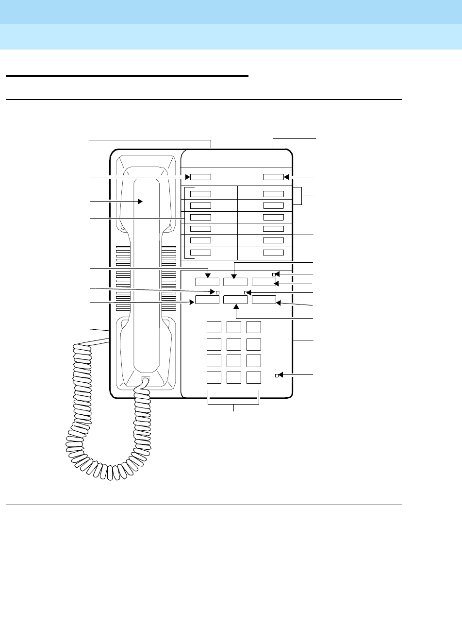
DEFINITYEnterpriseCommunicationsServerandSystem75andSystem85
Terminals and Adjuncts Reference
555-015-201 Issue 11
December 1999
The 8100 Series Telephones
16-17The 8110 and 8110M Telephones
16
The 8110 and 8110M Telephones
Figure 16-4. The 8110 and 8110M Telephones (The 8110M is shown here)
The basic 8110 (which includes the 8110A01A, 8110A01B, and 8110A01C) and
the modified 8110M (8110A01D) telephones are single-line analog sets that
require one tip and ring pair for operation. These telephones are exactly the same
in appearance: each contains 12 programmable dialing buttons with a PROGRAM
and PAUSE button for programming, automatic redial, selected personalized
ringing pattern, a flashing red Message light, and a HOLD button. They also have
a built-in speakerphone with Mute capability and the Automatic Answer (and
disconnect) feature. The 8110 and 8110M telephones also allow access to system
features via the FLASH button and appropriate dial codes.
Auxiliary Power Jack
Message
123
456
789
ABC DEF
MNOJKLGHI
PQRS TUV WXYZ
*
O#
OPER
Spkr Mute Auto
8110M
Dial Pad
Pause Button
Auto Answer Button
Redial Button
Hold Light
Hold Button
Message Light
Flash Redial Hold
PROGRAM PAUSE
Mute Button
Mute Light
THIS NUMBER
(on rear of housing)
Ringer Tone
Selectors (on
side of voice
terminal)
Ringer Volume
Control (on side
of voice terminal)
Speaker Volume
Control (on side
of voice terminal)
12 Programmable
Dialing Buttons
Handset Jack
Flash Button
Handset
Data Jack
Program Button
Speaker Button
(on rear of housing)
Speaker Light
DEFINITYEnterpriseCommunicationsServerandSystem75andSystem85
Terminals and Adjuncts Reference
555-015-201 Issue 11
December 1999
The 8100 Series Telephones
16-18The 8110 and 8110M Telephones
16
NOTE:
In late 1995, the basic 8110 was no longer manufactured. Only the 8110M is
available.
Applications
The 8110 and 8110M telephones can be used with the DEFINITY
Communications System Generic 1, Generic 2, and Generic 3, the DEFINITY
ECS, System 75, and System 85. These telephones have local phone features,
but can also be used for system features via the Flash button.
With the D-182363 Kit of Parts, the 8110 and 8110M telephones can be converted
to a hotel/motel telephone for the lodging industry. The converted telephone has
10 preprogrammed buttons (with the PROGRAM and PAUSE buttons and two
uppermost programmable dialing buttons concealed). The programmable dialing
buttons enable users easy communication with assigned numbers within the
hotel/motel, such as the front desk or housekeeping service. These telephones
can also be used in any unsecured location where hiding the Program and Pause
buttons is desirable.
Physical Description
Dimensions
NOTE:
The dimensions listed here for the 8110 and 8110M telephones are
approximate.
Width = 6-3/4 inches
Depth (front to back) = 9-1/2 inches
Height (maximum with handset in place) = 3-1/2 inches
Thickness of housing = At the top of the telephone, the thickness measures
1-5/8 inches; at the bottom of the telephone, the thickness measures 1 inch.
Features
Fixed Feature Buttons
The 8110 and 8110M telephones have the following fixed feature buttons:
■FLASH button
For using features such as Transfer or Conference with business
communications systems.

DEFINITYEnterpriseCommunicationsServerandSystem75andSystem85
Terminals and Adjuncts Reference
555-015-201 Issue 11
December 1999
The 8100 Series Telephones
16-19The 8110 and 8110M Telephones
16
■REDIAL button
Can be used for redialing the last number dialed from the dial pad, either
an extension or an outside number. The number redialed can be up to
20 digits.
With the (Redial) Auto-Pause feature, the telephones can be programmed
to insert pauses after a dial access code (such as 9) in a redialed number.
If the user usually waits a short period to obtain a second dial tone after
dialing an access code, this waiting time can be set by programming the
automatic pause between the system access code and the telephone
number. The (Redial) Auto-Pause feature will help eliminate misdialing.
■HOLD button
Used for putting a call on hold. If users want to put a call on hold and place
another call, they must access the system Hold feature by using the Flash
button.
■Speakerphone button (labeled SPKR)
Used for 2-way conversation with another party without lifting the handset.
Speaker volume is controlled by using the Speaker volume control switch
on the right side of the telephone.
■MUTE button
Used for turning off the microphone of the built-in speakerphone or the
handset.
■Auto Answer button (labeled AUTO)
Used for enabling calls to be automatically answered a call without lifting
the handset. For those who require speakerphone functionality without use
of the Auto-Answer feature, the Auto-Answer button can be removed and
replaced with a flat cap cover shipped with each 8110 and 8110M
telephone.
Message Light
The red Message light flashes when a message is left for the user. It goes off
when the user retrieves the message. The Message light also serves as a visual
ringing indicator by flashing quickly while the telephone is ringing.
Programmable Dialing Buttons
The 8110 and 8110M telephones provide 12 programmable dialing buttons on
which the user can store frequently dialed telephone numbers or feature codes.
Twenty elements can be stored on one button (digits and characters, such as a #
or * or Pause or Flash). To use these pre-programmed features, the user merely
lifts the handset (the user may choose, instead, to press the SPEAKER button to
turn on the speakerphone) and then press the appropriate programmable dialing
button.

DEFINITYEnterpriseCommunicationsServerandSystem75andSystem85
Terminals and Adjuncts Reference
555-015-201 Issue 11
December 1999
The 8100 Series Telephones
16-20The 8110 and 8110M Telephones
16
PROGRAM and PAUSE buttons
Both of these buttons are used for storing numbers on the pre-programmed
dialing buttons on the upper half of the faceplate of the telephone. The PAUSE
button can be used to insert one or more one half-second pause/delay into a
telephone number stored on a programmable dialing button or into a dialing
access code in the (Redial) Auto-Pause feature.
Other Physical Features
Ringing
The 8110 and 8110M telephones have electronic tone ringing. The ringer volume
control is a 3-position switch on the right side of the housing.
The user can also use a Tone Selector (labeled “LO HI”) for selecting one of two
tone ringer frequencies and a second Tone Selector (labeled “SLOW FAST”) for
selecting one of two tone ringer modulation rates. Both Tone Selector switches are
on the right side of the telephone.
Mounting Options
The 8110 and 8110M telephones come equipped with a desk stand which can be
turned upside-down and used for wall mounting the telephone.
Jacks
The 8110 and 8110M telephones have a Line jack on the back of the telephone
for connecting a line cord, and a Handset cord jack for connecting the handset.
These telephones also have a Data jack on the rear of the telephone for
connecting a device such as a modem or a personal FAX to the telephone.
NOTE:
The 8110 and 8110M telephones have no connector for the S201A
Speakerphone or 500A Headset Adapter.
The 8110 and 8110M telephones also have an auxiliary power jack which can be
used for improving the performance of the built-in speakerphone on long loops
where there is limited power available from the line. In certain circumstances,
other than extended loop lengths, it may also be necessary to use adjunct power.
Handset
The 8110 and 8110M telephones are equipped with a K-type handset. A K-type
amplified handset can also be used with these telephones.
Dial pad
The 8110 and 8110M telephones are equipped with a 12-button touch-tone dial
pad. The letters “Q” and “Z” have been added to the appropriate dial pad keys for
directory access, and the “5” button on the dial pad has raised bars for
visually-impaired users.

DEFINITYEnterpriseCommunicationsServerandSystem75andSystem85
Terminals and Adjuncts Reference
555-015-201 Issue 11
December 1999
The 8100 Series Telephones
16-21The 8110 and 8110M Telephones
16
Cords
Two cords are supplied with the 8110 and 8110M telephones: a coiled 9-foot
modular handset cord and a 7-foot modular line cord.
Color Options
The 8110 and 8110M telephones are available in black and in white.
Distance Limitations
The maximum allowable distances of an 8110 or 8110M telephone from the
DEFINITY G1, G2, and G3, a DEFINITY ECS, System 75, or System 85 cabinet
are shown in the table below.
Table 16-3. Distance Limitations for the 8110 and 8110M Telephones
System Port Board
Nominal Maximum Range in Feet (Meters)
22 AWG 24 AWG 26 AWG
DEFINITY G2
and
System 85
SN228
SN228B
SN229
12,000 (3,660) 8,000 (2,440) 5,000 (1,525)
DEFINITY G1
and G3,
DEFINITY ECS,
and System 75
TN746B
TN742
TN769
TN746*
* Auxiliary power is necessary at all operating distances.
19,000 (5,795)
3,900 (1,189)
12,000 (3,660)
2,500 (762)
7,500 (2,287)
1,500 (457)
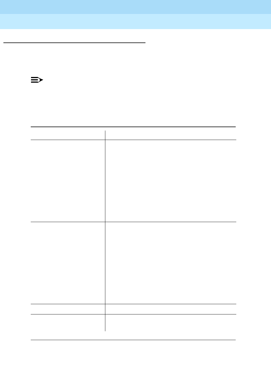
DEFINITYEnterpriseCommunicationsServerandSystem75andSystem85
Terminals and Adjuncts Reference
555-015-201 Issue 11
December 1999
The 8100 Series Telephones
16-22The 8110 and 8110M Telephones
16
Power Requirements
It is recommended that the 8110 and 8110M telephones have auxiliary power
(9V DC, 100 mA) to improve the performance of the speakerphone under the
following conditions: (See the table below.)
NOTE:
Use with the TN746 circuit pack requires auxiliary power (in the form of a
power adapter) at all loop lengths. On System 85 and DEFINITY G2, the line
must be administered as Data Restricted to allow for the automatic
disconnect feature.
Table 16-4. Power Requirements for the 8110 and 8110M Telephones
Circuit Pack Loop Information
If you are using:
Circuit Pack TN742
Circuit Pack TN769
■When loop length exceeds:
— 16,000 feet (22 gauge)
— 10,000 feet (24 gauge)
— 6,300 feet (26 gauge)
or
■When loop resistance exceeds 256 ohms
or
■When loop current is less than 26 mA
If you are using:
Circuit Pack SN229
■When loop length exceeds:
— 11,000 feet (22 gauge)
— 7,000 feet (24 gauge)
— 4,400 feet (26 gauge)
or
■When loop resistance exceeds 180 ohms
or
When loop current is less than 26 mA
Any installation When loop current is less than 26 mA
Any installation When another analog telephone is bridged with
the 8110 or 8110M telephone
DEFINITYEnterpriseCommunicationsServerandSystem75andSystem85
Terminals and Adjuncts Reference
555-015-201 Issue 11
December 1999
The 8100 Series Telephones
16-23The 8110 and 8110M Telephones
16
Switch Administration
The 8110 and 8110M telephones must be administered in the following ways:
■If the 8110 or 8110M telephone is connected to a System 75, DEFINITY
G1 or G3, or a DEFINITY ECS, it must be administered as a 2500 analog
telephone with Message Waiting.
■If the 8110 or 8110M telephone is connected to a System 85 or
DEFINITY G2, it can be administered as an analog line.
NOTE:
The programmable dialing buttons are programmed individually on the
telephone; they are
not
administrable from the switch.
Administration of Hidden Features
For procedures on administering the hidden features on the 8110M (
to be done
ONLY by the system administrator
)suchas:
■Reprogramming the Hold Feature
■Administering the Timed Disconnect Feature
■Locking the Programmable Dialing Buttons
Refer to the 8101, 8101M,
8102M and 8110M Telephones Quick Reference Guide
which comes in the box with the 8110M.
Power Failure Operation
The 8110 or 8110M telephone can be used as an emergency station during power
failure transfer conditions. If the telephone is over 3,000 feet from the cabinet, the
telephone will not work properly.
Ringer Equivalency Numbers
The Ringer Equivalency Number for the 8110 telephone is: 0.5A and 1.6B. For the
8110M telephone the Ringer Equivalency Number is: 0.6A and 1.6B.
FCC Registration
The 8110 and 8110M telephones are FCC registered (A5SUSA-18602-MT-E).
Hearing Aid Compatible
These telephones are compatible with the inductively coupled hearing aids
prescribed by the FCC.

DEFINITYEnterpriseCommunicationsServerandSystem75andSystem85
Terminals and Adjuncts Reference
555-015-201 Issue 11
December 1999
The 8100 Series Telephones
16-24The 8110 and 8110M Telephones
16
8110 and 8110M Telephones Equipment PECs and
Comcodes
The 8110 and 8110M telephones and components can be ordered with the
following PECs and Comcodes:
■Basic 8110 (8110A01A, 8110A01B, and 8110A01C) Telephone
PEC: 3193-001 (Black=COL09; White=COL10)
Comcode: Black=106272321; White=106272339
■Modified 8110M (8110A01D) Telephone
PEC: 3193-001 (Black=COL09; White=COL10)
Comcode: Black=107535841; White=107535858
■Handset
Comcode: Black=106050065; White=106053408
■Handset cord
Comcode: Black=105635429; White=105701809
■Line cord (7 feet)
Comcode: 103732541
■Line cord (14 feet, silver)
PEC: 2725-07N (COL18)
Comcode: 103786802
■Line cord (25 feet, silver)
PEC: 2725-07S (COL18)
Comcode: 103786828
■Button designation card
PEC: 31932 (Package of 25)
PEC: 31938 (Tractor Feed)
Single Sheet Comcode: 846562700
25 Sheets Comcode: 846562718
Tractor Feed Comcode: 846562726
■Designation card covers
PEC: 31937
Comcode: 106523236
■Repertory Dial buttons (Programmable dialing buttons)
(These buttons can be used to replace lost buttons or to replace the two
buttons removed for hotel/motel conversion.)
(Package of 80)
PEC: 31936
Comcode: 106503238

DEFINITYEnterpriseCommunicationsServerandSystem75andSystem85
Terminals and Adjuncts Reference
555-015-201 Issue 11
December 1999
The 8100 Series Telephones
16-25The 8110 and 8110M Telephones
16
■Security designation card and cover
(These cards and covers are for concealing the PROGRAM and PAUSE
buttons and the two topmost programmable dialing buttons so that
unauthorized changes cannot be made to the programmable dialing
assignments.) (Package of 25 cards and clear plastic designation card
covers)
PEC: 31931
Comcode: 106248370
■Stands
(These stands can be used to replace damaged or broken stands.)
(Package of 5)
PEC: 31933
Comcode: 106503204
■Speakerphone power adapter
(This local power is necessary when reaching limitations for loop length or
when using the TN746 circuit pack.)
PEC: 31930
Comcode: 106460470
■Auto-Answer buttons
(These buttons can be used to replace lost buttons or to restore the
Auto-Answer feature if it has been deactivated.)
(Package of 25)
PEC: 31935
Comcode: 106503212
■Auto Answer flat caps
(These caps are designed to cover the Auto-Answer button opening when
the Auto-Answer button has been removed.)
(Package of 25)
PEC: 31934
Comcode: 106503220
Adjuncts
AK-type Noisy Environment Handset (PEC: 31052A) can also be purchased
and connected to the 8110 or 8110M telephone.
NOTE:
Neither the 8110 nor the 8110M telephone has a connector for the S201A or
S203 Speakerphone or the 500A Headset Adapter.

DEFINITYEnterpriseCommunicationsServerandSystem75andSystem85
Terminals and Adjuncts Reference
555-015-201 Issue 11
December 1999
The 8100 Series Telephones
16-26The 8110 and 8110M Telephones
16
Additional Documents
The following documents contain additional information relating to the 8110 and
8110M telephones: (Use the 9-digit number listed after each document to order
the book from the BCS Publications Center.)
■
DEFINITY Communications System Generic 1, Generic 3, and System 75,
DEFINITY Generic 2 and System 85 8101, 8102, 8102M, 8110, 8110M
Telephones User’s Guide
, 555-230-774
The following instructions are shipped with every 8110 telephone:
■
8101, 8102, and 8110 Telephones User’s Manual
, 555-015-131
The following instructions are shipped with every 8110M telephone:
■
8101, 8101M, 8102M and 8110M Telephones Quick Reference Guide

ISDN Voice Terminals
17-1
17
DEFINITYEnterpriseCommunicationsServerandSystem75andSystem85
Terminals and Adjuncts Reference
555-015-201 Issue 11
December 1999
17
ISDN Voice Terminals
The following voice terminals described in this section are used with the
Integrated Services Digital Network (ISDN) communication system:
■ISDN 7505 modular voice terminal
■ISDN 7506 display terminal
■ISDN 7507 display terminal
■ISDN 8503T voice terminal
■ISDN 8510T voice/data terminal
■ISDN 8520T voice/data terminal
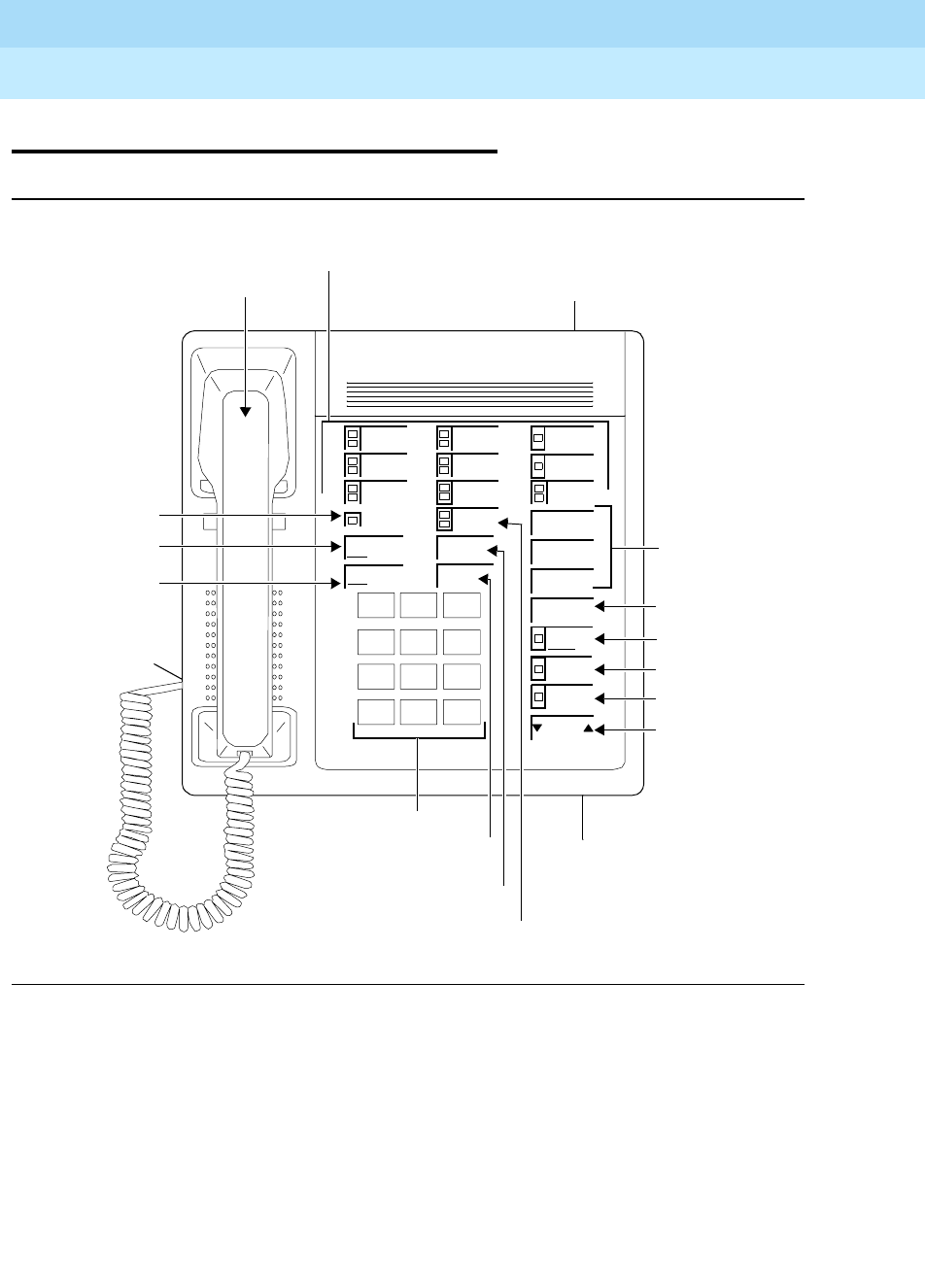
DEFINITYEnterpriseCommunicationsServerandSystem75andSystem85
Terminals and Adjuncts Reference
555-015-201 Issue 11
December 1999
ISDN Voice Terminals
17-2The ISDN 7505 Modular Terminal
17
The ISDN 7505 Modular Terminal
Figure 17-1. The 7505 Asynchronous Data Modular Terminal
Volume
123
456
789
ABC DEF
MNOJKLGHI
PRS TUV WXY
*
O#
Oper
Conference
Drop
Transfer
Hold
Message
ISDN 7505
Handset
Ring
Test
Shift
Select
Mute
Speaker
Redial
10 Call Appearance
Feature Buttons Line Jack
3 Shiftable
Feature
Buttons
Data/Send/Off Button
Transfer
Volume Control
Redial/Feature
Shift/Select
Mute Button
Speaker Button
Hold
Dial Pad
Drop/Test
Conference/
Ring Button
Message
Speakerphone/Headset
Button
Button
Handset Cord
Jack (under left
side of base)
Button
Light
(on back of
stand)
(used with optional ADM)
Adapter Jack (under base)
Button
Button
Button
DEFINITYEnterpriseCommunicationsServerandSystem75andSystem85
Terminals and Adjuncts Reference
555-015-201 Issue 11
December 1999
ISDN Voice Terminals
17-3The ISDN 7505 Modular Terminal
17
The 7505 Modular Terminal is used with the Integrated Services Digital Network
(ISDN) communication system through a 4-wire “T”-interface. The modular 7505
is a voice terminal when equipped with a Voice Only Module (VOM). As a
telephone, it offers programmable buttons, fixed feature buttons, a Message light,
touch-tone dialing, and a built-in, programmable speakerphone or SPOKESMAN
loudspeaker. The speakerphone can be programmed at the terminal by the user
for one of three states: On, Disabled, or SPOKESMAN loudspeaker. The 7505
can be equipped with an optional Asynchronous Data Module that provides the
user with simultaneous voice and data capabilities. The 7505 equipped with the
ADM offers the same voice capabilities as the 7505 equipped with the VOM, plus
it allows attached data terminals or personal computers to send and receive data
through the digital network.
NOTE:
The 7505 voice terminal is no longer being manufactured.
Applications
The 7505 modular terminal can be used with the DEFINITY Communications
System Generic 1, Generic 2, and Generic 3, and the DEFINITY ECS. Typical
applications of the 7505 are users requiring a large number of line appearances
with or without data capabilities.
Physical Description
Dimensions
NOTE:
The following dimensions for the 7505 terminal are approximate.
Width = 8-3/4 inches
Depth (front to back) = 8-1/2 inches
Height (maximum with handset in place) = 6-1/4 inches
Features
Eight Fixed Feature Buttons
The 7505 is equipped with eight fixed feature buttons. Three of the buttons are
dual purpose buttons that are used with the SELECT button to perform other
functions.
■CONFERENCE/RING button
■DROP/TEST button

DEFINITYEnterpriseCommunicationsServerandSystem75andSystem85
Terminals and Adjuncts Reference
555-015-201 Issue 11
December 1999
ISDN Voice Terminals
17-4The ISDN 7505 Modular Terminal
17
■TRANSFER button
■HOLD button
■SPEAKER button
■MUTE button
■REDIAL/or feature button
■SELECT button
Message Light
The red Message light goes on when a message is left for the user. It goes off
when the user retrieves the message.
Call Appearance/Feature buttons
The 7505 has nine or 10 call appearance buttons. These same 10 buttons, when
properly administered, can be used for activating features. One of these buttons is
used as a DATA/SEND/OFF button if the set has data capability.
Feature-Only Button
The 7505 has three buttons that are used for features. When used with the
SELECT button these buttons can be used for three additional custom features. In
addition to these three buttons, the REDIAL button provides another custom
feature button.
Self-Test
The 7505 has a local self-test. When used with the SELECT button, the
DROP/TEST button begins and ends the self-test.
MUTE button
Pressing the MUTE button mutes the handset or the speakerphone, whichever is
active. The red light next to the MUTE button goes on. The user is placed in a
listen-only mode.
Loudspeaker
The 7505 has a built-in, programmable SPOKESMAN loudspeaker. The
SPEAKER button is used to turn the loudspeaker on and off. The Volume arrow
buttons control the volume of the loudspeaker.
Speakerphone
The 7505 has a built-in, programmable speakerphone. The SPEAKER button is
used to turn the speakerphone on and off. The green light next to the SPEAKER
button goes on when the speakerphone is on. The Volume arrow buttons control
the volume of the speakerphone.

DEFINITYEnterpriseCommunicationsServerandSystem75andSystem85
Terminals and Adjuncts Reference
555-015-201 Issue 11
December 1999
ISDN Voice Terminals
17-5The ISDN 7505 Modular Terminal
17
Other Physical Features
Handset
The 7505 is equipped with an R-type handset.
Dial pad
The 7505 has a 12-button touch-tone dial pad.
Jacks
The 7505 housing contains three jacks. The Handset jack is located on the bottom
of the 7505 and can be identified by the adjacent handset symbol. The Line jack is
located on the back of the 7505. The Adjunct jack, used for connection to the
optional adjuncts, is located on the bottom of the terminal and can be identified by
the adjacent speaker symbol. If the optional ADM is provided, there is an EIA
RS-232D Interface connector provided on its back.
Cords
Two cords are supplied with the 7505: a coiled 9-foot modular handset cord and a
line cord. An optional 12-foot handset cord is available.
Ringing
The 7505 has electronic tone ringing with patterns that can be selected by using
the SELECT and CONFERENCE/RING buttons. The volume is controlled by the
volume “arrow” buttons.
Mounting Options
The 7505 comes equipped with a non-adjustable desk stand.
Color Options
The base of the 7505 is always black. The top of the 7505 is available in misty
cream or black.
Distance Limitations
The maximum signaling distance from the port board to the work location jack
based on DIW 24 AWG cable is:
■Terminating resistor in work location — 1900 feet
■Terminating resistor in satellite closet — 1600 feet

DEFINITYEnterpriseCommunicationsServerandSystem75andSystem85
Terminals and Adjuncts Reference
555-015-201 Issue 11
December 1999
ISDN Voice Terminals
17-6The ISDN 7505 Modular Terminal
17
Power Requirements
The 7505 requires an auxiliary power supply. The power supply can be provided
at a central location or may be collocated with the 7505. If the auxiliary power
supply fails or loses its power, the 7505 will provide basic voice service with the
phantom power provided by the switch.
Terminating Resistor
A 440A4 Terminating Resistor adapter is required with the 7505. The 440A4 can
be located at the work location or in the satellite closet.
Power Failure Operation
The 7505 cannot be used as an emergency station during power failure transfer
conditions.
FCC Registration
The 7505 modular terminal is not FCC registered.
Hearing Aid Compatible
This voice terminal is compatible with the inductively coupled hearing aids
prescribed by the FCC.
7505 Equipment PECs
The 7505 modular terminal and optional components were ordered with the
following PECs:
■ISDN 7505 Voice Only Modular Terminal — 3195-VOM
■ISDN 7505 Asynchronous Data Modular Terminal — 3195-ADM
■440A4 Terminating Resistor — 2709-A59
■ADM Upgrade Kit — 31955
■VOM Feature Package 2 Upgrade Kit — 31969
■ADM Feature Package 2 Upgrade Kit — 31970

DEFINITYEnterpriseCommunicationsServerandSystem75andSystem85
Terminals and Adjuncts Reference
555-015-201 Issue 11
December 1999
ISDN Voice Terminals
17-7The ISDN 7505 Modular Terminal
17
Adjuncts
The following adjuncts can be used with the 7505 modular terminal:
■500A Headset Adapter (and a standard headset; see “Headsets” below)
■S101A Speakerphone
■S201A Speakerphone
Headsets
A list of compatible headsets, consisting of both modular and plug prong base
units and selection of headpieces, appears in “Headset Adapters” in the Adjuncts
section later in this manual.
Additional Documents
The following documents contain additional information relating to the 7505
modular terminal:
■
DEFINITY Generic 1 7505, 7506, and 7507 Voice Terminal User’s Guide
,
555-204-750
■
DEFINITY Generic 2 ISDN 7505, 7506, and 7507 Terminal User’s Guide
,
555-104-719
■
ISDN 7505 Modular Terminal and ISDN 7506 Display Terminal User’s
Manual
, 555-021-714
■
ISDN 7505 Asynchronous Data Module User’s Guide
, 555-021-716
■
Integrated Services Digital Network (ISDN) Terminal Installation and Test
User’s Manual
, 555-021-101
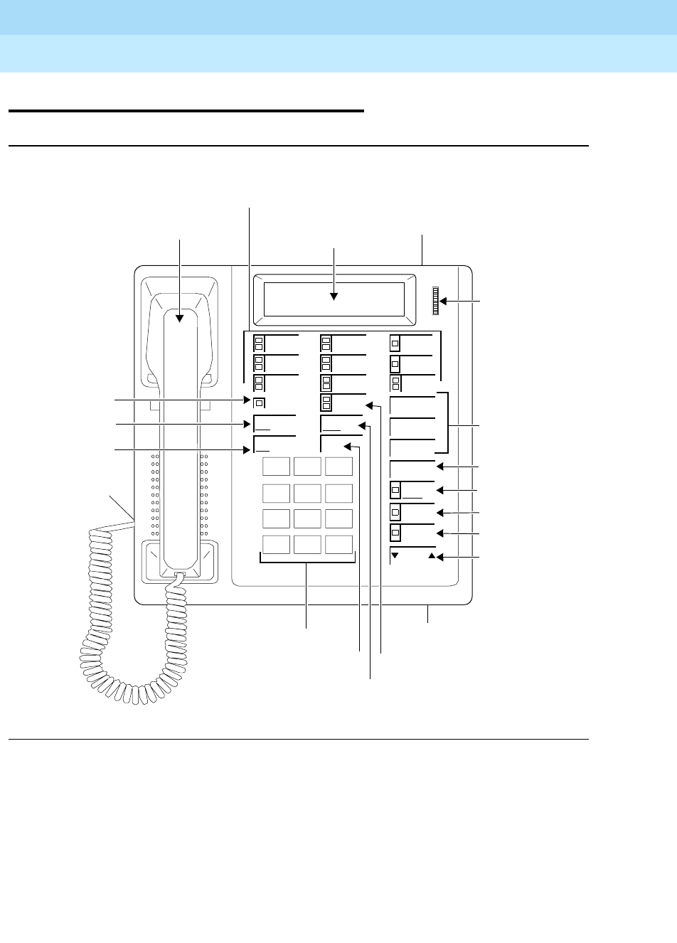
DEFINITYEnterpriseCommunicationsServerandSystem75andSystem85
Terminals and Adjuncts Reference
555-015-201 Issue 11
December 1999
ISDN Voice Terminals
17-8The ISDN 7506 Voice Terminal
17
The ISDN 7506 Voice Terminal
Figure 17-2. The 7506 Asynchronous Data Modular Display Terminal
Volume
123
456
789
ABC DEF
MNOJKLGHI
PRS TUV WXY
*
O#
Oper
Conference
Drop
Transfer
Hold
Message
ISDN 7506
Display
Handset
Ring
Test
Clock
Shift
Select
Mute
Speaker
Redial
10 Call Appearance
Feature Buttons
Display
Line Jack
3 Shiftable
Feature
Buttons
Data/Send/Off Button
Transfer/Clock Button
Volume Control
Redial/Feature
Shift/Select
Mute Button
Hold Button
Dial Pad
Drop/Test
Button
Conference/
Ring Button
Message Light
Speakerphone/Headset
Handset Cord
Jack (under left
side of base)
Adapter Jack (under base)
(used with optional ADM)
Contrast
Control
Button
Button
Button
Speaker Button
(on back of
stand)
DEFINITYEnterpriseCommunicationsServerandSystem75andSystem85
Terminals and Adjuncts Reference
555-015-201 Issue 11
December 1999
ISDN Voice Terminals
17-9The ISDN 7506 Voice Terminal
17
The 7506 Display terminal is used with the Integrated Services Digital Network
(ISDN) communication system through a 4-wire “T”-interface. The modular 7506
is a voice terminal when equipped with a Voice Only Module (VOM). As a
telephone, it offers programmable buttons, fixed feature buttons, a Message light,
touch-tone dialing, and a built-in, programmable speakerphone or SPOKESMAN
loudspeaker. The speakerphone can be programmed at the terminal by the user
for one of three states: On, Disabled, and SPOKESMAN loudspeaker. The 7506
can be equipped with an optional Asynchronous Data Module that provides the
user with simultaneous voice and data capabilities. The 7506 equipped with the
ADM offers the same voice capabilities as the 7506 equipped with the VOM, plus
it allows attached data terminals or personal computers to send and receive
asynchronous data through the digital network. Both versions of the 7506 display
terminal are equipped with a two-line, 24-character display.
NOTE:
The 7506 voice terminal is no longer being manufactured.
Applications
The 7506 display terminal can be used with the DEFINITY Communications
System Generic 1, Generic 2, and Generic 3, and the DEFINITY ECS. Typical
applications of the terminal are users requiring a large number of line
appearances with or without data. It is particularly useful for middle managers.
Physical Description
Dimensions
NOTE:
The following dimensions for the 7506 terminal are approximate.
Width = 8-3/4 inches
Depth (front to back) = 8-1/2 inches
Height (maximum with handset in place) = 6-1/4 inches

DEFINITYEnterpriseCommunicationsServerandSystem75andSystem85
Terminals and Adjuncts Reference
555-015-201 Issue 11
December 1999
ISDN Voice Terminals
17-10The ISDN 7506 Voice Terminal
17
Features
Eight Fixed Feature Buttons
The 7506 display terminal is equipped with eight fixed feature buttons. Four of the
buttons are dual purpose buttons that are used with the SELECT button to
perform other functions.
■CONFERENCE/RING button
■DROP/TEST button
■TRANSFER/CLOCK button
■SPEAKER button
■MUTE button
■REDIAL/or feature button
■SELECT button
Message Light
The red Message light goes on when a message is left for the user. It goes off
when the user retrieves the message.
Call Appearance/Feature buttons
The 7506 display terminal has nine or 10 call appearance buttons. These same 10
buttons, when properly administered, can be used for activating features. One of
these buttons is used as a DATA/SEND/OFF button if the set has data capability.
Feature Button
The 7506 display terminal has three buttons that are used for features. When
used with the SELECT button, these buttons can be used for three additional
custom features. In addition to these buttons, the REDIAL button provides another
custom feature button.
Display
Information shown on the display include the number being dialed, the time and
date, and information concerning incoming calls and message retrieval. The
viewing contrast is adjusted with the Display Contrast Control wheel located to the
rightofthedisplay.
Self-Test
The 7506 display terminal has a local self-test. When used with the SELECT
button, the DROP/TEST button begins and ends the self-test.

DEFINITYEnterpriseCommunicationsServerandSystem75andSystem85
Terminals and Adjuncts Reference
555-015-201 Issue 11
December 1999
ISDN Voice Terminals
17-11The ISDN 7506 Voice Terminal
17
Loudspeaker
The 7506 display terminal has a built-in, programmable SPOKESMAN
loudspeaker. The SPEAKER button is used to turn the loudspeaker on and off.
The volume arrow buttons control the volume of the loudspeaker.
Speakerphone
The 7506 display terminal has a built-in, programmable speakerphone. The
SPEAKER button is used to turn the speakerphone on and off. The green light
next to the SPEAKER button goes on when the speakerphone is active. The
volume arrow buttons control the volume of the speakerphone.
MUTE button
Pressing the MUTE button mutes the handset or the speakerphone, whichever is
active. The red light next to the MUTE button goes on. The user is placed in a
listen-only mode.
Other Physical Features
Handset
The 7506 is equipped with an R-type handset.
Dial pad
The 7506 has a 12-button touch-tone dial pad.
Jacks
The 7506 housing contains three jacks. The Handset jack is located on the bottom
of the 7506 terminal. The Line jack is located on the back of the 7506 terminal.
The Adjunct jack, used for connection to the optional adjuncts, is located on the
bottom of the terminal. If the optional ADM is provided, there is an EIA RS-232D
Interface connector provided on its back.
Cords
Two cords are supplied with the terminal: a coiled 9-foot modular handset cord
and a line cord. An optional 12-foot handset cord is available.
Ringing
The 7506 display terminal has electronic tone ringing with patterns that can be
selected by using the SELECT and CONFERENCE/RING buttons in sequence.
The volume is controlled by the volume arrow buttons.
Mounting Options
The 7506 display terminal comes equipped with a nonadjustable desk stand.

DEFINITYEnterpriseCommunicationsServerandSystem75andSystem85
Terminals and Adjuncts Reference
555-015-201 Issue 11
December 1999
ISDN Voice Terminals
17-12The ISDN 7506 Voice Terminal
17
Color Options
The base of the 7506 is always black. The top of the 7506 is available in misty
cream or black.
Distance Limitations
The maximum signaling distance from the port board to the work location jack
based on DIW 24 AWG cable is:
■Terminating resistor in work location — 1900 feet
■Terminating resistor in satellite closet — 1600 feet
Power Requirements
The 7506 display terminal requires an auxiliary power supply. The power supply
can be provided at a central location or may be collocated with the 7506 display
terminal. If the auxiliary power supply fails or loses its power, the 7506 display
terminal will provide basic voice service with the phantom power provided by the
switch.
Terminating Resistor
A 440A4 Terminating Resistor adapter is required with the 7506 display terminal.
The 440A4 can be located at the work location or in the satellite closet.
Power Failure Operation
The 7506 display terminal cannot be used as an emergency station during power
failure transfer conditions.
FCC Registration
The 7506 display terminal is not FCC registered.
Hearing Aid Compatible
This voice terminal is compatible with the inductively coupled hearing aids
prescribed by the FCC.

DEFINITYEnterpriseCommunicationsServerandSystem75andSystem85
Terminals and Adjuncts Reference
555-015-201 Issue 11
December 1999
ISDN Voice Terminals
17-13The ISDN 7506 Voice Terminal
17
7506 Equipment PECs
The 7506 display terminal and optional components were ordered with the
following PECs:
■ISDN 7506 Voice Only Modular Display Terminal — 3196-VOM
■ISDN 7506 Asynchronous Data Modular Display Terminal — 3196-ADM
■440A4 Terminating Resistor — 2709-A59
■ADM Upgrade Kit — 31955
■VOM Feature Package 2 Upgrade Kit — 31969
■ADM Feature Package 2 Upgrade Kit — 31970
Adjuncts
The following adjunct can be used with the 7506 display terminal:
■500A Headset Adapter (and a standard headset; see “Headsets” below)
■S101A Speakerphone
■S201A Speakerphone
Headsets
A list of compatible headsets, consisting of both modular and plug prong base
units and selection of headpieces, appears in “Headset Adapters” in the Adjuncts
section later in this manual.
Additional Documents
The following documents contain additional information relating to the
7506 display terminal:
■
DEFINITY Generic 1 7505, 7506, 7507 Voice Terminals User’s Guide
,
555-204-750
■
DEFINITY Generic 2 ISDN 7505, 7506, 7507 Terminal User’s Guide
,
555-104-719
■
ISDN 7505 Modular Terminal and ISDN 7506 Display Terminal User’s
Guide
, 555-021-714
■
ISDN 7506 Asynchronous Data Module User’s Guide
, 555-021-716
■
Integrated Services Digital Network (ISDN) Terminal Installation and Test
User’s Manual
, 555-021-101
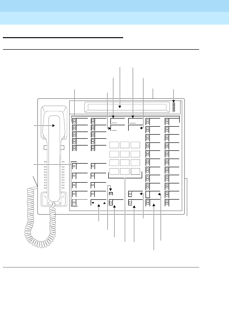
DEFINITYEnterpriseCommunicationsServerandSystem75andSystem85
Terminals and Adjuncts Reference
555-015-201 Issue 11
December 1999
ISDN Voice Terminals
17-14The ISDN 7507 Display Terminal
17
The ISDN 7507 Display Terminal
Figure 17-3. The 7507 Asynchronous Data Modular Display Terminal
Volume
123
456
789
ABC DEF
MNOJKLGHI
PRS TUV WXY
*
O#
Oper
Conference
Drop
Transfer
Hold
Speaker
Select
Mute
Message
Conference/Ring Button
Ring
Test
ISDN
7507
Drop/Test Button
Display Transfer/Clock Button
Hold Button
Clock
Speaker Button
Message Light
Volume Control Button
Dial Pad Mute
Select
Button
Line Jack Display
Speakerphone/
Headset
Adapter Jack
(in well under
Data/Send/Off Button
9Feature
Buttons
Handset
Cord Jack
Handset
31 Call Appearance/
Feature Buttons
Redial
Button
(under base)
base)
Redial Button
(usedwithoptionalADM)
Contrast
Controlof stand)
(on back
DEFINITYEnterpriseCommunicationsServerandSystem75andSystem85
Terminals and Adjuncts Reference
555-015-201 Issue 11
December 1999
ISDN Voice Terminals
17-15The ISDN 7507 Display Terminal
17
The 7507 Display terminal is used with the Integrated Services Digital Network
(ISDN) communication system through a 4-wire “T”-interface. The modular 7507
is a voice terminal when equipped with a Voice Only Module (VOM). As a
telephone it offers programmable buttons, fixed feature buttons, Message light,
touch-tone dialing, and a built-in, programmable speakerphone or SPOKESMAN
loudspeaker. The speakerphone can be programmed at the terminal by the user
for one of three states: On, Disabled, and SPOKESMAN loudspeaker. The 7507
can be equipped with an optional Asynchronous Data Module that provides the
user with simultaneous voice and data capabilities. The 7507 equipped with the
ADM offers the same voice capabilities as the 7507 equipped with the VOM, plus
it allows attached data terminals or personal computers to send and receive data
through the digital network. The terminal is equipped with a 2-line, 40-character
display.
NOTE:
The 7507 voice terminal is no longer being manufactured.
Applications
The 7507 display terminal can be used with the DEFINITY Communications
System Generic 1, Generic 2, and Generic 3, and the DEFINITY ECS. Typical
applications of the display terminal are users requiring a large number of line
appearances with or without data capabilities. It is particularly useful for
secretary/receptionist positions and executives.
Physical Description
Dimensions
NOTE:
The following dimensions for the 7507 terminal are approximate.
Width = 12 inches
Depth (front to back) = 8-3/4 inches
Height (maximum with handset in place) = 5-1/4 inches

DEFINITYEnterpriseCommunicationsServerandSystem75andSystem85
Terminals and Adjuncts Reference
555-015-201 Issue 11
December 1999
ISDN Voice Terminals
17-16The ISDN 7507 Display Terminal
17
Features
Eight Fixed Feature Buttons
The 7507 display terminal is equipped with eight fixed feature buttons. Three of
the buttons are dual purpose buttons that are used with the SELECT button to
perform other functions.
■CONFERENCE/RING button
■DROP/TEST button
■TRANSFER/CLOCK button
■HOLD button
■SPEAKER button
■MUTE button
■REDIAL button
■SELECT button
Message Light
The red Message light goes on when a message is left for the user. It goes off
when the user retrieves the message.
Call Appearance/Feature buttons
The 7507 display terminal has 30 or 31 call appearance buttons. These same 31
buttons, when properly administered, can be used for activating features. One of
these buttons is used as a DATA/SEND/OFF button if the set has data capability.
Feature Button
The 7507 display terminal has nine buttons that are used for features. When used
with the SELECT button, these buttons can be used for nine additional custom
features. In addition to these buttons, the REDIAL button provides another custom
feature button.
Display
Information shown on the display include the number being dialed, the time and
date, and information concerning incoming calls and message retrieval. The
viewing contrast is adjusted with the Display Contrast Control wheel located to the
rightofthedisplay.
Self-Test
The 7507 display terminal has a local self-test. When used with the SELECT
button, the DROP/TEST button begins and ends the self-test.

DEFINITYEnterpriseCommunicationsServerandSystem75andSystem85
Terminals and Adjuncts Reference
555-015-201 Issue 11
December 1999
ISDN Voice Terminals
17-17The ISDN 7507 Display Terminal
17
Loudspeaker
The 7507 display terminal has a built-in, programmable SPOKESMAN
loudspeaker. The SPEAKER button is used to turn the loudspeaker on and off.
The Volume arrow buttons control the volume of the loudspeaker.
Speakerphone
The 7507 display terminal has a built-in, programmable speakerphone. The
SPEAKER button is used to turn the speakerphone on and off. The green light
next to the SPEAKER button goes on when the speakerphone is active. The
Volume arrow buttons control the volume of the speakerphone.
MUTE button
Pressing the MUTE button mutes the handset or the speakerphone, whichever is
active. The red light next to the MUTE button goes on. The user is placed in a
listen-only mode.
Other Physical Features
Handset
The 7507 display terminal is equipped with an R-type handset.
Dial pad
The 7507 display terminal has a 12-button touch-tone dial pad.
Jacks
The 7507 display terminal housing contains three jacks. The Handset jack is
located on the bottom of the terminal and can be identified by the adjacent
handset symbol. The Line jack is located on the back of the terminal. The Adjunct
jack, used for connection to the optional adjuncts, is located on the bottom of the
terminal and can be identified by the adjacent speaker symbol. If the optional
ADM is provided, there is an EIA RS-232D Interface connector provided on its
base.
Cords
Two cords are supplied with the 7507 display terminal: a coiled 9-foot modular
handset cord and a line cord. An optional 12-foot handset cord is available.
Ringing
The 7507 display terminal has electronic tone ringing with patterns that can be
selected by using the SELECT and CONFERENCE/RING buttons in sequence.
The volume is controlled by the Volume arrow buttons.
Mounting Options
The 7507 display terminal comes equipped with a nonadjustable desk stand.

DEFINITYEnterpriseCommunicationsServerandSystem75andSystem85
Terminals and Adjuncts Reference
555-015-201 Issue 11
December 1999
ISDN Voice Terminals
17-18The ISDN 7507 Display Terminal
17
Color Options
The base of the 7507 display terminal is always black. The top of the 7507 display
terminal is available in misty cream or black.
Distance Limitations
The maximum signaling distance from the port board to the work location jack
based on DIW 24 AWG cable is:
■Terminating resistor in work location—1900 feet
■Terminating resistor in satellite closet—1600 feet
Power Requirements
The 7507 display terminal requires an auxiliary power supply. The power supply
can be provided at a central location or may be collocated with the 7507 display
terminal. If the auxiliary power supply fails or loses its power, the 7507 display
terminal will provide basic voice service with the phantom power provided by the
switch.
Terminating Resistor
A 440A4 Terminating Resistor adapter is required with the 7507 display terminal.
The 440A4 can be located at the work location or in the satellite closet.
Power Failure Operation
The 7507 display terminal cannot be used as an emergency station during power
failure transfer conditions.
FCC Registration
The 7507 display terminal is not FCC registered.
Hearing Aid Compatible
This voice terminal is compatible with the inductively coupled hearing aids
prescribed by the FCC.

DEFINITYEnterpriseCommunicationsServerandSystem75andSystem85
Terminals and Adjuncts Reference
555-015-201 Issue 11
December 1999
ISDN Voice Terminals
17-19The ISDN 7507 Display Terminal
17
7507 Equipment PECs
The 7507 display terminal and optional components were ordered with the
following PECs:
■ISDN 7507 Voice Only Modular Display Terminal — 3197-VOM
■ISDN 7507 Asynchronous Data Modular Display Terminal — 3197-ADM
■440A4 Terminating Resistor — 2709-A59
■ADM Upgrade Kit — 31955
■VOM Feature Package 2 Upgrade Kit — 31969
■ADM Feature Package 2 Upgrade Kit — 31970
Adjuncts
The following adjunct can be used with the 7507 display terminal:
■500A Headset Adapter (and a standard headset; see “Headsets” below)
■S101A Speakerphone
■S201A Speakerphone
Headsets
A list of compatible headsets, consisting of both modular and plug prong base
units and selection of headpieces, appears in “Headset Adapters” in the Adjuncts
section later in this manual.
Additional Documents
The following documents contain additional information relating to the 7507
Display terminal:
■
DEFINITY Generic 1 7505, 7506, 7507 Voice Terminals User’s Guide,
555-204-750
■
DEFINITY Generic 2 ISDN 7505, 7506 7507 Terminal User’s Guide
,
555-104-709
■
ISDN 7507 Display Terminal User’s Manual
, 555-021-715
■
ISDN 7507 Asynchronous Data Module User’s Guide
, 555-021-716
■
Integrated Services Digital Network (ISDN) Terminal Installation and Test
User’s Manual
, 555-021-101
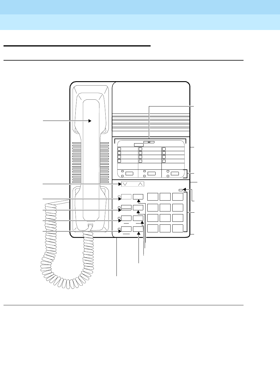
DEFINITYEnterpriseCommunicationsServerandSystem75andSystem85
Terminals and Adjuncts Reference
555-015-201 Issue 11
December 1999
ISDN Voice Terminals
17-20The ISDN 8503 Voice Terminal
17
The ISDN 8503 Voice Terminal
Figure 17-4. The Desk-mounted ISDN 8503T Voice Terminal
Message
123
456
789
ABC DEF
MNOJKLGHI
PQRS TUV WXYZ
*
O#
OPER
ISDN 8503T
Dial Pad/
Handset Cord Jack
Handset
Hold Button
Redial Button
Memory Button
Drop/Test Button
Volume
Volume
Mute Redial
Program Memory
Conf Drop
Transfer Hold
TestRing
Pause
ab c
4
3
2
1
8
7
6
5
#
*
0
9
Press Memory button, then dialpad button
Designation
Line Jack
3Call
Memory-Dialing
Adjunct Jack
(on back of
voice terminal)
Message Light
(on back of voice terminal)
Mute Button
Program
Conference/
Ring Button
Transfer/
(on back of
voice terminal)
Button
Control
Button
Pause
Button
Feature Buttons
Appearance/
Card
Locations
Desk Stand
(on bottom of
terminal)

DEFINITYEnterpriseCommunicationsServerandSystem75andSystem85
Terminals and Adjuncts Reference
555-015-201 Issue 11
December 1999
ISDN Voice Terminals
17-21The ISDN 8503 Voice Terminal
17
The 8503T voice terminal is a non-modular set used with the ISDN
communication system through a 4-wire “T”-interface. This voice terminal offers
the following: four standard fixed feature buttons, a Message light, three call
appearance/flexible feature buttons, each with a red and green light, 12
programmable memory-dialing locations on the dial pad keys, a PROGRAM
button for storing numbers at the memory-dialing locations and a MEMORY
button for dialing these programmed numbers or codes, the Redial feature, the
Mute feature, eight possible personalized ringing patterns selected with the Select
Ring feature, high fidelity audio capabilities (bandwidth from.3 to 3.8 kHz) with the
K-type handset, and touch-tone dialing. This set does not provide data
capabilities.
Applications
The 8503T voice terminal can be used with the DEFINITY Communications
System Generic 2 and Generic 3, and the DEFINITY ECS. Typical applications of
the 8503T voice terminal are users handling a low volume of voice-only calls, staff
workers and lower level managers, as well as lobbies and conference rooms.
Physical Description
Dimensions
NOTE:
The dimensions given here for the 8503T voice terminal are approximate.
Width = 7-3/4 inches
Depth (front to back) = 9-1/2 inches
Height (maximum with handset in place)
The desk-mounted model = 5-1/4 inches
The wall-mounted model = 4-1/2 inches
Features
Four Standard Fixed Features
■CONF/RING button
■DROP/TEST button
■TRANSFER/PAUSE button
■HOLD button

DEFINITYEnterpriseCommunicationsServerandSystem75andSystem85
Terminals and Adjuncts Reference
555-015-201 Issue 11
December 1999
ISDN Voice Terminals
17-22The ISDN 8503 Voice Terminal
17
Message Light
The red Message light goes on when a message is left for the user. This light
goes off when the user retrieves the message.
Call Appearance/Feature buttons
The 8503T voice terminal has three call appearance/flexible feature buttons, each
with a red light and a green status light. Although the buttons can accommodate
either
call appearances or administered features, it is highly suggested that all
three of these call appearance/feature buttons be used for call appearances.
Twelve Programmed Memory Locations
The dial pad can be used for storing and dialing frequently dialed telephone
numbers, emergency numbers, or feature access codes. In order to store these
numbers or codes at each of the 12 memory-dialing locations, the user presses
the PROGRAM button, dials the telephone number to be stored, presses the
MEMORY button, and then the appropriate dial pad key (1 through 9, 0, *, and #).
To dial the number, the user presses the MEMORY button and the dial pad key
where that number is stored. Up to 16 digits can be stored at a memory-dialing
location.
PROGRAM button
The PROGRAM button can be used in three different ways: (When the voice
terminal is in program mode, the red light beside the PROGRAM button is on.)
■Used to enter programming mode and store frequently dialed telephone
numbers, emergency numbers, or feature access codes on each of the 12
dial pad keys (memory-dialing locations).
NOTE:
The user can press the TRANSFER/PAUSE button, while the voice
terminal is in program mode, to insert a one and one half-second
pause/delay in the telephone number to be stored in a
memory-dialing location. For example, the user might place a one
and one half-second pause between the dialing access code (such
as 9) and the outside telephone number.
■Used with the CONF/RING button to select one of eight possible
personalized ringing patterns
■Used with the DROP/TEST button to initiate a self-test of the voice terminal
lights and ringer
NOTE:
If the user picks up on an incoming call while the voice terminal is in
program mode, the voice terminal will automatically exit program
mode.

DEFINITYEnterpriseCommunicationsServerandSystem75andSystem85
Terminals and Adjuncts Reference
555-015-201 Issue 11
December 1999
ISDN Voice Terminals
17-23The ISDN 8503 Voice Terminal
17
MEMORY button
When the user presses the MEMORY button and one of the 12 dial pad keys
(memory-dialing locations), while off-hook, the voice terminal automatically dials
the number or access code stored on that dial pad key.
The user can clear a memory-dialing location by entering program mode, and
then pressing the MEMORY button and the appropriate dial pad key on which the
number or code is stored.
REDIAL button
With the Redial feature, the user can redial the telephone number last dialed from
the dial pad. (The handset must be off-hook.) Up to 37 digits can be redialed.
MUTE button
While on a call, the user can press the MUTE button (the red light next to the
button goes on), so the user can converse with someone in the same room
without the other party hearing the conversation. The user is placed in listen-only
mode. To disable the feature, the user presses the MUTE button a second time.
(The red light goes off.)
Volume control button
When the user is on a call, the Volume “arrow” button raises or lowers the volume
on the handset. When the handset is on-hook, this button raises or lowers the
ringer volume.
Self-Test
The 8503T voice terminal is equipped with a Self-Test feature. When the user
presses the PROGRAM button and then the DROP/TEST button, while on-hook,
the user can test the button lights and the ringer.
Other Physical Features
Handset
The 8503T voice terminal is equipped with a K-type wideband handset. With the
8503T voice terminal, this handset has high fidelity audio capabilities.
A K-type Noisy Environment Handset (PEC: 31052A) can also be purchased and
connected to the 8503T voice terminal.
Dial pad
The 8503T voice terminal is equipped with a standard 12-button touch-tone dial
pad for dialing telephone numbers or accessing features.
The dial pad keys can also be used as memory-dialing locations. By pressing the
PROGRAM button to enter program mode, the user can store a programmed

DEFINITYEnterpriseCommunicationsServerandSystem75andSystem85
Terminals and Adjuncts Reference
555-015-201 Issue 11
December 1999
ISDN Voice Terminals
17-24The ISDN 8503 Voice Terminal
17
number or access code on each of the 12 dial pad keys (memory-dialing
locations). With the MEMORY button, the user can dial these programmed
numbers.
Ringing
The 8503T voice terminal has electronic tone ringing with eight possible
personalized ringing patterns that can be selected by pressing the PROGRAM
button and then the CONF/RING button, while on-hook. Ringer volume is
controlled by the Volume “arrow” button when the voice terminal is on-hook.
Jacks
The 8503T voice terminal housing contains three jacks. The Handset cord jack,
for connecting the handset to the voice terminal, is located on the bottom of the
housing, near the front of the voice terminal. The Line jack, for connecting the line
cord to the voice terminal, is located on the bottom (left center) of the voice
terminal. The Adjunct jack, which is located on the bottom of the voice terminal
directly below the Line jack, is used for connecting optional adjunct equipment
such as an S201A Speakerphone or a 500A Headset Adapter to the voice
terminal.
Cords
Two cords are supplied with the 8503T voice terminal: a coiled 9-foot modular
Handset cord and a 7-foot Line cord. An optional 12-foot Handset cord is
available.
ROM cartridge
A ROM cartridge is installed in each voice terminal, but is easily removed and
replaced so that the firmware can always be updated. The cartridge can be
removed from the bottom of the housing by pressing the tab on the cartridge and
then lifting it from the housing. The cartridge can be inserted into the housing by
pressing the tab on the cartridge and then pressing it down into the bottom of the
housing.
Mounting Options
The 8503T voice terminal comes equipped with a desk stand. However, the desk
stand can be removed, and the voice terminal can be mounted on the wall.
Color Options
The 8503T voice terminal is available in black or in white.

DEFINITYEnterpriseCommunicationsServerandSystem75andSystem85
Terminals and Adjuncts Reference
555-015-201 Issue 11
December 1999
ISDN Voice Terminals
17-25The ISDN 8503 Voice Terminal
17
Distance Limitations
For a DEFINITY G2 and G3 and a DEFINITY ECS, in which multipoint
configuration is used, the maximum signaling distance possible from the port
board to the work location jack is: (The terminating resistor should be within 250
feet of the work location; the distances listed are applicable for up to two voice
terminals.)
■If 24 AWG cable is used = 1600 feet
■If 26 AWG cable is used = 1330 feet
Power Requirements
Phantom or Auxiliary Power
The 8503T voice terminal can receive power from the switch or from an auxiliary
power supply. The installer can select the type of power used by setting two
jumpers on the bottom of the voice terminal under a sliding plate between the Line
jack and the Adjunct jack. A pictorial representation of the jumpers is located to
the right of the sliding plate. These jumpers are labeled PHAN (phantom power)
and AUX (auxiliary power). The voice terminal is shipped in the PHAN position.
You must verify that the jumper settings are set correctly for your configuration.
NOTE:
The power jumpers must be set
only
by qualified service personnel.
■PHAN (phantom power) should be selected when power is provided by the
PBX. When the jumpers are set to PHAN, less than one Watt of power will
be drawn from the switch to support normal operation.
■AUX (auxiliary power) should be selected when power is provided in the
closet. When the jumpers are set to AUX, the 8503T voice terminal will
operate on a nominal 40 or 48 Vdc, UL-listed Communications Circuit
Power source.
DEFINITYEnterpriseCommunicationsServerandSystem75andSystem85
Terminals and Adjuncts Reference
555-015-201 Issue 11
December 1999
ISDN Voice Terminals
17-26The ISDN 8503 Voice Terminal
17
Terminating Resistors
The terminating resistor jumpers are located on the bottom of the voice terminal
under a sliding plate between the Line jack and Adjunct jack. These jumpers
enable (ON) or bypass (OFF) the terminating resistor. The set is shipped with the
jumpers in the OFF position bypassing the terminating resistor. You must verify
that the jumper settings are set correctly for your configuration.
NOTE:
The terminating resistor jumpers must be set
only
by qualified service
personnel.
■The terminating resistor jumpers must be set to OFF when the set is in a
point-to-point configuration and the terminating resistor is in the closet or a
440A4 is connected on the line.
■The terminating resistor jumpers must be set to ON when the set is in a
point-to-point configuration and the terminating resistor is
not
in the closet
or a 440A4 is
not
connected to the line.
■The terminating resistor jumpers must be set to OFF when the set is in a
multipoint configuration and the terminating resistor is in the closet, a
440A4 is connected on the line, or the jumper is set to ON in one of the
other sets on the line.
■The terminating resistor jumpers must be set to ON when the set is in a
multipoint configuration and the terminating resistor is
not
in the closet, a
440A4 is not connected on the line, or the jumper is not set to ON in any of
the other sets on the line.
Switch Administration
The 8503T voice terminal should be administered as an ISDN 7505 voice
terminal.
NOTE:
The three call appearance/feature buttons can be used for call appearances
or features, but, for most effective use of the voice terminal, it is strongly
suggested that all three buttons be administered for call appearances.
Power Failure Operation
The 8503T voice terminal cannot be used as an emergency station during power
failure transfer conditions.
FCC Registration
The 8503T voice terminal is FCC registered.

DEFINITYEnterpriseCommunicationsServerandSystem75andSystem85
Terminals and Adjuncts Reference
555-015-201 Issue 11
December 1999
ISDN Voice Terminals
17-27The ISDN 8503 Voice Terminal
17
Hearing Aid Compatible
This voice terminal is compatible with the inductively coupled hearing aids
prescribed by the FCC.
8503T Equipment PECs and Comcodes
The 8503T voice terminal and optional components can be ordered with the
following PECs and Comcodes:
■ISDN 8503T Voice Terminal
PEC: 3114-001 (Black=COL09; White=COL10)
Comcode: Black=106604341; White=106604358
■Handset
PEC: 31149 (Black=COL09; White=COL10)
Comcode: Black=106050065; White=106053408
■Handset cord (9 feet)
Comcode: Black=105635429; White=105701809
■Handset cord (12 feet)
PEC: 2725-01L (Black=COL09; White=COL10)
Comcode: Black=102401445; White=104211339
■Line cord (7 feet)
PEC: 2725-07G
Comcode: 103786778
■Designation card
PEC: 31140
Comcode: 846558039
Adjuncts
The following adjuncts can be used with the 8503T voice terminal:
■500A Headset Adapter (and a standard headset; see “Headsets” below)
■S101A Speakerphone (no longer orderable)
■S201A Speakerphone
Headsets
A list of compatible headsets, consisting of both modular and plug prong base
units and selection of headpieces, appears in “Headset Adapters” in the Adjuncts
section later in this manual.

DEFINITYEnterpriseCommunicationsServerandSystem75andSystem85
Terminals and Adjuncts Reference
555-015-201 Issue 11
December 1999
ISDN Voice Terminals
17-28The ISDN 8503 Voice Terminal
17
Additional Documents
The following documents contain additional information relating to the 8503T
voice terminal: (Use the 9-digit number listed after each document to order the
book from the BCS Publications Center for Lucent Technologies.)
■
ISDN 8503T Voice Terminal User’s Manual
, 555-021-726
■
DEFINITY Generic 3 ISDN 8503T Voice Terminal User’s Guide
,
555-204-747
■
DEFINITY Generic 2 ISDN 8503T Voice Terminal User’s Guide
,
555-104-747
■
Integrated Services Digital Network (ISDN) Terminal Installation and Tests
,
555-021-101
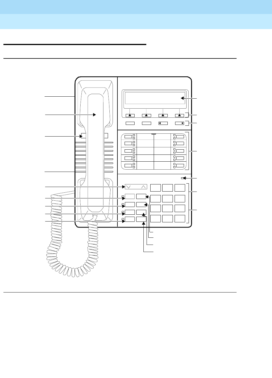
DEFINITYEnterpriseCommunicationsServerandSystem75andSystem85
Terminals and Adjuncts Reference
555-015-201 Issue 11
December 1999
ISDN Voice Terminals
17-29The ISDN 8510 Voice/Data Terminal
17
The ISDN 8510 Voice/Data Terminal
Figure 17-5. The ISDN 8510T Voice/Data Terminal
123
456
789
ABC DEF
MNOJKLGHI
PQRS TUV WXYZ
*
O#
Oper
ISDN 8510T
Dial Pad
Handset
Hold Button
Redial Button
Exit Button
Drop Button
Volume
Volume
Mute Redial
Speaker Exit
Conf Drop
Transfer Hold
a
b
c
Display
10 Call
Appearance/
Message Light
Mute Button
Speaker Button
Conference
Transfer
Telephone
4 Softkeys
NextPrevMenu Dir
d
e
f
g
h
i
j
4 Display
Feature
Adjunct Jack
Handset Jack
Desk Stand
(on bottom
of voice
Control
(on bottom of
voice terminal)
Number
Card
Control Button
terminal)
Buttons
Designation
Buttons and
Card
Button
Button

DEFINITYEnterpriseCommunicationsServerandSystem75andSystem85
Terminals and Adjuncts Reference
555-015-201 Issue 11
December 1999
ISDN Voice Terminals
17-30The ISDN 8510 Voice/Data Terminal
17
The 8510T voice/data terminal is used with the Integrated Services Digital
Network (ISDN) communication system through a 4-wire “T”-interface. The 8510T
voice/data terminal offers the following: 10 call appearance/feature buttons, each
with a red and green status light, buttons for the Mute, Redial, Conference, Drop,
Transfer, and Hold features (the MUTE, SPEAKER, CONF, and TRANSFER
buttons have a red light next to them), a Speakerphone which can also be
optioned as a listen-only Speaker, a Volume control, the K-type handset which
offers improved acoustic quality, an Adjunct jack for adjunct equipment, and
touch-tone dialing. Four softkeys (the keys with arrows printed on them) and four
display control buttons located below a 2-line by 24-character liquid crystal display
can be used to access such features as a personal Directory, a Call Log which
lists the most recent incoming and outgoing calls, the Self-Test feature, and a
personalized ringing pattern for the terminal.
Applications
The 8510T voice/data terminal can be used with the DEFINITY Communications
System Generic 2 and Generic 3, and the DEFINITY ECS. It can be used as a
voice terminal, data terminal, or a video phone. For the last two applications, you
will need to install a special (data or video) board in the 8510T voice terminal.
Physical Description
Dimensions
NOTE:
The dimensions given here for the 8510T voice/data terminal are
approximate.
Width = 7-3/4 inches
Depth (front to back) = 9-1/2 inches
Height (maximum with handset in place)
The desk-mounted model = 5-1/4 inches
The wall-mounted model = 4-1/2 inches

DEFINITYEnterpriseCommunicationsServerandSystem75andSystem85
Terminals and Adjuncts Reference
555-015-201 Issue 11
December 1999
ISDN Voice Terminals
17-31The ISDN 8510 Voice/Data Terminal
17
Features
Nine Fixed Features
■CONF button
■DROP button
■TRANSFER button
■HOLD button
■MUTE button
■SPEAKER button
■EXIT button
■REDIAL button
■VOLUME control button
Message Light
The red Message light goes on when a message is left for the user. This light
goes off when the user retrieves the message.
Call Appearance/Feature buttons
These 10 buttons are devoted
either
to handling incoming and outgoing calls (call
appearances) and are labeled with the exchange (numbers) and extension
number
or
they can be used as feature buttons to access voice features such as
Call Forward or Send All Calls; these are labeled with the feature name. Each of
these 10 call appearance/feature buttons has a red light, which indicates the
selected line and a green light which indicates the status of that line or feature.
REDIAL button
With the Redial feature, the user can redial the telephone number last dialed from
the dial pad. (The handset must be off-hook, or the speaker must be active.) Up to
37 digits can be redialed.
Speakerphone (Listen and Speak) Feature
The 8510T voice/data terminal is equipped with a built-in S201A-type
speakerphone. The Speakerphone capability allows a user to engage in a
hands-free 2-way conversation with the far-end party. The speakerphone can be
turned off or on with the SPEAKER button; it can be muted with the MUTE button,
and the volume can be controlled with the VOLUME “arrow” button.
With the softkeys, the user can adjust the speakerphone for optimal performance.
The user hears a set of tones as the speakerphone performs an acoustic test of
the environment. When the tones stop, the speakerphone has finished adjusting
itself and is ready for use. The user should reset the speakerphone whenever the
voice terminal (or the table or desk on which the terminal is situated) is moved to
another place (even in the same room).

DEFINITYEnterpriseCommunicationsServerandSystem75andSystem85
Terminals and Adjuncts Reference
555-015-201 Issue 11
December 1999
ISDN Voice Terminals
17-32The ISDN 8510 Voice/Data Terminal
17
Speaker (Listen-only) Feature
The 8510T voice/data terminal can be optioned for the Speakerphone (listen and
speak)
or
the Speaker (listen-only) feature. (The voice terminal is shipped with the
Speakerphone setting in place.)
The Speaker (listen-only) capability allows a user to engage in a one-way
conversation with the far-end. The user can only listen to the far-end; the user is
not able to transmit his voice over the speaker. Use the SPEAKER button on the
front of the voice terminal for turning on and off the speaker or speakerphone. To
speak with the far-end, the user must use the handset. Lifting the handset turns
off the speaker.
MUTE button
While on a call, the user can press the MUTE button (the red light next to the
button goes on), so the user can converse with someone in the same room
without the other party hearing the conversation. The user is placed in listen-only
mode. To disable the feature, the user presses the MUTE button a second time
(the red light goes off). The Mute function works only with the handset or with the
built-in speakerphone.
EXIT button
The EXIT button is used for exiting a softkey feature and returning to Normal
call-handling Mode.
VOLUME control button
When the user is on a call using the speakerphone, the VOLUME “arrow” button
raises or lowers the volume on the speakerphone Likewise, when the user is on a
call using the handset, the VOLUME control changes the receive level of the
handset. When the handset is on-hook and the speakerphone is off, this button
raises or lowers the ringer volume and tones such as the confirmation and error
tone.
Softkeys
The four buttons located below the display and labeled with arrows ( ),
correspond to words on the display screen. Softkeys are used along with display
control keys to access the following features:
■Setting the clock
■Setting the speakerphone
■Adding, editing, and deleting the numbers and associated names in the
voice terminal Directory
■Viewing a Directory entry and then placing a call to the number currently
shown on the display screen
■Using to quickly place a call to a number located in your Directory
■Using the Call Log to view incoming and/or outgoing calls
Dir
DEFINITYEnterpriseCommunicationsServerandSystem75andSystem85
Terminals and Adjuncts Reference
555-015-201 Issue 11
December 1999
ISDN Voice Terminals
17-33The ISDN 8510 Voice/Data Terminal
17
■Choosing to display an indicator when new calls are logged
■Locking and unlocking the Directory, Call Log, and all softkey functions
■Changing or removing your password
■Initiating a self-test of the voice terminal’s lights, ringer, buttons, and dial
pad keys
■Selecting the contrast level for the display
■Selecting a personalized ringing pattern
■Setting the rate at which the display messages are shown on the screen
■Adding confirmation or error tones to display messages
■Setting the number of names on a Directory page
■On an 8510 voice/data terminal, setting data features (See “Data Features”
later in this section for more information on data features.)
Display control buttons
These four buttons are labeled ,, , and .
■is used to access the main softkey menu.
■allows you to quickly access Directory entries in order to place a
call.
■and can be used to help you go back and forth through
menu options, to add, edit, or search for an entry in your Directory, and to
view entries in your Call Log.
Other Physical Features
Handset
The 8510T is equipped with a K-type handset.
A K-type Noisy Environment Handset (PEC: 31052A) can also be purchased and
connected to the 8510T terminal.
Dial pad
The 8510T is equipped with a standard 12-button touch-tone dial pad for dialing
telephone numbers or accessing features. The letters “Q” and “Z” have been
added to the appropriate dial pad keys for directory access, and the “5” button on
your dial pad has raised bars for visually-impaired users.
Menu Dir Prev Next
Menu
Dir
Prev Next

DEFINITYEnterpriseCommunicationsServerandSystem75andSystem85
Terminals and Adjuncts Reference
555-015-201 Issue 11
December 1999
ISDN Voice Terminals
17-34The ISDN 8510 Voice/Data Terminal
17
Kickstand
The kickstand on the bottom of the terminal can be lifted from the desktop stand
or can be left level with the bottom of the terminal. The user should check which
kickstand adjustment allows the best viewing angle of the display.
NOTE:
When the kickstand is raised or lowered, the speakerphone should be
re-calibrated to compensate for the new position.
Ringing
The 8510T has electronic tone ringing with eight possible personalized ringing
patterns that can be selected through the softkeys and the display control buttons.
Ringer volume is controlled by the VOLUME “arrow” button when the terminal is
on-hook.
Jacks
The 8510T voice/data terminal housing contains three jacks. The Handset cord
jack, for connecting the handset to the terminal, is located on the bottom of the
housing, near the front of the terminal. The Line jack, for connecting the line cord
to the terminal, is located on the bottom (left center) of the terminal. The Adjunct
jack, which is located on the bottom of the voice terminal directly below the Line
jack, is used for connecting optional adjunct equipment such as an S201A
Speakerphone or a 500A Headset Adapter to the terminal.
NOTE:
When an ADB (board) is installed in the 8510T terminal for data operations,
the RS232 jack is visible on the rear of the set for connecting data
equipment. When a TMI board is installed in the 8510T, two jacks are visible
on the rear of the set: the RS232 for the data connection and an 8-pin round
connector for connection of a video cable.
Cords
Two cords are supplied with the 8510T: a coiled 9-foot modular Handset cord and
a 7-foot Line cord. An optional 12-foot Handset cord is available.
ADB and TMI Boards
An Asynchronous Data Board (ADB) can be installed in the 8510T for data
applications. A TMI (Telephone Multimedia Interface) board can be installed if the
8510T is to be used as a video terminal.
Mounting Options
The 8510T comes equipped with a desk stand. However, the desk stand can be
removed, and the terminal can be mounted on the wall. If you choose to
wall-mount the voice terminal, use the instructions included in the 8510T Voice
Terminal Wall Mounting Kit (Comcode: 106614894).

DEFINITYEnterpriseCommunicationsServerandSystem75andSystem85
Terminals and Adjuncts Reference
555-015-201 Issue 11
December 1999
ISDN Voice Terminals
17-35The ISDN 8510 Voice/Data Terminal
17
Color Options
The 8510T is available in black or in white.
Data Features
■Asynchronous full-duplex operation at data rates from 1200 bits per second
(bps) to 57.6 kilobits per second (kbps) through an EIA-232 interface.
■X.25 packet switched data communication including receipt of X.29
commands from a remote X.25 host for setting packet switched data
parameters.
■Circuit switched data communication over 56 or 64 kbps facilities via
industry standard V.120 rate adaption protocol.
■Circuit switched data communication over 64 kbps facilities via Lucent
Technologies’ Digital Multiplexed Interface (DMI) Mode 2 or Mode 3 rate
adaption protocols.
■API allows a PC to control all aspects of the set’s interaction with the user
and with the network.
■The four softkeys and four display control buttons located below the liquid
crystal display can be used to access data features such as view current
options, change options, answer a data call, place a data call, reset a
locked data set, and selecting to display a data indicator.
■A user friendly command interface with on-screen help, nine programmable
named data memory numbers, and four programmable data option profiles.
■An expanded Hayes AT command set interface for compatibility with
applications which require this command format.
■Remote and local loopback tests.
For more information about the data features on an 8500-Series terminal, see the
ISDN 8500 Series Display Terminal ADM User’s Manual
, 555-021-730.
Distance Limitations
For the DEFINITY G2 and G3 and DEFINITY ECS, in which multipoint
configuration is used, the maximum signaling distance possible from the port
board to the work location
jack is:
NOTE:
The terminating resistor should be within 250 feet of the work location; the
distances listed are applicable for up to two voice/data terminals.
■If 24 AWG cable is used = 1600 feet
■If 26 AWG cable is used = 1330 feet

DEFINITYEnterpriseCommunicationsServerandSystem75andSystem85
Terminals and Adjuncts Reference
555-015-201 Issue 11
December 1999
ISDN Voice Terminals
17-36The ISDN 8510 Voice/Data Terminal
17
Power Requirements
Phantom or Auxiliary Power
The 8510T can receive power from the switch or from an auxiliary power supply.
NOTE:
A voice/data set should be auxiliary powered only.
The installer can select the type of power used by placing the two power jumpers
over the correct set of pins.
The power option jumpers are located at the bottom center of the terminal. On the
right side of the pins, on the plastic housing, you will see the label POWER and a
diagram of the correct settings. The jumpers are labeled PHAN (phantom power)
and AUX (auxiliary power). The terminal is shipped in the AUX position. You must
verify that the jumper settings are set correctly for your configuration.
NOTE:
The power jumpers must be set
only
by qualified service personnel.
■PHAN (phantom power) should be selected when power is provided by the
PBX. When the jumpers are set to PHAN, in idle condition, less than one
Watt of power will be drawn from the switch. The power option resistors are
set to PHAN if each of the two jumpers covers the two top pins in each set.
(The bottom pin in each set is left uncovered.)
■AUX (auxiliary power) should be selected when power is provided in the
closet. When the jumpers are set to AUX, the 8510T will operate on a
nominal 40 or 48 Vdc, UL-listed Communications Circuit Power source.
The power option resistors are set to AUX if each of the two jumpers covers
the two lower pins in each set. (The top pin in each set is left uncovered.)
NOTE:
It is a requirement that 8510T voice only terminals in a multipoint
configuration (two or more terminals per port) be auxiliary powered. If
used ONLY in a point-to-point configuration (one terminal per port),
8510T terminals may be phantom powered. When used in a mixed
point-to-point and multipoint configuration, all 8510T terminals MUST
be auxiliary powered.
If a phantom powered 8510T is moved from an existing point-to-point
to a multipoint configuration, the power jumper must be changed from
PHAN to AUX, and the terminal connected to an auxiliary power
source. The terminal will still work in the PHAN mode, but the power
jumper must still be changed. Exceeding the phantom power capacity
will trip the breaker in the carrier, causing a loss of service.

DEFINITYEnterpriseCommunicationsServerandSystem75andSystem85
Terminals and Adjuncts Reference
555-015-201 Issue 11
December 1999
ISDN Voice Terminals
17-37The ISDN 8510 Voice/Data Terminal
17
Recommended power supplies are the 1151A1 and 1151A2 with
Battery Holdover, and MSP-1 (local) Power Supplies and the 1145A
and 1145B1 Bulk Power Supplies.
Terminating Resistors
The terminating resistor jumpers are located on the upper left side on the bottom
of the terminal. Above the pins, on the plastic housing, you will see the label
TERM RESISTOR and a diagram of the correct settings.
These jumpers enable (ON) or bypass (OFF) the terminating resistor. The set is
shipped with the jumpers in the OFF position bypassing the terminating resistor.
You must verify that the jumper settings are set correctly for your configuration.
NOTE:
The terminating resistor jumpers must be set
only
by qualified service
personnel.
■The terminating resistor jumpers must be set to OFF when the set is in a
point-to-point configuration and the terminating resistor is in the closet or a
440A4 is connected on the line. When set to OFF, each of the two
terminating resistor jumpers covers the two top pins in each set. (The
bottom pin in each set is left uncovered.)
■The terminating resistor jumpers must be set to ON when the set is in a
point-to-point configuration and the terminating resistor is
not
in the closet
or a 440A4 is
not
connected to the line. When set to ON, each of the two
terminating resistor jumpers covers the two lower pins in each set. (The top
pin in each set is left uncovered.)
■The terminating resistor jumpers must be set to OFF when the set is in a
multipoint configuration and the terminating resistor is in the closet, a
440A4 is connected on the line, or the jumper is set to ON in one of the
other sets on the line. When set to OFF, each of the two terminating
resistor jumpers covers the two top pins in each set. (The bottom pin in
each set is left uncovered.)
■The terminating resistor jumpers must be set to ON when the set is in a
multipoint configuration and the terminating resistor is
not
in the closet, a
440A4 is not connected on the line, or the jumper is not set to ON in any of
the other sets on the line. When set to ON, each of the two terminating
resistor jumpers covers the two lower pins in each set. (The top pin in each
set is left uncovered.)
Switch Administration
Use the following information for administering an ISDN 8510T voice terminal.
■An 8510T voice terminal connected to a DEFINITY G2 should be aliased
as a 7507 voice terminal.

DEFINITYEnterpriseCommunicationsServerandSystem75andSystem85
Terminals and Adjuncts Reference
555-015-201 Issue 11
December 1999
ISDN Voice Terminals
17-38The ISDN 8510 Voice/Data Terminal
17
■An 8510T voice terminal connected to a DEFINITY G3 or a DEFINITY ECS
canbeadministeredasitself.
■An 8510T data terminal connected to a DEFINITY G2 or G3 or to a
DEFINITY ECS should be aliased as a 7507 with data.
Button Numbering
The following information can be used to administer the ISDN 8510T voice
terminal.
■When the terminal is connected to a DEFINITY G3 or to a DEFINITY ECS,
the 10 call appearance/feature buttons should be administered as
“BUTTON ASSIGNMENTS” 1 through 10. The Normal feature (the Exit
button) should be administered on Button #11.
■When the terminal is connected to a DEFINITY G2, the 10 call
appearance/feature buttons should be administered as “BUTTON
ASSIGNMENTS” 3 through 12. The Normal feature (the Exit button) should
be administered on Button #13.
The Service Profiler ID (SPID)
When ISDN terminals are initially installed, a unique SPID number must be
entered into the terminal. This number identifies the terminal to the network.
Usually, the system manager provides the SPID for each terminal in the system.
Use the following procedure for entering the SPID in an ISDN 8510T terminal.
1. Press and then press .
2. Dial the numbers, “43” (ID).
3. Press on the dial pad.
4. Enter digits from the dial pad for a new SPID number. If, at any point, you
make a mistake, press to erase the number and re-enter the SPID.
5. When the SPID number is correct, press on the dial pad to save the
new SPID in the terminal.
Hidden/Craft Features
The
ISDN Terminals Installation and Tests Manual
, Issue 3, 555-021-101,
contains information on completing the following tasks for the ISDN 8510T
voice/data terminal:
■How to enable or disable the listen-only speaker or the speakerphone
■How to enable Selectable Ring Preference
■How to clear all parameters stored in memory
■How to clear a user’s password
Menu Mute
*
#
*

DEFINITYEnterpriseCommunicationsServerandSystem75andSystem85
Terminals and Adjuncts Reference
555-015-201 Issue 11
December 1999
ISDN Voice Terminals
17-39The ISDN 8510 Voice/Data Terminal
17
■How to set a password known only by the system manager
■How to send or disable Button Number 11
Power Failure Operation
The 8510T cannot be used as an emergency station during power failure transfer
conditions.
FCC Registration
The 8510T voice/data terminal is FCC registered as a Class A terminal.
Hearing Aid Compatible
This terminal is compatible with the inductively coupled hearing aids as required
by the FCC.
8510T Equipment PECs and Comcodes
The 8510T voice/data terminal and optional components can be ordered with the
following PECs and Comcodes:
■ISDN 8510T Voice Terminal
PEC: 3117-001 (Black=COL09; White=COL10)
Comcode: Black=106604382; White=106604390
■ISDN 8510T Data Terminal
PEC: 3117-002 (Black=COL09; White=COL10)
Comcode: Black=106604424; White=106604432
■ISDN 8510T TMI Terminal
Comcode: Black=106899982; White=106899990
■Handset
PEC: 31149 (Black=COL09; White=COL10)
Comcode: Black=106050065; White=106053408
■Handset for Noisy Environments
PEC: 31052A (Black=COL09; White=COL10)
■Handset cord (9 feet)
Comcode: Black=105635429; White=105701809
■Handset cord (12 feet)
PEC: 2725-01L (Black=COL09; White=COL10)
Comcode: Black=102401445; White=104211339
■Line cord (7 feet)
PEC: 2725-07G
Comcode: 103786778

DEFINITYEnterpriseCommunicationsServerandSystem75andSystem85
Terminals and Adjuncts Reference
555-015-201 Issue 11
December 1999
ISDN Voice Terminals
17-40The ISDN 8510 Voice/Data Terminal
17
■Designation card
PEC: 31170
Comcode: 847065467 (package of six 8 1/2'' by 11'' cards, 67 sheets)
846819530 (package of tractor feed 9 8'' by 17'' cards, 34 sheets, to be
used with LabelMaster)
■8510 Data Upgrade Kit
PEC: 32254A
Comcode: 106811979
Adjuncts
The following adjuncts can be used with the 8510T voice/data terminal:
■500A Headset Adapter (and a standard headset; see “Headsets” below)
■S101A Speakerphone (no longer orderable)
■S201A Speakerphone
Headsets
A list of compatible headsets, consisting of both modular and plug prong base
units and selection of headpieces, appears in “Headset Adapters” in the Adjuncts
section later in this manual.
Additional Documents
The following documents contain additional information relating to the 8510T
voice/data terminal: (Use the 9-digit number listed after each document to order
that book from the BCS Publications Center for Lucent Technologies.)
■
ISDN 8510T Voice Terminal User’s Manual
, 555-021-736
■
ISDN 8510T Voice Terminal Quick Reference Guide
, 555-021-735
■
ISDN 8510T Voice Terminal Instructions for Changing the Jumper Settings
for the Terminating Resistors and for AUX and PHAN Power Options
,
555-021-738
■
ISDN 8510T Voice Terminal Instructions for Installing the Asynchronous
Data Board (ADM) or Telephone Multimedia Interface (TMI) Board
,
555-021-754
■
DEFINITY Generic 3 ISDN 8510T Voice Terminal User’s Guide
,
555-230-748
■
ISDN 8500 Series Display Terminal ADM User’s Manual
, 555-021-730
■
Integrated Services Digital Network (ISDN) Terminals Installation and
Tes t s
, 555-021-101
■
ISDN Application Programming Interface (API) Programmer’s Reference
Manual
, 533-705-200
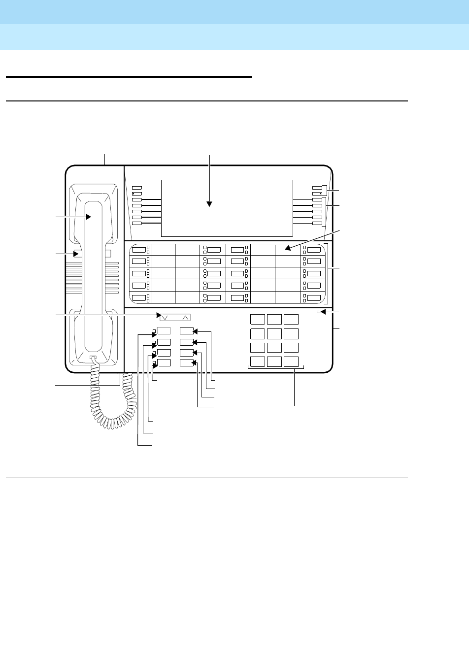
DEFINITYEnterpriseCommunicationsServerandSystem75andSystem85
Terminals and Adjuncts Reference
555-015-201 Issue 11
December 1999
ISDN Voice Terminals
17-41The ISDN 8520T Voice/Data Terminal
17
The ISDN 8520T Voice/Data Terminal
Figure 17-6. The ISDN 8520T Voice/Data Terminal
123
456
789
ABC DEF
MNOJKLGHI
PQRS TUV WXYZ
*
O#
Oper
Volume
Mute Redial
Speaker Exit
Conf Drop
Transfer Hold
a
b
c
d
e
f
g
h
i
j
ISDN 8520T
Dir
Next
Menu
Prev
k
l
m
n
o
p
q
r
s
t
Message
Adjunct Jack
RS232 Connector
Dial Pad
Display
20 Call
Message Light
10 Softkeys
4Display
Designation
Control
Hold Button
Redial Button
Exit Button
Drop Button
(on bottom of
voice terminal)
Feature
Appearance/
Handset
Volume
Mute Button
Telephone
Number
Card
Button
Control
Speaker Button
Transfer
Buttons
Card
Handset
Jack Button
Conference Button
Buttons

DEFINITYEnterpriseCommunicationsServerandSystem75andSystem85
Terminals and Adjuncts Reference
555-015-201 Issue 11
December 1999
ISDN Voice Terminals
17-42The ISDN 8520T Voice/Data Terminal
17
The 8520T voice/data terminal is used with the ISDN communication system
through a 4-wire “T”-interface. The 8520T voice/data terminal offers the following:
20 call appearance/feature buttons, each with a red and green status light, buttons
for the Mute, Redial, Conference, Drop, Transfer, and Hold features (the MUTE,
SPEAKER, CONF, and TRANSFER buttons have a red light next to them), a
Speakerphone which can also be optioned as a listen-only Speaker, a Volume
control, improved acoustic quality with the K-type handset, an Adjunct jack for
adjunct equipment, and touch-tone dialing. Ten softkeys and four display control
buttons located on either side of the 7-line by 24-character liquid crystal display
can be used to access such features as a personal Directory, a Call Log which
lists the most recent incoming and outgoing calls, the Self-Test feature, and a
personalized ringing pattern for the voice/data terminal.
Applications
The 8520T voice/data terminal can be used with the DEFINITY Communications
System Generic 2 and Generic 3, and the DEFINITY ECS. It can be used as a
voice terminal or a data terminal.
Physical Description
Dimensions
NOTE:
The dimensions given here for the 8520T voice/data terminal are
approximate.
Width = 11-1/2 inches
Depth (front to back) = 10-1/4 inches
Height (maximum with handset in place) = 5-3/8 inches

DEFINITYEnterpriseCommunicationsServerandSystem75andSystem85
Terminals and Adjuncts Reference
555-015-201 Issue 11
December 1999
ISDN Voice Terminals
17-43The ISDN 8520T Voice/Data Terminal
17
Features
Nine Fixed Features
■CONF button
■DROP button
■TRANSFER button
■HOLD button
■MUTE button
■SPEAKER button
■EXIT button
■REDIAL button
■VOLUME button
Message Light
The red Message light goes on when a message is left for the user. This light
goes off when the user retrieves the message.
Call Appearance/Feature buttons
These 20 buttons are devoted
either
to handling incoming and outgoing calls (call
appearances) and are labeled with the exchange (numbers) and extension
number
or
they can be used as feature buttons to access voice features such as
Call Forward or Send All Calls; these are labeled with the feature name. Each of
these 20 call appearance/feature buttons has a red light, which indicates the
selected line, and a green light which indicates the status of that line or feature.
REDIAL button
With the Redial feature, the user can redial the telephone number last dialed from
the dial pad. (The handset must be off-hook, or the speaker must be active.) Up to
37 digits can be redialed.
Speakerphone (Listen and Speak) Feature
The 8520T voice/data terminal is equipped with a built-in S201A-type
speakerphone. The Speakerphone capability allows a user to engage in a
hands-free 2-way conversation with the far-end party. The speakerphone can be
turned off or on with the SPEAKER button; it can be muted with the MUTE button,
and the volume can be controlled with the VOLUME “arrow” button.
With the softkeys, the user can adjust the speakerphone for optimal performance.
The user hears a set of tones as the speakerphone performs an acoustic test of
the environment. When the tones stop, the speakerphone has finished adjusting
itself and is ready for use. The user should reset the speakerphone whenever the
voice/data terminal (or the table or desk on which the terminal is situated) is
moved to another place (even in the same room).

DEFINITYEnterpriseCommunicationsServerandSystem75andSystem85
Terminals and Adjuncts Reference
555-015-201 Issue 11
December 1999
ISDN Voice Terminals
17-44The ISDN 8520T Voice/Data Terminal
17
Speaker (Listen-only) Feature
The 8520T voice/data terminal can be optioned for the Speakerphone (listen and
speak)
or
the Speaker (listen-only) feature. (The terminal is shipped with the
Speakerphone setting in place.)
The Speaker (listen-only) capability allows a user to engage in a one-way
conversation with the far-end. The user can only listen to the far-end; the user is
not able to transmit his voice over the speaker. Use the SPEAKER button on the
front of the terminal for turning on and off the speaker or speakerphone. To speak
with the far-end, the user must use the handset. Lifting the handset turns off the
speaker.
MUTE button
While on a call, the user can press the MUTE button (the red light next to the
button goes on), so the user can converse with someone in the same room
without the other party hearing the conversation. The user is placed in listen-only
mode. To disable the feature, the user presses the MUTE button a second time
(the red light goes off). The Mute function works only with the speakerphone and
the handset.
EXIT button
The EXIT button is used for exiting a softkey feature and returning to the
user-selected Home Screen. The top two lines again show you the time and date
and any relevant system information.
VOLUME control button
When the user is on a call using the speakerphone, the VOLUME “arrow” button
raises or lowers the volume on the speakerphone. Likewise, when the user is on a
call using the handset, the VOLUME control button changes the receive level of
the handset. When the handset is on-hook and the speakerphone is off, this
button raises or lowers the ringer volume or tones such as the confirmation or
error tone.
Softkeys
The 10 unlabeled buttons located on both sides of the display correspond to
words on the display screen. Softkeys are used along with display control keys to
access the following features:
■Setting the clock
■Setting the speakerphone
■Adding, editing, and deleting the numbers and associated names (and
optional group names) in the voice terminal Directory
■Organizing your Directory in alphabetical order or by group name,
renaming a group, and moving Directory entries from one group into
another
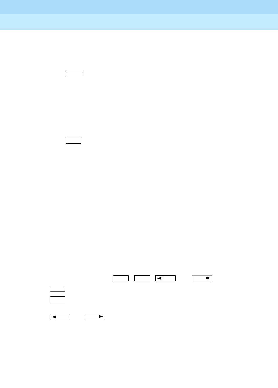
DEFINITYEnterpriseCommunicationsServerandSystem75andSystem85
Terminals and Adjuncts Reference
555-015-201 Issue 11
December 1999
ISDN Voice Terminals
17-45The ISDN 8520T Voice/Data Terminal
17
■Searching the Directory for a particular entry, by name or by number, and
then placing a call to the number currently shown on the display screen
■Viewing the contents of your Directory, and then editing, deleting, or
placing a call to the number currently shown on the display screen
■Using to quickly place a call to a number located in your Directory
■Using the Call Log to view incoming and/or outgoing calls
■Choosing to display an indicator when new calls are logged
■Locking and unlocking any Directory Changes, the Call Log, and all Softkey
functions
■Changing or removing your password
■Selecting a home screen, which your display will return to whenever you
press
■Initiating a self-test of the voice/data terminal’s lights, ringer, buttons, and
display
■Selecting the contrast level for the display
■Selecting a personalized ringing pattern
■Selecting the type of display messages shown on the display screen (all
messages or only error messages) and setting the rate at which the display
messages are shown
■Adding confirmation or error tones to display messages
■Setting the number of names on a Directory page
■Providing Service Information if the terminal is used for data functions
■Choosing if and when the speaker becomes active while placing a voice
call using your PC
Display control buttons
These four buttons are labeled ,, , and .
■is used to access the main softkey menu.
■allows you to quickly access Directory entries in order to place a
call.
■and can be used to help you go back and forth through
menu options, to add, edit, or search for an entry in your Directory, and to
view entries in your Call Log.
Dir
Exit
Menu Dir Prev Next
Menu
Dir
Prev Next

DEFINITYEnterpriseCommunicationsServerandSystem75andSystem85
Terminals and Adjuncts Reference
555-015-201 Issue 11
December 1999
ISDN Voice Terminals
17-46The ISDN 8520T Voice/Data Terminal
17
Other Physical Features
Handset
The 8520T voice/data terminal is equipped with a K-type handset.
A K-type Noisy Environment Handset (PEC: 31052A) can also be purchased and
connected to the 8520T terminal.
Dial pad
The 8520T is equipped with a standard 12-button touch-tone dial pad for dialing
telephone numbers or accessing features. The letters “Q” and “Z” have been
added to the appropriate dial pad keys for directory access, and the “5” button on
your dial pad has raised bars for visually-impaired users.
Ringing
The 8520T has electronic tone ringing with eight possible personalized ringing
patterns that can be selected through the softkeys and the display control buttons.
Ringer volume is controlled by the VOLUME “arrow” button when the terminal is
on-hook.
Jacks
The 8520T housing contains three jacks. The Handset cord jack, for connecting
the handset to the voice/data terminal, is located on the bottom of the housing,
near the front of the terminal. The Line jack, for connecting the line cord to the
8520T, is located on the bottom (left center) of the set. The Adjunct jack, which is
located on the bottom of the set directly below the Line jack, is used for
connecting optional adjunct equipment such as an S201A Speakerphone or a
500A Headset Adapter to the voice/data terminal.
The RS232 jack on the rear of the set can be used for connecting data equipment.
Cords
Two cords are supplied with the 8520T voice/data terminal: a coiled 9-foot
modular Handset cord and a 7-foot Line cord. An optional 12-foot Handset cord is
available.
Mounting Options
The 8520T comes equipped with a desk stand. This voice/data terminal cannot be
wall-mounted.
Color Options
The 8520T is available in black or white.

DEFINITYEnterpriseCommunicationsServerandSystem75andSystem85
Terminals and Adjuncts Reference
555-015-201 Issue 11
December 1999
ISDN Voice Terminals
17-47The ISDN 8520T Voice/Data Terminal
17
Data Features
The ISDN 8520T voice terminal has the following data features:
■Asynchronous full-duplex operation at data rates from 1200 bits per second
(bps) to 57.6 kilobits per second (kbps) through an EIA-232 interface.
■X.25 packet switched data communication including receipt of X.29
commands from a remote X.25 host for setting packet switched data
parameters.
■Circuit switched data communication over 56 or 64 kbps facilities via
industry standard V.120 rate adaption protocol.
■Circuit switched data communication over 64 kbps facilities via Lucent
Technologies’ Digital Multiplexed Interface Mode 2 or Mode 3 rate adaption
protocols.
■API allows a PC to control all aspects of the set’s interaction with the user
and with the network.
■The 10 softkeys and four display control buttons located to the left and right
of the liquid crystal display can be used to access data features such as
view current options, change options, answer a data call, place a data call,
reset a locked data set, and selecting to display a data indicator. Note, the
first two lines of the 7-line display contain switch information; the remaining
five lines contain softkey information.
■A user-friendly command interface with on-screen help, nine
programmable named data memory numbers, and four programmable data
option profiles.
■An expanded Hayes AT command set interface for compatibility with
applications which require this command format.
■Remote and local loopback tests.
For more information about the data features on an 8500-Series terminal, see the
ISDN 8500 Series Display Terminal ADM User’s Manual
, 555-021-730.
Distance Limitations
For the DEFINITY G2 and G3 and the DEFINITY ECS, in which multipoint
configuration is used, the maximum signaling distance possible from the port
board to the work location jack is: (The terminating resistor should be within 250
feet of the work location; the distances listed are applicable for up to two
voice/data terminals.)
■If 24 AWG cable is used = 1600 feet
■If 26 AWG cable is used = 1330 feet

DEFINITYEnterpriseCommunicationsServerandSystem75andSystem85
Terminals and Adjuncts Reference
555-015-201 Issue 11
December 1999
ISDN Voice Terminals
17-48The ISDN 8520T Voice/Data Terminal
17
Power Requirements
Auxiliary Power Supply
The 8520T needs auxiliary power from an auxiliary power supply. Recommended
power supplies are the 1151A1 and 1151A2 with Battery Holdover and MSP-1
(local) Power Supplies and the 1145A and 1145B1 Bulk Power Supplies.
Terminating Resistor
The terminating resistor setting must be set by either a service representative or
the system administrator.
■The terminating resistor setting should be set to OUT when the voice/data
terminal is in a point-to-point configuration and the terminating resistor is in
the closet.
■The terminating resistor setting on the terminal should be set to IN when
the voice/data terminal is in a point-to-point configuration and the
terminating resistor is
not
in the closet.
■When terminals are part of a multipoint configuration and the terminating
resistor is in the closet, all sets should be set to OUT.
■When the terminating resistor is
not
in the closet and the terminals are part
of a multipoint configuration, only one of the sets in this configuration needs
to be set to IN. All the rest of the sets in this configuration should be set to
OUT.
To change the terminating resistor setting, do the following:
1. Press and then .
2. Dial the numbers “87” (TR).
3. The display screen shows you the current terminating resistor setting (IN or
OUT). Use the softkeys to toggle between the two settings, whichever is
correct for that terminal.
4. When the correct setting is shown on the display screen, press the softkey
beside Done.
Switch Administration
An 8520T voice/data terminal connected to a DEFINITY G2, G3i, G3r, or to a
DEFINITY ECS, should be aliased as a 7507 with data.
Menu Mute
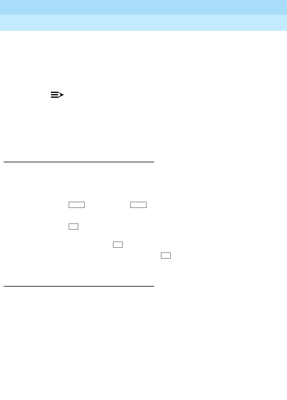
DEFINITYEnterpriseCommunicationsServerandSystem75andSystem85
Terminals and Adjuncts Reference
555-015-201 Issue 11
December 1999
ISDN Voice Terminals
17-49The ISDN 8520T Voice/Data Terminal
17
Button Numbering
The ISDN 8520T voice terminal must be administered in the following ways:
■When the terminal is connected to a DEFINITY G3 or a DEFINITY ECS,
the 20 call appearance/feature buttons should be administered as
“BUTTON ASSIGNMENTS” 1 through 20.
NOTE:
On a DEFINITY G3 or a DEFINITY ECS, the Normal or Exit feature
should be administered on Button #21.
■When the terminal is connected to a DEFINITY G2, the call
appearance/feature buttons should be administered as “BUTTON
ASSIGNMENTS” 3 through 22.
The Service Profiler ID (SPID)
When ISDN terminals are initially installed, a unique SPID number must be
entered into the terminal. This number identifies the terminal to the network.
Usually, the system manager provides the SPID for each terminal in the system.
Use the following procedure for entering the SPID in an ISDN 8520T terminal.
1. Press and then press .
2. Dial the numbers, “43” (ID).
3. Press on the dial pad.
4. Enter digits from the dial pad for a new SPID number. If, at any point, you
make a mistake, press to erase the number and re-enter the SPID.
5. When the SPID number is correct, press on the dial pad to save the
new SPID in the terminal.
Hidden/Craft Features
For information on the hidden or craft features, those features that can be done
only by qualified service personnel, use the procedures listed for the 8510T
terminal in the
ISDN Terminals Installation and Tests Manual
, Issue 3,
555-021-101. The section titled ISDN 8500-Series T-Interface Terminals in that
manual contains information on completing the following tasks for the ISDN
8510T voice/data terminal (the procedures for these tasks can also be used for
the 8520T):
■How to enable or disable the listen-only speaker or the speakerphone
■How to enable Selectable Ring Preference
■How to clear all parameters stored in memory
■How to clear a user’s password
Menu Mute
*
*
#

DEFINITYEnterpriseCommunicationsServerandSystem75andSystem85
Terminals and Adjuncts Reference
555-015-201 Issue 11
December 1999
ISDN Voice Terminals
17-50The ISDN 8520T Voice/Data Terminal
17
■How to clear a password known by the system administrator
■How to send or disable Button Number 11
Power Failure Operation
The 8520T cannot be used as an emergency station during power failure transfer
conditions.
FCC Registration
The 8520T voice/data terminal is FCC registered as a Class A terminal.
Hearing Aid Compatible
This voice/data terminal is compatible with the inductively coupled hearing aids as
required by the FCC.
8520T Equipment PECs and Comcodes
The 8520T voice/data terminal and optional components can be ordered with the
following PECs and Comcodes:
■ISDN 8520T Voice Terminal
PEC: 3116-001 (Black=COL09; White=COL10)
Comcode: Black=106906431; White=106906449
■Handset
PEC: 31149 (Black=COL09; White=COL10)
Comcode: Black=106050065; White=106053408
■Handset for Noisy Environments
PEC: 31052A (Black=COL09; White=COL10)
■Handset cord (9 feet)
Comcode: Black=105635429; White=105701809
■Handset cord (12 feet)
PEC: 2725-01L (Black=COL09; White=COL10)
Comcode: Black=102401445; White=104211339
■Line cord (7 feet)
PEC: 2725-07G
Comcode: 103786778
■Designation cards
6 sheets (each sheet has enough designation cards for 6 sets)
Comcode: 847244274
18 sheets (each sheet has enough designation cards for 6 sets)

DEFINITYEnterpriseCommunicationsServerandSystem75andSystem85
Terminals and Adjuncts Reference
555-015-201 Issue 11
December 1999
ISDN Voice Terminals
17-51The ISDN 8520T Voice/Data Terminal
17
Comcode: 847244282
68 sheets (each sheet has enough designation cards for 6 sets)
Comcode: 847244290
Adjuncts
The following adjuncts can be used with the 8520T terminal:
■500A Headset Adapter (and a standard headset; see “Headsets” below)
■S101A Speakerphone (no longer orderable)
■S201A Speakerphone
Headsets
A list of compatible headsets, consisting of both modular and plug prong base
units and selection of headpieces, appears in “Headset Adapters” in the Adjuncts
section later in this manual.
Additional Documents
The following documents contain additional information relating to the 8520T
voice/data terminal: (Use the 9-digit number listed after each document to order
that book from the BCS Publications Center for Lucent Technologies.)
■
ISDN 8520T Voice Terminal User’s Manual
, 555-021-758
■
DEFINITY Generic 3 ISDN 8520T Voice Terminal User’s Guide
,
555-230-767
■
ISDN 8500 Series Display Terminal ADM User’s Manual
, 555-021-730
■
ISDN Application Programming Interface (API) Programmer’s Reference
Manual
, 533-705-200

DEFINITYEnterpriseCommunicationsServerandSystem75andSystem85
Terminals and Adjuncts Reference
555-015-201 Issue 11
December 1999
ISDN Voice Terminals
17-52The ISDN 8520T Voice/Data Terminal
17

Cordless and Wireless Telephones
18-1
18
DEFINITYEnterpriseCommunicationsServerandSystem75andSystem85
Terminals and Adjuncts Reference
555-015-201 Issue 11
December 1999
18
Cordless and Wireless Telephones
The following cordless and wireless telephones are described in this section:
■The MDC 9000 Cordless Telephone
■The MDW 9000 Wireless Telephone
■The MDW 9031DCP Wireless Pocket Phone, both the single-zone and the
dual-zone models
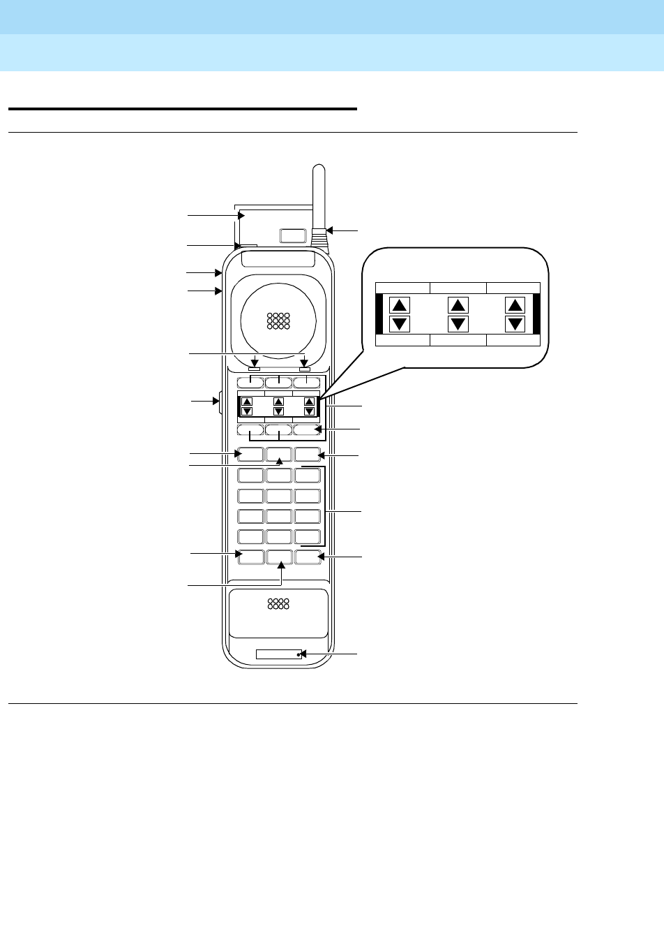
DEFINITYEnterpriseCommunicationsServerandSystem75andSystem85
Terminals and Adjuncts Reference
555-015-201 Issue 11
December 1999
Cordless and Wireless Telephones
18-2The MDC 9000 Cordless Telephone
18
The MDC 9000 Cordless Telephone
Figure 18-1. The MDC 9000 Telephone, Top View of Handset,
Including Enlarged Display Area
MDC 9000
Ext.
ON
RANGE
PSTAT
MSG
BATT
On/Off Hold
12 3
ABC DEF
4 5 6
JKL MNOGHI
7 8 9
TUV WXYZPQRS
*0#
Oper
ON
RANGE
PSTAT
MSG
BATT
Handset Display
User Instructions (pull-up) Antenna
5 Dual Purpose Outside Line/
Battery Charging Contacts
Earpiece Volume
Hold Button
Feat (Feature) Button
Trans (Transfer) Button
Conf (Conference) Button
Handset Extension Label
14
Stat
Stat (Status) Button
Headset Jack
Conf Trans Feat
To Update Display
Press Stat
Directory Card (behind)
On/Off Button
Headset On/Off Button
Drop
Drop Button
Dial Pad
Control Switch Programmable Buttons
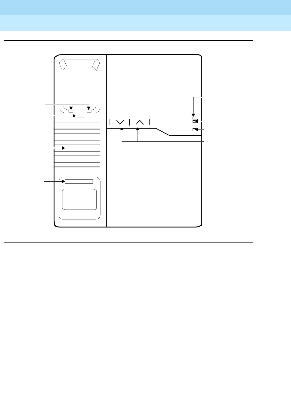
DEFINITYEnterpriseCommunicationsServerandSystem75andSystem85
Terminals and Adjuncts Reference
555-015-201 Issue 11
December 1999
Cordless and Wireless Telephones
18-3The MDC 9000 Cordless Telephone
18
Figure 18-2. The MDC 9000 Telephone, Top View of Charging Base
The MDC 9000 Cordless Telephone has two basic parts, the handset and the
charging base.
■The handset has line/programmable feature/intercom buttons, Conference,
Drop, Hold, Transfer, Status, and Feature buttons, Headset On/Off and
Handset On/Off buttons, a LCD display, an earpiece volume control switch,
battery charging contacts, a directory card, and a headset jack.
■The charging base has a handset hook, ringer volume controls, battery
charging contacts, a Talk indicator, a Charge indicator, a Message
indicator, and a base ringer.
In order to provide you with the freedom of mobility, the MDC 9000 is not
connected physically (by a line cord or wire from the handset) to the DEFINITY
Communications System Generic 1, Generic 2, or Generic 3, a DEFINITY
Enterprise Communications Server (ECS), System 75, or System 85. Instead, the
MDC 9000 handset communicates by way of a radio link to its radio base, which
connects to the telephone system.
Battery
Ext. 14
Tal k
Base
MDC 9000
Charge
Message
Ringer Volume
Base Ringer
Handset Hook
Talk Indicator
Charge Indicator
Message
Ringer
Charging
Contacts
Extension
Label
Indicator
Volume
Controls

DEFINITYEnterpriseCommunicationsServerandSystem75andSystem85
Terminals and Adjuncts Reference
555-015-201 Issue 11
December 1999
Cordless and Wireless Telephones
18-4The MDC 9000 Cordless Telephone
18
Applications
The MDC 9000 Cordless Telephone can be used with the DEFINITY
Communications System Generic 1, Generic 2, and Generic 3, the DEFINITY
ECS, System 75, and System 85.
Physical Features
Dimensions
NOTE:
The dimensions described here for the MDC 9000 handset and charging
base are approximate.
For the Handset:
Width = 2.44 inches
Length = 12.1 inches
Height = 2.3 inches
For the Charging Base:
Width = 7.52 inches
Length = 9.4 inches
Height = 3.43 inches
Handset Features
Fixed Feature Buttons
The MDC 9000 has the following eight fixed feature buttons:
■CONFERENCE button — labeled CONF
■DROP button — The DROP button is NOT labeled. It is located in the lower
right corner of the LCD display.
■TRANSFER button — labeled TRANS
■HOLD button
■FEATURE button — The Feature button (labeled FEAT) is not used.

DEFINITYEnterpriseCommunicationsServerandSystem75andSystem85
Terminals and Adjuncts Reference
555-015-201 Issue 11
December 1999
Cordless and Wireless Telephones
18-5The MDC 9000 Cordless Telephone
18
■STATUS button — The Status button (labeled STAT) is used to update all
handset visuals if pressed when the STAT indicator appears (the handset is
on), and to turn on the display when the handset is off.
■Headset On/Off button — This button is used for turning the headset on
and off.
■Handset (labeled ON/OFF) button — This button is used for turning the
handset on and off. (This button can also turn the headset on and off.)
Outside Line or Intercom/ Programmable Feature Buttons
When labeled with an extension number, these buttons indicate lines used for
incoming and outgoing calls (call appearances) and for using the telephone as an
intercom; when programmed and labeled with feature names, these buttons
access features (feature buttons). In use, the light next to that button is lit; when a
call is on hold, it winks.
LCD Display
The display provides information on line status, whether the telephone is out of
range, whether the battery is low, if you have a message, and when you are in
program mode.
Dial Pad
The telephone has a standard 12-button pad for dialing telephone numbers and
accessing features.
Directory Card
The set has a directory card for writing or typing names of frequently dialed
telephone numbers or extensions. It is located on the bottom of the handset cover.
User Instructions
The set also provides you with a quick reference that you can pull up to review
basic procedures for using this telephone’s features.
Antenna
The antenna is used for receiving the transmissions from the radio module. This
antenna is flexible and is permanently attached to the handset.
Earpiece Volume Control Switch
This volume control is used for sliding between the two earpiece volume control
positions, Normal and High.
Battery Charging Contacts
The contacts are used for charging the handset when contact is made with the
charging base.

DEFINITYEnterpriseCommunicationsServerandSystem75andSystem85
Terminals and Adjuncts Reference
555-015-201 Issue 11
December 1999
Cordless and Wireless Telephones
18-6The MDC 9000 Cordless Telephone
18
Headset Jack
This jack is used for connecting the headset to the handset.
Charging Base Features
Talk Indicator
This indicator is lit when the handset is off-hook. (The ON icon on the handset is
also lit.)
Charge Indicator
This indicator is lit when the battery is charging and the handset is properly placed
on the base.
Message Indicator
This indicator is lit when you have a message. (MSG also appears on the handset
display.)
Ringer Volume Controls
This volume control is used for adjusting the base’s ringing volume. Press the left
button to decrease the ringer volume; press the right button to increase the ringer
volume.
NOTE:
When the handset is on the base, only the base rings. Both ring when the
handset is out of the base.
Base Ringer
This is the ringer located in the base.
Handset Hook
This hook is used for hanging up the handset in the base.
Battery Charging Contacts
These charging contacts are used for charging the handset when contact is made
with the charging base.
Power Cord Jack
This jack is used for connecting the power cord to your telephone. This cord is
then plugged into a wall outlet. This jack is located on the other side of the base.

DEFINITYEnterpriseCommunicationsServerandSystem75andSystem85
Terminals and Adjuncts Reference
555-015-201 Issue 11
December 1999
Cordless and Wireless Telephones
18-7The MDC 9000 Cordless Telephone
18
Display Information
The telephone display provides visual call and telephone status information
through the following set of icons:
■or or shows the status of the adjacent button. If the triangle
and rectangle both appear, you are using that line; if only the rectangle
appears, the line is in use.
■ON appears when the handset is on.
■RANGE flashes to indicate that you are out of range and appears steadily
when you have lost communication.
■Pis
not
used with a DEFINITY switch or System 75 or System 85.
■STAT appears when the status mode is active, refreshing the icons and
indicating that you should move closer to the base.
■MSG appears when there is a message waiting for you.
■BATT appears when the battery is low.
Out-of-Range Indication
While the set is still active, it gives an audible indication (double beep) and visual
indication (the RANGE icon appears on the LCD display) when the handset is
getting out of range.
Distance and Installation Limitations (for the
Charging Base)
The MDC 9000 uses radio transmissions to communicate. The range depends on
your particular operating environment, and the range can be improved by placing
thebaseinanoptimumlocation.Thebasecanbeplacedonadeskormounted
on a wall.
Before you install the phone, note the following considerations:
■Mount the base near the center of the area in which the handset will be
used, but at least 20 feet away from the phone system switch.
■Install the base within 6 feet of a properly grounded 3-prong electrical
outlet that is not controlled by an on/off switch.
■If your phone system uses an uninterruptible power supply, such as a
backup generator, be sure to connect the base for the cordless phone to
that power supply.
■The base should not share the same power line or be within 6 feet of
equipment with microprocessors such as answering machines, personal
computers, and fax machines, 900 MHz wireless LANS and other

DEFINITYEnterpriseCommunicationsServerandSystem75andSystem85
Terminals and Adjuncts Reference
555-015-201 Issue 11
December 1999
Cordless and Wireless Telephones
18-8The MDC 9000 Cordless Telephone
18
equipment, phone system control units, uninterruptible power supplies,
copier machines or electric motors and industrial machinery. A distance of
20 feet is advisable for minimum interference.
■The base should be located at least 3 feet from metal sources. These
include metal reinforced ceilings, metal window frames, concrete reinforced
with metal, sheet metal walls, steel 1-beams, metal studs in walls, screens,
and fences.
■Some solid structures, such as moist concrete walls, brick walls, and steel
reinforced concrete walls, will inhibit the range.
■If more than one cordless phone is being used, do not place a handset
from one cordless phone into the base of another. If this accidentally
occurs, place each handset in the correct base for at least 10 seconds.
Switch Administration
Aliasing
For all System 75, System 85, DEFINITY Generic 1, and Generic 2 switches, and
DEFINITY Generic 3, Versions 1 and 2, the MDC 9000 terminal must be
administered as a 7303S Hybrid terminal.
Beginning with the DEFINITY Generic 3, Version 3 (or later), the MDC 9000 can
be administered as itself.
For the System 85, R2V1 through R2V4 switch which does not accommodate
Universal modules, an ANN17B Hybrid pack in conjunction with a DS-1 carrier
must be used to connect the switch and the MDC 9000 terminal. On all other
switches, including System 75, DEFINITY Generic 1, Generic 2, and Generic 3,
and the DEFINITY ECS, a TN62B Hybrid pack must be used with the Universal
carrier for this purpose.
NOTE:
A DEFINITY Generic 2 may use either an ANN17B or a TN62B pack. In
either case, the latest vintage packs are recommended.
Button Numbering
Only the system manager should administer feature button assignments on the
telephone. It is recommended that you not use a feature that requires visuals (that
is, the light next to each administrable button) to be updated while the set is turned
off, or any feature that may be activated by button depression while the set is
turned off (for example, Send All Calls).
Use Figure 18-3 for button numbering on the MDC 9000 set when it is connected
to a System 75, a DEFINITY Generic 1 or Generic 3, or to a DEFINITY ECS. Use
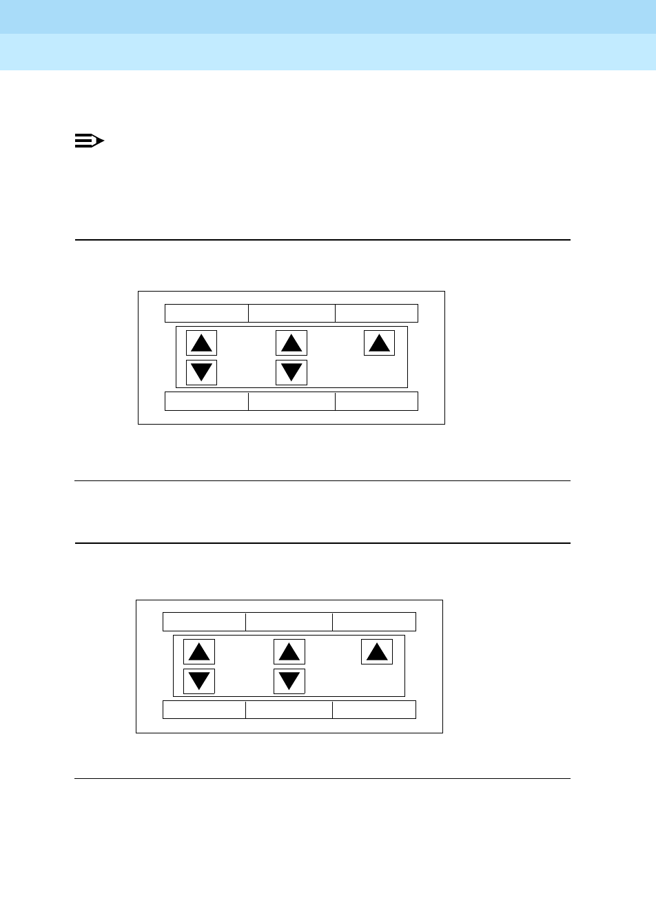
DEFINITYEnterpriseCommunicationsServerandSystem75andSystem85
Terminals and Adjuncts Reference
555-015-201 Issue 11
December 1999
Cordless and Wireless Telephones
18-9The MDC 9000 Cordless Telephone
18
Figure 18-4 for button numbering on the MDC 9000 set when it is connected to a
System 85 or a DEFINITY Generic 2.
NOTE:
On System 75, the DEFINITY Generic 1 and Generic 3, or a DEFINITY
ECS, button numbering begins with “1,” the button on the upper right of the
display. On System 85 and the DEFINITY Generic 2, button numbering
starts with “3.”
Figure 18-3. Button Numbering for a MDC 9000 Connected to System 75,
a DEFINITY Generic 1 or Generic 3, or a DEFINITY ECS
Figure 18-4. Button Numbering for a MDC 9000 Connected to
System 85 or a DEFINITY Generic 2
ON
RANGE
PSTAT
MSG
BATT
321
5 4 DROP
ON
RANGE
PSTAT
MSG
BATT
543
7 6 DROP

DEFINITYEnterpriseCommunicationsServerandSystem75andSystem85
Terminals and Adjuncts Reference
555-015-201 Issue 11
December 1999
Cordless and Wireless Telephones
18-10The MDC 9000 Cordless Telephone
18
FCC Registration
The MDC 9000 telephone has been tested and has been found to comply with
FCC Part 15 Rules.
Hearing Aid Compatibility
The MDC 9000 telephone is compatible with inductively-coupled hearing aids.
MDC 9000 Equipment PECs and Comcodes
The MDC 9000 Telephone and components can be ordered with these PECs and
Comcodes:
■MDC 9000 Telephone
Black Set = PEC: 3203-03B
Comcode: 106738073;
White Set = PEC: 3203-03W
Comcode: 106739089
■Headset
PEC: 3122-041
■Battery Pack
Black PEC: 32036
Comcode: 106760804
White PEC: 32034
Comcode: 106760812
■Holster
Gray
Comcode: 846628527
Black
Comcode: 846501401
■Line Cord
14-foot (From Lucent Technologies Catalog Sales) 10095X
(From Lucent Technologies National Parts Sales Center) 32008A
25-foot (From Lucent Technologies Catalog Sales) 10096X
(From Lucent Technologies National Parts Sales Center) 32009A
50-foot (From Lucent Technologies Catalog Sales) 10097X
(From Lucent Technologies National Parts Sales Center) 32010A
75-foot (From Lucent Technologies Catalog Sales) 10098X
(From Lucent Technologies National Parts Sales Center) 32900A
100-foot (From Lucent Technologies Catalog Sales) 10094X
(From Lucent Technologies National Parts Sales Center) 32011A
■Supra RF Headset
PEC: 32030

DEFINITYEnterpriseCommunicationsServerandSystem75andSystem85
Terminals and Adjuncts Reference
555-015-201 Issue 11
December 1999
Cordless and Wireless Telephones
18-11The MDC 9000 Cordless Telephone
18
Additional Documents
The following documents contains additional information relating to the MDC 9000
Cordless Telephone: (Use the 9 digit number listed after each document to order
that book from the BCS Publications Center for Lucent Technologies.)
■
DEFINITY Generic 1, 2, and 3, System 75 and System 85 MDC 9000
Cordless Telephone User’s Guide
, 555-230-769
■
MDC 9000 Cordless Business Telephone Installation Manual
,
503-801-101
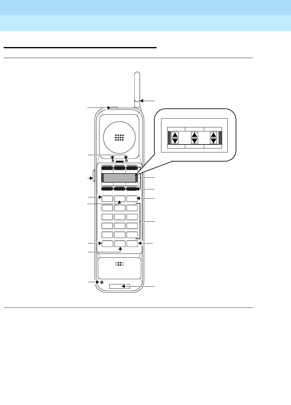
DEFINITYEnterpriseCommunicationsServerandSystem75andSystem85
Terminals and Adjuncts Reference
555-015-201 Issue 11
December 1999
Cordless and Wireless Telephones
18-12The MDW 9000 Wireless Telephone
18
The MDW 9000 Wireless Telephone
Figure 18-5. The MDW 9000 Telephone, Including Enlarged Display Area
Conf Tr ans Feat
MDW 9000
Ext.
Mute On/Off Hold
12 3
ABC DEF
4 5 6
JKL MNOGHI
7 8 9
TUV WXYZPQRS
*0#
Oper
18
ON
RANGE
PMUTE
MSG
BATT
Handset Display
Headset On/Off Button Antenna
5 Outside Line/Programmable
Drop Button
Battery Charging Contacts
Volume Control Switch
Mute Button
On/Off Button Hold Button
Feat (Feature) Button
Trans (Transfer) Button
Conf (Conference) Button
Headset Jack Handset Extension Label
Dial Pad
Intercom Buttons
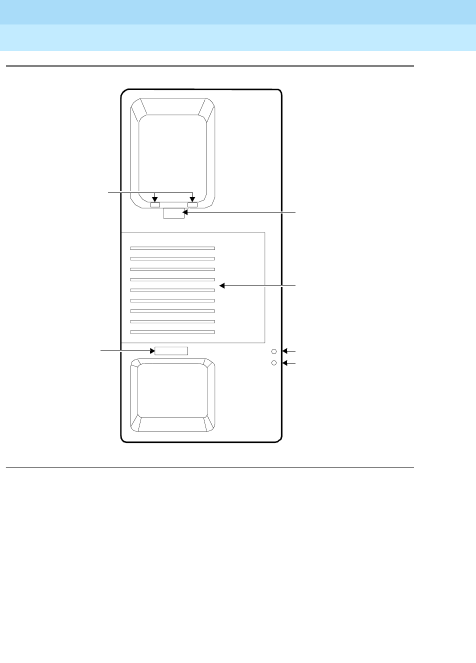
DEFINITYEnterpriseCommunicationsServerandSystem75andSystem85
Terminals and Adjuncts Reference
555-015-201 Issue 11
December 1999
Cordless and Wireless Telephones
18-13The MDW 9000 Wireless Telephone
18
Figure 18-6. The MDW 9000 Telephone, Top View of Charging Cradle
Battery
Ext. 16
Charge
Spare
Charge
Charging Cradle
Charge Indicator
Spare Charge Indicator
Spare Battery Cover
Handset Hook
Charging Contacts
Extension
Label
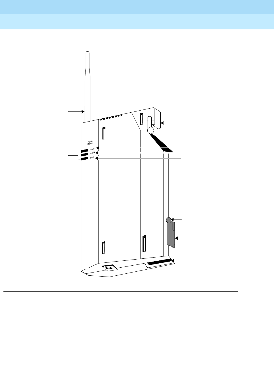
DEFINITYEnterpriseCommunicationsServerandSystem75andSystem85
Terminals and Adjuncts Reference
555-015-201 Issue 11
December 1999
Cordless and Wireless Telephones
18-14The MDW 9000 Wireless Telephone
18
Figure 18-7. The MDW 9000 Telephone, Radio Module
The MDW 9000 Wireless Telephone is part of the TransTalk™9000 Digital
Wireless System family of telephones. This wireless telephone has three basic
parts, the handset the charging cradle, and the radio module.
■The handset has line/programmable feature/intercom buttons, Drop, Mute,
Hold, Conference, and Transfer buttons, a Headset On/Off button and a
Handset On/Off button, a LCD display, a Volume control switch, battery
charging contacts, a flexible antenna, and a Headset jack.
■The charging cradle has a handset hook, a spare battery cover, a spare
battery.
Top Hook
Power Plug
Card Edge
Snap Lock
Line Connector
LED Indicators
Power
Radio
Pass
Antenna
Connector
DEFINITYEnterpriseCommunicationsServerandSystem75andSystem85
Terminals and Adjuncts Reference
555-015-201 Issue 11
December 1999
Cordless and Wireless Telephones
18-15The MDW 9000 Wireless Telephone
18
■The radio module has Power, Pass, and Radio indicator lights, a top hook,
card edge, and snap lock which connect the radio module to the carrier
assembly/backplane, an antenna, and power plug and line connectors.
In order to provide you with the freedom of mobility, the MDW 9000 is not
connected physically (by a line cord or wire from the handset) to the DEFINITY
Communications System Generic 1, Generic 2, or Generic 3, or the DEFINITY
ECS. Instead, the MDW 9000 communicates by way of a radio link to its matched
radio module, which, in turn, connects it to the DEFINITY switch or the DEFINITY
ECS. The telephone needs merely an electrical outlet, and a test check to make
sure that the handset is in range of its matching radio module.
The handset communicates through a matching radio module. When up to six
wireless phones are used within a single location, a carrier assembly is required.
When the radio modules are placed in the carrier assembly, it is considered a
radio base station.
Applications
The MDW 9000 Wireless Telephone can be used with the DEFINITY
Communications System Generic 1, Generic 2, and Generic 3, the DEFINITY
ECS, System 75, and System 85.
Physical Features
Dimensions
NOTE:
The dimensions described here for the MDW 9000 telephone are
approximate.
For the Handset:
Width = 1.5 inches
Length = 10 inches
Height = 2.43 inches
For the Cradle:
Width = 3.94 inches
Length = 9.75 inches
Height = 5.13 inches

DEFINITYEnterpriseCommunicationsServerandSystem75andSystem85
Terminals and Adjuncts Reference
555-015-201 Issue 11
December 1999
Cordless and Wireless Telephones
18-16The MDW 9000 Wireless Telephone
18
For the Radio Module:
Width = 5.5 inches
Length = 12.1 inches
Height = 1.5 inches
Handset Features
Fixed Feature Buttons
The MDW 9000 has the following eight fixed feature buttons:
■CONFERENCE button — labeled CONF
■DROP button — The DROP button is NOT labeled. It is located in the lower
right corner of the LCD display.
■TRANSFER button — labeled TRANS
■HOLD button
■FEATURE button — The Feature button (labeled FEAT) is not used.
■MUTE button — The MUTE button is used to turn on and off the
microphone associated with the handset
or
the headset.
■Headset On/Off button — This button is used for turning the headset on
and off. Located on top of the handset, it is used when the headset jack is
in use. At all other times, the Headset On/Off button is deactivated to
prevent accidental call termination.
■Handset (labeled ON/OFF) button — This On/Off button is used for turning
the handset on and off. (It can also be used to turn the headset on or off.)
Outside Line or Intercom/ Programmable Feature Buttons
When labeled with an extension number, these buttons indicate lines used for
incoming and outgoing calls (call appearances) and for using the telephone as an
intercom; when programmed and labeled with feature names, these buttons
access features (feature buttons).
LCD Display
The display provides information on the status of lines and range, battery power,
mute usage, etc. (See “Display Information” later in this section.)
Dial Pad
This is the standard 12-button pad for dialing telephone numbers and accessing
features.

DEFINITYEnterpriseCommunicationsServerandSystem75andSystem85
Terminals and Adjuncts Reference
555-015-201 Issue 11
December 1999
Cordless and Wireless Telephones
18-17The MDW 9000 Wireless Telephone
18
Volume Control Switch
The Volume control adjusts the receiver volume (higher or lower) when the
handset is off-hook and adjusts the ring volume (higher or lower) when the
handset is on-hook.
Antenna
The antenna is used for receiving the transmissions from the radio module. This
antenna is flexible and is permanently attached to the handset.
Battery Charging Contacts
These contacts are used for charging the handset when contact is made with the
charging cradle.
Headset Jack
This jack is used for connecting the headset to the handset.
Charging Cradle Features
Charge Indicator
The green Charging Indicator light on the cradle’s faceplate indicates when the
handset battery is charging. This LED is labeled Charge.
Spare Charge Indicator
The green Charge Indicator light on the cradle’s faceplate indicates when the
spare battery (in the spare battery garage) is charging. This LED is labeled
Spare Charge.
Battery Charging Contacts
The battery charging contacts are used for charging the handset when contact is
made with the charging cradle.
Handset Hook
This hook is used for hanging up the handset in the cradle.
Spare Battery Cover
The battery cover covers the spare battery garage. It opens by sliding to the left.
Modular Power Pack
This rechargeable, replaceable battery pack provides at least 3 hours of “talk time”
and should hold its charge for at least 22 hours. The power pack is located inside
the cradle.

DEFINITYEnterpriseCommunicationsServerandSystem75andSystem85
Terminals and Adjuncts Reference
555-015-201 Issue 11
December 1999
Cordless and Wireless Telephones
18-18The MDW 9000 Wireless Telephone
18
Power Cord Jack
This jack is used for connecting the power cord to your charging cradle. This cord
is then plugged into a wall outlet. This jack is located on the back of the cradle.
Radio Module Features
Power and Pass Indicator Lights
The Power and Pass lights indicate when the module is powered up and
completes its self-diagnostic. The Radio light goes on when the handset is in use.
Top Hook and Card Edge
The top hook and the card edge connect the radio module to the carrier
assembly/backplane mounting rod.
Snap Lock
This lock locks the radio module into the carrier assembly.
Antenna
The sturdy and flexible antenna sends signals between the handset and the radio
module.
Power Plug Jack
The AC adapter should be inserted into this jack.
Line Jack
The line cord should be inserted into this jack.
Display Information
The LCD Display provides visual call and telephone status information through
thefollowingsetoficons:
■or or shows the status of the adjacent button. If the triangle
and rectangle both appear, you are using that line; if only the rectangle
appears, the line is in use.
■18 appears during Local Test Mode; 0through 10 can appear during the
Wireless Test Mode.
■ON appears when the handset is on.
■RANGE flashes to indicate that you are out of range and appears steadily
when you have lost communication.
■Pis
not
used with a DEFINITY switch or System 75 or System 85.
■MUTE appears when the handset microphone is muted.

DEFINITYEnterpriseCommunicationsServerandSystem75andSystem85
Terminals and Adjuncts Reference
555-015-201 Issue 11
December 1999
Cordless and Wireless Telephones
18-19The MDW 9000 Wireless Telephone
18
■Tappears when the Wireless Test Mode is active.
■MSG appears when there is a message waiting for you.
■BATT appears when the battery is low.
Out-of-Range Indication
While the set is still active, it gives an audible indication (double beep) and visual
indication (the RANGE icon appears on the LCD display) when the handset is
getting out of range of the radio module.
Distance and Installation Limitations
The MDW 9000 uses radio transmissions to communicate. The range depends on
your particular operating environment. For indoor use, intervening walls will
reduce the phone’s range. Try to stay away from concentrations of structural
metal, such as steel and aluminum, or reinforced concrete.
At least 6 feet is required between the radio module/radio base station and the
phone system switch.
Before you install the radio module or radio base station, note the following
considerations:
■When positioning the radio module or radio base station, try to place the
unit in a central location, relative to the handset usage area. If your switch
is located in a distant area, you may have to run line cord from your phone
system to the centrally positioned radio module(s). The maximum distance
is 1000 feet of 26 gauge cable.
■The radio module or radio base station should not share the same power
line or be within 6 feet of equipment with microprocessors such as
answering machines, personal computers, and fax machines, or
electromagnetic equipment such as electric motors.
■For remote locations, an individual radio module can be installed in that
area and attached via line cord to the phone system. IROBs should be
used in outdoor area.
■The radio module or radio base station should be placed high on the wall
for optimum voice quality and range. Allow at least 1 foot of space between
the top of the antenna on the radio module(s) and the ceiling.
■Install the single radio module within 3 feet of either side of, and within
6-8 feet above, a properly grounded 3-prong electrical outlet that is not
controlled by an on/off switch.
■Install the radio base stations within 15 feet of either side of, and within
6-8 feet above, a properly grounded 3-prong electrical outlet that is not
controlled by an on/off switch.

DEFINITYEnterpriseCommunicationsServerandSystem75andSystem85
Terminals and Adjuncts Reference
555-015-201 Issue 11
December 1999
Cordless and Wireless Telephones
18-20The MDW 9000 Wireless Telephone
18
■If your phone system uses an uninterruptible power supply, such as a
backup generator, be sure to connect the radio or radio base station to that
power supply.
Switch Administration
Aliasing
For all System 75 and System 85 releases and DEFINITY Generic 1, Generic 2,
and Generic 3, Versions 1 and 2, the MDW 9000 terminal must be administered
as a 7303S Hybrid terminal.
If your MDW 9000 is connected to a DEFINITY Generic 3, Version 3 (or later), the
MDW 9000 can be administered as itself.
For the System 85, R2V1 through R2V4 switch which does not accommodate
Universal modules, an ANN17B Hybrid pack in conjunction with a DS-1 carrier
must be used to connect the switch and the MDW 9000 terminal. On all other
switches, including System 75, a DEFINITY Generic 1 and Generic 3, or a
DEFINITY ECS, a TN62B Hybrid pack must be used with the Universal carrier for
this purpose.
NOTE:
A DEFINITY Generic 2 may use either an ANN17B or a TN62B pack. In
either case, the latest vintage packs are recommended.
Button Numbering
Only the system manager should administer feature button assignments on the
telephone. It is recommended that you not use a feature that requires visuals (that
is, the light next to each administrable button) to be updated while the set is turned
off, or any feature that may be activated by button depression while the set is
turned off (for example, Send All Calls).
Use Figure 18-8 for button numbering on the MDW 9000 set when it is connected
to a System 75, a DEFINITY Generic 1, Generic 3 switch, or a DEFINITY ECS.
Use Figure 18-9 for button numbering on the MDW 9000 set when it is connected
toaSystem85oraDEFINITYGeneric2.
NOTE:
On System 75, a DEFINITY Generic 1 and 3, or a DEFINITY ECS, button
numbering begins with “1,” the button on the upper right of the display. On
System 85 and a DEFINITY Generic 2, button numbering starts
with “3.”
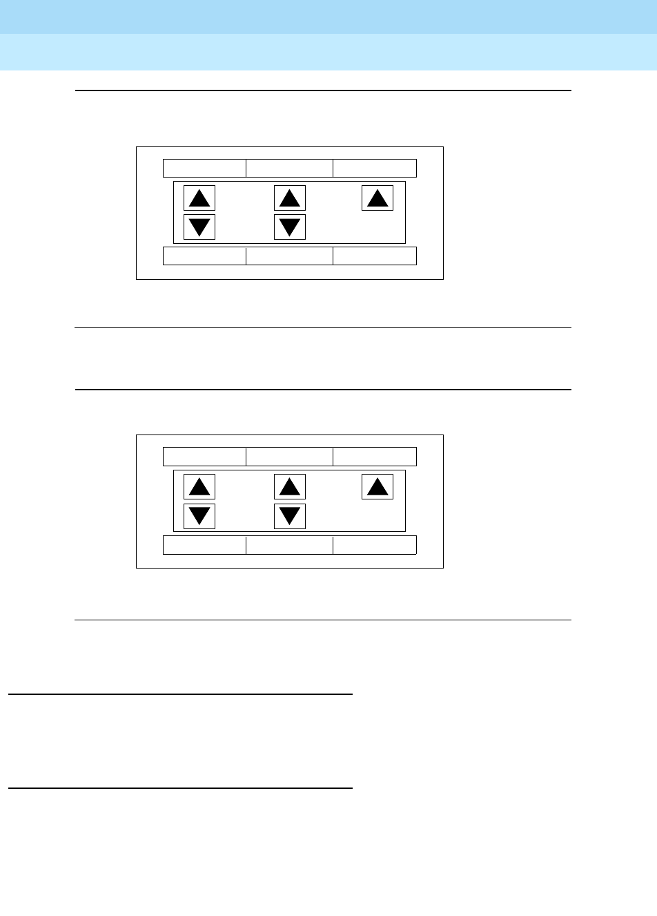
DEFINITYEnterpriseCommunicationsServerandSystem75andSystem85
Terminals and Adjuncts Reference
555-015-201 Issue 11
December 1999
Cordless and Wireless Telephones
18-21The MDW 9000 Wireless Telephone
18
Figure 18-8. Button Numbering for an MDW 9000 Connected to a System 75,
a DEFINITY Generic 1 or 3, or a DEFINITY ECS
Figure 18-9. Button Numbering for an MDW 9000 Connected to a
System 85 or a DEFINITY Generic 2
FCC Registration
The MDW 9000 telephone has been tested and has been found to comply with
FCC Part 15 Rules.
Hearing Aid Compatibility
This wireless telephone is compatible with inductively-coupled hearing aids.
ON
RANGE
PMUTE
MSG
BATT
321
5 4 DROP
10
ON
RANGE
PMUTE
MSG
BATT
543
7 6 DROP
10

DEFINITYEnterpriseCommunicationsServerandSystem75andSystem85
Terminals and Adjuncts Reference
555-015-201 Issue 11
December 1999
Cordless and Wireless Telephones
18-22The MDW 9000 Wireless Telephone
18
UL and CSA Approval
This voice terminal has been tested and has met the Underwriters Laboratories
(UL) Standards UL 1459 and have also met the Canadian Standards Association
(CSA) Standards CSA-C22.2 No.225-M90.
MDW 9000 Equipment PECs and Comcodes
The MDW 9000 telephone and components can be ordered with these PECs and
Comcodes:
■MDW 9000 Telephone (sold separately)
Black = PEC: 3204-01B
Comcode: 107017022
White = PEC: 3204-01B
Comcode: 107017030
■MDW 9000 Multiple Unit (sold as a unit)
Black = PEC: 3204-W1B
Comcode: 107077444
White = PEC: 3204-W1W
Comcode: 107077463
■Carrier Assembly/Backplane
PEC: 3204-CR1
Comcode: 107073330
■Headset
PEC: 3122-041
■Battery Pack
Black = PEC: 32036
Comcode: 106760804
White = PEC: 32034
Comcode: 106760812
■Holster
Gray
Comcode: 846628527
Black
Comcode: 846501401
■8-foot Line Cord
Comcode: 103786794
■Charging Cradle
Black = PEC: 107076754
White = PEC: 107076762
■Carrier Assembly
Comcode: 107073330

DEFINITYEnterpriseCommunicationsServerandSystem75andSystem85
Terminals and Adjuncts Reference
555-015-201 Issue 11
December 1999
Cordless and Wireless Telephones
18-23The MDW 9000 Wireless Telephone
18
■Carrier Assembly AC Adapter
Comcode: 847224227
■Radio Module AC Adapter
Comcode: 847180890
■Charging Cradle AC Adapter
Comcode: 847180890
Additional Documents
The following documents contain additional information relating to the MDW 9000
Wireless Telephone: (Use the 9 digit number listed after each document to order
that book from the BCS Publications Center for Lucent Technologies.)
■
DEFINITY Generic 1, 2, and 3, System 75 and System 85 MDW 9000
Wireless Telephone User’s Guide
, 555-230-768
■
MDW 9000 Wireless Telephone Installation Manual
, 503-801-111
■
MDW 9000 Wireless Telephone Quick Reference
, 503-801-110
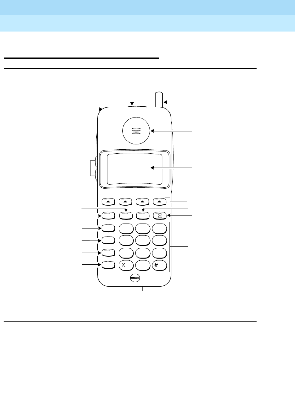
DEFINITYEnterpriseCommunicationsServerandSystem75andSystem85
Terminals and Adjuncts Reference
555-015-201 Issue 11
December 1999
Cordless and Wireless Telephones
18-24The MDW 9031DCP Wireless Pocket Phone
18
The MDW 9031DCP Wireless Pocket
Phone
Figure 18-10. The MDW 9031DCP Wireless Pocket Phone
Redial
Feat/P
Conf
Trans
Hold
MenuMute
123
ABC DEF
456
JKL MNOGHI
789
TUV WXYZPQRS
0OPER
Antenna
Receiver
Handset display
with Backlighting
Column buttons
M
Mute button
Select button
Dial pad
Headset connector
Hold button
Transfer button
Conference button
Feature/Program
button
On/Off button
Redial button
Volume control
Lanyard loop
Headset On/Off button
On/Off
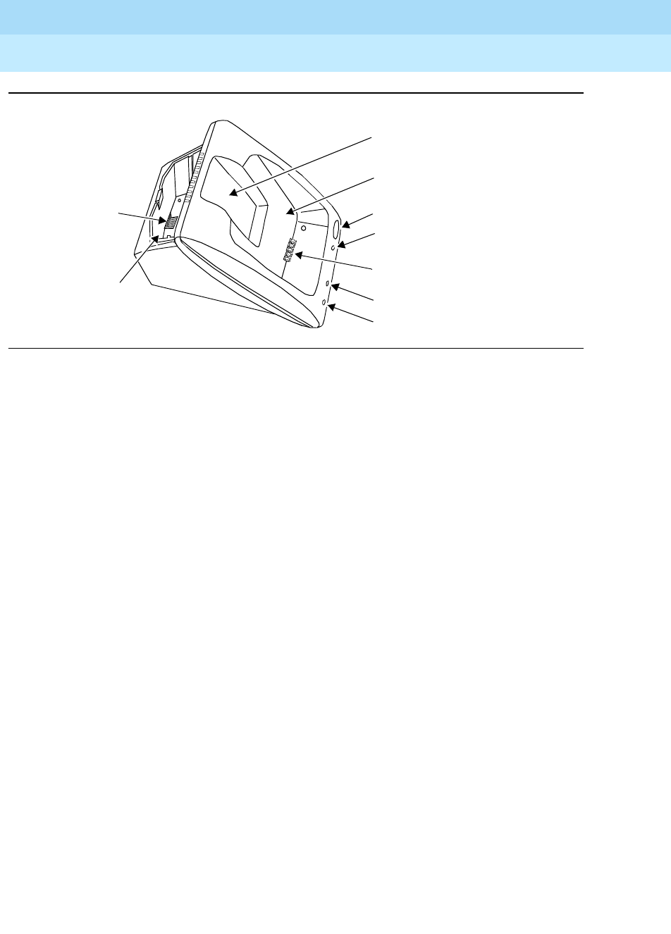
DEFINITYEnterpriseCommunicationsServerandSystem75andSystem85
Terminals and Adjuncts Reference
555-015-201 Issue 11
December 1999
Cordless and Wireless Telephones
18-25The MDW 9031DCP Wireless Pocket Phone
18
Figure 18-11. The Battery Charger
REFRESH Button
REFRESH LED
Handset Cradle Battery Contacts
HANDSET LED
SPARE LED
Handset Cradle
“Battery Charge State Label”
Spare Battery
Compartment
Battery Contacts
Spare Battery
Compartment
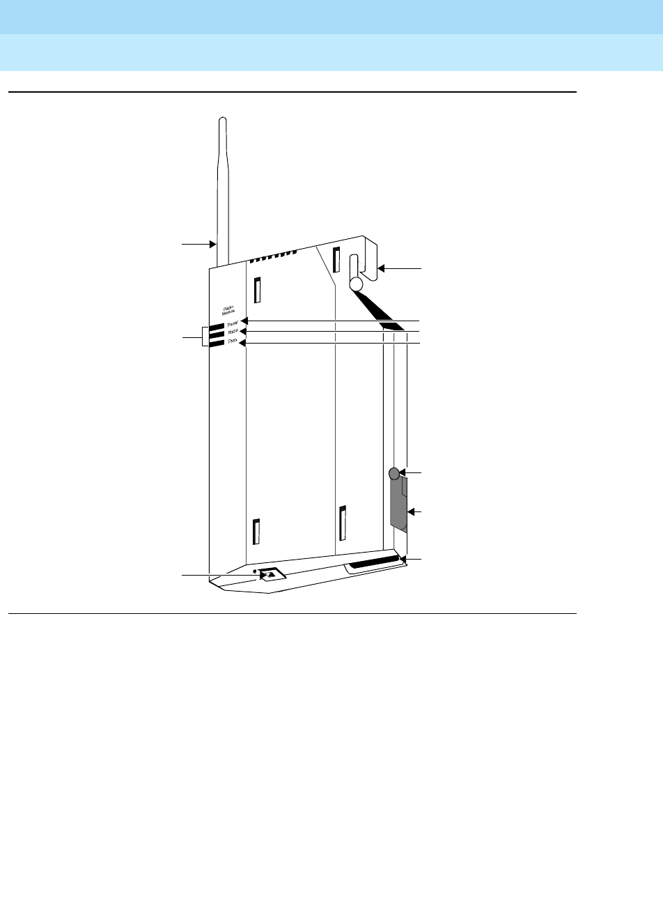
DEFINITYEnterpriseCommunicationsServerandSystem75andSystem85
Terminals and Adjuncts Reference
555-015-201 Issue 11
December 1999
Cordless and Wireless Telephones
18-26The MDW 9031DCP Wireless Pocket Phone
18
Figure 18-12. The MDW 9031DCP Wireless Pocket Phone, Radio Module
Top Hook
Power Plug Connector
Card Edge
Snap Lock
Line Connector
LED Indicators
Power LED
Radio LED
Pass LED
Antenna

DEFINITYEnterpriseCommunicationsServerandSystem75andSystem85
Terminals and Adjuncts Reference
555-015-201 Issue 11
December 1999
Cordless and Wireless Telephones
18-27The MDW 9031DCP Wireless Pocket Phone
18
The MDW 9031DCP Wireless Pocket Phone is part of the TransTalk™9000 Digital
Wireless System family of telephones. This phone comes in two models, the
single-zone model and the dual-zone model, according to whether the phone will
be connected to one radio module (a single-zone configuration) or two radio
modules (a dual-zone configuration).
This wireless Pocket Phone has three basic parts, the handset the battery
charger, and the radio module.
■The handset has line/programmable feature/intercom buttons, Mute, Hold,
Conference, and Transfer buttons, a Headset On/Off button and a Handset
On/Off button, a LCD display with Backlighting, a Volume control, battery
charging contacts, a flexible antenna, and a Headset jack.
■The battery charger has a handset hook, a spare battery cover, and a
spare battery.
■The radio module has Power, Pass, and Radio indicator lights, and a top
hook, card edge, and snap lock which connect the radio module to the
carrier assembly/backplane, an antenna, and power plug, and line
connectors.
In order to provide you with the freedom of mobility, the MDW9031DCP is not
connected physically (by a line cord or wire from the handset) to the DEFINITY
Communications System Generic 1, Generic 2, or Generic 3, or the DEFINITY
ECS. Instead, the MDW 9031DCP communicates by way of a radio link to its
matched radio module, which, in turn, connects it to the DEFINITY switch or the
DEFINITY ECS. The telephone needs merely an electrical outlet, and a test check
to make sure that the handset is in range of its matching radio module.
The handset communicates through a matching radio module. When up to six
wireless phones are used within a single location, a carrier assembly is required.
The Dual Zone model allows you to link up with either of two different radio
modules, thereby expanding the coverage area since you are able to use the
same phone to place and answer calls for the radio module in Zone 1 or the radio
module in Zone 2.
NOTE:
Dual Zone installations require two station ports — one for each radio
module.
Applications
The MDW 9031DCP Wireless Pocket Phone, both single-zone and dual-zone
models, can be used with the DEFINITY Communications System Generic 1,
Generic 2, and Generic 3, the DEFINITY ECS, System 75, and System 85.

DEFINITYEnterpriseCommunicationsServerandSystem75andSystem85
Terminals and Adjuncts Reference
555-015-201 Issue 11
December 1999
Cordless and Wireless Telephones
18-28The MDW 9031DCP Wireless Pocket Phone
18
Physical Features
Dimensions
NOTE:
The dimensions described here for the MDW 9031DCP Pocket Phone are
approximate.
For the Handset:
Width = 2.25 inches
Length = 6 inches
Depth = 1.0 inches
Weight: 33 pounds
For the Battery Charger:
Width = 3.94 inches
Length = 9.75 inches
Height = 5.13 inches
For the Radio Module:
Width = 5.5 inches
Length = 12.1 inches
Height = 1.5 inches
Handset Features
Fixed Feature Buttons
The MDW 9031DCP Pocket Phone has the following ten types of fixed feature
buttons:
■CONFERENCE button — labeled CONF
■TRANSFER button — labeled TRANS
■HOLD button
■FEATURE/PROGRAMMING button — The Feature button (labeled
FEAT/P) is not used for DEFINITY features.
■MUTE button — The MUTE button is used to turn on and off the
microphone associated with the handset
or
the headset.
■REDIAL button — The REDIAL button is used to redial the last number you
dialed from the dial pad.
■SELECT button — The SELECT button (labeled ) is used to move the
Selection rectangle, and together with the Column buttons, to choose a line
or programmable/intercom/drop button. It is also used to wake-up the
phone.

DEFINITYEnterpriseCommunicationsServerandSystem75andSystem85
Terminals and Adjuncts Reference
555-015-201 Issue 11
December 1999
Cordless and Wireless Telephones
18-29The MDW 9031DCP Wireless Pocket Phone
18
■Four COLUMN buttons — these buttons (labeled ) are used together
with the SELECT button to choose a line or programmable/intercom/drop
button.
■Headset On/Off button — This button is used for turning the headset on
and off. Located on top of the handset, it is used when the headset jack is
in use. At all other times, the Headset On/Off button is deactivated to
prevent accidental call termination.
■Handset (labeled ON/OFF) button — This On/Off button is used for turning
the handset on and off. (It can also be used to turn the headset on or off.)
LCD Display
The display provides information on the status of lines and range, battery power,
mute usage, etc.
Dial Pad
This is the standard 12-button pad for dialing telephone numbers and accessing
features.
Volume Control Switch
The Volume control (labeled “+”and“-”) adjusts the receiver volume (higher or
lower) when the handset is off-hook and adjusts the ring volume (higher or lower)
when the handset is on-hook.
Antenna
The antenna is used for receiving the transmissions from the radio module. This
antenna is flexible and is permanently attached to the handset.
Battery Charging Contacts
These contacts are used for charging the handset when contact is made with the
charging cradle.
Headset Connector
This jack is used for connecting the headset to the handset.
Battery Charger Features
Spare Battery Compartment
The Spare battery compartment refreshes the battery pack automatically by fully
discharging it before recharging it. This process reduces or eliminates the
potential “Memory” effect (which reduces a battery’s capacity when you
repeatedly recharge a battery before it is fully discharged).

DEFINITYEnterpriseCommunicationsServerandSystem75andSystem85
Terminals and Adjuncts Reference
555-015-201 Issue 11
December 1999
Cordless and Wireless Telephones
18-30The MDW 9031DCP Wireless Pocket Phone
18
Handset Cradle
The handset cradle charges a battery pack in the handset.
REFRESH button and Indicator
When you press the REFRESH button, the battery pack in the handset cradle is
refreshed by fully discharging the battery pack before recharging it. While the
battery pack is being discharged, the REFRESH and HANDSET lights go on.
HANDSET Indicator
The HANDSET light goes on when the handset battery pack is installed in the
handset and the handset is inserted correctly into the battery charger handset
cradle.
SPARE Indicator
The SPARE Battery Pack light goes on when a battery pack is positioned correctly
in the Spare battery compartment.
Battery Charging Contacts
The battery charging contacts are used for charging the handset when contact is
made with the charging cradle.
Radio Module Features
Power and Pass Indicators
The Power and Pass lights indicate when the module is powered up and
completes its self-diagnostic. The Radio indicator light goes on when the handset
is in use.
Top Hook and Card Edge
The top hook and the card edge connect the radio module to the carrier
assembly/backplane mounting rod.
Snap Lock
This lock locks the radio module into the carrier assembly.
Antenna
The sturdy and flexible antenna sends signals between the handset and the radio
module.
Power Plug Jack
The AC adapter should be inserted into this jack.

DEFINITYEnterpriseCommunicationsServerandSystem75andSystem85
Terminals and Adjuncts Reference
555-015-201 Issue 11
December 1999
Cordless and Wireless Telephones
18-31The MDW 9031DCP Wireless Pocket Phone
18
Line Jack
The line cord should be inserted into this jack.
Out-of-Range Indication
While the set is still active, it gives an audible indication (double beep) and visual
indication (the RANGE icon appears on the LCD display) when the handset is
getting out of range of the radio module.
Distance and Installation Limitations
Both the MDW 9031 DCP single-zone and the dual-zone Pocket Phones can be
installed in a single user configuration or a multiple user configuration with up to
30 handsets.
The MDW 9031DCP uses radio transmissions to communicate. The range
depends on your particular operating environment. For indoor use, intervening
walls will reduce the phone’s range. Try to stay away from concentrations of
structural metal, such as steel and aluminum, or reinforced concrete.
NOTE:
At least 6 feet is required between the radio module or carrier and the phone
system switch.
For each radio module or carrier you install, note the following considerations:
■The radio module or carrier(s) should not be within 3-feet of any large
metal object and should not have metal objects in the line of sight to the
operating area of the handset.
■The radio module or carrier(s) should not be within 6 feet of equipment with
microprocessors such as answering machines, personal computers, and
fax machines; control units, communications system switches, or other
phones (especially speakerphones); competing radio devices such as
wireless bar-code scanners; electromagnetic equipment such as electric
motors; or electrical main power feeds, junction boxes, circuit-breaker
panels, fuse boxes, or 220-volt power lines.
■The radio module or carrier(s) should not share the same power line as
equipment with microprocessors such as answering machines, personal
computers, and fax machines, or electromagnetic equipment such as
electric motors.
■If your phone system uses an uninterruptible power supply, such as a
backup generator, be sure to connect the radio or carrier(s) to that power
supply.
Follow these additional rules for installing each radio module:

DEFINITYEnterpriseCommunicationsServerandSystem75andSystem85
Terminals and Adjuncts Reference
555-015-201 Issue 11
December 1999
Cordless and Wireless Telephones
18-32The MDW 9031DCP Wireless Pocket Phone
18
■Installing a single radio module on a shelf or desk is not recommended
because it greatly reduces the range and quality of the transmission.
■Install a single radio module within 3 feet of either side of, and within
6-12 feet above, a properly grounded 3-prong electrical outlet that is not
controlled by an on/off switch.
■For remote locations, an individual radio module can be installed in that
area and attached via telephone line cord to the phone system. IROBs
must be used for out-of-building installations.
!CAUTION:
A radio module cannot be installed outdoors.
■The radio module should be placed high on the wall for optimum voice
quality and range. Allow at least 1 foot of space between the top of the
antenna on the radio module(s) and the ceiling.
■When installing the MDW 9031DCP Dual Zone Pocket Phone in the same
building, you should limit how much zone overlap there is between radio
module 1 and radio module 2. NO OVERLAP is ideal; minimal overlap
between zones is also recommended.
If there is an extensive overlap condition, there will be interference between
the radio modules, causing poor voice quality as well as rendering the
handset inoperable. In the latter case, the RANGE icon will appear in the
handset display.
Follow these additional rules for installing one or more carriers:
■Install carrier(s) within 15 feet of either side of, and within 6 to 8 feet above,
a properly grounded 3-prong electrical outlet that is not controlled by an
on/off switch.
■Choose a location where handset users will not approach the carrier(s)
within a radius of 6 feet for 1 or 2 carriers or 10 feet for 3 carriers.
■When installing multiple carriers:
— Install multiple carriers 1 foot optimally to 4 feet apart.
— Install multiple carriers on the same horizontal axis (that is, do not
install one carrier higher or lower than another)
— Install the control carrier as the leftmost carrier, using only the
expansion cables provided.
— Slot 6 of an 117A3 control carrier must always contain a radio
module to pass the synchronization signal to the next carrier.
!CAUTION:
Carrier(s) cannot be installed outdoors.
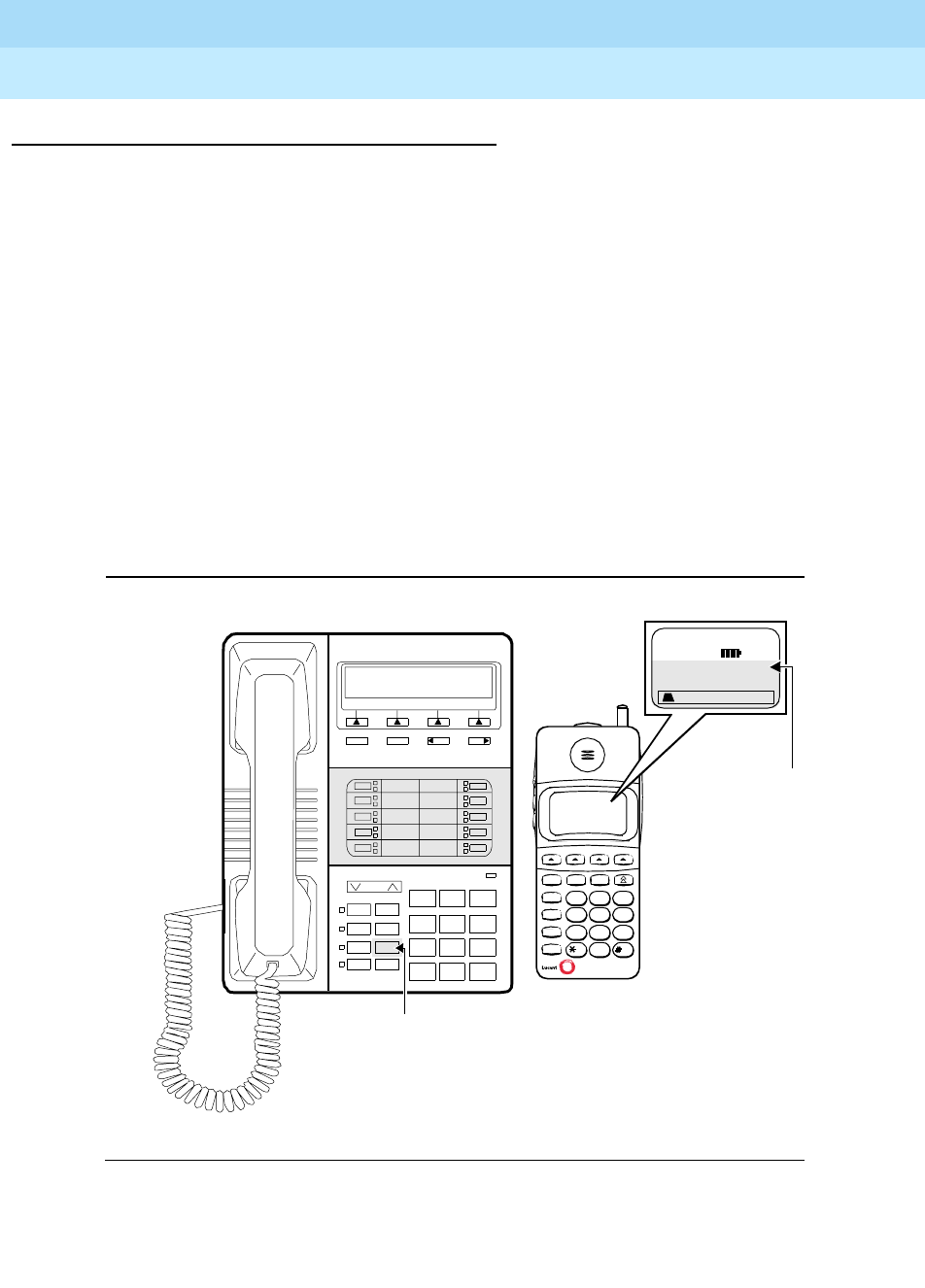
DEFINITYEnterpriseCommunicationsServerandSystem75andSystem85
Terminals and Adjuncts Reference
555-015-201 Issue 11
December 1999
Cordless and Wireless Telephones
18-33The MDW 9031DCP Wireless Pocket Phone
18
Switch Administration
Aliasing
For all System 75 and System 85 releases and DEFINITY Generic 1, Generic 2,
and Generic 3, Versions 1 and 2, the MDW 9031DCP Pocket Phone must be
administered as an 8410D voice terminal.
For the MDW 9030DCP Dual Zone phones connected to a DEFINITY system prior
to Release 5.0, you must administer two station ports (2 extensions) — one for
each radio module. Each station port must be administered with three call
appearances of its own and three call appearances of the other station extension
number.
Button Numbering
Use Figure 18-8 for button numbering on the MDW 9031DCP when it is
connected to a DEFINITY switch.
Figure 18-13. Button Numbering for an MDW 9031DCP Connected to a
System 75, a DEFINITY Generic 1 or 3, or a DEFINITY ECS
Volume
Ring
08
Test
06
Mut e
04
Speaker
0A
123
456
789
ABC DEF
MNOJKLGHI
PQRS TUV WXYZ
*
O#
8410D
NextPrevMenu Exit
Message
A
B
C
1
2
3
4
5
6
7
Redial
Feat/P
Conf
Trans
Hold
Menu
Mut e
123
ABC DEF
456
JKL MNOGHI
789
TUV WXYZPQRS
0
OPER
On/Off
5
1
6
3
B
7
3
C
8
4
D
A
Button “8” on the
9031DCP is the
Scroll button
(non-programmable)
04 = Button D “Drop”

DEFINITYEnterpriseCommunicationsServerandSystem75andSystem85
Terminals and Adjuncts Reference
555-015-201 Issue 11
December 1999
Cordless and Wireless Telephones
18-34The MDW 9031DCP Wireless Pocket Phone
18
FCC Registration
The MDW 9031DCP Pocket Phone has been tested and has been found to
comply with FCC Part 15 Rules.
Hearing Aid Compatibility
The MDW 9031DCP is compatible with inductively-coupled hearing aids.
UL and CSA Approval
The MDW 9031DCP has been tested and has met the Underwriters Laboratories
(UL) Standards UL 1459 and have also met the Canadian Standards Association
(CSA) Standards CSA-C22.2 No.225-M90.
MDW 9031DCP Equipment PECs and Comcodes
The MDW 9031DCP Pocket Phone and components can be ordered with these
PECs and Comcodes:
■MDW 9031DCP Single Zone Pocket Phone System (Stand-Alone)
includes Radio Module and Kit of Parts
PEC: 3204-07B
For Pocket Phone – Comcode: 108046525
For Kit of Parts – Comcode: 107586828
■MDW 9031DCP Single Zone Pocket Phone System
(requires Carrier), includes Radio Module, but not Kit of Parts
PEC: 3204-W7B
Comcode: 108046525
■MDW 9031DCP Dual Zone Pocket Phone System (Stand-Alone)
includes 2 Radio Modules and Kit of Parts
PEC: 3229-SDZ
For Pocket Phone – Comcode: 108401555
For Kit of Parts – Comcode: 107586828
■MDW 9031DCP Dual Zone Pocket Phone System
(requires Carrier), includes 2 Radio Modules, but not Kit of Parts
PEC: 3229-MDZ
Comcode: 108401555
■Retractable Flex Antenna for MDW9031DCP Pocket Phone Handset
Comcode: 847713450
■Carrier – includes:
Power Cord (25 foot) and AC Adapter for Carrier and
Expansion Cable (6 foot) for Multiple-Carrier Installation

DEFINITYEnterpriseCommunicationsServerandSystem75andSystem85
Terminals and Adjuncts Reference
555-015-201 Issue 11
December 1999
Cordless and Wireless Telephones
18-35The MDW 9031DCP Wireless Pocket Phone
18
PEC: 3204-CR3A
For 117A3 Carrier – Comcode: 107907289
For 117A4 Carrier – Comcode: 107955122
Power Cord (25 feet) and AC Adapter for Carrier
Comcode: 847224227
Expansion Cable (6 foot) for Multiple-Carrier Installation
PEC: 32035A
Comcode: 847667870
■Standard Battery Pack, includes Carrying Clip
PEC: 32045A
Comcode: 107733107
Carrying Clip for Standard Battery Pack
Comcode: 847773140
Extended Battery Pack, includes Carrying Clip
PEC: 32049A
Comcode: 107733115
Carrying Clip for Extended Battery Pack
Comcode: 847773157
■Battery Charger, includes Power Cord (11 foot) and AC Adapter
PEC: 32047A
Comcode: 107733099
Power Cord (11 foot) and AC Adapter for Battery Charger
Comcode: 847713583
■MDW9031DCP Pocket Phone Leather Carrying Case
PEC: 32043A
Comcode: 847877487
MDW9031DCP Pocket Phone Leather Carrying Case
customized for headset use
PEC: 32090A
Comcode: 848026092
■Lanyard
Comcode: 407183417
■Telephone Line Cord (8 feet)
Comcode: 103786794
■Supra 9031 Headset with Adapter
PEC: 3123-152A
For Headset – Comcode: 407654490
For Adapter – Comcode: 848047965
9031 Quick Disconnect Adapter for Supra 9031 or Radium Headset
PEC: 3124-RCA
Comcode: 848047965
Radium (Over the Ear) Headset with Adapter
PEC: 3123-153A
For Headset – Comcode: 407720739
For Adapter – Comcode: 848047965

DEFINITYEnterpriseCommunicationsServerandSystem75andSystem85
Terminals and Adjuncts Reference
555-015-201 Issue 11
December 1999
Cordless and Wireless Telephones
18-36The MDW 9031DCP Wireless Pocket Phone
18
■Kit of Parts (for Stand-Alone Installations)
includes Power Cord (11 foot) and AC Adapter for Radio Module
PEC: D-182866
Comcode: 107586828
Additional Documents
The following documents contain additional information relating to the
MDW9031DCP Wireless Pocket Phone: (Use the 9 digit number listed after each
document to order that book from the BCS Publications Center for Lucent
Technologies.)
■
TransTalk 9000 Digital Wireless System MDW9031DCP Wireless Pocket
Phone Installation and Use,
503-801-166
■
MDW 9031/9031DCP Wireless Pocket Phone Quick Reference,
503-801-165

Other Voice Terminals
19-1Voice Terminals Reusable from Other Systems
19
DEFINITYEnterpriseCommunicationsServerandSystem75andSystem85
Terminals and Adjuncts Reference
555-015-201 Issue 11
December 1999
19
Other Voice Terminals
Voice Terminals Reusable from Other
Systems
The customer may have voice terminals that were used with a previous system
that are compatible with System 75 and System 85. The installation of these
reusable voice terminals in a System 75 or System 85 is possible, but not
recommended.
Advantages of Reusable Terminals
The main advantage of reusable terminals is a modest cost savings.
Disadvantages of Reusable Terminals
Reusable terminals have the following disadvantages:
■No access to data communications
■Incompatible with System 75 and System 85 adjuncts
■No alphanumeric displays
■Difficult administration

DEFINITYEnterpriseCommunicationsServerandSystem75andSystem85
Terminals and Adjuncts Reference
555-015-201 Issue 11
December 1999
Other Voice Terminals
19-2Models 7302H, 7303H, 7305H01B, and 7305H02B
19
Models 7302H, 7303H, 7305H01B, and
7305H02B
These MERLIN Communication System voice terminals are similar in appearance
and functions to System 75 and System 85 multi-appearance terminals.
The 7302H is a 5-button voice terminal that can be desk or wall mounted. This set
can no longer be ordered.
The 7303H is a 10-button voice terminal that can be desk or wall mounted. This
set can no longer be ordered.
The 7305H series is a 34-button voice terminal. This terminal can be equipped
with or without different features such as built-in speakerphone or display. Some
versions of the 34-button series can be ordered using PEC code 3162 and the
appropriate suffix.
Multi-Button Electronic Telephone
(MET) Sets
These DIMENSION®PBX voice terminals have some of the capabilities of
System 75 and System 85 multi-appearance terminals.
The MET sets are available in 10-, 20-, and 30-button versions. (See Figures 19-1
through 19-5.) These three types of MET sets can be used with DEFINITY
Generic 1, Generic 2, and Generic 3, a DEFINITY ECS, System 75, and System
85. The 10-button version can be desk or wall mounted. All the others must be
desk mounted. The 10-button version can be equipped with a built-in
speakerphone. The MET sets can be ordered using PEC code 3140 and the
appropriate suffix.
NOTE:
On System 85 and DEFINITY G2, the bottom five buttons on a MET set
become fixed feature buttons. On a 5-button MET set, that leaves no room
for call appearances. Therefore, the 5-button MET set
cannot
be used with
System 85 and DEFINITY G2.
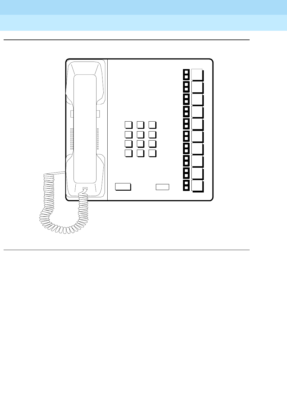
DEFINITYEnterpriseCommunicationsServerandSystem75andSystem85
Terminals and Adjuncts Reference
555-015-201 Issue 11
December 1999
Other Voice Terminals
19-3Multi-Button Electronic Telephone (MET) Sets
19
Figure 19-1. The 10-Button MET (Desk) Set
123
456
789
ABC DEF
MNOJKLGHI
PRS TUV WXY
*
O#
123
456
789
ABC DEF
MNOJKLGHI
PRS TUV WXY
*
O#
OPER
R
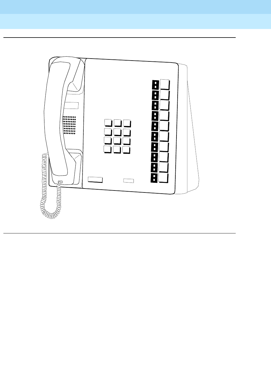
DEFINITYEnterpriseCommunicationsServerandSystem75andSystem85
Terminals and Adjuncts Reference
555-015-201 Issue 11
December 1999
Other Voice Terminals
19-4Multi-Button Electronic Telephone (MET) Sets
19
Figure 19-2. The 10-Button MET (Wall) Set
123
456
789
ABCDEF
MNO
JKL
GHI
PRSTUVWXY
*
O#
123
456
789
ABCDEF
MNO
JKL
GHI
PRSTUVWXY
*
O#
OPER
R
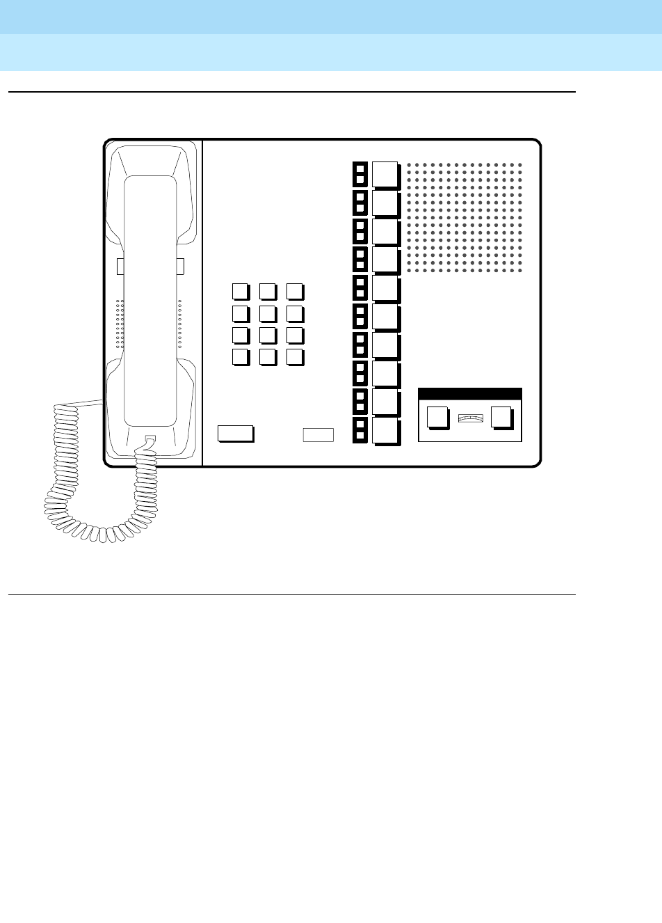
DEFINITYEnterpriseCommunicationsServerandSystem75andSystem85
Terminals and Adjuncts Reference
555-015-201 Issue 11
December 1999
Other Voice Terminals
19-5Multi-Button Electronic Telephone (MET) Sets
19
Figure 19-3. The 10-Button MET Set with Speakerphone
123
456
789
ABC DEF
MNOJKLGHI
PRS TUV WXY
*
O#
123
456
789
ABC DEF
MNOJKLGHI
PRS TUV WXY
*
O#
R
OFF
ON
QUIET
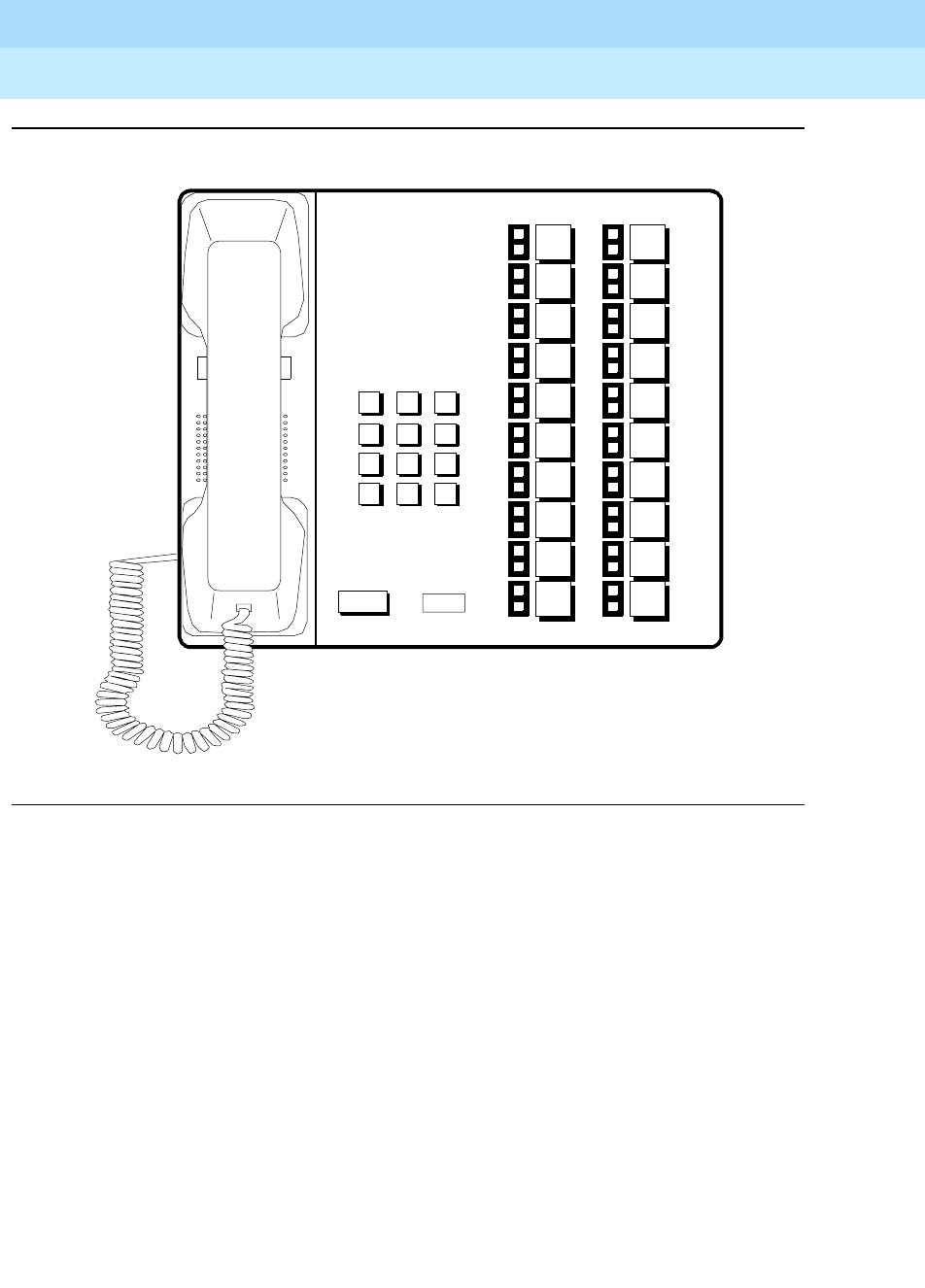
DEFINITYEnterpriseCommunicationsServerandSystem75andSystem85
Terminals and Adjuncts Reference
555-015-201 Issue 11
December 1999
Other Voice Terminals
19-6Multi-Button Electronic Telephone (MET) Sets
19
Figure 19-4. The 20-Button MET (Desk) Set
123
456
789
ABC DEF
MNOJKLGHI
PRS TUV WXY
*
O#
123
456
789
ABC DEF
MNOJKLGHI
PRS TUV WXY
*
O#
R
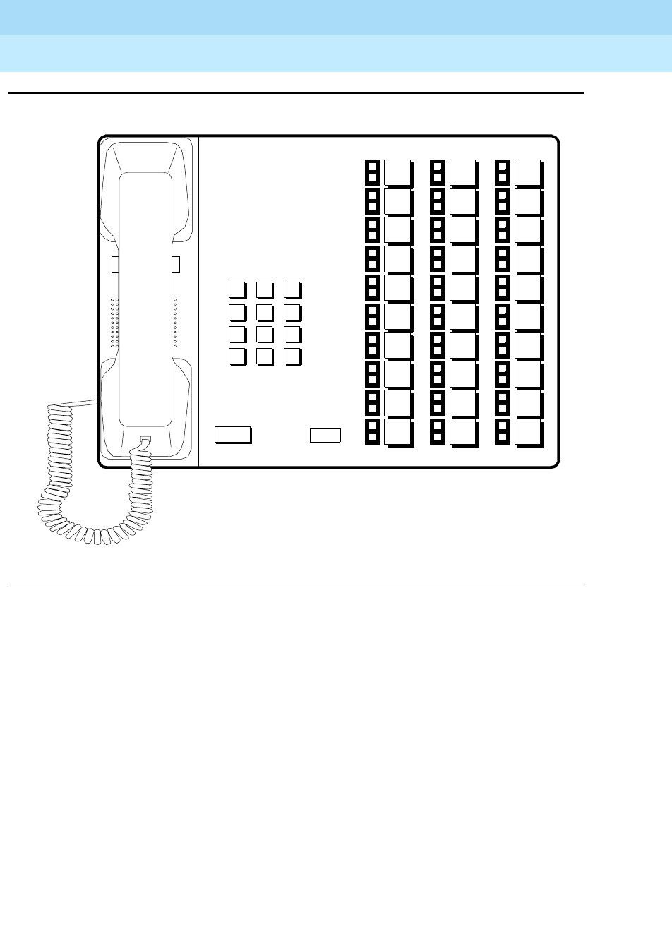
DEFINITYEnterpriseCommunicationsServerandSystem75andSystem85
Terminals and Adjuncts Reference
555-015-201 Issue 11
December 1999
Other Voice Terminals
19-7Multi-Button Electronic Telephone (MET) Sets
19
Figure 19-5. The 30-Button MET (Desk) Set
123
456
789
ABC DEF
MNOJKLGHI
PRS TUV WXY
*
O#
123
456
789
ABC DEF
MNOJKLGHI
PRS TUV WXY
*
O#
R

DEFINITYEnterpriseCommunicationsServerandSystem75andSystem85
Terminals and Adjuncts Reference
555-015-201 Issue 11
December 1999
Other Voice Terminals
19-8Multi-Button Electronic Telephone (MET) Sets
19

Adjuncts
20-1
20
DEFINITYEnterpriseCommunicationsServerandSystem75andSystem85
Terminals and Adjuncts Reference
555-015-201 Issue 11
December 1999
20
Adjuncts
This section describes the devices that can be used with voice terminals to
supplement services and features. The information provided here includes
specifics on the controls, buttons, lights, and functions of voice terminal adjuncts
that can be connected to the DEFINITY Communications System Generic 1,
Generic 2, and Generic 3, the DEFINITY ECS, System 75, and System 85.
Adjuncts that are identical in appearance and function, but have different codes,
are covered under the same heading. Adjuncts that are basically data modules
are covered in the Data Modules section later in this manual.
The adjuncts covered in this section are:
■Call Coverage Modules
■Digital Display Modules
■Function Key Modules
■Expansion Modules
■100A Tip/Ring Module
■Headset Adapters
■Z34A Message Waiting Indicator
■Speakerphones
■Loudspeaker
■7404D (Voice Terminal) Messaging Cartridge
■2870A1 37Automatic Dialer

DEFINITYEnterpriseCommunicationsServerandSystem75andSystem85
Terminals and Adjuncts Reference
555-015-201 Issue 11
December 1999
Adjuncts
20-2Call Coverage Modules
20
Call Coverage Modules
Figure 20-1. The C201A Call Coverage Module Mounted on a 7434D Voice Terminal
123
456
789
ABC DEF
MNOJKLGHI
PRS TUV WXY
*
O#
Oper
Conference
Drop
Transfer
Hold
Message
Select
Ring
7434D Voice Terminal
C201A Call Coverage Module
Indicator
Lights
Buttons for
Customer-
Designated
Call Appearances
and/or Features

DEFINITYEnterpriseCommunicationsServerandSystem75andSystem85
Terminals and Adjuncts Reference
555-015-201 Issue 11
December 1999
Adjuncts
20-3Call Coverage Modules
20
The C201A Call Coverage Module and the C401A and C401B Call Coverage
Module are identical in appearance, operation, and function. The Call Coverage
Module provides 20 call appearance/feature buttons to supplement those on the
associated voice terminal.
NOTE:
The C201A module and 7205H voice terminal were discontinued
in March 1988. The C102A module has also been discontinued.
Applications
The Call Coverage Module can be used with the DEFINITY Communications
System Generic 1, Generic 2, and Generic 3, the DEFINITY ECS, System 75, and
System 85. The C201A is used with the 7205H multi-appearance hybrid voice
terminal (System 85 and G2 only), while the C401A and C401B are used with the
7405D and 7434D voice terminals.
Physical Description
Features
Buttons
Each of the 20 call appearance/feature buttons has a triangular red light and a
square green status light. The buttons used for features have only a status light.
The module buttons can be used for a variety of purposes:
■Bridged appearances of extension numbers of other voice terminals
■Additional appearances of the primary extension number of the voice
terminal to which it is attached (up to a total of 12 for both terminal and
module)
■Identification of incoming calls for a call coverage answer group, a Direct
Department Calling (DDC) group, or a Uniform Call Distribution (UCD)
group
■Optional features as designated by the system manager
Other Physical Features
Mounting
The Call Coverage Module is mounted to the back of the associated voice
terminal at an angle that allows it to be easily used.
Color Options
The Call Coverage Modules are available in black or misty cream.

DEFINITYEnterpriseCommunicationsServerandSystem75andSystem85
Terminals and Adjuncts Reference
555-015-201 Issue 11
December 1999
Adjuncts
20-4Call Coverage Modules
20
Power
The C201A Call Coverage Module draws its required power from the system
switch through the 7205H voice terminal to which it is attached;
no auxiliary power
is required
. However, when a C401A or C401B module is used with a 7405D or
7434D voice terminal, auxiliary power must be fed through the terminal’s line cord
from one of the sources listed in the Adjunct Power section earlier in this manual.
Considerations
A Call Coverage Module and a Digital Display Module
cannot
be mounted on the
same voice terminal simultaneously. The voice terminal
cannot
be wall mounted if
equipped with the Call Coverage Module.
Call Coverage Module PECs
The C201A, C401A, and C401B Call Coverage Modules were ordered with the
following PECs:
■C201A Call Coverage Module — PEC: 31720 (not orderable)
■C401A Call Coverage Module — 31743 (not orderable)
■C401B Call Coverage Module
(Black) PEC: 31743-003
(Misty cream) PEC: 31743-215 (not orderable)
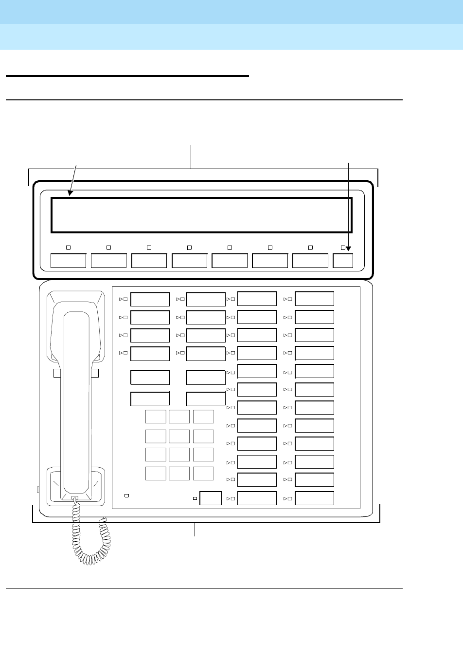
DEFINITYEnterpriseCommunicationsServerandSystem75andSystem85
Terminals and Adjuncts Reference
555-015-201 Issue 11
December 1999
Adjuncts
20-5Digital Display Modules
20
Digital Display Modules
Figure 20-2. The D401A Digital Display Module Mounted on a 7434D Voice Terminal
123
456
789
ABC DEF
MNOJKLGHI
PRS TUV WXY
*
O#
Oper
Conference
Drop
Transfer
Hold
Message
Select
Ring
7434D Voice Terminal
D401A Digital Display Module
40 Character
Alphanumeric Display On/Off Switch
On/Off
a=OUTSIDECALL

DEFINITYEnterpriseCommunicationsServerandSystem75andSystem85
Terminals and Adjuncts Reference
555-015-201 Issue 11
December 1999
Adjuncts
20-6Digital Display Modules
20
The D401A and D401B Digital Display Modules add a large easy-to-read
40-character display to the top of the 7405D or 7434D voice terminal. The D401
provides a vacuum-fluorescent display, which is significantly brighter than LCD
displays and visible from any angle. It provides prompt retrieval of Leave Word
Calling or Message Center messages, can identify incoming calls, both names
and number, and perform other functions.
Applications
The Digital Display Module can be used with the DEFINITY Communications
System Generic 1, Generic 2, and Generic 3, the DEFINITY ECS, System 75, and
System 85. It is used with the 7405D and 7434D voice terminals. It is particularly
useful for receptionists and executives.
Physical Description
Features
Automatic Displays
The D401A/B Digital Display Module automatically provides a visual display of the
following call-related information:
■Calling and called party identification
■Calling and called number
■Call coverage status
Auxiliary Displays
In its various auxiliary modes, the Digital Display Module also provides other
services:
■Time and date display
■Elapsed time on calls
■Message retrieval
■Display of stored abbreviated dialing numbers
■Access to Integrated Directory (except on System 85 or a
DEFINITY G2)
Display
A vacuum-fluorescent 40-character alphanumeric display that presents numerical
digits, uppercase and lowercase letters, and punctuation marks.

DEFINITYEnterpriseCommunicationsServerandSystem75andSystem85
Terminals and Adjuncts Reference
555-015-201 Issue 11
December 1999
Adjuncts
20-7Digital Display Modules
20
On/Off Switch
The On/Off switch turns the module on and off. The associated green status light
goes on when the module is on and is dark when the module is off.
Assignable Function Buttons
Seven additional buttons with associated green status lights. The system
manager assigns these buttons to display the control functions.
Display Functions
The following display functions are available on buttons (the actual labeling on
some buttons is shortened). If more than seven buttons are required, the
additional buttons may be assigned on the associated voice terminal.
■Normal Mode — used to place the display in the Normal mode, in which
the display provides call-related information automatically.
■Inspect Mode — used to place the display in the Inspect mode to permit
the user to see caller identification on an incoming or held call while active
on another call.
■Message Retrieval — used to place the display in the Message Retrieval
mode, in which the user can retrieve messages for the voice terminal on
which the module is mounted
■Coverage Message Retrieval — used to place the display in the
Coverage Message Retrieval mode, in which coverage agents can retrieve
messages for other terminals.
■Next — used in Message Retrieval mode to step from one message to the
next; also used in the Integrated Directory feature to display the next name
(except on System 85 or a DEFINITY G2).
■Delete Message — used in Message Retrieval mode to delete messages.
■Make Call — used in Message Retrieval mode to automatically initiate a
call to the caller identified by the last displayed message (for internal calls
only); also used to automatically call internal extension numbers displayed
by the Integrated Directory feature (except on System 85 or a DEFINITY
G2).
■Integrated Directory (except on System 85 or a DEFINITY G2) —used to
place the display in the Integrated Directory mode, in which the user can
search the system directory by entering the desired name with the dial pad,
and names with their corresponding extension numbers will be displayed.

DEFINITYEnterpriseCommunicationsServerandSystem75andSystem85
Terminals and Adjuncts Reference
555-015-201 Issue 11
December 1999
Adjuncts
20-8Digital Display Modules
20
■Stored Number — used to enable inspection of numbers stored in
Abbreviated Dialing (AD) lists or on individual AD buttons, or stored by the
Last Number Dialed feature. On System 85, this function is available on
some versions of R2V3 and R2V4, and G2.
■Timer — used to start or stop the elapsed timer function on the display
module; displays hours, minutes, and seconds.
■Date/Time — used to place the display in the Time of Day and Date mode
which initiates a display of the current time of day and the date.
Other Physical Features
Mounting Options
The Digital Display Module is mounted to the back of the associated voice
terminal at an angle that allows it to be easily used.
Color Options
The Digital Display Module is black or misty cream.
Power
The Digital Display Module requires auxiliary power from an external source. The
Adjunct Power section earlier in this manual lists the recommended power
supplies for the module alone or in combination with other adjuncts.
Considerations
A Digital Display Module and a Call Coverage Module
cannot
be mounted on the
same voice terminal simultaneously. The voice terminal
cannot
be wall mounted if
equipped with the Digital Display Module.
Digital Display Module PECs
The D401A Digital Display Module can be ordered with the following PECs:
■D401A Digital Display Module — PEC: 31742
■D401B Digital Display Module
(Black) PEC: 31742-003
(Misty cream) PEC: 31742-215
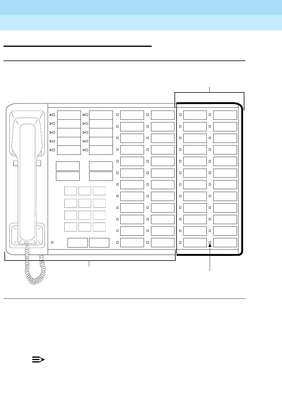
DEFINITYEnterpriseCommunicationsServerandSystem75andSystem85
Terminals and Adjuncts Reference
555-015-201 Issue 11
December 1999
Adjuncts
20-9Function Key Modules
20
Function Key Modules
Figure 20-3. The F201 or F401A Function Key Module Mounted on a 7405D Voice
Terminal
The Function Key Module greatly extends the feature access capability of the
voice terminal where it is used. The module provides 24 buttons that can be
assigned only to features. The F201A Function Key Module and the F401A
Function Key Module are identical in appearance, operation, and function.
NOTE:
Both the F201A and F401A function key modules have been manufacture
discontinued.
123
456
789
ABC DEF
MNOJKLGHI
PRS TUV WXY
*
O#
Oper
Conference
Drop
Transfer
Hold
Message
Disconnect
Recall
7405 Voice Terminal
Function Key Module
Status Light

DEFINITYEnterpriseCommunicationsServerandSystem75andSystem85
Terminals and Adjuncts Reference
555-015-201 Issue 11
December 1999
Adjuncts
20-10Function Key Modules
20
Applications
The Function Key Module can be used with the DEFINITY Communications
System Generic 1, Generic 2, and Generic 3, the DEFINITY ECS, System 75, and
System 85. The F201A is used with the 7205H multi-appearance hybrid voice
terminal (System 85 and the DEFINITY G2 only), while the F401A is used with the
7405D digital terminal.
Physical Description
Features
Feature buttons
The module provides 24 buttons that can only be assigned features. Each button
has a square green status light.
Other Physical Features
Mounting Options
As Figure 20-3 shows, the module attaches to the right side of the voice terminal,
adjacent to the terminal’s two columns of feature buttons. If a Digital Terminal
Data Module is also installed, it must be mounted on the right side of the Function
Key Module.
Color Options
The Function Key Module is silver.
Power
The F201A Function Key Module draws its required power from the system switch
through the 7205H voice terminal to which it is attached; no auxiliary power is
required. However, when an F401A module is used with a 7405D digital terminal,
auxiliary power must be fed through the terminal’s line cord from one of the
sourceslistedintheAdjunct Power section earlier in this manual.
Considerations
Either a Digital Terminal Data Module, a Call Coverage Module, or a Digital
Display Module can be mounted on the same terminal with a Function Key
Module.

DEFINITYEnterpriseCommunicationsServerandSystem75andSystem85
Terminals and Adjuncts Reference
555-015-201 Issue 11
December 1999
Adjuncts
20-11Function Key Modules
20
Digital Terminal Data Module PEC Codes
The F201A and F401A Function Key Modules were ordered using the following
PECs:
■F401A Function Key Module — PEC: 31744
■F201A Function Key Module — PEC: 31721
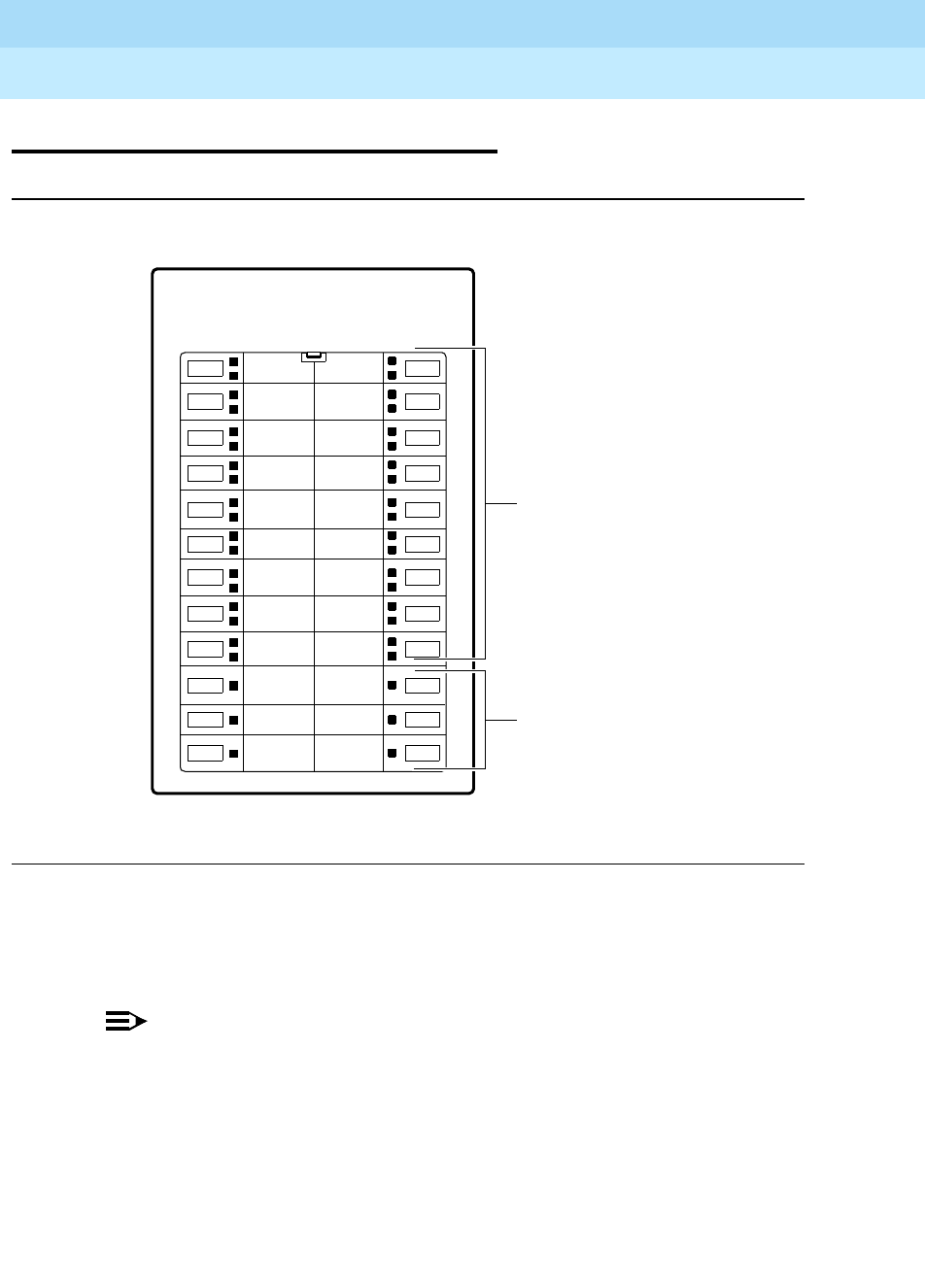
DEFINITYEnterpriseCommunicationsServerandSystem75andSystem85
Terminals and Adjuncts Reference
555-015-201 Issue 11
December 1999
Adjuncts
20-12The 801A Expansion Module
20
The 801A Expansion Module
Figure 20-4. The 801A Expansion Module
The 801A Expansion Module is an optional device which can be connected to an
8434DX (8434D02A) voice terminal to extend the number of call appearance and
feature buttons available on the voice terminal.
NOTE:
This expansion module can be connected ONLY to an 8434DX model
connected to a DEFINITY G3V3.3 (or later). The 8434DX has an Ex Mod
jack (labeled “EX MOD”) to which the 801A can be connected. Before
installing the expansion module to an 8434DX, make sure that the set is
labeled “8434DX,” has the “EX MOD” jack on the bottom of the set, and is
connected to a DEFINITY G3V3.3 (or later).
801A
18 Dual LED
call appearance/
feature buttons
6 Feature buttons,
each with a
green light

DEFINITYEnterpriseCommunicationsServerandSystem75andSystem85
Terminals and Adjuncts Reference
555-015-201 Issue 11
December 1999
Adjuncts
20-13The 801A Expansion Module
20
Applications
The 801A Expansion Module can be connected only to an 8434DX voice terminal.
Physical Description
Features
Buttons
The expansion module has 24 buttons arranged in two columns.
■The top 18 buttons (that is, the top nine buttons in each column) have a red
and a green light next to them. These buttons can be used for call
appearances or features.
■The bottom six buttons (that is, the last three buttons in each column) have
a single green status light next to them. These buttons can be used for
features only.
Other Physical Features
Mounting
The 801A Expansion Module is connected to an 8434DX voice terminal with a
D6AP-87 cord. This cord is plugged into the EX MOD jack on the voice terminal
and then plugged into the TELSET jack on the expansion module.
Color Options
The Expansion Module is available in black or in white.
Power
The expansion module requires auxiliary power.
■Suitable stand-alone power supplies include the 1151A1 and 1151A2 with
Battery Holdover, and the MSP-1.
NOTE:
Since the 8434DX voice terminal requires auxiliary power, it is likely that an
MSP-1 will already be connected to the 8434DX terminal.
■Suitable bulk power supplies are the 1145A and the 1145B1.
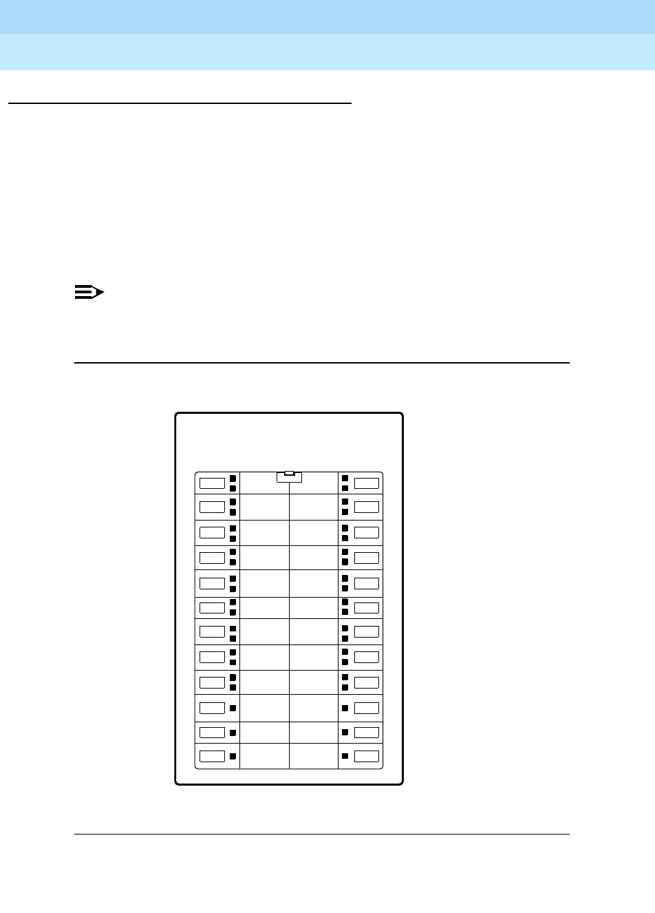
DEFINITYEnterpriseCommunicationsServerandSystem75andSystem85
Terminals and Adjuncts Reference
555-015-201 Issue 11
December 1999
Adjuncts
20-14The 801A Expansion Module
20
Administering the 801A Expansion Module
The 8434DX with an attached expansion module can be used ONLY with systems
such as a DEFINITY G3V3.3 or later that allow native support. That is, the
8434DX MUST BE ADMINISTERED AS ITSELF, not aliased as any other type of
voice terminal.
On the first station administration screen of the 8434DX, put a “Y” (for Yes) next to
the “Expansion Module?” entry. On the last page of the administration screens,
type the telephone or extension numbers or feature names next to the appropriate
expansion module buttons in the following sequence.
NOTE:
You can place ONLY features on expansion module Buttons #10, 11, 12, 22,
23, and 24. You CANNOT administer these buttons as call appearances.
Figure 20-5. Button Numbering for Administering the
801A Expansion Module
801A
1
2
3
4
13
15
16
175
6
7
8
18
19
20
9
10
11
12
21
22
23
24
14

DEFINITYEnterpriseCommunicationsServerandSystem75andSystem85
Terminals and Adjuncts Reference
555-015-201 Issue 11
December 1999
Adjuncts
20-15The 801A Expansion Module
20
801A Expansion Module PECs
The 801A Expansion Module can be ordered with the following PECs:
■Black ZE801A-003 Expansion Module
(Black) PEC: 32300, Comcode: 106702921
(White) PEC: 32301, Comcode: 106702764
■2-foot D6AP-87 line cord
Comcode: 105644744
Additional Documents
The following document is shipped with the expansion module. Additional copies
are available from the BCS Publications Center for Lucent Technologies:
■
801A Expansion Module Instruction Manual
, 555-015-136
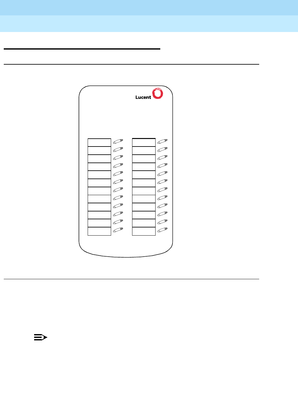
DEFINITYEnterpriseCommunicationsServerandSystem75andSystem85
Terminals and Adjuncts Reference
555-015-201 Issue 11
December 1999
Adjuncts
20-16The XM24 Expansion Module
20
The XM24 Expansion Module
Figure 20-6. The XM24 Expansion Module
The XM24 Expansion Module is an optional device which can be connected to a
6416D+, 6416D+M, 6424D+, 6424D+M, or CALLMASTER V telephone to extend
the number of call appearance and feature buttons available on each of these
telephones.
NOTE:
Since the newer modular 6416D+M and 6424D+M have been built with a
slightly different angle than the non-modular 6416D+ and 6424D+
telephones, there are also two versions of the XM24 Expansion Module
■The original XM24 meant for use with the 6416D+ and 6424D+
(White = PEC: 33074, Comcode: 108023235
Gray = PEC: 33076, Comcode: 108023243)
XM24

DEFINITYEnterpriseCommunicationsServerandSystem75andSystem85
Terminals and Adjuncts Reference
555-015-201 Issue 11
December 1999
Adjuncts
20-17The XM24 Expansion Module
20
■The XM24 with a different angle, meant for the modular 6416D+M,
6424D+M, and CALLMASTER V
(White = PEC: 33072, Comcode: 108554503
Gray = PEC: 33071, Comcode: 108445511)
Applications
The XM24 Expansion Module can be connected only to a 6416D+, 6416D+M,
6424D+, 6424D+M, or a CALLMASTER V telephone. These telephones have an
“XM24” jack on the bottom of the set in order to allow connection with the
expansion module.
Physical Description
Features
Buttons
The XM24 Expansion Module has 24 buttons arranged in two columns. Each of
these buttons has a red and green light next to it. These buttons can be used for
call appearances or features.
Other Physical Features
Mounting
The XM24 Expansion Module is connected to a 6416D+, 6416D+M, 6424D+, a
6424D+M, or CALLMASTER V telephone with a D6AP-87 cord. This cord is
plugged into the XM24 jack on the voice terminal and then plugged into the jack
on the expansion module.
Color Options
This expansion module is available in gray or in white.
Power
This expansion module requires auxiliary power.
■Suitable stand-alone power supplies include the 1151A1and the 1151A2
with Battery Holdover, and the MSP-1.
■Suitable bulk power supplies are the 1145A and the 1145B1.
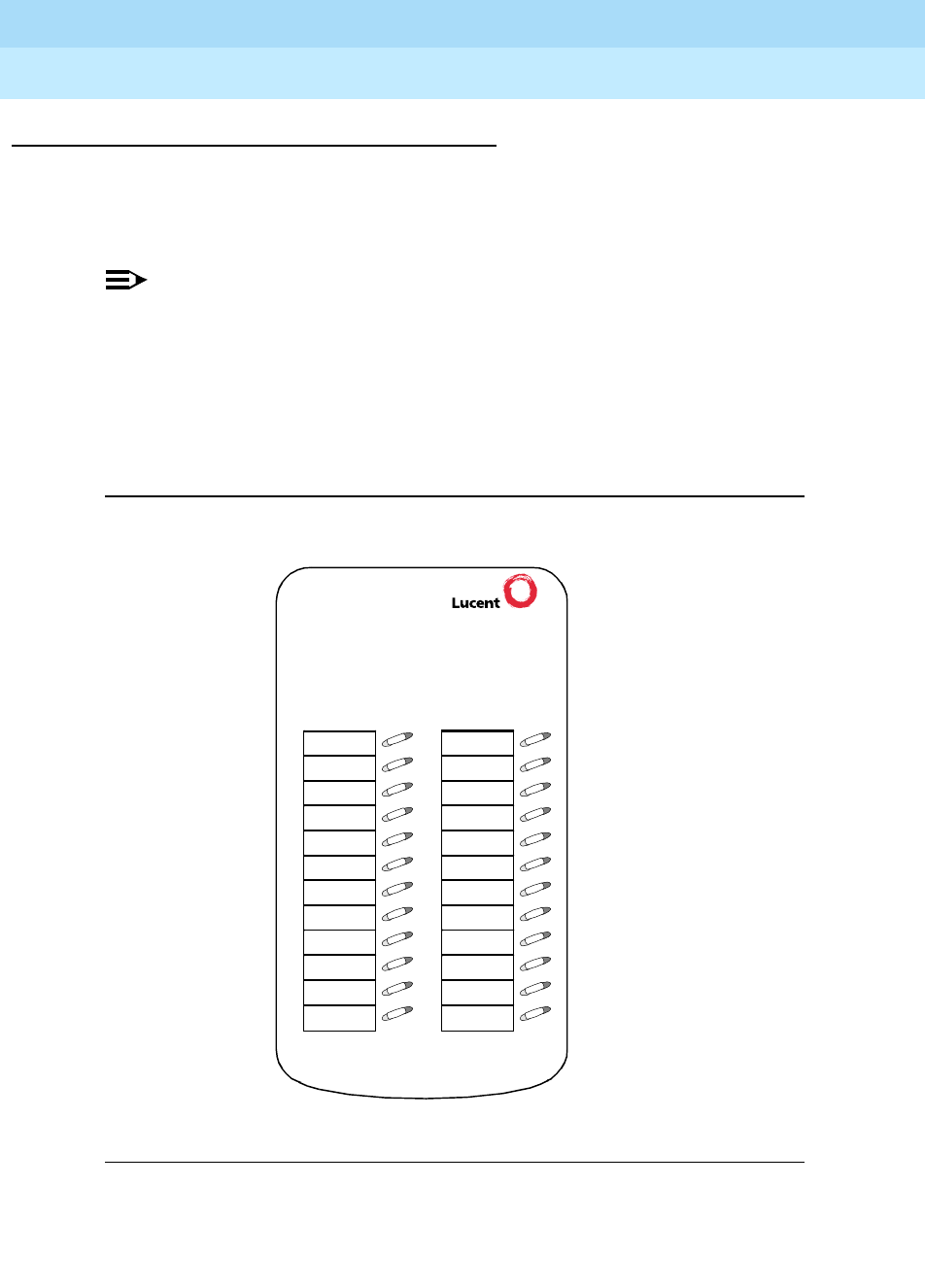
DEFINITYEnterpriseCommunicationsServerandSystem75andSystem85
Terminals and Adjuncts Reference
555-015-201 Issue 11
December 1999
Adjuncts
20-18The XM24 Expansion Module
20
Administering the XM24 Expansion Module
The 6416D+ or 6424D+ with connected expansion module are administered as
itself only on DEFINITY ECS Release 6.1 and later. These telephones with or
without an expansion module cannot be aliased as any other telephone.
NOTE:
The 6416D+M and CALLMASTER V are administered as a 6416D+; a
6424D+M is administered as a 6424D+.
On the first station administration screen of the 6416D+ or 6424D+, put a “Y” (for
Yes) next to the “Expansion Module?” entry. On the last page of the administration
screens, type the telephone or extension numbers or feature names next to the
appropriate expansion module buttons in the following sequence.
Figure 20-7. Button Numbering for Administering the
XM24 Expansion Module
XM24
1
2
3
4
5
6
7
8
9
10
11
12
13
14
15
16
17
18
19
20
21
22
23
24

DEFINITYEnterpriseCommunicationsServerandSystem75andSystem85
Terminals and Adjuncts Reference
555-015-201 Issue 11
December 1999
Adjuncts
20-19The XM24 Expansion Module
20
XM24 Expansion Module PECs and Comcodes
The XM24 Expansion Module can be ordered with the following PECs and
Comcodes:
■The XM24 that can be used with the original non-modular 6416D+ and
6424D+:
XM24-264 (White) Expansion Module
PEC: 33074, Comcode: 108023235
XM24-264 (White) Expansion Module with 1151A Power Supply
PEC: 33073
Comcode for XM24 expansion module: 108023235
Comcode for 1151A power supply: 107785693
OR
XM24-323 (Gray) Expansion Module
PEC: 33076, Comcode: 108023243
XM24-323 (Gray) Expansion Module with 1151A Power Supply
PEC: 33075
Comcode for XM24 expansion module: 108023243
Comcode for 1151A power supply: 107785693
■The XM24 that can be used with the modular 6416D+M and 6424D+M:
XM24 (White) Expansion Module
PEC: 33072, Comcode: 108554503
OR
XM24 (Gray) Expansion Module
PEC: 33071, Comcode: 108544511
■2-foot D6AP-87 line cord
Comcode: 105644744
Additional Documents
The following document is shipped with the expansion module. Additional copies
are available from the BCS Publications Center for Lucent Technologies:
■
XM24 Expansion Module Instruction Manual
, 555-015-115
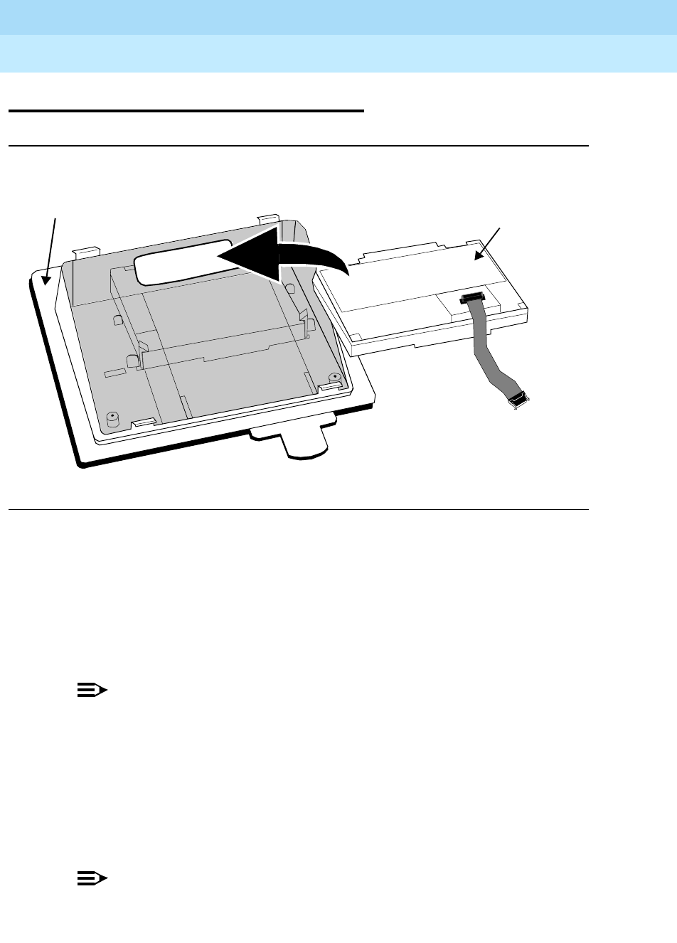
DEFINITYEnterpriseCommunicationsServerandSystem75andSystem85
Terminals and Adjuncts Reference
555-015-201 Issue 11
December 1999
Adjuncts
20-20The 100A Tip/Ring Module
20
The 100A Tip/Ring Module
Figure 20-8. The 100ATip/Ring Module Being Installed in the Desktop Stand
of a 6416D+ or 6424D+ Telephone
The Tip/Ring module can be installed in the desktop stand of the Modular
6416D+M (6416D02A) and 6424D+M (6424D02A) telephones to provide
increased set functionality. Through a 6-position RJ11-type jack, the Tip/Ring
module allows connection between these two 6400 Series telephone models and
such analog adjuncts as answering machines, fax machines, modems, analog
speakerphones, and TDD machines commonly used by the hearing impaired.
NOTE:
The Tip/Ring module is capable of supporting modem communication rates
up to
33.6 Kbps. However, the maximum modem communication rate cannot
be guaranteed because it is limited by the quality of the end-to-end channel.
Also note that only DTMF (Dual Tone Multi-Frequency) dialing is supported
by the Tip/Ring module.
This Tip/Ring module has been specially designed so that the voice quality of the
analog adjunct connected to the module is equivalent to the performance of the
analog adjunct when it is connected to an analog port on a DEFINITY switch.
NOTE:
This is true only for DEFINITY switches which use United States
transmission levels.
Tip/Ring Module
Back of 6416D+M or 6424D+M
Telephone Desktop Stand

DEFINITYEnterpriseCommunicationsServerandSystem75andSystem85
Terminals and Adjuncts Reference
555-015-201 Issue 11
December 1999
Adjuncts
20-21The 100A Tip/Ring Module
20
The module also has a special detector which senses if the analog adjunct is
on-hook or off-hook, and the module, therefore, is able to disconnect the analog
adjunct at the end of a call. However, whether the analog adjunct responds to a
request to hang up depends on the design of the analog adjunct.
Applications
The Tip/Ring module can ONLY be used with the Modular 6416D+M and
6424D+M telephones; that is, the telephone desktop stand must have a module
opening in which the module can be installed. Once installed, the module has an
analog adjunct jack to which the analog adjunct equipment can be connected.
The 6400 Series telephones have been developed to be used with the DEFINITY
ProLogix system, but can also be used with the larger DEFINITY ECS
Release 6.1 and later. These telephones, and thus the attached Tip/Ring module,
CANNOTbeusedwithanyDEFINITYreleasepriortoRelease6.1.For
information on how the Tip/Ring module can be used with DEFINITY releases
after Release 6.1, see “Considerations” below.
For more information about the 6400 Series telephones, see the material included
in the 6400 Series Telephones section earlier in this manual.
Considerations
The manner in which the telephone and the analog adjunct interact depends on
the switch release to which your telephone is connected. (Your system manager
can give you more information about the switch release.)
■On DEFINITY Enterprise Communications Server (ECS) releases prior to
Release 8.1, going back to Release 6.1, the analog adjunct shares the
telephone line with the voice terminal. Therefore, while the telephone is
being used, you
cannot
use the analog adjunct at the same time, or vice
versa.
■On the DEFINITY ECS Release 8.1 and later, the telephone and the
analog adjunct can be assigned separate telephone lines, and thus the
voice terminal and analog adjunct can be used
simultaneously
.
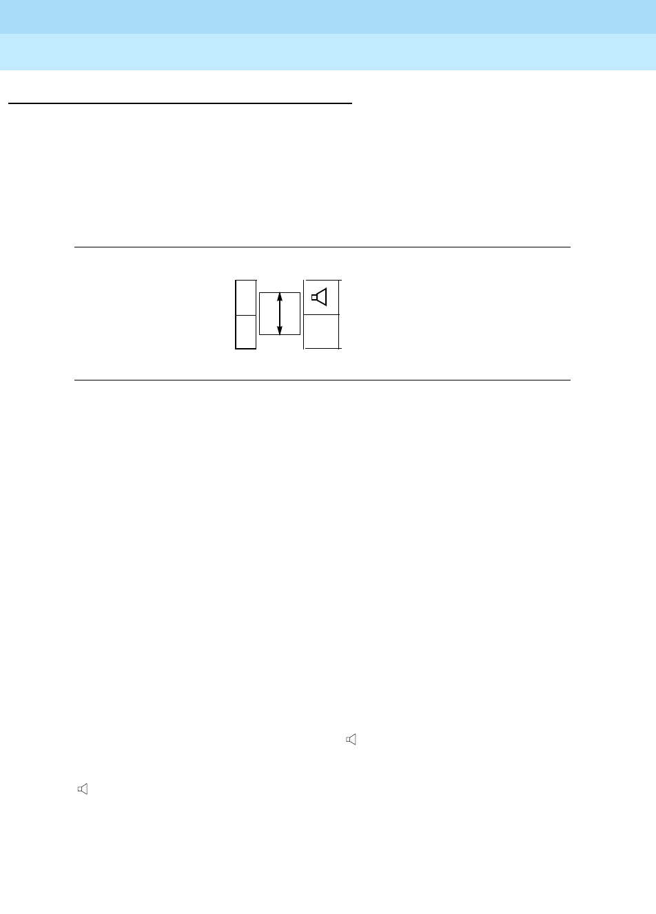
DEFINITYEnterpriseCommunicationsServerandSystem75andSystem85
Terminals and Adjuncts Reference
555-015-201 Issue 11
December 1999
Adjuncts
20-22The 100A Tip/Ring Module
20
Physical Description
Features
The Tip/Ring Module Option Switches
On the back of the 100A Tip/Ring module are two option switches shown below.
Figure 20-9. The Two Option Switches on the Tip/Ring Module
TheOptionSwitchontheLeft,Labeled1and2—Theoptionswitchontheleft
allows you to choose the line that the connected analog adjunct will use.
— WhentheOptionswitchontheleftissetto1, the telephone and the Analog
adjunct
share the same line
. Therefore, only one device, the telephone
handset OR the telephone built-in speakerphone OR the Analog adjunct
can transmit on the same line at one time.
If the Tip/Ring device is installed on a 6416D+M or 6424D+M telephone
connected to a DEFINITY switch prior to Release 8.1, you MUST
use
Setting 1; that is, you CANNOT use Setting 2.
— WhentheOptionswitchontheleftissetto2, you can use a second line for
transmission on the analog adjunct, a line that is independent of the
telephone. When the second line is used, the telephone and the analog
adjunct can use independent lines
simultaneously
.
If the Tip/Ring module is installed on a 6416D+ or 6424D+ telephone
connected to a DEFINITY switch Release 8.1 or later, you can set the
switchonthelefttoSetting1or 2.
The Option Switch on the Right, Labeled and FAX —If you selected
Setting 1 on the left option switch (that is, the telephone and the analog adjunct
use the same line), you MUST ALSO SET the option switch on the right, labeled
and FAX. This switch allows you to choose whether the analog adjunct, when
active, will be interrupted when you pick up the handset or turn on the built-in
speakerphone.
2
1
FAX

DEFINITYEnterpriseCommunicationsServerandSystem75andSystem85
Terminals and Adjuncts Reference
555-015-201 Issue 11
December 1999
Adjuncts
20-23The 100A Tip/Ring Module
20
Set the option switch on the right according to the analog device that is connected
with the telephone.
— The option means that the analog adjunct will be interrupted. Use this
option for adjunct speakerphones or answering machines. If an
attached speakerphone does not recognize a far end disconnect signal,
you may have to manually turn off the speakerphone.
—The
FAX option does not interrupt the analog adjunct. Use this option for
fax machines and modems.
NOTE:
The system manager may choose to administer a feature button on the
telephone to provide you visible indication of the status of the second line
used on Setting 2. Then, whenever the analog adjunct is active on the
second line, the green light next to the button goes on.
Switch translation changes may be needed if the Tip/Ring module is
optioned for Setting 2. See your system manager.
Telephone Display Indications
The telephone display provides visible indication whether the module has power.
A“
+” appears in the upper right of the time/date display if there IS power to the
module. A “-” appears on the time/date display if the module does NOT have
power.
Other Physical Features
Required Cord
Either a D8W or a D2R line cord can be used to attach an auxiliary power supply
to the Line jack on the telephone. If you have only a 2-wire line cord, replace it with
the 8-wire cord that comes with the power supply.The auxiliary power supply can
then be connected to the wall jack.
Mounting
The 100A Tip/Ring module is connected to a 6416D+M or a 6424D+M telephone
with a ribbon cable on the back of the module. This ribbon cable is then connected
to the module jack on the back of the desktop stand.
Color Options
The Tip/Ring module is available only in light gray.
DEFINITYEnterpriseCommunicationsServerandSystem75andSystem85
Terminals and Adjuncts Reference
555-015-201 Issue 11
December 1999
Adjuncts
20-24The 100A Tip/Ring Module
20
Power
The Tip/Ring module will work ONLY if it has auxiliary power. When the auxiliary
power source is turned on, the Tip/Ring module will automatically power up.
Suggested power supplies include:
■Suitable stand-alone power supplies include the 1151A1 and the 1151A2
with Battery Holdover.
■Suitable bulk power supplies are the 1145A and the 1145B1.
NOTE:
If there is a power outage and the auxiliary power source shuts off, the
telephone will continue to work, but the Tip/Ring module will NOT function.
Administering the Tip/Ring Module
The 6416D+M and 6424D+M telephones are administered as a 6416D+ or
6424D+; however, they MUST BE connected to a DEFINITY ECS Release 6.1 (or
later). In Native Mode the modular 6416D+M and 6424D+M telephones are
administered through a digital line circuit card with a line number (with the usual
three call appearances) assigned to the I-1 Channel. If the 6416D+M or 6424D+M
is connected to a DEFINITY ECS Release 8.1 or later, a second line number can
be administered through the same digital line card on the I-2 Channel, but this line
number can only be used for analog adjuncts connected to the Tip/Ring module.
This analog adjunct is assigned a private number, but can be used only for placing
or terminating a call. It cannot be used for any other analog functions such as
transferring a call or setting up a conference call. If a second line on the telephone
is administered on the I-2-Channel (for analog equipment), type “analog” in the
Data Option field on the administration screen.
On the first station administration screen of the 6416D+ or 6424D+, put a “Y” (for
Yes) next to the “Tip/Ring Module?” entry.
100A Tip/Ring Module PECs and Comcodes
The 100A Tip/Ring Module can be ordered with the following PECs and
Comcodes:
■100A-266 Tip/Ring Module
(White) PEC: 3305-TR1, Comcode: 108332446
100A-266Tip/Ring Module with 1151A Power Supply
PEC: 3305-TRP
■D2R-87 cord
Comcode: 105001861

DEFINITYEnterpriseCommunicationsServerandSystem75andSystem85
Terminals and Adjuncts Reference
555-015-201 Issue 11
December 1999
Adjuncts
20-25The 100A Tip/Ring Module
20
Additional Documents
The following document is shipped with the Tip/Ring module. Additional copies
are available from the BCS Publications Center for Lucent Technologies:
■
The Tip/Ring Interface Module Installation and User Instructions,
555-233-707.
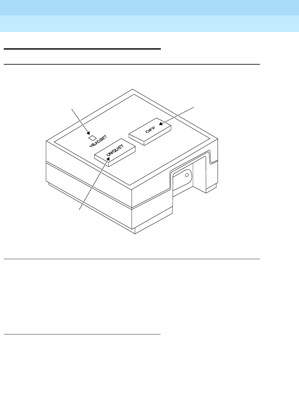
DEFINITYEnterpriseCommunicationsServerandSystem75andSystem85
Terminals and Adjuncts Reference
555-015-201 Issue 11
December 1999
Adjuncts
20-26Headset Adapters
20
Headset Adapters
Figure 20-10. The 500A Headset Adapter
Two adapters are available to allow the use of standard headsets with voice
terminals connected to the DEFINITY Communications System Generic 1,
Generic 2, and Generic 3, the DEFINITY Enterprise Communications Server
(ECS), System 75, and System 85. The 500A and the 502A Headset Adapters are
identical in appearance, operation, and function but different in internal circuitry.
Applications
The 500A and 502A headset adapters can be used with the DEFINITY G1,G2,
and G3, the DEFINITY ECS, System 75, and System 85. The 500A adapter can
be used with single-line Models 6402 and 6402D, 7103A, 7102A, and 7102A Plus
and multi-appearance Models 6408, 6416D+, 6424D+, 7203H, 7205H, 7403D,
7405D, 7406D, 7406BIS, 7406 Plus, Enhanced 7407D, 7407 Plus, 7410D, 7410
Plus, 7434D, 7444, 8403, 8405, 8410, 8411, 8434, 8434DX, and 8102 voice
terminals/telephones and the 6508, 7505, 7506, 7507, 8503T, 8510T, and 8520T
ISDN terminals. The 502A adapter is intended for use with multi-appearance
Models 7303S and 7305S voice terminals only.
Headset
Light
On/Quiet
Switch
Off Switch

DEFINITYEnterpriseCommunicationsServerandSystem75andSystem85
Terminals and Adjuncts Reference
555-015-201 Issue 11
December 1999
Adjuncts
20-27Headset Adapters
20
Physical Description
Features
On/Quiet Switch
This dual-purpose switch is used to:
■Turn on the adapter connecting the headset to the voice terminal. Pressing
the On switch is equivalent to going off-hook with the handset.
■Disable the transmitter of the headset temporarily for privacy.
Off Switch
■Turns off the adapter and disconnects the headset.
■Pressing the Off switch is equivalent to going on-hook with the handset.
Headset Jack
Used to connect the double phone plug of the headset.
Headset Light
Indicates when the headset is active.
Other Physical Features
Cords
A modular cord is needed for connecting the headset adapter to the associated
voice terminal. The cord carries audio signals between the adapter and the
terminal and power for the adapter.
Mounting Options
The headset adapter is mounted close to its associated voice terminal.
Color Options
The 500A headset adapter is silver while the 502A is black.
Power
The 500A Headset Adapter requires either AC or DC auxiliary power from one of
the sources listed in the Adjunct Power section earlier in this manual. Power,
from the source supply, is applied by way of the voice terminal’s mounting cord
and the adapter’s connecting cord. The 502A draws its power from the system
switch through the associated voice terminal.

DEFINITYEnterpriseCommunicationsServerandSystem75andSystem85
Terminals and Adjuncts Reference
555-015-201 Issue 11
December 1999
Adjuncts
20-28Headset Adapters
20
Considerations
The use of a headset provides hands-free terminal operation with more privacy
than a speakerphone. A headset is especially convenient for users who must
frequently type or look up information during calls.
NOTE:
A speakerphone and a headset adapter cannot be connected to the same
voice terminal simultaneously.
Typical Headsets
The following are typical headsets (consisting of either modular or plug prong
base units and choice of headpieces) that can be connected to the 500A, the new
500A1, and the 502A adapters:
■Plug Prong Base Unit
PEC: 3122-010
Black
NOTE:
Plug Prong Base Units require a headset adapter.
■Modular Base Unit
PEC: 3122-020
Black/modular
■Starset Headpiece
PEC: 3122-030
Black/behind the ear
■Supra Headpiece
PEC: 3122-040
Black/over the ear
■Mirage Headpiece
PEC: 3122-050
Black/behind the ear
■Supra Noise-Cancelling Headpiece
PEC: 3122-060
Black/over the ear
500A and 502A Headset Adapter PECs
The 500A and 502A headset adapters can be ordered using the following PECs:
■500A Headset Adapter — PEC: 3122-001
■502A Headset Adapter — PEC: 3164-HFA
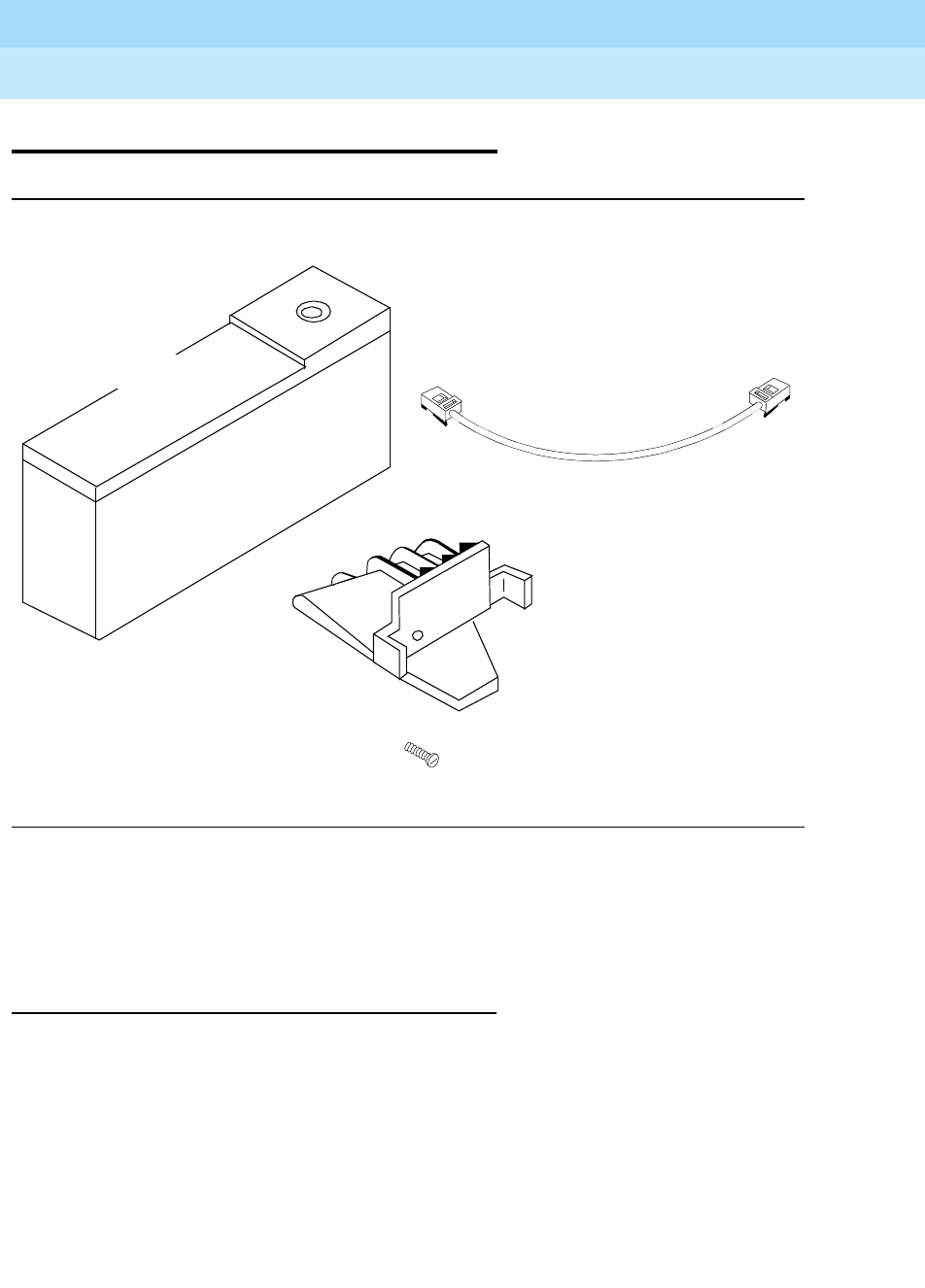
DEFINITYEnterpriseCommunicationsServerandSystem75andSystem85
Terminals and Adjuncts Reference
555-015-201 Issue 11
December 1999
Adjuncts
20-29The Z34A Message Waiting Indicator
20
The Z34A Message Waiting Indicator
Figure 20-11. The Z34A Message Waiting Indicator
The Z34A Message Waiting Indicator is an adjunct that can be attached to analog
voice terminals to allow these terminals to take advantage of the Leave Word
Calling feature or message retrieval via AUDIX.
Applications
The Z34A Message Waiting Indicator can be used with the DEFINITY
Communications System Generic 1, Generic 2, and Generic 3, the
DEFINITY ECS, System 75, and System 85. It is used with the Model 2500 voice
terminal.
Screw
500/2500-Type Telephone
Mounting Bracket
D4BU 1-Foot Line Cord
Z34A Message
Waiting Light

DEFINITYEnterpriseCommunicationsServerandSystem75andSystem85
Terminals and Adjuncts Reference
555-015-201 Issue 11
December 1999
Adjuncts
20-30The Z34A Message Waiting Indicator
20
Physical Description
Features
Light
The Z34A contains a red light that flashes automatically when a message has
been left for the terminal user.
Other Physical Features
Mounting Options
The Z34A mounts on the right side of the voice terminal and is electrically
connected between the terminal’s line jack and the wall jack.
Color Options
The Z34A is available in ultra light gray only.
Power
The Z34A Message Waiting Indicator receives its power from the same tip and
ring leads as its associated voice terminal receives its power.
Message Waiting Indicator PECs
The Z34A can be ordered using the following PEC:
■Z34A Message Waiting Indicator — PEC: 3152-004A
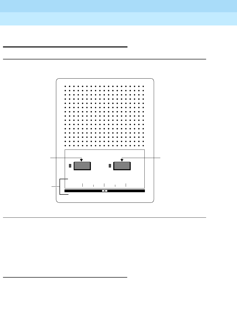
DEFINITYEnterpriseCommunicationsServerandSystem75andSystem85
Terminals and Adjuncts Reference
555-015-201 Issue 11
December 1999
Adjuncts
20-31The 4A, S101A, and S102A Speakerphones
20
The 4A, S101A, and S102A
Speakerphones
Figure 20-12. The S101A and S102A Speakerphones
Speakerphones are available for providing total voice terminal operation without
the use of the handset. Turning on the speakerphone is equivalent to lifting the
voice terminal handset when placing or answering a call. Turning off the
speakerphone is equivalent to hanging up the handset. The microphone switch
temporarily cuts off transmission to the distant party during a call.
Applications
The speakerphones can be used with the DEFINITY Communications System
Generic 1, Generic 2, and Generic 3, the DEFINITY ECS, System 75, and System
85. The S101A Speakerphone can be used with the single-line Models 7103A and
7102A and multi-appearance Models 7203H, 7205H, 7403D, 7405D, 7406D,
7406BIS, 7406 Plus, Enhanced 7407D, 7407 Plus, 7410D, 7410 Plus, 7434D,
7444, 8403, 8405, 8410, 8411, 8434, 8434DX, and 8102 voice
terminals/telephones, and the 6508, 7505, 7506, 7507, 8503T, 8510T, and 8520T
Speakerphone
Volume
Speakerphone
Microphone
Low
On/Off
High
On/Off
On/Off Button Microphone
On/Off Button
Volume Control

DEFINITYEnterpriseCommunicationsServerandSystem75andSystem85
Terminals and Adjuncts Reference
555-015-201 Issue 11
December 1999
Adjuncts
20-32The 4A, S101A, and S102A Speakerphones
20
ISDN terminals. The S102A is intended for use with multi-appearance Models
7303S and 7305S voice terminals only. The 4A speakerphone is used only with
the basic 2500-series terminals and METs on an “in place” basis.
Physical Description
S101A and S102A Speakerphones Features
On/Off button for Speakerphone
There is a nonlocking On/Off button and adjacent green light for the
speakerphone.
On/Off button for Microphone
There is also a nonlocking On/Off button and adjacent green light for the
microphone.
Sliding volume control
The volume of the speaker is controlled by this slide switch.
Cord
A modular cord for connecting the speakerphone to the associated voice terminal;
the cord carries audio signals between the speakerphone and the terminal and
power for the speakerphone.
Color Options
The S101A and S102A speakerphones are silver.
4A Speakerphone Features
ON or QUIET button
This nonlocking button turns the speakerphone on (same as going off-hook). This
button is also used to place the speakerphone in a listen-only mode.
OFF button
This locking button turns the speakerphone off (same as going on-hook).
Vo l um e
The volume of the speaker is controlled by this knob.
Color Options
The 4A Speakerphone is available in avocado, black, white, beige, and ivory.

DEFINITYEnterpriseCommunicationsServerandSystem75andSystem85
Terminals and Adjuncts Reference
555-015-201 Issue 11
December 1999
Adjuncts
20-33The 4A, S101A, and S102A Speakerphones
20
Power
The S101A and S102A Speakerphones require either AC or DC auxiliary power
from one of the sources listed the Adjunct Power section earlier in this manual.
Power from the source supply is applied by way of the voice terminal’s mounting
cord and the speakerphone’s connecting cord. The S102A draws its power from
the system switch through the associated voice terminal; it does not require an
auxiliary power source.
The 4A Speakerphone requires auxiliary power from one of the sources listed in
the Adjunct Power section earlier in this manual. The power from the source
supply is applied to the loudspeaker set and the transmitter through an adapter or
connecting block provided with the 4A Speakerphone.
Considerations
A speakerphone and a headset adapter
cannot
be connected to the same voice
terminal simultaneously.
Speakerphone PECs
The speakerphones can be ordered by using the following PECs:
■S101A Speakerphone — PEC: 31711 (not orderable)
■S102A Speakerphone — PEC: 31730 (not orderable)
■4A Speakerphone
(Avocado) — PEC: 3120-02W-COL01
(Black) — PEC: 3120-02W-COL09
(White) — PEC: 3120-02W-COL10
(Beige) — PEC: 3120-02W-COL11
(Ivory) — PEC: 3120-02W-COL12
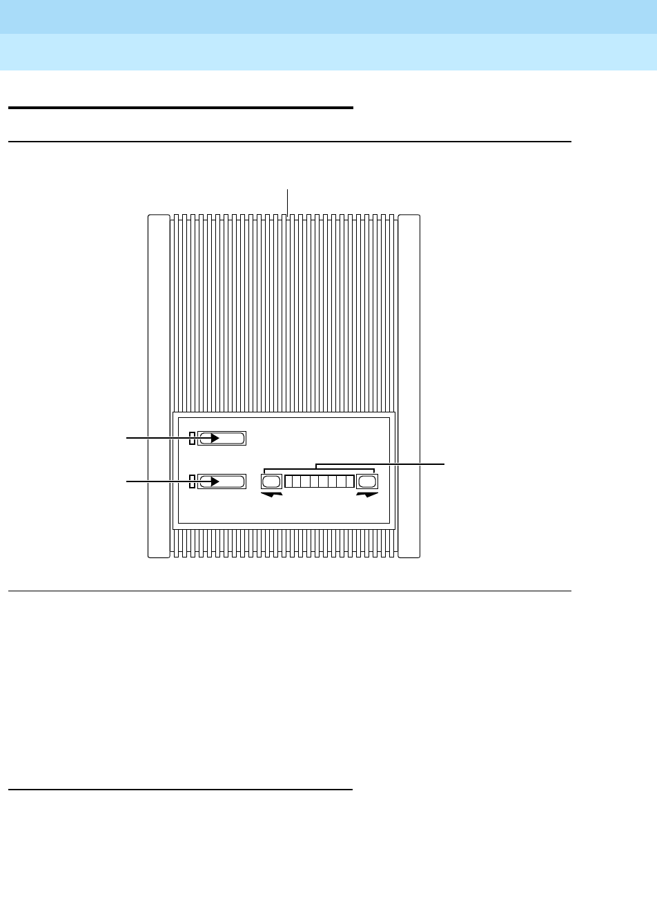
DEFINITYEnterpriseCommunicationsServerandSystem75andSystem85
Terminals and Adjuncts Reference
555-015-201 Issue 11
December 1999
Adjuncts
20-34The S201A and S202A Speakerphones
20
The S201A and S202A Speakerphones
Figure 20-13. The S201A and S202A Speakerphones
The S201A and S202A speakerphones are available for providing total voice
terminal operation without the use of the handset. Turning on the speakerphone is
equivalent to lifting the voice terminal handset when placing or answering a call.
Turning off the speakerphone is equivalent to hanging up the handset. The Mute
switch temporarily cuts off transmission to the distant party during a call. The
S201A and S202A speakerphones automatically adapt to room acoustics, thereby
dramatically improving the sound quality.
Applications
These speakerphones can be used with the DEFINITY Communications System
Generic 1, Generic 2, and Generic 3, the DEFINITY ECS, System 75, and System
85. The S201A Speakerphone can be used with the single-line Models 7103A,
7102A, and 7102 Plus and multi-appearance Models 7203H, 7205H, 7403D,
7405D, 7401 Plus, 7406D, 7406BIS, 7406Plus, Enhanced 7407, 7407 Plus,
7410D, 7410 Plus, 7434D, 7444, 8403, 8405, 8410, 8434, 8434DX, and 8102
Mute
Speakerphone
Volume
Volume
Speakerphone
Button
Mute Button
Reset Button
Indicator
Bar and Buttons

DEFINITYEnterpriseCommunicationsServerandSystem75andSystem85
Terminals and Adjuncts Reference
555-015-201 Issue 11
December 1999
Adjuncts
20-35The S201A and S202A Speakerphones
20
voice terminals/telephones, and the 7505, 7506, and 7507, 8503T, 8510T, and
8520T ISDN terminals. The S202A is intended for use with multi-appearance
Models 7303S and 7305S voice terminals only.
Physical Description
Features
Speakerphone button
This locking button turns the speakerphone on and off. When the green light is on,
the speakerphone is on.
Mute button
This nonlocking button and its red light are for the microphone. When the light is
on, the microphone is muted.
Volume control
The volume of the speaker is controlled by the volume buttons associated with the
arrows. The lights on the volume indicator bar shows the selected volume level.
Reset button
The RESET button automatically performs an acoustic test of the environment.
Other Physical Features
Cord
A modular cord connects the speakerphone to the associated voice terminal. This
cord carries audio signals between the speakerphone and the terminal and power
for the speakerphone.
Jack
A modular jack is located on the rear of the speakerphone.
Color Options
The S201A and S202A speakerphones can be misty cream or black.

DEFINITYEnterpriseCommunicationsServerandSystem75andSystem85
Terminals and Adjuncts Reference
555-015-201 Issue 11
December 1999
Adjuncts
20-36The S201A and S202A Speakerphones
20
Power
The S201A Speakerphone requires either AC or DC auxiliary power from one of
the sources listed in the Adjunct Power section earlier in this manual. Power from
the source supply is applied by way of the voice terminal’s mounting cord and the
speakerphone’s connecting cord. A 24 volt, 7.5 Va AC transformer with a 400 B2
adapter is packed with the S201A Speakerphone. The transformer may be
located up to 125 feet from the speakerphone. The S202A Speakerphone draws
power from the associated telephone.
!WARNING:
Do not use the 2102D wall transformer due to incorrect voltage.
Considerations
A speakerphone and a headset adapter
cannot
be connected to the same voice
terminal simultaneously.
S201A and S202A Speakerphone PECs
The speakerphones can be ordered by using the following PECs:
■S201A Speakerphone — PEC: 3152-007A
■S202A Speakerphone — PEC: 3152-008A
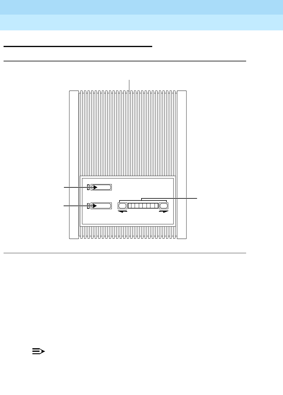
DEFINITYEnterpriseCommunicationsServerandSystem75andSystem85
Terminals and Adjuncts Reference
555-015-201 Issue 11
December 1999
Adjuncts
20-37The S203A Speakerphone
20
The S203A Speakerphone
Figure 20-14. The S203 Speakerphone
The S203A Speakerphone is an analog speakerphone with Auto-Answer and
Automatic Disconnect capabilities. The S203A can be used in conjunction with
any single-line analog set (an additional 267A2 bridging adapter is included for
this arrangement) or as a stand-alone unit. When it is used in a stand-alone
operation, the S203A provides no dialing functionality. When the Auto-Answer
feature is enabled, an incoming call will cause the S203A to automatically go
off-hook and emit a special tone that is heard by both the calling and called
parties. This tone indicates that the call has been automatically answered. The
S203A Speakerphone automatically adapts to room acoustics, thereby
dramatically improving the sound quality.
NOTE:
This speakerphone is available with a wall-mounting bracket.
Mute
Speakerphone
Volume
Volume
Indicator
Bar and
Buttons
Speakerphone
Button
Mute/Auto
Answer
Reset Button
Auto Answer
Button
DEFINITYEnterpriseCommunicationsServerandSystem75andSystem85
Terminals and Adjuncts Reference
555-015-201 Issue 11
December 1999
Adjuncts
20-38The S203A Speakerphone
20
Applications
The S203A Speakerphone can be used with the DEFINITY Communications
System Generic 1, Generic 2, and Generic 3, the DEFINITY ECS, System 75, and
System 85. Its Auto-Answer and Auto-Disconnect capabilities make it very
suitable for environments where hands-free mode of answering is desirable. Such
scenarios include hospital emergency rooms, laboratories, nursing homes,
storerooms, and warehouses.
Physical Description
NOTE:
The following dimensions are approximate.
Dimensions
Width = 4-3/4 inches
Depth (front to back) = 6-1/8 inches
Height = 2-1/4 inches
Features
Speakerphone with light
This non-locking switch turns the S203A on and off. The green light goes on when
the speakerphone is on.
Mute/Auto Answer with light
This button toggles between the Mute and Auto-Answer features. When the
speakerphone is on, the button functions as a Mute button; the red light is on.
When the speakerphone is off, the button functions as the Enable/Disable button
for the Auto-Answer feature; when the Auto-Answer feature is enabled, the light
flashes.
Two Volume buttons
These two nonlocking buttons are labeled with arrows. Between these two buttons
is a row of 10 green lights that indicate the loudness. When the S203A is on, each
depression of an up/down button causes the loudspeaker volume to be raised or
lowered and an light on the right end of the string of illuminated lights to be turned
on or off.

DEFINITYEnterpriseCommunicationsServerandSystem75andSystem85
Terminals and Adjuncts Reference
555-015-201 Issue 11
December 1999
Adjuncts
20-39The S203A Speakerphone
20
Recalibrate button
The Recalibrate button is located on the rear of the S203A Speakerphone. When
this button is pressed (or when the S203A is powered up), the S203A executes an
acoustical calibration of its environment. It is necessary to recalibrate the S203A
each time it has been moved or its surroundings have been altered.
Other Physical Features
Jacks
The S203A Speakerphone has a 8-pin modular phone connector on the rear.
Color Options
The S203A Speakerphone can be misty cream or black.
Mounting Options
The S203A Speakerphone is desk mounted.
Power
The S203A Speakerphone is powered from an external AC transformer through
two pins of the eight pin jack on the rear of the unit. A PS3081096 Wall
transformer with a 304B adapter is provided with the S203A.
NOTE:
The S203A requires AC power. DO NOT use the 2012D Wall transformer or
any DC powering arrangement.
Bridging
Software bridging (that is, translating an extension number to appear on both an
analog and digital port)
is not recommended
when using the S203A
Speakerphone because it directly affects the functionality and operations of both
the telephone and the S203A. Automatic disconnect may not work as
documented. Transferring a call from one digital phone that has an S203A as an
adjunct, to another digital phone may not work as documented.

DEFINITYEnterpriseCommunicationsServerandSystem75andSystem85
Terminals and Adjuncts Reference
555-015-201 Issue 11
December 1999
Adjuncts
20-40The S203A Speakerphone
20
FCC Registration
The S203A Speakerphone is FCC registered (AS5USA-61382-SP-N Ringer
Equivalence 0.4A, 0.9B USOC Jack RJ11C, RJ11W).
S203A Speakerphone PECs
The S203A Speakerphone can be ordered with the following PEC:
■S203A Speakerphone — PEC: 3131-008
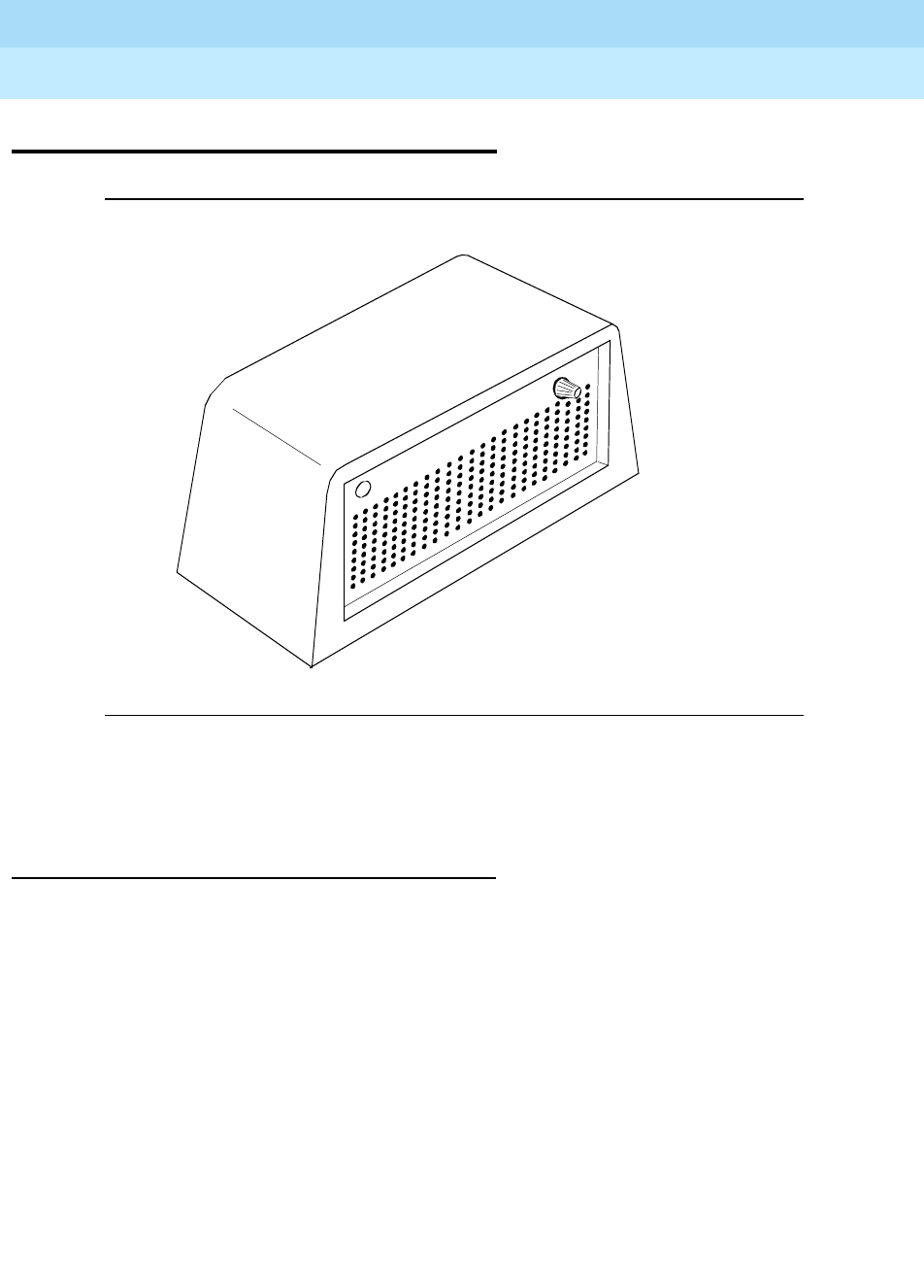
DEFINITYEnterpriseCommunicationsServerandSystem75andSystem85
Terminals and Adjuncts Reference
555-015-201 Issue 11
December 1999
Adjuncts
20-41The 107-Type Loudspeaker
20
The 107-Type Loudspeaker
Figure 20-15. The 107-Type Loudspeaker
The 107-Type Loudspeaker amplifies the received voice signal. This allows the
user to hear better in an noisy environment.
Applications
The loudspeaker can be used with the DEFINITY Communications System
Generic 1, Generic 2, and Generic 3, the DEFINITY ECS, System 75, and
System 85. It is used only with 2500-type voice terminals on “in place” basis. It is
particularly useful in a conference room or noisy room.

DEFINITYEnterpriseCommunicationsServerandSystem75andSystem85
Terminals and Adjuncts Reference
555-015-201 Issue 11
December 1999
Adjuncts
20-42The 107-Type Loudspeaker
20
Physical Description
Dimensions
NOTE:
The following dimensions are approximate.
Width = 5-3/4 inches
Depth (front to back) = 3-3/4 inches
Height = 4 inches
Features
Volume control
The loudspeaker is equipped with a rotary volume control.
ON/OFF switch
The ON/OFF switch turns the loudspeaker on and off when placed in the
appropriate setting.
Power
The 107-Type Loudspeaker requires an external AC or DC power source. This
power may be provided by an 2012D Transformer, 18-volt AC terminals of an
available power plant, or a 24-volt DC key system battery.
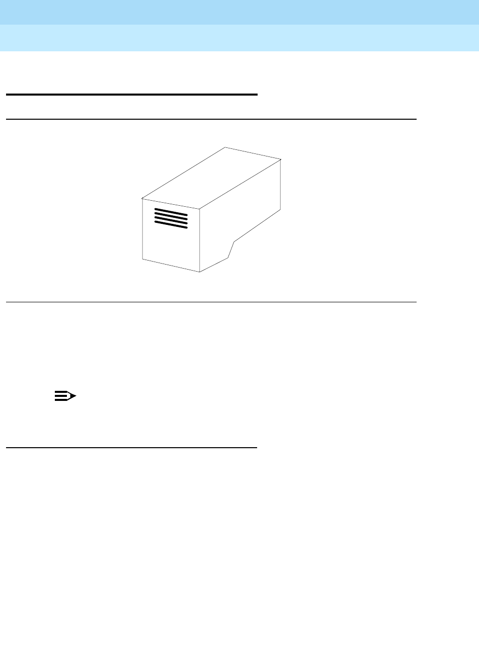
DEFINITYEnterpriseCommunicationsServerandSystem75andSystem85
Terminals and Adjuncts Reference
555-015-201 Issue 11
December 1999
Adjuncts
20-43The 7404D (Voice Terminal) Messaging Cartridge
20
The 7404D (Voice Terminal) Messaging
Cartridge
Figure 20-16. The Messaging Cartridge
This Messaging Cartridge adjunct can be added to a 7404D Voice Terminal to
provide displays on an associated data terminal. The messaging cartridge plugs
into the bottom of the 7404D Voice Terminal. The basic messaging cartridge
generates displays of call-related and personal-service information only.
NOTE:
The 7404D Messaging Cartridge was discontinued in July 2090.
Applications
The messaging cartridge is used with a 7404D voice terminal that is equipped
with a data terminal. The 7404D and messaging combination can be used with a
DEFINITY Communications System Generic 1, Generic 2, and Generic 3, the
DEFINITY ECS, System 75, or System 85.

DEFINITYEnterpriseCommunicationsServerandSystem75andSystem85
Terminals and Adjuncts Reference
555-015-201 Issue 11
December 1999
Adjuncts
20-44The 7404D (Voice Terminal) Messaging Cartridge
20
Considerations
A selection of the following display functions must be assigned to letter keys on
the keyboard of the associated data terminal:
■Normal Mode
■Inspect
■Message Retrieval
■Next
■Make Call
■Delete Message
■Date/Time
Messaging Cartridge PECs
The messaging cartridge attached to the 7404D voice terminal was ordered using
the following PEC:
■Messaging Feature Cartridge — PEC: 31810
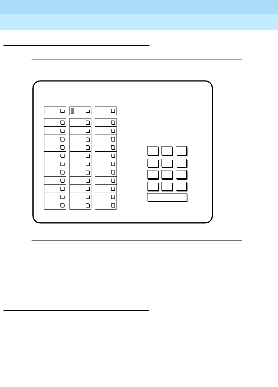
DEFINITYEnterpriseCommunicationsServerandSystem75andSystem85
Terminals and Adjuncts Reference
555-015-201 Issue 11
December 1999
Adjuncts
20-45The 2870A1 Automatic Dialer
20
The 2870A1 Automatic Dialer
Figure 20-17. The 2870A1 Automatic Dialer
The 2870A1 Automatic Dialer is an optional add-on adjunct for a MET set that is
provided on an “in place” basis only. The dialer provides the capability to record
and automatically dial 31 numbers of up to 15 digits each. It also provides last
number dialed (manually) memory and the capability to pause for subsequent dial
tones during automatic dialing (WAIT input).
Applications
The automatic dialer can be used with the DEFINITY Communications System
Generic 1, Generic 2, and Generic 3, the DEFINITY ECS, System 75, and
System 85. It is particularly useful for applications where several numbers must
be repeatedly dialed.
123
456
789
ABC DEF
MNOJKLGHI
PRS TUV WXY
*
O#
Oper
123
456
789
ABC DEF
MNOJKLGHI
PRS TUV WXY
*
O#
Oper
RECORD OFF RECORD WAIT
LAST NUMBER
DIALED

DEFINITYEnterpriseCommunicationsServerandSystem75andSystem85
Terminals and Adjuncts Reference
555-015-201 Issue 11
December 1999
Adjuncts
20-46The 2870A1 Automatic Dialer
20
Physical Description
Features
Programmable buttons
The automatic dialer has 31 buttons on which telephone numbers of up to
15 digits can be stored for one button dialing.
Four Fixed function buttons
■Record Off
■Record (Equipped with an Indicator)
■Wait
■Last Number Dialed
Other Physical Features
Dial pad
The automatic dialer is equipped with a 12-button touch-tone dial pad.
Power
The 2870A1 Automatic Dialer requires auxiliary power from an external source.
Refer to the Adjunct Power section earlier in this manual for the recommended
power supply.
Automatic Dialer PECs
The 2870A1 Automatic Dialer can be ordered using the following PECs:
■2870A1 Automatic dialer
(Silver)— PEC: 3113-030FPC01
(Teak)— PEC: 3113-030FPC02
(Walnut)—PEC: 3113-030FPC03

Data Modules
21-1
21
DEFINITYEnterpriseCommunicationsServerandSystem75andSystem85
Terminals and Adjuncts Reference
555-015-201 Issue 11
December 1999
21
Data Modules
This section describes the devices that provide a data communications interface.
Information on the data modules and other related data equipment used with the
DEFINITY Communications System Generic 1, Generic 2, and Generic 3, the
DEFINITY ECS, System 75, and System 85 is provided here. The following
devices described in this section provide data interface functions such as
modems, protocol converters, and data units.
■7400A Data Module
■7400B and 7400B Plus Data Module
■7400D Low-Speed Asynchronous Data Module
■8400B Plus Data Module
■7500B Data Module
■ISDN Asynchronous Data Module (ADM)
■Digital Terminal Data Module (DTDM)
■Z702AL1 Data Service Unit (DSU)
■703A Data Service Unit (DSU)
■DEFINITY High Speed Link (HSL)
■Processor Data Module (PDM)
■Trunk Data Module (TDM)

DEFINITYEnterpriseCommunicationsServerandSystem75andSystem85
Terminals and Adjuncts Reference
555-015-201 Issue 11
December 1999
Data Modules
21-2
21
■Modular Processor Data Module (MPDM)
■Modular Trunk Data Module (MTDM)
■3270 Data Module
■Asynchronous Data Unit (ADU)
■Multiple Asynchronous Data Unit (MADU)
■DCIU Interface Units
■2500-Series Data Service Unit (DSU)
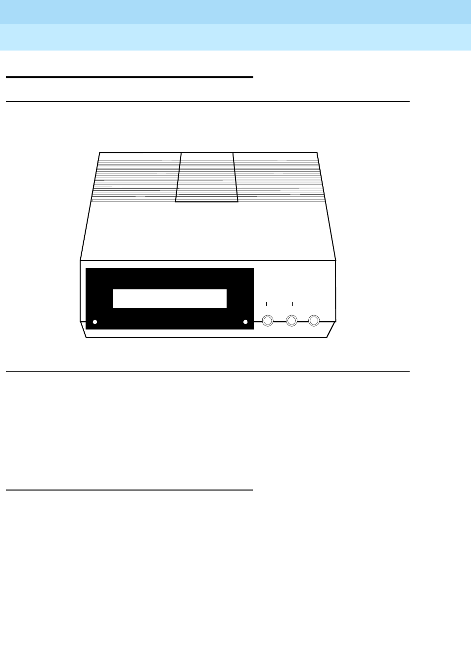
DEFINITYEnterpriseCommunicationsServerandSystem75andSystem85
Terminals and Adjuncts Reference
555-015-201 Issue 11
December 1999
Data Modules
21-3The 7400A Data Module
21
The 7400A Data Module
Figure 21-1. The 7400A Data Module
The 7400A Data Module is a full duplex asynchronous data module designed to
replace both the TDM (MTDM) and PDM (MPDM) for asynchronous applications.
The 7400A provides a DCP interface to the PBX and an RS-232-D (formerly
RS-232-C) interface to a DTE such as host computers, personal computers, and
terminals or DCE modems in external modem pool installation.
Applications
The 7400A data module can be used with the DEFINITY Communications System
Generic 1, Generic 2, and Generic 3, the DEFINITY ECS, System 75, and
System 85. It can be used in the modem pooling feature or for host access.
POWER/ DATA
7400A Data Module
DTR
RI
DCD
DTR
RTS
CTS
TD
RD
DSR
ENTER / YESBACKNEXT / NO
HOME
TEST

DEFINITYEnterpriseCommunicationsServerandSystem75andSystem85
Terminals and Adjuncts Reference
555-015-201 Issue 11
December 1999
Data Modules
21-4The 7400A Data Module
21
Physical Description
Dimensions
NOTE:
The following dimensions are approximate.
Width = 7 inches
Depth (front and rear) = 8-3/4 inches
Height = 1-3/4 inches
Features
Lights
■POWER/TEST light — This red light goes on when the 7400A data module
is on and flashes during all tests.
■DATA light — This green light goes on during a data call and flashes when
receiving an incoming call.
Display
The 16-character LCD display shows the status, option information, test
information, and also information about the RS-232-D interface of the data
module.
NEXT/NO, BACK, and ENTER/YES buttons
These buttons are used to view and set data communication options and
functions, adjust the contrast of the display, and to conduct tests.
Other Physical Features
Jacks
The 7400A data module is equipped with the following jacks.
■PORT 1 (EIA RS-232-C or -D)
■PHONE (not used)
■LINE (to switch) (RJ-45)
■POWER

DEFINITYEnterpriseCommunicationsServerandSystem75andSystem85
Terminals and Adjuncts Reference
555-015-201 Issue 11
December 1999
Data Modules
21-5The 7400A Data Module
21
Mounting Options
The 7400A data module can be configured as a stand-alone unit or in a
multiple-mount housing. (The multiple-mount housing
must be used
if D-lead
modems are used in the modem pool. The multiple-mount can also be used to
support Hayes-compatible modems.)
Color Options
The 7400A Data Module is available in misty cream only.
Tests
The 7400A data module supports the following test and maintenance features:
■Self-test
■Local loopback and remote loopback
■Local Loop self test and remote loop self test
■DCP looparound
■Maintenance activate
■Make busy
■Manual on-hook/off-hook
Capabilities
The basic features and capabilities of the 7400A data module are:
■DCP mode 2 operation only
■Full-duplex, 10-bit start/stop, asynchronous operation
■Asynchronous data rates of 0.3, 1.2, 2.4, 4.8, 9.6, and 19.2 kbps
■Even, odd mark, and space parity options
■Automatic answer option
■Signal loss disconnect option
■Autobaud
■Autoparity
■Long-break and triple-break disconnect options
Data features for modem pooling applications include:
■EIA RS-232-D DTE interface, enhanced with CI2 and CH2 leads
■Interface for D-lead control modems
■Interface for Hayes-compatible modems

DEFINITYEnterpriseCommunicationsServerandSystem75andSystem85
Terminals and Adjuncts Reference
555-015-201 Issue 11
December 1999
Data Modules
21-6The 7400A Data Module
21
Data features for host or terminal applications include:
■EIA RS-232-D DCE interface
■Keyboard dialing and Hayes user interface emulation option
■Answer only
■Cyclic Ring-indicator option
■Ignore DTR input option
Power
The stand-alone 7400A data module operates with power from a WP90110 L7 AC
power converter. This is a modular AC to DC adapter that is normally plugged into
a wall outlet. The Z77A Data Mounting has a built-in power supply for powering
data modules in the multiple-mount arrangement.
Considerations
The 7400A data module will NOT support the following:
■Linked operation with associated DCP telephone
■Synchronous Data transmission
■Asynchronous User Interface (AUI)
■DCP Mode 0, 1, 3, and Mode 2/3 adaptive
FCC Registration
No digital phones or data modules are FCC registered. The 7400A data module
meets Part 15 Class A requirements and is labeled as such.
7400A Data Module PECs
The 7400A data module can be ordered using the following PECs:
■7400A Data Module — 2171-ADM
■Stand-alone Power Supply — 21625
■7400A Multiple Mounting — 21626

DEFINITYEnterpriseCommunicationsServerandSystem75andSystem85
Terminals and Adjuncts Reference
555-015-201 Issue 11
December 1999
Data Modules
21-7The 7400A Data Module
21
Additional Documents
The following documents contain additional information relating to the 7400A data
module:
■
7400A Data Module User’s Manual
, 555-020-706
■
7400A Data Module Installation Guide
, 555-020-708
■
System 85 Application Notes for External Modem Pooling
, 555-109-005
■
System 85 Application Notes for Host Access Operation
, 555-109-004
■
System 75 Application Notes for External Modem Pooling
, 555-209-016
■
System 75 Application Notes for Host Access Operation
, 555-209-015
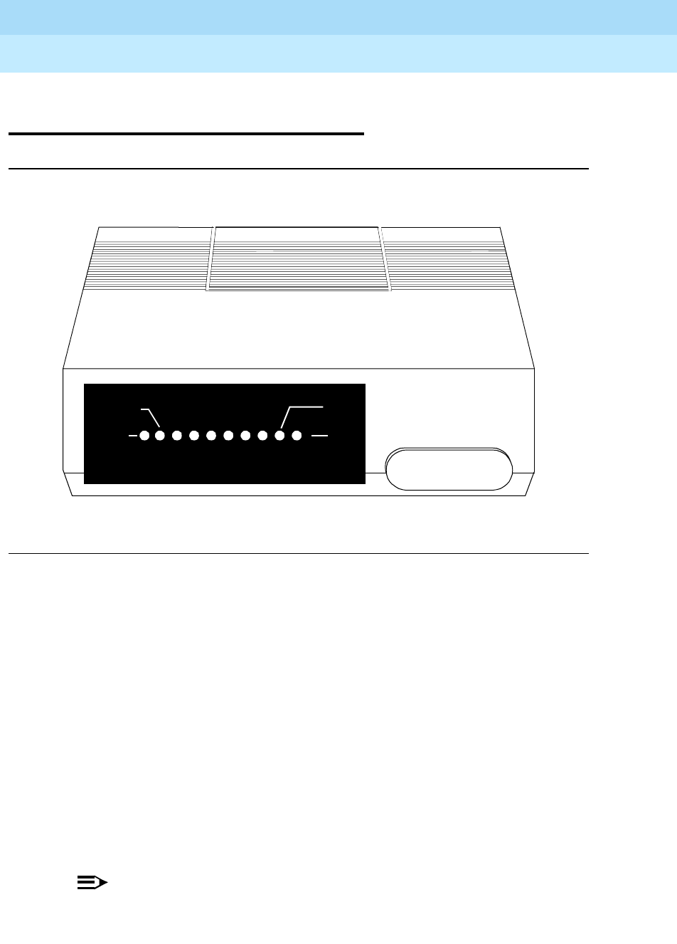
DEFINITYEnterpriseCommunicationsServerandSystem75andSystem85
Terminals and Adjuncts Reference
555-015-201 Issue 11
December 1999
Data Modules
21-8The 7400B and 7400B Plus Data Module
21
The 7400B and 7400B Plus Data
Module
Figure 21-2. The 7400B Plus Data Module
The 7400B and 7400B Plus Data Modules are full-duplex asynchronous,
Hayes-compatible data modules that provide for simultaneous voice-data
communications at the desk top over standard twisted pair wiring. The 7400B data
module has been discontinued; however, the 7400B Plus data module has all of
the basic characteristics of the 7400B, with the following added benefits:
■Supports the semicolon dial modifier, which enables an automatic return to
the command mode after dialing a data call
■Offers a storable S7 register, which supports increased call set-up time
■Offers the voice dial capability, which provides the ability to dial a voice call
from the PC package in the attached PC
Both of these data modules replace the existing PDM (MPDM) for asynchronous
communication, DTDM, and data stands for 7406D and 7407D voice terminals
(703A DSU and 702AL1) and the 7404D integrated voice/data phone.
NOTE:
If you have a 7400B data module and want to have the voice dial feature,
you can upgrade your current 7400B with a D-kit (Comcode: 106414543)
orderable through the National Parts Sales Center at 1 800 222-PART.
DATA
METERING
POWER
TEST
AA CD RD SD TR OH
DATA
CHECK
SPEED
7400B Data Module
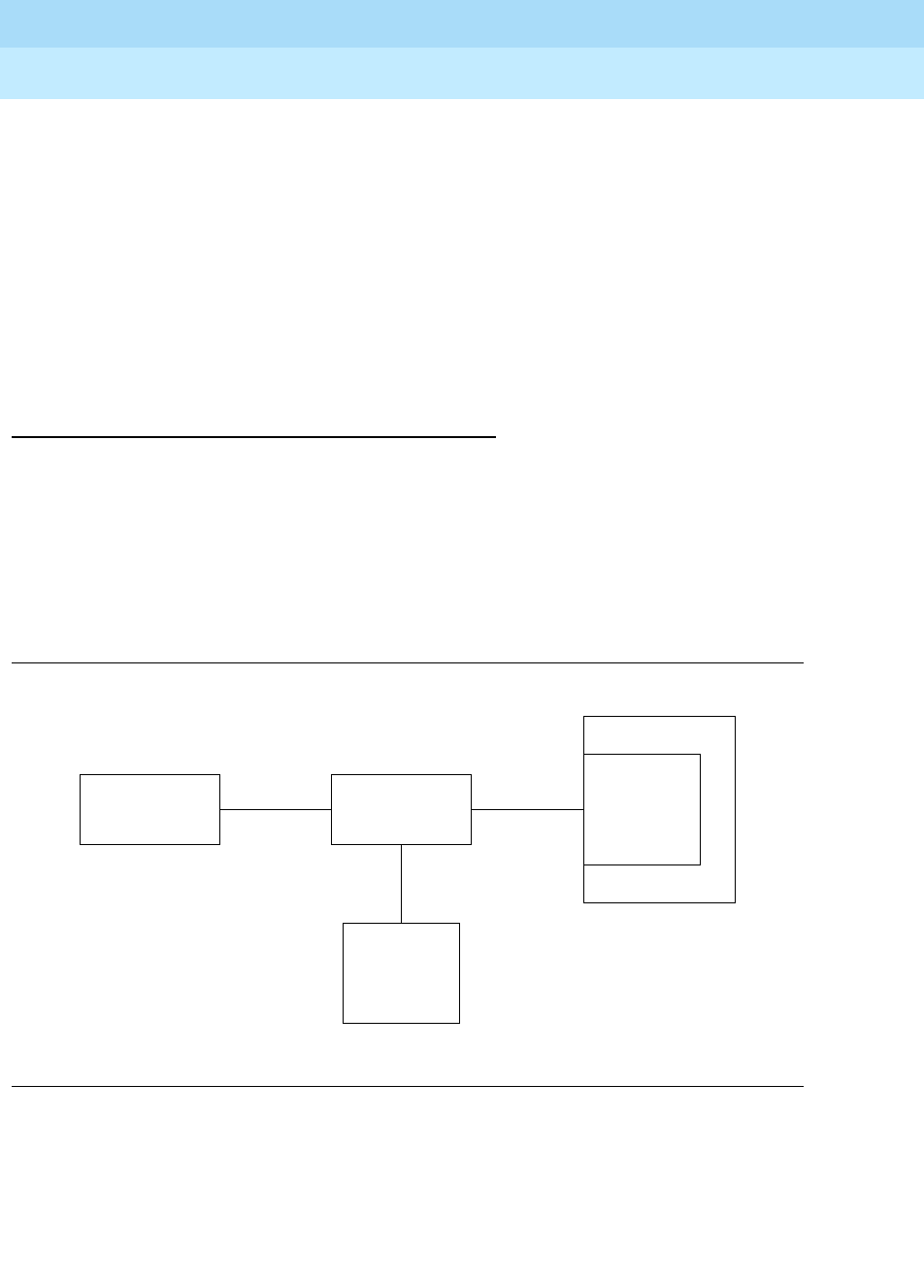
DEFINITYEnterpriseCommunicationsServerandSystem75andSystem85
Terminals and Adjuncts Reference
555-015-201 Issue 11
December 1999
Data Modules
21-9The 7400B and 7400B Plus Data Module
21
In the linked mode, the 7400B and 7400B Plus data modules provide for
simultaneous voice data communications over standard twisted pair wiring. In this
mode, the 7400B and 7400B Plus data modules can be used with all DCP voice
terminals to provide data service. The 7400B Plus provides the voice dial feature
for all DCP voice terminals
except
the following:
■7403D voice terminal (all models)
■7404D voice terminal (all models)
■7405D voice terminal (all models)
■7407D01A voice terminal
Applications
The 7400B and 7400B Plus data modules can be used with the DEFINITY
Communications System Generic 1, Generic 2, and Generic 3, the DEFINITY
ECS, System 75, and System 85. The data modules are used as a DCE for host
access services, PC, or terminal (DTE) connectivity (see Figure 21-3).
Figure 21-3 shows a diagram of the connections between the 7400B or 7400B
Plus and the data terminal, the digital voice terminal, and the switch.
Figure 21-3. A Block Diagram of the 7400B Interface
Data
Terminal
Data
Service
Digital Switch
RS-232C
Unit
DCP Digital
Line
Port
7400B or
7400B Plus
Digital
Voice
Terminal

DEFINITYEnterpriseCommunicationsServerandSystem75andSystem85
Terminals and Adjuncts Reference
555-015-201 Issue 11
December 1999
Data Modules
21-10The 7400B and 7400B Plus Data Module
21
Physical Description
Dimensions
NOTE:
The following measurements for the 7400B and 7400B Plus data module
are approximate.
Width = 7 inches
Depth (front and rear) = 8-3/4 inches
Height = 1-3/4 inches
Features
Lights
■POWER/TEST light — The red POWER/TEST light goes on when AC
power is supplied to the 7400B or 7400B Plus data module and flashes
during all tests. This light, together with the DATA light, also flashes if there
is a DCP line problem.
■DATA light — The green DATA light goes on during a data call. This light,
together with the POWER/TEST light, flashes if there is a DCP line
problem.
■Other lights — The eight other lights show the RS-232 status information,
the status of two options, and call status information. These lights are red.
Other Physical Features
Jacks
The 7400B and 7400B Plus data modules are equipped with the following jacks:
■Port 1 (RS-232-C or -D)
■PHONE (to voice terminal) (RJ-45)
■LINE (to switch) (RJ-45)
■POWER
Mounting Options
The 7400B and 7400B Plus data modules can be desk-mounted as a stand-alone
unit.
Color Options
The 7400B and 7400B Plus data modules are available only in misty cream.

DEFINITYEnterpriseCommunicationsServerandSystem75andSystem85
Terminals and Adjuncts Reference
555-015-201 Issue 11
December 1999
Data Modules
21-11The 7400B and 7400B Plus Data Module
21
Tests
The 7400B and 7400B Plus data modules support the following test and
maintenance features:
■Local Loopback and Remote Loopback
■Local Loopback Self Test and Remote Loop Self Test
■DCP Looparound
■Self-Test
■Make Busy on Local Loop
Capabilities
The 7400B and 7400B Plus data modules have the following basic features and
capabilities:
■DCP mode 2 operation only
■Full-duplex, 10-bit start/stop, asynchronous operation
■Asynchronous data rates of 0.3, 1.2, 2.4, 4.8, 9.6, and 19.2 kbps
■Even, odd, mark, and space parity options
■Autobaud and autoparity
■Linked operation with the associated DCP voice terminal
■Data metering — Data metering allows the data module and associated
terminal to operate at higher speeds than the far-end data point.
■Supports the semicolon modifier which enables an automatic return to the
command mode after dialing a data call (for 7400B Plus).
■Voice Dial (for 7400B Plus) — This feature allows you to initiate voice calls
from your PC using the dial command “atdp number.” These calls must be
terminated manually, however.
■Speakerphone Activation before Dialing (for 7400B Plus) — For terminal
dialed voice calls, you can delay speakerphone activation until after a call is
dialed. You would not hear touch tones or dial tone in this case.
■Wait Time for Carrier (for 7400B Plus) — The number stored in the
S7 register establishes the time the 7400B Plus data module will wait for
call set up to be completed. This number can be set for any value up to a
maximum of 255 seconds (with a default to 60 seconds).
Data features for host or terminal applications include:
■EIA RS-232-D DCE interface
■Hayes SMARTMODEM 2400™user interface emulation

DEFINITYEnterpriseCommunicationsServerandSystem75andSystem85
Terminals and Adjuncts Reference
555-015-201 Issue 11
December 1999
Data Modules
21-12The 7400B and 7400B Plus Data Module
21
Power
The stand-alone 7400B and 7400B Plus data modules operate with power from a
WP91508L5 AC power converter. This is a modular AC to DC adapter that is
normally plugged into a wall outlet. The data module allows phantom power to be
transmitted to the attached DCP voice terminal even if AC power to the data
module is interrupted.
Setting Options
After removal of the top access panel of the data module during installation, it is
important to verify that the eight option switches are set to provide the desired
features.
■SW1-1—With/Without Telephone Option
This switch must be set to ON for operation
without
an associated
telephone. This switch must be set to OFF for operation
with
an associated
telephone.
■SW1-2 (Not used)
■SW1-3 (Not used)
■SW1-4 (Not used)
■SW1-5—Data Metering Option
When this switch is set to ON, the data module and associated terminal
can operate at higher speeds than the far-end data point. This switch is
usually set to OFF.
■SW1-6—Suppress Touch-Tone/Dial Tone (for 7400B Plus)
Leave this switch set to OFF if the user prefers listening to Touch-Tones as
voice calls are being dialed. Set the switch to ON if the user wants to
suppress Touch-Tones. If the user is using a speakerphone, ringing will be
heard after the call has been made.
■SW1-7—Speakerphone Enable/Disable Option (for 7400B Plus)
Leave this switch set to OFF if the user wants the speakerphone to turn on
automatically when the terminal is used to make a voice call. Set the switch
to ON if there is no speakerphone or if the user wants to disable the
speakerphone automatic activation feature.
■SW1-8—Make Busy on Local Loop Option
This switch should be set to ON if the user wants the telephone line to
appear busy when the local loopback test feature is used to check the
interface between the data module and the terminal.

DEFINITYEnterpriseCommunicationsServerandSystem75andSystem85
Terminals and Adjuncts Reference
555-015-201 Issue 11
December 1999
Data Modules
21-13The 7400B and 7400B Plus Data Module
21
Notes for Use with PC Packages
The 7400B Plus voice and data feature has been tested with the following PC
communication packages:
■CARBON COPY Plus™ V5.1
■Crosstalk®- XVI V3.71
■Crosstalk Mk.4 V1.1
■Hot Line V2.2 (voice dialing packages)
■HyperACCESS®V3.32
■MicroPhone V1.5 (MacIntosh package)
■PC TOOLS Deluxe V6 (voice dialing packages)
■Procomm Plus®V1.1B
■Relay Gold®V3.0
■SideKick®V1.5 and SideKick Plus (voice dialing packages)
■Smartcom™II V2.2
■Smartcom II V3.1
■Smartcom III V1.1
■Smarterm 240 V3.0a
■Terra Nova®V1.1.1
■White Knight V11 (MacIntosh package)
For those PC packages used to dial voice calls, the modem configuration must be
set to PULSE (P) (even though the 7400B Plus will use Touch-Tone for voice
calls). If given a choice, set modem type to HAYES.
NOTE:
While the 7400B Plus supports simultaneous voice and data, the packages
listed here support
alternate voice/data dialing only
. Voice dialing packages
interfere with data operation by remapping the COM port or by hanging up
the data call.
You
can
dial a data call while on a voice call. In all cases, the linked telephone will
work.
FCC Registration
These data modules are not FCC registered. The 7400B and 7400B Plus data
modules meet Part 15 Class A requirements and are labeled as such.

DEFINITYEnterpriseCommunicationsServerandSystem75andSystem85
Terminals and Adjuncts Reference
555-015-201 Issue 11
December 1999
Data Modules
21-14The 7400B and 7400B Plus Data Module
21
7400B Data Module PECs
The 7400B and 7400B Plus data modules can be ordered using the following
PECs:
■7400B Plus Data Module
PEC: 2172-101
Comcode: 106545841
NOTE:
The 7400B Plus data module comes with a stand-alone power
supply.
Additional Documents
The following documents contain additional information relating to the 7400B and
7400B Plus data modules:
■
7400B Data Module User’s Guide
, 555-020-707
■
7400B Plus Data Module User’s Guide
, 555-020-710
■
DEFINITY Communications System Generic 1 and System 75 R1V2
Through R1V3 7400B Data Module Application Notes
, 555-209-017
■
7400B Data Module PC Applications Guide
, 555-035-203
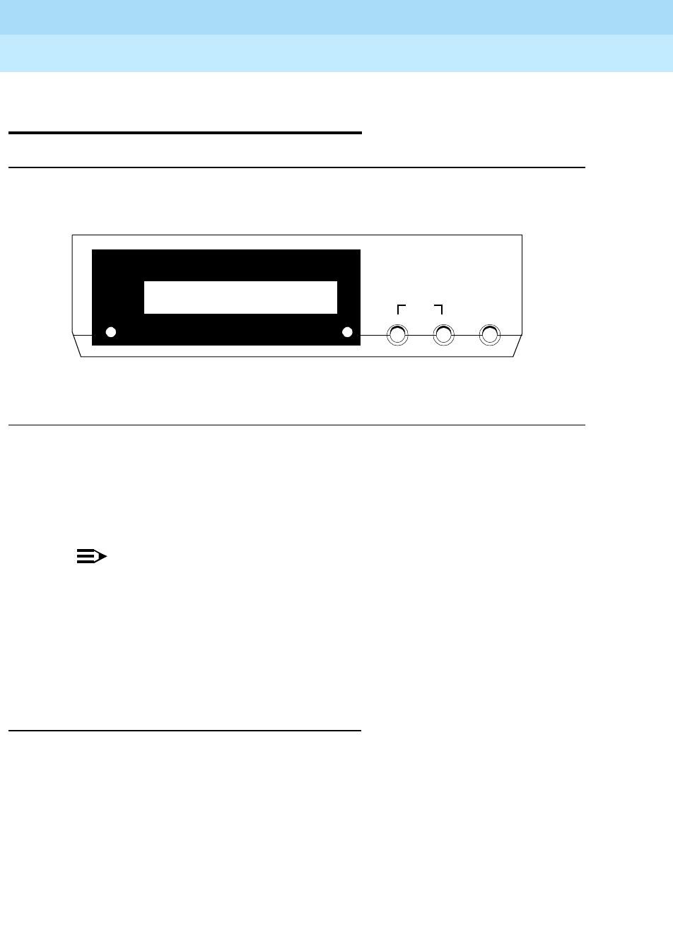
DEFINITYEnterpriseCommunicationsServerandSystem75andSystem85
Terminals and Adjuncts Reference
555-015-201 Issue 11
December 1999
Data Modules
21-15The 7400D Low-Speed Asynchronous Data Module
21
The 7400D Low-Speed Asynchronous
Data Module
Figure 21-4. The 7400D Data Module
The 7400D Data Module is a full-duplex, 4-wire synchronous data module for the
DCP environment and is designed to work where the integration of voice and data
is not required. The 7400D supports synchronous connections at speeds up to
19.2 Kbps via an EIA-232-D interface.
NOTE:
This data module is configured for an Answer-Only-type interface.
You CANNOT originate calls with this data module.
The 7400D data module is intended for use in a switch room to support the AUDIX
systems, the Call Management System (CMS), and the Distributed
Communications System (DCS) low speed synchronous data applications,
connections in which the MPDM was formerly used.
Applications
The 7400A Data Module can be used with the DEFINITY Communications
System Generic 1, Generic 2, and Generic 3, the DEFINITY ECS, System 75, and
System 85.
POWER
TEST DATA
7400D Data Module
ENTER/YESBACKNEXT/NO
HOME
DTR
RI
DCD
DTR
RTS
CTS
TD
RD
DSR

DEFINITYEnterpriseCommunicationsServerandSystem75andSystem85
Terminals and Adjuncts Reference
555-015-201 Issue 11
December 1999
Data Modules
21-16The 7400D Low-Speed Asynchronous Data Module
21
Physical Description
Dimensions
The following dimensions are approximate.
Width = 7 inches
Depth (front and rear) = 8-3/4 inches
Height = 1-3/4 inches
Features
Front Panel
The front panel is comprised of:
Two LEDs, one red and one green
— POWER/TEST light — This red light goes on when the 7400D data
module is on, and it flashes during all tests
— DATA light — This green light goes on when a data call is in
progress, and it flashes when receiving an incoming call. This light
also flashes synchronously with the red light indicating that the
connection to the PBX is lost.
■A single line, 16-character LCD display — The 16-character LCD display
first shows a start-up sequence consisting of self-test results, hardware
configuration, software release and version, and copyright information.
Following start-up, the Home screen is displayed.
■Three non-locking push-buttons
— NEXT/NO button — This button is used to scroll forward through the
menu and/or reject the function displayed. By keeping this button
depressed, you are able to quickly scroll through menu items.
NOTE:
When you press NEXT/NO and BACK simultaneously, you are
automatically returned to the Home screen from many menus.
However, do not press these two keys simultaneously while changing
option values. If this is done, rather than returning you to the Home
screen, the system queries if you want to save the changes you have
made.

DEFINITYEnterpriseCommunicationsServerandSystem75andSystem85
Terminals and Adjuncts Reference
555-015-201 Issue 11
December 1999
Data Modules
21-17The 7400D Low-Speed Asynchronous Data Module
21
— BACK button — This button is used to scroll backward through the
menu. By keeping this button depressed, you are able to quickly
scroll back through menu items.
— ENTER/YES button — This button is used to set an option or
execute the function displayed.
The Main Menu
The Main Menu has several levels of options and suboptions. By pressing
NEXT/NO, you are able to scroll through the entire first level to view each option
shown in the flowchart below.
After scrolling to the desired Main Menu option and selecting it by pressing
ENTER/YES, you are now one level deeper within the options, and a suboptions
choice is presented to you.
Other Physical Features
Jacks
The 7400D data module is equipped with the following jacks:
■PHONE — not used by the 7400D
■LINE — accepts one end of the D8W telephone cord that connects the
data module and the PBX wall jack
■POWER — accepts the output cable of the separate power supply unit
used with the 7400D
■PORT 1 — accepts a male plug from the EIA-232-D cable that connects
between the data module and associated equipment
■PORT 2 — not used by the 7400D
Mounting Options
The 7400A data module can be configured as a stand-alone unit or in a
multiple-mount housing.
The parts required for installing a single 7400D are:
■The 7400D data module
■An AC power converter
■A D8W telephone line cord
■An EIA RS-232-D cable
The 7400D data module can also be mounted in a new or existing 77A Data
Mounting for multiple data module applications. The data mounting rack is
provided with a built-in power supply and cables for distributing power for up to
eight data modules.

DEFINITYEnterpriseCommunicationsServerandSystem75andSystem85
Terminals and Adjuncts Reference
555-015-201 Issue 11
December 1999
Data Modules
21-18The 7400D Low-Speed Asynchronous Data Module
21
Power Supply Unit
An individual power supply unit is required with the 7400D data module
only when
it is used as a stand-alone module
. When the 7400D is rack-mounted in a 77A
rack-mount, the rack-mount provides powering capabilities for up to eight units.
The power supply unit connects a grounded AC outlet and the “POWER”
connector at the rear of the data module. This power supply unit provides the
necessary operating voltages for the data module.
Tests
The 7400D data module supports only the Self- test.
Data Module Features
You can control the following operations via the 7400D’s front panel:
■Option settings
■Self-Test and Reset Options features
■Adjustment of the contrast on the display
■Answer/disconnect and busyout
The following features are also available:
■Automatic or manual answering of incoming data calls
■Synchronous full-duplex operation
■Data rates of 300, 1200, 2400, 4800, 9600, and 19,200 bits per second
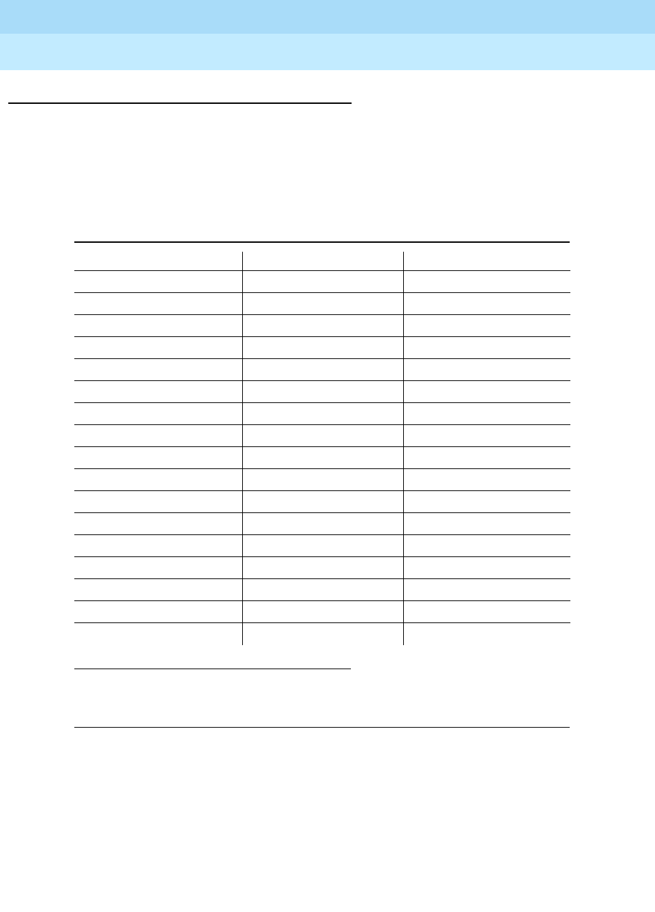
DEFINITYEnterpriseCommunicationsServerandSystem75andSystem85
Terminals and Adjuncts Reference
555-015-201 Issue 11
December 1999
Data Modules
21-19The 7400D Low-Speed Asynchronous Data Module
21
Setting Options
The following table presents the choices for each option of the Answer Only user
interface and the order in which the are presented in the menu. All options must
be set from the front panel. This table also shows the factory default for each
option. (The FACTORY DEFAULT values are typed in larger type and in bold.)
Table 21-1. Options Available to the Answer Only Interface and
Their Default Settings
Set Option Displays Option Abbreviations Possible Values
SET 300 SPEED? 300 ON,OFF
SET 1200 SPEED? 1200 ON,OFF
SET 2400 SPEED? 2400 ON,OFF
SET 4800 SPEED? 4800 ON,OFF
SET 9600 SPEED? 9600 ON,OFF
SET 19200 SPEED? 19200 ON,OFF
SET ANSWER?*
* On the MPDM, the SET ANSWER option is labeled AANS/OFF.
the SET SIGLS DISC option on the MPDM is labeled SIGLS/OFF.
ANS AUTO,MANUAL
SET CI LEAD? CI ON, OFF
SET CH LEAD? CH ON, OFF
SET CTS LEAD? CTS NORMAL,ON
SET DCD LEAD? DCD NORMAL,ON
SET DSR LEAD? DSR NORMAL,ON
SET DTR DETECT? DTR 0,10,20,30,50,100 MSEC
SET DTR LEAD? DTR EIA STANDARD,IGNORE
SET RI LEAD? RI CYCLE, ON
SET SIGLS DISC?*SIGLS DISC ON,OFF
SET TM LEAD? TM ON, OFF

DEFINITYEnterpriseCommunicationsServerandSystem75andSystem85
Terminals and Adjuncts Reference
555-015-201 Issue 11
December 1999
Data Modules
21-20The 7400D Low-Speed Asynchronous Data Module
21
FCC Registration
No digital phones or data modules are FCC registered. The 7400D data module
meets Part 15 Class A requirements and is labeled as such.
7400D Data Module PECs
The 7400D Data Module can be ordered using the following PECs:
■7400D Data Module
PEC: 2161-LSS
Comcode: 107669954
■Domestic Stand-alone Power Supply
PEC: 21625
Comcode: 405509852
■Power Supply for Western Europe
PEC: 2161-CEP
Comcode: 407573559
Additional Documents
The following document contains additional information relating to the 7400D
Data Module:
■
7400D Data Module User’s Guide
, 555-020-712
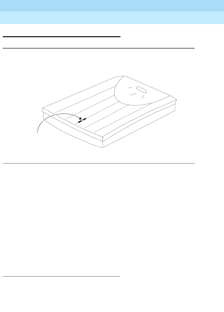
DEFINITYEnterpriseCommunicationsServerandSystem75andSystem85
Terminals and Adjuncts Reference
555-015-201 Issue 11
December 1999
Data Modules
21-21The 8400B Plus Data Module
21
The 8400B Plus Data Module
Figure 21-5. The 8400B Plus Data Module
Like the 7400B Plus data module, the 8400B Plus Data Module is a full-duplex
asynchronous, data module that provides for simultaneous voice-data
communications at the desktop over standard twisted pair wiring. However, it has
been designed explicitly to work, in the linked mode, with 2-wire DEFINITY DCP
circuits. That is, this data module is a data service link between a DTE device, a
2-wire voice terminal such as the 8400-Series voice terminals, and a DEFINITY
G3V2 or later.
At the desk, the 8400B Plus data module provides asynchronous communication
speeds ranging from 0.3 to 19.2 kbps. The 8400B Plus data module’s ability to
emulate a Hayes compatible modem interface makes it compatible with many
standard PC communications packages that use Hayes Command sets. In
addition, the 8400B Plus data module provides a voice dial capability that allows
you to initiate voice calls from a PC using industry standard “auto-dialer” PC
communications packages.
Applications
The 8400B Plus data module can be used with the DEFINITY ECS G3V2 or later.
The data module is used as a DCE for host access services, PC, or terminal
(DTE) connectivity. The PC or other terminal device is connected to the 8400B
Plus data module using a standard EIA-232-D cable and, if needed, the supplied
The red and green
lights on front panel

DEFINITYEnterpriseCommunicationsServerandSystem75andSystem85
Terminals and Adjuncts Reference
555-015-201 Issue 11
December 1999
Data Modules
21-22The 8400B Plus Data Module
21
M9/F25 Adapter, an adapter which allows connection from a 9-pin jack to a 25-pin
jack. A DCP interface (using a D8W-type modular telephone cord) is used to
connect the 8400B Plus data module to the digital PBX.
The 8400B Plus data module may be optioned for use either with or without a
telephone. In the stand-alone case, the 8400B Plus data module supports data
service only. Otherwise, the 8400B Plus data module provides simultaneous data
and voice service. The 8400B Plus works with all DCP voice terminals that
support 2-wire operations (such as the 8400-Series voice terminals), to provide
simultaneous data and voice service.
The voice dial feature allows you to dial a voice call without touching the
telephone. Depending on your communications package, you may also store
telephone numbers on a PC and recall them for dialing, log phone calls for easy
billing, and take notes for later reference during a telephone conversation. In
addition, the 8400B Plus data module can be used to automatically turn on the
speakerphone of the voice terminal when a voice call is dialed from your terminal
device.
Figure 21-6 shows a standard configuration in the United States, using a
telephone and separate power supply. Figure 21-7 shows a standard international
configuration using a telephone and separate power supply. Both the US
configuration and the international configuration may be installed using a closet
power supply as shown in Figure 21-8. This last installation eliminates the need
for the separate power supply.
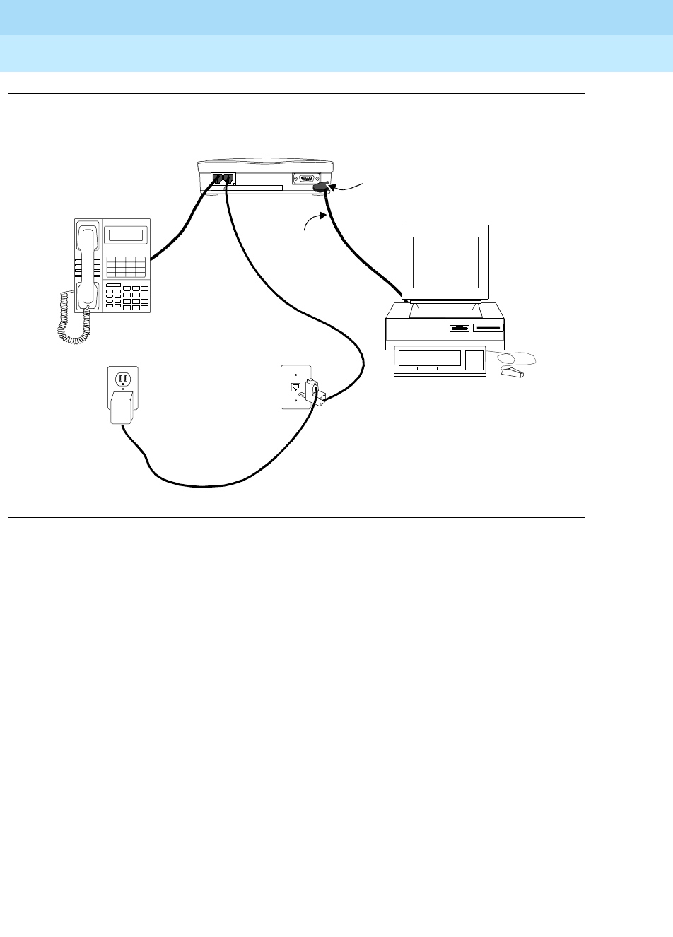
DEFINITYEnterpriseCommunicationsServerandSystem75andSystem85
Terminals and Adjuncts Reference
555-015-201 Issue 11
December 1999
Data Modules
21-23The 8400B Plus Data Module
21
Figure 21-6. Typical Installation of the US Configuration,
Including Telephone and Separate Power Supply
PHONE LINE/
POWER
!USE ONLY WITH COMMUNICATION
CIRCUIT POWER SOURCE (use only with 25-pin
(Rear Endplate)
EIA-232-D
D8W
M9/F25 Adapter
EIA-232-D Connector Cord)
(9-pin or 25-pin)
Connector Cord
Wall
D8W
D6AP
AC
Outlet
400B2
Adapter
KS-22911, L2 Jack
Power Supply
Telephone
(Optional)
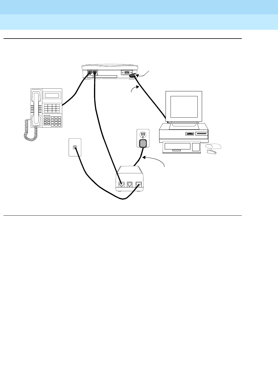
DEFINITYEnterpriseCommunicationsServerandSystem75andSystem85
Terminals and Adjuncts Reference
555-015-201 Issue 11
December 1999
Data Modules
21-24The 8400B Plus Data Module
21
Figure 21-7. Typical Installation of the International Configuration,
Including Telephone and Separate Power Supply
PHONE LINE/
POWER
!USE ONLY WITH COMMUNICATION
CIRCUIT PO WER S OURCE
(Rear Endplate)
MSP-1
Wall
D8W
D8W
Telephone
(Optional)
D8W
Jack
AC
LINEPHONE
-7 +8 OTHER
-2 +5
Outlet
M9/F25 Adapter
(use only with 25-pin
EIA-232-D Connector Cord)
Actual connection may vary
according to the configuration
of your local AC outlet
Power Supply
EIA-232-D
(9-pin or 25-pin)
Connector Cord
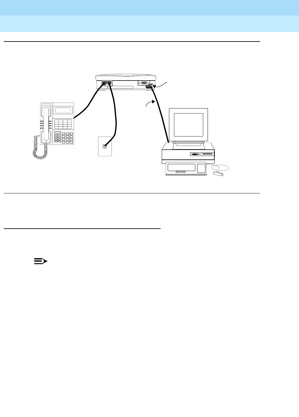
DEFINITYEnterpriseCommunicationsServerandSystem75andSystem85
Terminals and Adjuncts Reference
555-015-201 Issue 11
December 1999
Data Modules
21-25The 8400B Plus Data Module
21
Figure 21-8. Typical Installation of the US and International Configuration,
Including Telephone and Closet Power Supply
Physical Description
Dimensions
NOTE:
The following measurements for the 8400B Plus data module are
approximate.
Width = 5 inches
Depth (front and rear) = 7-3/4 inches
Height = 1-1/4 inches
Features
Lights
The front panel of the 8400B Plus has two lights, one red light and one green light.
These lights indicate the status of the set during normal operation and the result
of self-tests when initially powered.
PHONE LINE/
POWER
!USE ONLY WITH COMMUNICATION
CIRCUIT POWER SOURCE
(Rear Endplate)
Wall
D8W
EIA-232-D
D8W
M9/F25 Adapter
(use only with 25-pin
EIA-232-D Connector Cord)
(9-pin or
25-pin)
Connector
Cord
Jack
Telephone
(Optional)

DEFINITYEnterpriseCommunicationsServerandSystem75andSystem85
Terminals and Adjuncts Reference
555-015-201 Issue 11
December 1999
Data Modules
21-26The 8400B Plus Data Module
21
When power is first applied to the 8400B Plus data module, the unit performs a
self-test to verify that it is in working order. During the self-test, both lights will
remain ON. When the self-test is complete, the green light turns OFF
■If self-test passed, the red light will remain ON. This indicates that your
8400B Plus data module is installed and ready for data communications
operation.
■If self-test failed, the red light will FLASH (A Flash is a repeated pattern of
500 ms ON and 500 ms OFF.) three times, and then remain ON.
Other light indications are:
■Idle in Normal Mode — The green light is OFF; the red light is ON — This
is the unit’s normal mode if no active data call exists.
■Incoming Call — The green light FLASHES; the red light is ON — This
indicates an incoming call.
■Active Data Call — Both the green and red lights are ON — This indicates
an active data call.
■Test Modes (Other Than Self-Test) — Both green and red lights
FLASH — This indication shows that the data module is in test mode.
■Memory Error Mode — The green light is OFF; the red light FLASHES —
This indicates that the unit is defective. Call the Lucent Technologies
Technical Service Center at 1 800 242-2121.
■Switch Link Down — The green light WINKS (A Wink is a repeating
pattern of 750 ms ON and 250 ms OFF.); the red light emits an INVERTED
WINK (An Inverted Wink is a repeating pattern of 250 ms ON and 750 ms
OFF) — This indication shows that the unit is unable to communicate with
the PBX. Restore the connection between the 8400B Plus and the PBX
wall jack.
■Phone Link Down — The green light emits an INVERTED WINK; the red
light WINKS — This indicates that the unit is unable to communicate with
the telephone. Restore the connection between the 8400B Plus and the
telephone.
Other Physical Features
Jacks
The 8400B Plus data module is equipped with the following jacks:
■PHONE — This connector accepts one end of the D8W telephone line cord
used to connect a 2-wire voice terminal to the 8400B Plus data module.
■LINE/POWER — This connector accepts one end of the D8W telephone
cord that connects the 8400B Plus data module and either:
— a PBX wall jack already powered by a closet supply, or
— a power supply, which is connected to the PBX wall jack.

DEFINITYEnterpriseCommunicationsServerandSystem75andSystem85
Terminals and Adjuncts Reference
555-015-201 Issue 11
December 1999
Data Modules
21-27The 8400B Plus Data Module
21
■EIA CONNECTOR INTERFACE — This connector provides an interface
between the 8400B Plus data module and the terminal (DTE) device.
— If the communications port on the terminal device is a 9-pin
interface, use a cord with DB9 male connectors on each end to
connect the data module to the terminal device.
— If the communications port on the terminal device is a 25-pin
interface, use a 25-pin EIA-232-D cord, plus the supplied M9/F25
Adapter to connect the data module to the terminal device.
Mounting Options
The 8400B Plus data module can be desk-mounted.
Color Options
The 8400B Plus data module is available only in black.
Tests
The 8400B Plus data module supports the following test and maintenance
features:
■Local Loopback and Remote Loopback
■Local Loopback Self Test and Remote Loop Self Test
■DCP Looparound
■Self-Test
■Make Busy on Local Loop
Capabilities
The 8400B Plus data module has the following basic features and capabilities:
■Nonvolatile, read-write memory for storing installation options, two data
options profiles, and up to four telephone numbers
■Full-duplex, 10-bit start/stop, asynchronous operation
■Asynchronous data rates of 0.3, 1.2, 2.4, 4.8, 9.6, and 19.2 kbps
■Even, odd, mark, and space parity options
■Autobaud and autoparity
■Linked operation with the associated DCP voice terminal

DEFINITYEnterpriseCommunicationsServerandSystem75andSystem85
Terminals and Adjuncts Reference
555-015-201 Issue 11
December 1999
Data Modules
21-28The 8400B Plus Data Module
21
■An AT command interface that emulates a Hayes 2400 Smartmodem and
supports the following:
— storage of the wait time for carrier detect interval (S-register S7)
The number stored in the S7 register establishes the time the 8400B
Plus data module will wait for call set up to be completed. This
number can be set for any value up to a maximum of 255 seconds
(with a default to 60 seconds).
— voice call origination from your PC using the ATDP command
(however, these calls must be terminated manually)
■Data metering which allows the data module and associated terminal to
operate at higher speeds than the far-end data point
■Supports the semicolon modifier which enables an automatic return to the
command mode after dialing a data call
■Speakerphone Activation before Dialing
For terminal dialed voice calls, you can delay speakerphone activation until
after a call is dialed. You would not hear touch tones or dial tone in this
case.
■Power-up self-test
■Local and remote loopback tests with test duration timer
■Voice terminal powered by the PBX is not affected if AC power is removed
from the 8400B Plus data module
Data features for host or terminal applications include:
■EIA/RS-232-D DCE interface
■Hayes SMARTMODEM 2400 user interface emulation
Power
A Lucent Technologies power supply unit is shipped with each 8400B Plus data
module. This unit connects to a grounded AC outlet, and provides a connection
between the PBX wall jack and the 8400B Plus data module. The power supply
unit provides the necessary operating voltages for the 8400B Plus data module.
Setting Options
There are 28 S-registers in the 8400B Plus data module. Twenty-two S-registers
are used to store configuration parameters; one is used to store installation
options, and the remaining five are unused. Eleven registers can be stored in
nonvolatile memory, which will be restored when the unit is powered up. There are
two sets of stored registers, or profiles. When the 8400B Plus is first powered on,
the values that were last stored in the S-registers are the values in effect until AT
commands are issued to change them.

DEFINITYEnterpriseCommunicationsServerandSystem75andSystem85
Terminals and Adjuncts Reference
555-015-201 Issue 11
December 1999
Data Modules
21-29The 8400B Plus Data Module
21
You can check the current value stored in all S-registers with the
&V
command. To
look at the contents of just one register, use the command
Smm?
where “mm” is
the number of the S-register. The data module will return 3-digits, representing the
decimal value of the specified S-register.
To change the value in any one S-register directly, use the command
Smm=nnn
where “mm” is the number of the S-register and “nnn” is the number you wish to
place in the register.
For a full description of all 28 S-registers, see Appendix C in the
8400B Plus Data
Module User’s Guide
, 555-020-708.
Notes for Use with PC Packages
Like the 7400B Plus, the 8400B Plus is able to use the following PC
communication packages:
■CARBON COPY Plus V5.1
■Crosstalk XVI V3.71
■Crosstalk Mk.4 V1.1
■Hot Line V2.2 (voice dialing packages)
■HyperACCESS V3.32
■MicroPhone V1.5 (MacIntosh package)
■PC TOOLS Deluxe V6 (voice dialing packages)
■Procomm Plus V1.1B
■Relay Gold V3.0
■SideKick V1.5 and SideKick Plus (voice dialing packages)
■Smartcom II V2.2
■Smartcom II V3.1
■Smartcom III V1.1
■Smarterm 240 V3.0a
■Terra Nova V1.1.1
■White Knight V11 (MacIntosh package)

DEFINITYEnterpriseCommunicationsServerandSystem75andSystem85
Terminals and Adjuncts Reference
555-015-201 Issue 11
December 1999
Data Modules
21-30The 8400B Plus Data Module
21
For those PC packages used to dial voice calls, the modem configuration must be
set to PULSE (P) (even though the 8400B Plus will use Touch-Tone for voice
calls). If given a choice, set modem type to HAYES.
NOTE:
While the 8400B Plus supports simultaneous voice and data, the packages
listed here support
alternate voice/data dialing only
. Voice dialing packages
interfere with data operation by remapping the COM port or by hanging up
the data call.
NOTE:
You can dial a data call while on a voice call. In all cases, the linked
telephone will work.
FCC Registration
These data modules are not FCC registered. The 8400B Plus data module meets
Part 15 Class A requirements and is labeled as such.
8400B Plus Data Module PECs
The 8400B Plus data module can be ordered in the United States using the
following PECs:
■8400B Plus Data Module
PEC: 2172-2WB
Comcode: 407444835
(This package contains the data module, a D8W telephone cord, an
M9/F25 Adapter, and an adjunct power kit containing a 400B2 Adapter, a
D6AP-87 cord, and a KS-22911.L2 power supply.)
NOTE:
The 8400B Plus data module comes with a stand-alone power supply.
However, it can also be closet powered.
Additional Documents
The following documents contain additional information relating to the 8400B Plus
data module:
■
8400B Plus Data Module User’s Guide
, 555-020-709
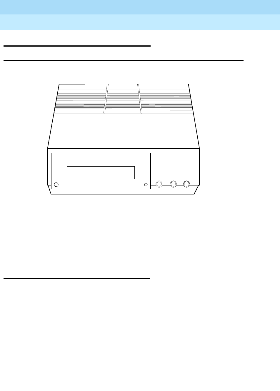
DEFINITYEnterpriseCommunicationsServerandSystem75andSystem85
Terminals and Adjuncts Reference
555-015-201 Issue 11
December 1999
Data Modules
21-31The 7500B Data Module
21
The 7500B Data Module
Figure 21-9. The 7500B Data Module
The 7500B Data Module is a terminal adapter primarily intended for connecting
DTE or DCE to the ISDN network. It can be configured in a number of ways to
allow the attached DTE and DCE to send and receive data through the digital
network. The 7500B has no voice functions.
Applications
The 7500B Data Module can be used with the DEFINITY Communications
System Generic 2 through a 4-wire “T”-interface. It is used by the customer who
wants to connect his DCE and DTE with DTE, DCE, or host processor at another
location using an ISDN network. The 7500B data module cannot be used in a
modem pooling or Host Access arrangement on a DEFINITY G2.
POWER/TEST DATA
PORT
DSR
DCD
RTS
CTS
TD
RD
DTR
ENTER / YESBACKNEXT / NO
HOME
1357 9111315
ISDN
7500

DEFINITYEnterpriseCommunicationsServerandSystem75andSystem85
Terminals and Adjuncts Reference
555-015-201 Issue 11
December 1999
Data Modules
21-32The 7500B Data Module
21
Physical Description
Dimensions
NOTE:
The following dimensions are approximate.
Width = 7 inches
Depth (front and rear) = 8-3/4 inches
Height = 1-3/4 inches
Features
Lights
The 7500B data module has the following light indications:
■POWER/TEST Light — This red light goes on when the 7500B data
module is on and flashes during all tests.
■DATA Light — This green light goes on when a data call is in progress. It
flashes during self-test and when receiving an incoming data call that has
not been answered.
Display
The 16-character LCD display shows the status information and option settings.
NEXT/NO, BACK, and ENTER/YES buttons
These buttons are used to step through each menu, set data communication
options and functions, and adjust the contrast of the display.
Other Physical Features
Jacks
The 7500B data module is equipped with the following jacks.
■LINE — used to connect the 7500B to the ISDN telephone network
■PHONE — (not used)
■POWER — used to connect the 7500B to its DC power supply. The power
supply is connected in turn to a standard AC receptacle.

DEFINITYEnterpriseCommunicationsServerandSystem75andSystem85
Terminals and Adjuncts Reference
555-015-201 Issue 11
December 1999
Data Modules
21-33The 7500B Data Module
21
■COMMUNICATIONS PORT 1 AND 2 — Port 1 is used to connect the
7500B to a data terminal, computer or modem. Depending upon which
enhancement board is installed, port 2 can be used to connect automatic
calling equipment (RS-366 interface) or a data terminal equipment with a
V.35 interface.
Mounting Options
The 7500B data module can be configured as a stand-alone unit or in a
multiple-mount housing.
Color Options
The 7500B data module is available in misty cream only.
Capabilities
Using the available hardware and software options, the 7500B data module can
be configured as an asynchronous DCE or a synchronous DCE. The capabilities
of the different configurations are:
Asynchronous DCE Features
The following data features can be used with the 7500B.
■EIA RS-232D interface
■Circuit switched data communications. Data options can be changed and
data calls can be setup via commands from the EIA-432D interface.
■Ability to change options without dropping a data call
■Automatic or manual answering of incoming data calls
■Data rates of 0.3, 1.2, 2.4, 4.8, 9.6, and 19.2 kbps
■Asynchronous full-duplex operation
■RS-366 Automatic Calling Unit (ACU) interface (requires Multiple
Enhancement Board)
■Hayes AT interface support
Synchronous DCE Features
The synchronous DCE features with the Multipurpose Enhancement Board are as
follows:
■EIA RS-232D interface
■Circuit switched or nailed-up data communication
■Data rates of 1.2, 2.4, 4.8, 9.6, 19.2, 56, and 64 kbps
■Full-duplex operation at all speeds

DEFINITYEnterpriseCommunicationsServerandSystem75andSystem85
Terminals and Adjuncts Reference
555-015-201 Issue 11
December 1999
Data Modules
21-34The 7500B Data Module
21
■Synchronous half-duplex emulation at 1.2 to 56 kbps
■Automatic answering of incoming data calls
■RS-366 ACU interface
■Autodial
The synchronous DCE features with the High Speed Synchronous Enhancement
Board are as follows:
■V. 35 in te rf a ce
■Circuit switched or nailed-up data communication
■Data rates of 48, 56, and 64 kbps
■Full-duplex operation at all speeds
■Synchronous half-duplex emulation at 56 kbps only
■Automatic answering of incoming data calls
■Autodial
Distance Limitations
The maximum signaling distance from the port board to the work location jack
based on DIW 24 AWG cable is:
■Terminating resistor in work location — 1,900 feet
■Terminating resistor in satellite closet — 1,600 feet
Power Requirements
The stand-alone 7500B Data Module operates with power from a modular AC to
DC adapter that is normally plugged into a wall outlet. When the 7500B is used in
a multiple mount arrangement, a built-in power supply is provided in the 77A Data
Mounting.
Terminating Resistor
A 440A4 Terminating Resistor adapter is required with the 7500B. The 440A4 can
be located at the work location or in the satellite closet.
FCC Registration
The 7500B data module is not FCC registered.
Additional Documents
The following documents contain additional information relating to the 7500B Data
Module:
7500B Data Module User’s Manual
, 555-021-717

DEFINITYEnterpriseCommunicationsServerandSystem75andSystem85
Terminals and Adjuncts Reference
555-015-201 Issue 11
December 1999
Data Modules
21-35The ISDN Asynchronous Data Module (ADM)
21
The ISDN Asynchronous
Data Module (ADM)
The ISDN ADM is used in conjunction with an ISDN 7505, 7506, or 7507 voice
terminal to provide integrated voice/data. With the ADM, an attached data
terminal or personal computer can send and receive data through the switch. This
unit mounts in the base of the voice terminal and is used instead of the Voice Only
Module (VOM). The VOM cannot be upgraded to an Asynchronous Data Module.
Physical Description
The following are physical characteristics of the ISDN ADM.
■The ISDN ADM is a printed circuit board built into the ISDN 7505, 7506,
and 7507 Voice Terminal.
■Data and EIA RS-232-D connections — An EIA RS-232-D and an 8-pin
modular jack are located on the back of the ADM.
Features
The ISDN ADM offers the following features:
■Speed — Data rates of 0.3, 1.2, 2.4, 4.8, 9.6, and 19.2 kbps
■Full-duplex
■Asynchronous
■DATA/SEND/OFF button with two indicator lights; allows alternative data
call setup from dial pad
■Data call setup from an ASCII keyboard through an EIA RS-232-D interface
■Ability to change options without dropping the data call
■Automatic or manual answering of incoming calls
■Remote and local loopback test
■Local mode operation for option setting and call control via terminal
keyboard
■Hayes AT interface support

DEFINITYEnterpriseCommunicationsServerandSystem75andSystem85
Terminals and Adjuncts Reference
555-015-201 Issue 11
December 1999
Data Modules
21-36The ISDN Asynchronous Data Module (ADM)
21
Power Requirements
Refer to the Power Requirements description in the ISDN 7505, 7506, and 7507
Voice Terminal section of this manual. (This information is located behind the tab
labeled ISDN Voice Terminals.)
ISDN ADM PECs
Refer to the PEC list in the ISDN 7505, 7506, and 7507 Voice Terminal section of
this manual.
Additional Documents
The following document contains information relating to the ISDN ADM:
■
ISDN Asynchronous Data Module Feature Package 2 User’s Manual
,
555-021-716
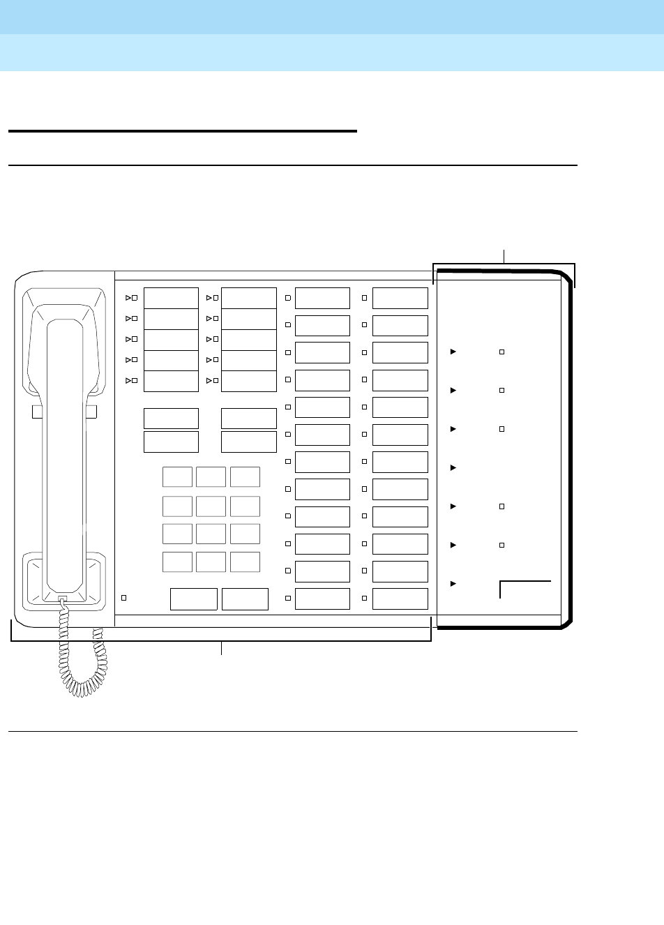
DEFINITYEnterpriseCommunicationsServerandSystem75andSystem85
Terminals and Adjuncts Reference
555-015-201 Issue 11
December 1999
Data Modules
21-37The Digital Terminal Data Module (DTDM)
21
The Digital Terminal
Data Module (DTDM)
Figure 21-10. The Digital Terminal Data Module Mounted on a 7405D Voice Terminal
The DTDM provides a DCE interface to a DTE device that is connected to the
DTDM (see Figure 21-11) and allows the DTE to communicate with the switch
through the voice terminal and its mounting cord. Data calls and voice calls can be
carried on simultaneously, or data calls can be initiated independently of voice
calls. The DTDM and the digital voice terminal integrate data and voice into the
DCP interface with the system digital switch. The voice terminal user can continue
to access all voice features while the module is active on a data call.
123
456
789
ABC DEF
MNOJKLGHI
PRS TUV WXY
*
O#
Oper
Conference
Drop
Transfer
Hold
Message
Disconnect
Recall
192K
9600
4000
2400
1200
300
LOW
TERMINAL
READY
CALL IN
PROGRESS
CARRIER
ON
TEST IN
PROGRESS
CHECK
OPTIONS
DATA CALL
ORIGINATE/
DISCONNECT
Digital Terminal
7405 Voice Terminal
Data Module (DTDM)
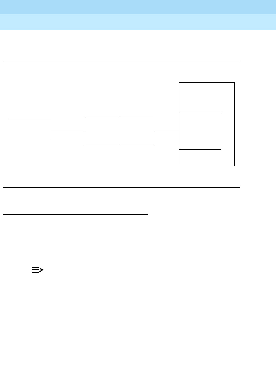
DEFINITYEnterpriseCommunicationsServerandSystem75andSystem85
Terminals and Adjuncts Reference
555-015-201 Issue 11
December 1999
Data Modules
21-38The Digital Terminal Data Module (DTDM)
21
Addition of a DTDM allows an in-place 7403D or 7405D voice terminal to be
upgraded for data communications at low cost.
Figure 21-11. A Block Diagram of DTDM Interfaces
Physical Description
The DTDM is contained in a molded plastic housing styled to match the
associated voice terminal. Status lights, switches, and controls are located on the
faceplate and behind a hinged side cover.
Dimensions
NOTE:
The following dimensions are approximate.
Width = 4-3/4 inches
Depth (front to back) = 8-3/4 inches
Thickness = 1-1/2 inches
Data
Terminal DTDM
Digital Switch
RS-232C
DCE
Digital
Voice
Terminal
DCP Digital
Line
Port
DTE

DEFINITYEnterpriseCommunicationsServerandSystem75andSystem85
Terminals and Adjuncts Reference
555-015-201 Issue 11
December 1999
Data Modules
21-39The Digital Terminal Data Module (DTDM)
21
Features
Lights
The DTDM is equipped with the following lights:
■Terminal Ready
■Call in Progress
■Carrier On
■Test in Progress
■Check options
■Receive Data
■Send data
■Test Re su lt
Speed Indicator lights
The DTDM is equipped with seven indicator lights that show the speed at which
the DTDM is operating.
Switches
The following switches can be used on the DTDM.
■Speed selector switch — The thumbwheel speed selector switch (located
behind the side cover) selects data rates of LOW, 0.3, 1.2, 2.4, 4.8, 9.6, or
19.2 kbps.
■Test switch — The Self-Test and Local Loop/Remote loop switches are
located behind the side cover.
■Option switches — The seven option switches are located behind the side
cover.
■Data Call Switch — The DTDM is equipped with a Data Call Switch labeled
Originate and Disconnect.
Other Physical Features
Mounting Options
The DTDM is physically mounted to a 7403D or 7405D voice terminal. It attaches
to the right side of the voice terminal. The entire unit can be desk or wall mounted
with one exception: if the voice terminal is equipped with a Function Key Module,
Call Coverage Module or Digital Display Module and a DTDM, it cannot be wall
mounted.
Color Options
The DTDM is available only in silver.

DEFINITYEnterpriseCommunicationsServerandSystem75andSystem85
Terminals and Adjuncts Reference
555-015-201 Issue 11
December 1999
Data Modules
21-40The Digital Terminal Data Module (DTDM)
21
Capabilities
The DTDM offers the following features and capabilities:
■Synchronous and asynchronous operation
■Half- and full-duplex operation
■Data transmission at standard rates up to 19.2 kbps
■Automatic answer option
■Self-test
■Remote and local loopback
Power
The DTDM requires auxiliary power from one of the sources listed in the Adjunct
Power section earlier in this manual.
FCC Registration
The DTDM is not FCC registered.
DTDM Equipment PECs
The DTDM can be ordered using the following PECs:
■Digital Terminal Data Module for 7403D—31745MTG05
■Digital Terminal Data Module for 7405D—31745MTG06
■Digital Terminal Data Module for 7405D and Function Key Module—
31745MTG07
■Digital Terminal Data Module for 7405D and Call Coverage Module or
Digital Display Module—31745MTG08
■Digital Terminal Data Module for 7405D and Function Key Module, and Call
Coverage Module or Digital Display Module—31745MTG09
Additional Documents
The following documents contain additional information relating to the DTDM:
■
System 75 and System 85 DTDM User’s Guide
, 999-700-027
■
DEFINITY Generic 1 and Generic 2, System 75, and System 85 Terminals
and Adjuncts Installation and Test
, 555-015-104
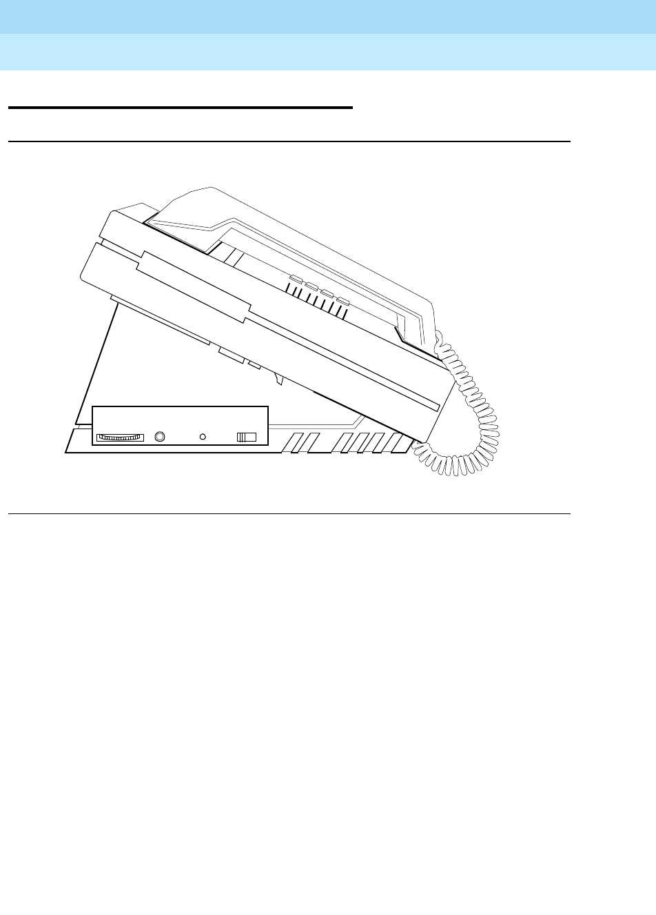
DEFINITYEnterpriseCommunicationsServerandSystem75andSystem85
Terminals and Adjuncts Reference
555-015-201 Issue 11
December 1999
Data Modules
21-41The Z702AL1 Data Service Unit (DSU)
21
The Z702AL1 Data Service Unit (DSU)
Figure 21-12. The Optional Z702AL1 Data Service Unit Shown with
a 7407D01B Voice Terminal
The Z702AL1 DSU, when connected to the 7407D01B voice terminal, allows the
user to transmit and receive voice and data over the same standard two pair of
wires. The DSU provides the RS-232-C connection the data terminal needs to
communicate with other data equipment without separate lines or modems.
(See Figure 21-13.) The DSU supports asynchronous, full duplex operation.
SPEED RESULTS TEST/DISC EVEN-ODD
PARITY
TEST
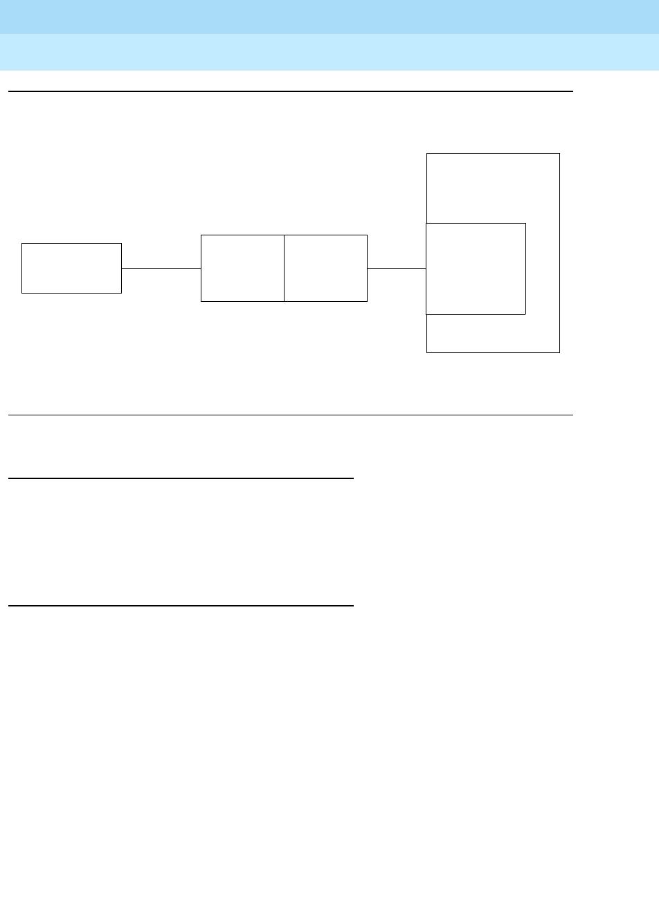
DEFINITYEnterpriseCommunicationsServerandSystem75andSystem85
Terminals and Adjuncts Reference
555-015-201 Issue 11
December 1999
Data Modules
21-42The Z702AL1 Data Service Unit (DSU)
21
Figure 21-13. A Block Diagram of Z702AL1 Data Service Unit Interfaces
Applications
The Z702AL1 DSU can be used with a 7407D01B voice terminal connected to the
DEFINITY Communications System Generic 1, Generic 2, and Generic 3, the
DEFINITY ECS, System 75, and System 85. Typical applications are users with
data terminals requiring a large number of features and lines.
Physical Description
Features
Data Speed wheel
The Data Speed wheel selects the speed of operation. It is located on the right
side of the DSU.
Self-Test light
The Self-Test light is located on the right side of the DSU.
Self-test or disconnect button
The Self-Test or Disconnect button is located on the right side of the DSU.
Parity switch
The parity switch is located on the right side of the DSU.
Data
Terminal
Data
Service
Digital
RS-232C
Unit
DCE
Digital
Voice
Terminal
DCP
Switch
Digital
Line
Port
DTE

DEFINITYEnterpriseCommunicationsServerandSystem75andSystem85
Terminals and Adjuncts Reference
555-015-201 Issue 11
December 1999
Data Modules
21-43The Z702AL1 Data Service Unit (DSU)
21
Other Physical Features
Mounting Options
The optional Z702AL1 DSU Data Module Base is installed on the 7407D01B voice
terminal.
Color Options
The DSU is available in black only.
Capabilities
The Z702AL1 DSU provides the following features:
■Selector for standard data rates of 0.3, 1.2, 2.4, 4.8, 9.6, and 19.2 kbps
■Asynchronous full duplex operation
■Automatic data call answering
■Data terminal keyboard dialing
■Data terminal keyboard disconnect
■Simultaneous voice operation
■Self-Test or Disconnect button
■Data Terminal Equipment (DTE) RS-232-C interface
Power
The Z702AL1 DSU is powered by the 7407D01B which, in turn,
is powered by a 110-volt AC wall receptacle.

DEFINITYEnterpriseCommunicationsServerandSystem75andSystem85
Terminals and Adjuncts Reference
555-015-201 Issue 11
December 1999
Data Modules
21-44The Z702AL1 Data Service Unit (DSU)
21
Z702AL1 DSU PECs
The Z702AL1-DSU can be ordered using the following PEC:
■Z702AL1 DSU—31800A
Additional Documents
The following documents contain additional information relating to the DSU:
■
DEFINITY Generic 2 and System 85 7407D Voice Terminal User’s Guide
,
555-104-705
■
System 85 Application Notes
, 555-102-515
■
System 75 Application Notes
, 555-209-006
■
DEFINITY Generic 1 7407D Voice Terminal User’s Guide
, 555-204-716
■
System 75 7407D Voice Terminal User’s Guide
, 555-200-716
■
DEFINITY Generic 1 and Generic 2, System 75, and System 85 Terminals
and Adjuncts Installation and Test
, 555-015-104
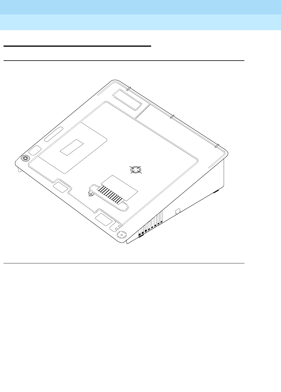
DEFINITYEnterpriseCommunicationsServerandSystem75andSystem85
Terminals and Adjuncts Reference
555-015-201 Issue 11
December 1999
Data Modules
21-45The 703A Data Service Unit (DSU)
21
The 703A Data Service Unit (DSU)
Figure 21-14. The 703A Data Service Unit
The 703A DSU is used with the 7406D voice terminal to provide asynchronous
data communications through the switch. The DSU replaces the desk stand under
the 7406D voice terminal and allows a data terminal (such as a 610 BCT) to be
connected to the 7406D and data calls to be made to and from the switch. (See
Figure 21-15.)
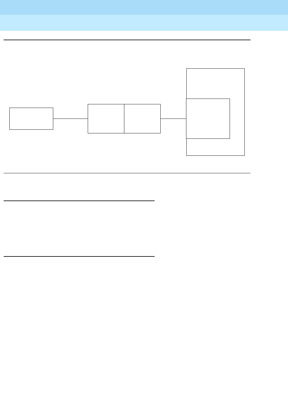
DEFINITYEnterpriseCommunicationsServerandSystem75andSystem85
Terminals and Adjuncts Reference
555-015-201 Issue 11
December 1999
Data Modules
21-46The 703A Data Service Unit (DSU)
21
Figure 21-15. A Block Diagram of 703A Data Service Unit Interfaces
Applications
The 703A DSU can be used with 7406D voice terminal connected to the
DEFINITY Communications System Generic 1, Generic 2, Generic 3, the
DEFINITY ECS, System 75, or System 85. Typical applications are users with
data terminals requiring a large number of features.
Physical Description
Features
Option switches
The option switches for setting the operating speeds, disconnect sequence, and
parity are located on the bottom of the DSU.
Self-Test button
The Self-Test button is located on the rear of the data stand adjacent to the
RS-232-C connector. It is recessed and can be depressed with a pointed object
such as a straightened paper clip.
Data
Terminal
Data
Service
Digital
RS-232C
Unit
DCE
Digital
Voice
Terminal
DCP
Switch
Digital
Line
Port
DTE

DEFINITYEnterpriseCommunicationsServerandSystem75andSystem85
Terminals and Adjuncts Reference
555-015-201 Issue 11
December 1999
Data Modules
21-47The 703A Data Service Unit (DSU)
21
Other Physical Features
Jacks
The DSU contains four jacks. The handset cord jack is on the bottom of the DSU
housing just under the left side of the housing. The mounting cord jack and the
audio cord jack are on the bottom of the DSU housing just under the rear of the
housing. The RS-232-C connector is on the rear of the DSU.
Mounting Options
The optional 703A Data Service Unit Data Module Base is installed on the 7406D
Voice Terminal. When the 7406D is equipped with the DSU, it cannot be wall
mounted.
Color Options
The DSU is available in black only.
Capabilities
The 703A DSU provides the following features and capabilities:
■Selector for standard data rates of 0.3, 1.2, 2.4, 4.8, 9.6, and 19.2 kbps
■Asynchronous full-duplex operation
■Automatic answering of data calls
■Data terminal keyboard dialing
■Parity switch (even / odd)
■Disconnect sequence switch (escape, break)
■Quiet option switch
■Button for self-test and data call disconnect
■Simultaneous voice operation
■Speed matching to a lower speed of remote data endpoint
■Remote loop test (from a distant data module)
■EIA RS-232-C interface
■Appearance of dialed number on the DTE screen (7406D02A only) during
data call setup with the ASCII DTE
■Display features for the 7406D02A on the attached CRT

DEFINITYEnterpriseCommunicationsServerandSystem75andSystem85
Terminals and Adjuncts Reference
555-015-201 Issue 11
December 1999
Data Modules
21-48The 703A Data Service Unit (DSU)
21
Power
The 703A DSU requires an external power source. Refer to the Adjunct Power
section earlier in this manual for the correct power source.
703 DSU PECs
The 703A DSU can be ordered using the following PEC:
■703A Data Stand — 31824A
Additional Documents
The following documents contain additional information relating to the 703A DSU:
■
DEFINITY Generic 2 and System 85 7406D Voice Terminal User’s Guide
,
555-104-702
■
DEFINITY Generic 1 7406D Voice Terminal User’s Guide
, 555-204-719
■
System 75 7406D Voice Terminal User’s Guide
, 555-200-719
■
DEFINITY Generic 1 and Generic 2, System 75, and System 85 Terminals
and Adjuncts Installation and Test
, 555-015-104
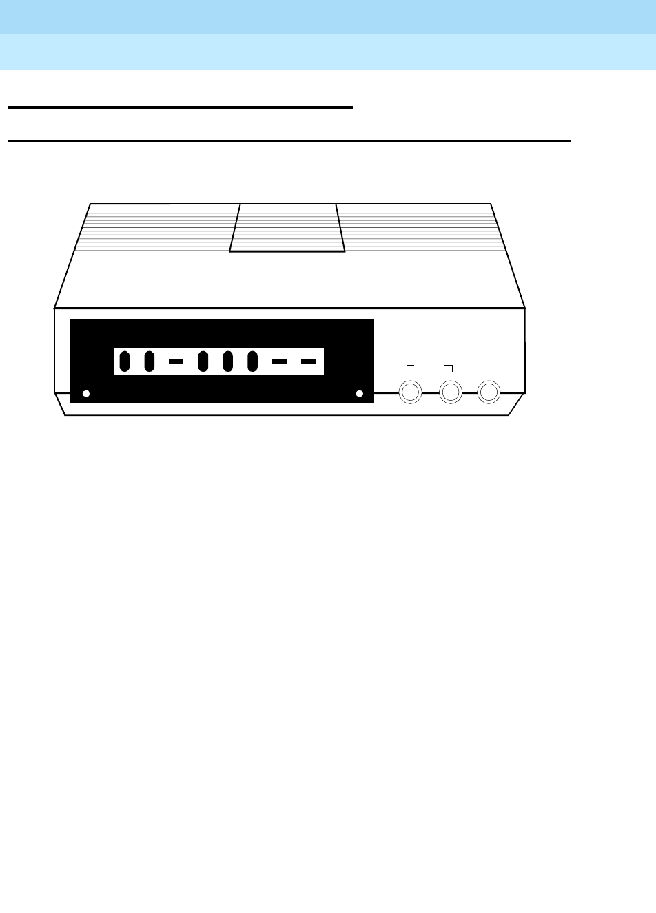
DEFINITYEnterpriseCommunicationsServerandSystem75andSystem85
Terminals and Adjuncts Reference
555-015-201 Issue 11
December 1999
Data Modules
21-49The DEFINITY High Speed Link
21
The DEFINITY High Speed Link
Figure 21-16. The DEFINITY High Speed Link
The DEFINITY HSL is a data service unit that allows data equipment to access
the data services of System 75 and System 85 and the DEFINITY switch. It is
used where the integration of voice and data is not required. The HSL supports
synchronous data transmission at speeds of 56 and 64 kbps, and provides a link
to high speed data networks.
The DEFINITY HSL provides access to various switched and dedicated (private)
data networks, including Group 4 Fax, Video Teleconferencing, LAN Interconnect,
and Cluster Controller/Front-End Processor Connections.
POWER/ DATA
DEFINITY High Speed Link
DTR
RI
DCD
RTS
CTS
TD
RD
DSR
TEST
ENTER / YESBACKNEXT / NO
HOME

DEFINITYEnterpriseCommunicationsServerandSystem75andSystem85
Terminals and Adjuncts Reference
555-015-201 Issue 11
December 1999
Data Modules
21-50The DEFINITY High Speed Link
21
Physical Description
Dimensions
NOTE:
The following dimensions are approximate.
Width = 7 inches
Depth (front and rear) = 9-1/4 inches
Height = 1-3/4 inches
Weight = 1 pound 5 ounces
Features
Lights
The DEFINITY HSL is equipped with the following lights:
■POWER/TEST light — This red light goes on steadily when there is power
to the HSL; winks during all tests; and flashes with the DATA light for line
fault indication.
■DATA light — This green light goes on steadily indicating a data call is in
progress; flashes when receiving an incoming call; and flashes with the
POWER/TEST light for line fault indication.
Display
This 16-character LCD display shows the start-up sequence, status, option
information, and test information.
NEXT/NO, BACK, and ENTER/YES buttons
These buttons are used to step forward and backward through the menus. These
buttons are also used for executing functions.

DEFINITYEnterpriseCommunicationsServerandSystem75andSystem85
Terminals and Adjuncts Reference
555-015-201 Issue 11
December 1999
Data Modules
21-51The DEFINITY High Speed Link
21
Tests
The DEFINITY HSL supports the following tests and maintenance features:
■Self-test
■Local loopback
■Data loopback
■Remote loopback (V.54 and AT&T proprietary protocol)
■Remote loopback with self-test
■DCP looparound test
■DDS latching/non-latching loopback
Connectors
The following connectors are located on the rear panel of the HSL:
■RS-366/RS-232 (user must provide interface cable)
■V.35 (user must provide interface cable)
■LINE (cord shipped with set)
■POWER (for single installations, power is provided by a separately ordered
stand-alone power supply —PEC 21625; for rack mounted installations,
power is included with the Z77A Data Mounting —PEC 21626)
Other Physical Features
Mounting Options
The HSL can be used as a stand-alone unit. It can also be installed in a Z77A
multiple-mount rack.
Color Options
The DEFINITY HSL is available in misty cream only.
Capabilities
The basic features and capabilities of the DEFINITY HSL are:
■DCP operation up to 5,000 feet from the switch
■Supertwist LCD and three push-buttons for displaying status, setting
options, controlling tests, storing telephone numbers, originating and
manually answering calls
■Two LEDs for power, incoming calls, data mode, test mode and fault
indications
■V.35 internally timed, synchronous interface for 56 kbps half duplex
operation, 56 kbps full duplex operation, and 64 kbps full duplex operation

DEFINITYEnterpriseCommunicationsServerandSystem75andSystem85
Terminals and Adjuncts Reference
555-015-201 Issue 11
December 1999
Data Modules
21-52The DEFINITY High Speed Link
21
■RS-366 ACU interface for originating data calls
■RS-232 AT command interface with autobaud for originating and
disconnecting calls
■Test features for system fault isolation
■Non-volatile memory for storing an option profile and four telephone
numbers
■Reset options for easy loading of default options
■Data inversion option for compatibility with older 64 kbps DCP data
modules
■Automatic or manual answer option
■DTR lead ignore option for operation with terminals that normally interface
with private line DCE equipment
■DSR lead ON option for operation with terminals that normally interface
with private line DCE equipment
■Optional DTR lead activated dial feature for stored number dialing
■Permanent connection option for operation in private line applications
■Memory cartridge interface for firmware upgrades
Applications
Administration
The DEFINITY HSL is administered and/or aliased as an MPDM. Routing,
trunking and other administration considerations mirror those of the MPDM. The
uses of the DEFINITY HSL are compatible with those of an MPDM.
Switched Requirements
The following sections describe switched requirements.
Releases for Switched Applications
The switch releases which support the applications of the DEFINITY HSL are:
■System 75 R1V2 or later
■System 85 R2V3 or later
■DEFINITY Generic 1, Generic 2, and Generic 3
■DEFINITY ECS
All versions of the switch do not provide the same level of support. The biggest
difference is in the type of network access arrangement that is supported.
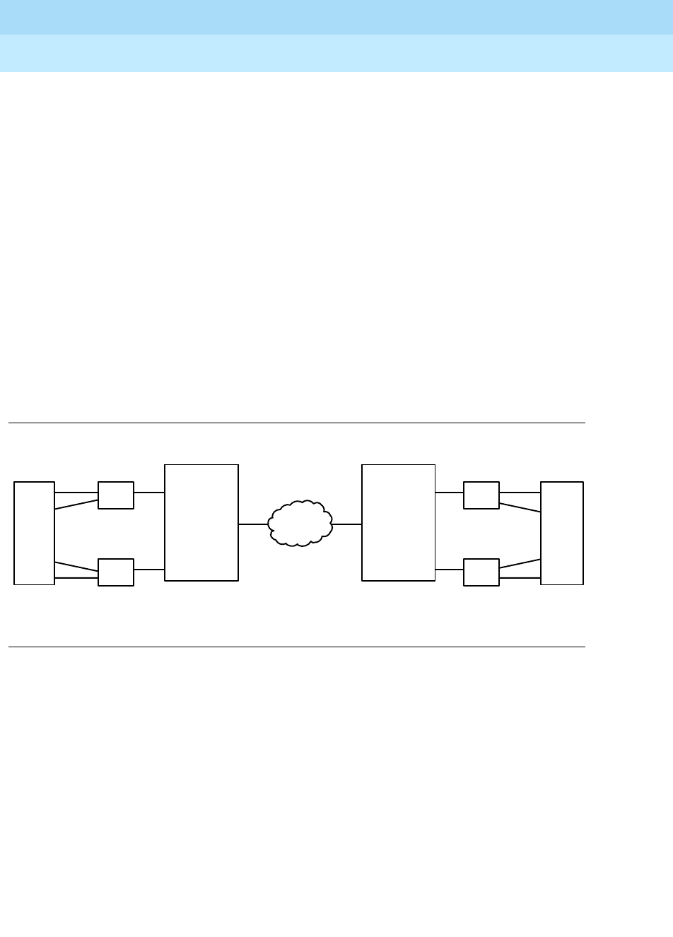
DEFINITYEnterpriseCommunicationsServerandSystem75andSystem85
Terminals and Adjuncts Reference
555-015-201 Issue 11
December 1999
Data Modules
21-53The DEFINITY High Speed Link
21
Switched Endpoints
The DTE must be capable of communicating at 56 kbps or 64 kbps. Proper
switched operation requires that the DTE supports a Data Terminal Ready (DTR)
lead on its V.35 interface. The DTR lead provides the signal to the HSL that it is
ready to receive or originate a call. Before the High Speed Link can originate (dial)
or answer a call, the DTR lead must be asserted (high) by the DTE. In addition,
the DTE uses the DTR lead to signal the HSL to drop a call. This is accomplished
by turning off its DTR lead.
Switched Applications
Switched applications are applications using the switched network. ACCUNET
Switched Digital Services (SDS) and Software Defined Data Network (SDDN) are
examples of switched applications. See Figure 21-17 for an example of a switched
configuration. For additional information on switched applications,
implementations, and administration, refer to the
DEFINITY High Speed Link
User’s Manual
, 555-020-711, Appendix D: Applications and Switch
Administration.
Figure 21-17. Switched Network Application
RS-366
Video
V.35
HSL DCP
HSL DCP
RS-366
V.35
RS-366
V.35
HSL
DCP
HSL
DCP RS-366
V.35
Video
DEFINITY G1 DEFINITY G2
Switched
Network

DEFINITYEnterpriseCommunicationsServerandSystem75andSystem85
Terminals and Adjuncts Reference
555-015-201 Issue 11
December 1999
Data Modules
21-54The DEFINITY High Speed Link
21
Permanent (Private Line) Requirements
The following sections describe Permanent (Private Line) requirements.
Releases for Permanent Applications
Permanent applications require the switch to establish and maintain the
connection. The switch release and corresponding feature that support
permanent connections are:
■System 75 R1V2 or later - Permanent Switched Call (PSC)
■System 85 R2V4 or later - Dedicated Switch Connection (DSC)
■DEFINITY Generic 1 - Administered Connection (AC) or Permanent
Switched Call (PSC)
■DEFINITY Generic 2 - DSC
■DEFINITY Generic 3 and the DEFINITY ECS - AC
These various switch features provide different levels of support for permanent
applications. The DEFINITY G3 and DEFINITY ECS provide the broadest level of
support with the Administered Connection Feature. The Permanent Switch Call in
System 75 and DEFINITY G1 and the Dedicated Switch Connection in System 85
and DEFINITY G2 provide a subset of that functionality.
Permanent Endpoints
If DTE does not support the DTR lead, then the DTR IGNORE option must be
used. This will allow a permanent connection to be established and maintained.
Permanent Applications
A permanent connection uses a DS0 channel on a private T1 between sites, or a
DS0 channel on a DS1 to a private digital network such as ACCUNET Spectrum
of Digital Services (ASDS). See Figure 21-18 for an example of a Front End
Processor/Cluster Controller application in a permanent connection configuration.
For additional information on permanent applications, implementations, and
administration, refer to the
DEFINITY High Speed Link User’s Manual
,
555-020-711, Appendix D: Applications and Switch Administration.
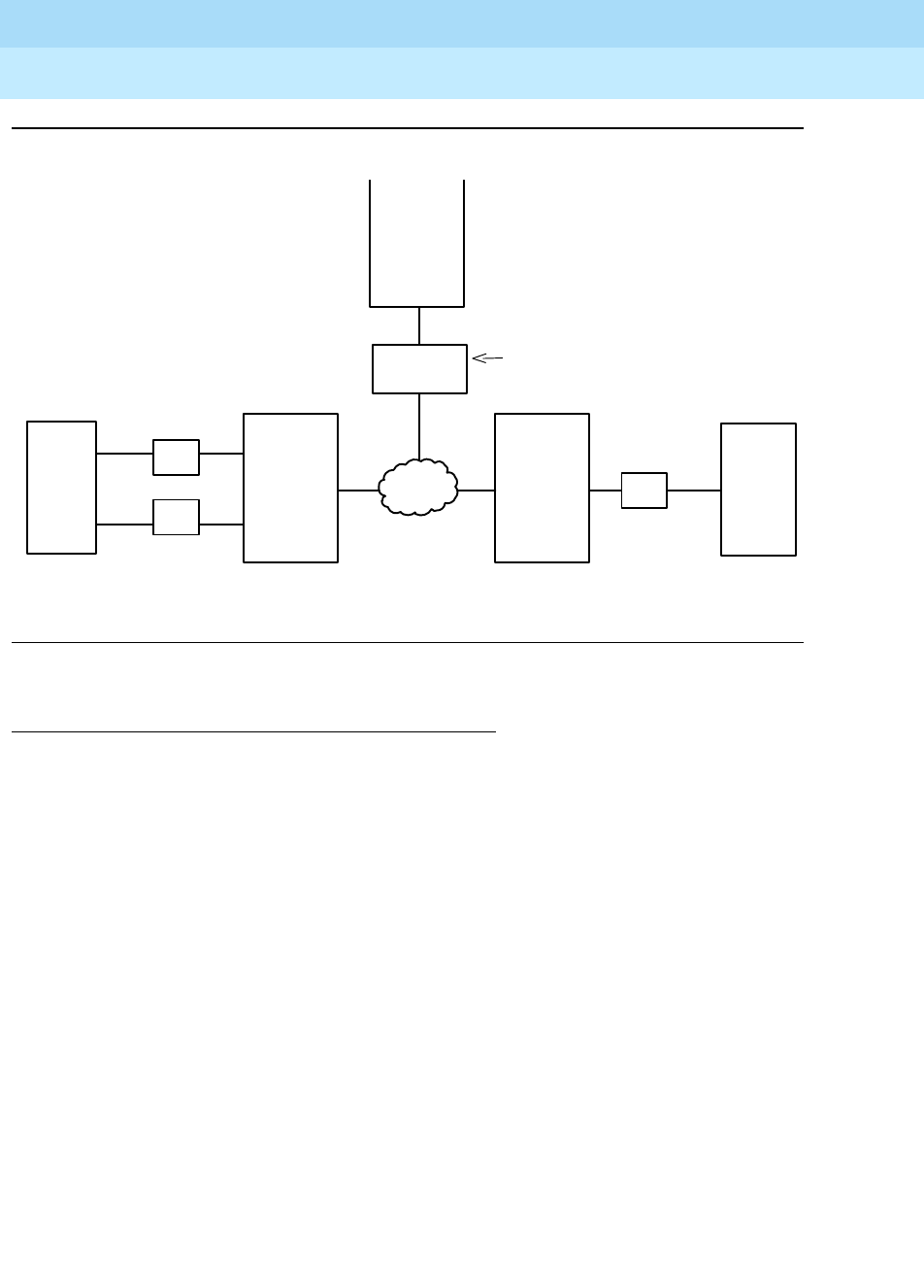
DEFINITYEnterpriseCommunicationsServerandSystem75andSystem85
Terminals and Adjuncts Reference
555-015-201 Issue 11
December 1999
Data Modules
21-55The DEFINITY High Speed Link
21
Figure 21-18. Permanent (Private Line) Applications
Power
The DEFINITY HSL is powered by an external power supply. The connection to
the power supply uses a six position male connector with one pin removed for
polarization.
Power requirements:
■AC Voltage —104 to 129 volts
■Frequency —57 to 63 Hz
■Power Consumption —9 watts
HSL
V.35
V.35
V.35
HSL Cluster
Controller
DEFINITY G3 DEFINITY G2
DSU
Access
Endpoint
Cluster
Controller
V.35
DDS56
HSL
Front
End
Processor
Private
Line
Network
DCP
DCP
DCP

DEFINITYEnterpriseCommunicationsServerandSystem75andSystem85
Terminals and Adjuncts Reference
555-015-201 Issue 11
December 1999
Data Modules
21-56The DEFINITY High Speed Link
21
Considerations
The DEFINITY HSL will not support the following:
■Asynchronous data transmission
■Integrated voice and data
FCC Registration
Digital phones and data modules are not FCC registered. The DEFINITY HSL
meets FCC Part 15 approval, and is labeled as such.
DEFINITY HSL PECs
The DEFINITY HSL can be ordered using the following PECs:
■DEFINITY High Speed Link
PEC 2161-201
Comcode: 106654478
■Stand-alone Power Supply —PEC 21625
■Z77A Data Mounting (rack with power for up to 8 HSL units)
PEC 21626, Attribute 1— Z77A with WP90780L2 digital line
installation harness
PEC 21626, Attribute 6 —Z77A only
Additional Documents
The following document contains additional information relating to the
DEFINITY HSL:
■
DEFINITY High Speed Link User’s Manual
, 555-020-711
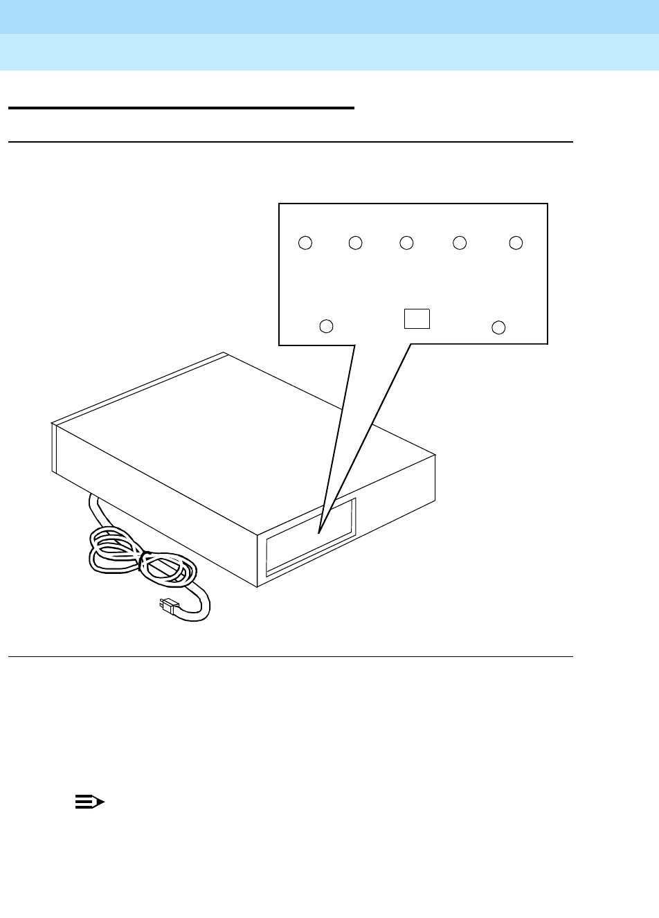
DEFINITYEnterpriseCommunicationsServerandSystem75andSystem85
Terminals and Adjuncts Reference
555-015-201 Issue 11
December 1999
Data Modules
21-57The Processor Data Module (PDM)
21
The Processor Data Module (PDM)
Figure 21-19. The Processor Data Module, the Stand-alone Model
The PDM provides a DCE interface for connection to data terminals, Station
Message Detail Recording (SMDR) output device, on-premises administration
terminal, Applications Processor (AP), Call Management System (CMS), Property
Management System (PMS), Audio Information Exchange (AUDIX), and host
computers. It also provides a DCP interface for connection to the digital switch.
NOTE:
The PDM can no longer be ordered. It has been replaced by the MPDM.
POWER
TEST IN
LINE
PDM
CHECK
OPTIONS
CALL IN
PROGRESS CARRIER
ONSTATUS
PROGRESS
TERMINAL
READY
ORIGINATE
DISCONNECT

DEFINITYEnterpriseCommunicationsServerandSystem75andSystem85
Terminals and Adjuncts Reference
555-015-201 Issue 11
December 1999
Data Modules
21-58The Processor Data Module (PDM)
21
Physical Description
Features
Switches
The PDM is equipped with the following switches:
■Originate/Disconnect — This switch is located on the front panel. It is used
when originating and disconnecting from a call.
■Self-Test — This switch is located behind the front faceplate. Pressing this
button performs the self-test.
■LOC LOOP/REM LOOP — This switch is located behind the faceplate. It is
used to perform the Local loop test or Remote loop test.
■Options — The option switches are located behind the front faceplate.
There are 30 option switches, 25 for options, and 5 spares.
Lights
The PDM is equipped with the following lights:
■Power
■Terminal Ready
■Line Status
■Call in Progress
■Carrier on
■Test in Progress
■Check option
■Test Re su lt
■Send Data
■Receive Data
Other Physical Features
Mounting Options
The PDM can be configured either in a stand-alone or multiple mounted version.
The stand-alone version is installed in a 70A Data Mounting aluminum housing
that is equipped with plastic front and rear covers. A maximum of eight PDM’s can
be installed in the 71A Data Mounting.
The stand-alone version can be mounted on a surface or desk top near the
associated data terminal. The multiple mount is normally contained in an auxiliary
cabinet.

DEFINITYEnterpriseCommunicationsServerandSystem75andSystem85
Terminals and Adjuncts Reference
555-015-201 Issue 11
December 1999
Data Modules
21-59The Processor Data Module (PDM)
21
Capabilities
The PDM offers the following features:
■Synchronous or asynchronous operation
■Full- or half-duplex operation for data calls up to 56 kbps
■Full-duplex operation for data calls at 64 kbps
■Data transmission at standard rates up to 19.2 kbps
■Automatic answer option
■Self-test
Power
Both mounting arrangements require power from a 115-volt AC receptacle to
power the PDM(s).
PDM Equipment PECs
The PDM cannot be ordered; therefore, no PEC is available.
Additional Documents
The following documents contain additional information relating to the PDM:
■
Processor Data Module User’s Guide
, 999-700-028
■
DEFINITY Generic 1 and Generic 2, System 75, and System 85 Terminals
and Adjuncts Installation and Test
, 555-015-104
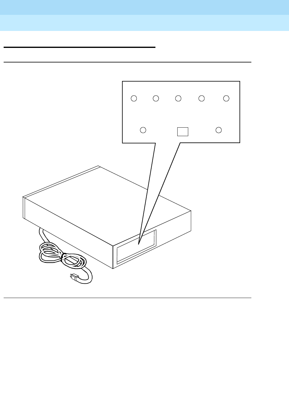
DEFINITYEnterpriseCommunicationsServerandSystem75andSystem85
Terminals and Adjuncts Reference
555-015-201 Issue 11
December 1999
Data Modules
21-60The Trunk Data Module (TDM)
21
The Trunk Data Module (TDM)
Figure 21-20. The Trunk Data Module, the Stand-alone Model
The TDM provides an RS-232-C DTE interface for connection to off-premises
private line trunk facilities or a switched network telecommunications network and
a DCP interface for connection to the digital switch.
POWER
TEST IN
CALL IN
TRUNK DATA MODULE
CHECK
OPTIONS
LINE
STATUS CARRIER
ONPROGRESS
PROGRESS
DATA SET
READY
ORIGINATE
DISCONNECT

DEFINITYEnterpriseCommunicationsServerandSystem75andSystem85
Terminals and Adjuncts Reference
555-015-201 Issue 11
December 1999
Data Modules
21-61The Trunk Data Module (TDM)
21
The TDM can serve as part of a conversion resource for modem pooling. The
conversion resource performs the analog-to-digital and digital-to-analog
conversions that allow the analog and DCP data endpoints to communicate. A
single conversion resource consists of a modem and a TDM connected at the
RS-232-C interface.
NOTE:
The TDM can no longer be ordered. It has been replaced by the MTDM.
Physical Description
Features
Switches
The TDM is equipped with the following switches:
■Originate/Disconnect — This switch is located on the front panel. It is used
when originating and disconnecting from a call for test purposes.
■Self-Test — This switch is located behind the front faceplate. Pressing this
button performs the self-test.
■LOC LOOP/REM LOOP — This switch is located behind the faceplate. It is
used to perform the Local loop test or Remote loop test.
■Options — The option switches are located behind the front faceplate.
There are 30 option switches, 24 for options, and 6 spares.
Lights
The TDM is equipped with the following lights:
■Power
■Data Set Ready
■Line Status
■Call in Progress
■Carrier on
■Test in Progress
■Check option
■Test Re su lt
■Send Data
■Receive Data

DEFINITYEnterpriseCommunicationsServerandSystem75andSystem85
Terminals and Adjuncts Reference
555-015-201 Issue 11
December 1999
Data Modules
21-62The Trunk Data Module (TDM)
21
Other Physical Features
Capabilities
The TDM offers the following features and capabilities:
■Synchronous or asynchronous operation
■Full- or half-duplex
■Selected standard data rates up to 19.2 kbps
■Automatic answer
■Self-test
Mounting Options
The TDM can be configured either in a stand-alone or in a multiple mounted
version. The stand-alone version is installed in a 70A Data Mounting aluminum
housing that is equipped with plastic front and rear covers. A maximum of eight
TDMs may be installed in the 71A Data Mounting.
The stand-alone version can be mounted on a surface or desk top near the
associated data equipment. The multiple-mounting carrier unit is normally
installed in an auxiliary cabinet.
Power
Both mounting arrangements require power from a 115-volt AC receptacle to
power the TDM.
TDM Equipment PECs
The TDM is no longer orderable; therefore, no PEC is available.
Additional Documents
The following documents contain additional information relating to the PDM:
■
Trunk Data Module User’s Guide
, 999-700-029
■
DEFINITY Generic 1 and Generic 2, System 75, and System 85 Terminals
and Adjuncts Installation and Test
, 555-015-104
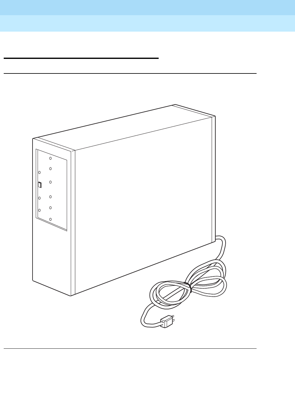
DEFINITYEnterpriseCommunicationsServerandSystem75andSystem85
Terminals and Adjuncts Reference
555-015-201 Issue 11
December 1999
Data Modules
21-63The Modular Processor Data Module (MPDM)
21
The Modular Processor Data Module
(MPDM)
Figure 21-21. The Stand-Alone Modular Processor Data Module
The MPDM is a multi-purpose data module configured to provide the digital switch
interface to support various data interface requirements. The MPDM is similar in
appearance and function to the PDM.
TEST IN PROGRESS
ORIG/
DISC
SEND DATA
RECEIVE DATA
MPDM
ACCUNET®
POWER
TERMINAL
READY
LINE
STATUS
CHECK
OPTIONS
CALL IN
PROGRESS
CARRIER
ON

DEFINITYEnterpriseCommunicationsServerandSystem75andSystem85
Terminals and Adjuncts Reference
555-015-201 Issue 11
December 1999
Data Modules
21-64The Modular Processor Data Module (MPDM)
21
The MPDM can be configured to support the Data Call Setup or Off-Premises
Data-Only Extensions features. In addition to standard data transmission rates
supported by previous versions of the PDM’s (0.3, 1.2, 2.4, 4.8, 9.6, and
19.2 kbps), the MPDM supports data rates of 56 and 64 kbps.
The individual piece parts for the MPDM can be purchased either separately or in
one of the three different preassembled packages described below.
■AUDIX/CMS MPDM
This MPDM package provides connectivity from either Lucent
Technologies AUDIX or CMS to the DCIU link of the DEFINITY
Communications System Generic 1, Generic 2, and Generic 3, the
DEFINITY ECS, System 75, and System 85. The AUDIX/CMS MPDM
supports any endpoint that requires low speed (below 19.2 kbps)
synchronous connectivity.
■The Video Teleconferencing MPDM
This MPDM package allows high speed data endpoints to be switched
through the DEFINITY G1, G2, and G3, the DEFINITY ECS, System 75,
and System 85, to high speed public or private networks. The Video
Teleconferencing MPDM supports an RS-366 Automatic Calling Unit (ACU)
interface to permit dialing through the endpoint (for example, a Video
Teleconference unit or Group 4 FAX machine).
In addition to the RS-366 interface, the Video Teleconferencing MPDM also
uses the ACCUNET D-Kit which allows transmissions over 56 kbps and 64
kbps facilities such as ACCUNET Switched Digital Service. (ACCUNET
Switched 56 kbps Digital Service is an end-to-end switched digital service
accessed by the switch through a DS-1 interface.)
■The High Speed Synchronous MPDM
This MPDM package is designed to support high-speed data applications
that do not require the use of an RS-366 ACU interface (for example,
nailed-up or dedicated calls such as Cluster Controller to Front End
Processor). With the addition of an optional interface card, the High Speed
Synchronous MPDM supports connections over switched or private
networks through System 75, System 85, and a DEFINITY G1 and G2.
NOTE:
All three MPDM preassembled packages use the same housing and main
circuit card. The distinguishing components are, therefore, the interface
cards that each uses.

DEFINITYEnterpriseCommunicationsServerandSystem75andSystem85
Terminals and Adjuncts Reference
555-015-201 Issue 11
December 1999
Data Modules
21-65The Modular Processor Data Module (MPDM)
21
General Features of the MPDM
Both the MPDM stand-alone and multiple mount versions are contained in a
70A Data Mounting aluminum housing that is equipped with plastic front and rear
covers.
The MPDM, in general, offers the following data features:
■Selecteddataratesupto64kbps
■Synchronous or asynchronous operation
■Synchronous operation at 56 kbps and 64 kbps
■Full- or half-duplex operation up to 56 kbps
■Full-duplex operation at 64 kbps
■Automatic answer option
■ACCUNET digital service interface support
■Local Area Network (LAN) bridging: Token Rings, Ethernet, AppleLan
Functional elements
■The Main module comes in one version that is common to all of the MPDM
packages and provides the basic digital interface and protocol conversion
functions.
■The Interface module comes in three versions providing a choice of V.35,
RS-232-C, or RS-449 interfaces (balanced--RS-422A electrical interface).
■The ACU module comes in one optional version. The ACU module
interface provides the capability to emulate an ACU and supports the
RS-366 interface. This module is required for the data terminal dialing
function of the Data Call Setup feature.
Mounting
The MPDM can be configured either in a stand-alone or in a multiple mount
version. A maximum of eight MPDMs can be installed in the 71A Data Mounting.
The stand-alone version can be mounted on a surface or desk top near the
associated data equipment. The multiple-mounting carrier unit is normally
installed in an auxiliary cabinet.
Power
Both mounting arrangements require power from a 115-volt AC receptacle to
power the MPDM(s).

DEFINITYEnterpriseCommunicationsServerandSystem75andSystem85
Terminals and Adjuncts Reference
555-015-201 Issue 11
December 1999
Data Modules
21-66The Modular Processor Data Module (MPDM)
21
Switches
The MPDM is equipped with the following switches:
■ORIGINATE/DISCONNECT — This switch is located on the front panel. It
is used when originating and disconnecting a call from a terminal that does
not have a BREAK key.
■SELF-TEST — This switch is located behind the front faceplate. It is used
to perform the self-test.
■LOC LOOP/REM LOOP — This switch is located behind the faceplate. It is
used to perform the Local loop test or Remote loop test.
NOTE:
If you are using the Video Teleconferencing MPDM or the High Speed
Synchronous MPDM preassembled package, and the OFF/ANET switch is
set to ANET), the user-activated Remote Loop will not function since
Remote Loop requires Mode 2 handshake operation.
■Options — The option switches are located behind the front faceplate.
There are two Dual In-line Package (DIP) option switches, one with
10 positions, the other with 12 positions. Twenty-one of the positions are
used to set the options. The other is a spare reserved for future use.
The RS-232-C interface card has eight DIP switches to set its options.
Lights
The MPDM is equipped with the following lights:
■Power
■Terminal Ready
■Line Status
■Call in Progress
■Carrier on
■Test in Progress
■Check option
■Test Re su lt
■Send Data
■Receive Data
DEFINITYEnterpriseCommunicationsServerandSystem75andSystem85
Terminals and Adjuncts Reference
555-015-201 Issue 11
December 1999
Data Modules
21-67The Modular Processor Data Module (MPDM)
21
Features of the AUDIX/CMS MPDM Package
Functional Elements
This preassembled package consists of the following parts:
■Stand-alone housing
■Modular PDM
■RS-232 interface card
■Option Switch Settings
Since the AUDIX/CMS MPDM is preassembled, you will need only to make the
connections to the PBX, and set the DIP switches. Use the following table to verify
that the DIP switch settings connected to AUDIX or CMS are correctly set.
Table 21-2. DIP Switch Settings on the AUDIX/CMS MPDM
DIP Switch Setting
OFF/LOW OFF
OFF/300 OFF
OFF/1200 OFF
OFF/2400 OFF
OFF/4800 OFF
OFF/9600 9600
OFF/19.2 OFF
OFF/56K OFF
OFF/64K OFF
OFF/TRBK OFF
FDX/HDX FDX
ASYN/SYNC SYNC
EXT/INT INT
OFF/DISC OFF
OFF/KYBD OFF
OFF/PRTY OFF
O/EV-I/OD ignored
OFF/DMLL OFF
OFF/MKBY OFF
Spare OFF
OFF/SIGLS SIGLS
OFF/AANS AANS

DEFINITYEnterpriseCommunicationsServerandSystem75andSystem85
Terminals and Adjuncts Reference
555-015-201 Issue 11
December 1999
Data Modules
21-68The Modular Processor Data Module (MPDM)
21
Features of the Video Teleconferencing MPDM
Functional Elements
The preassembled Video Teleconferencing MPDM consists of the following parts:.
■Stand-alone housing
■Modular PDM
■V.35 interface card
■RS-366 ACU interface card
■V.35 M1 (ACCUNET D-Kit)
NOTE:
The label on the front of this MPDM renames the data module from “MPDM”
to “MPDM ACCUNET.”
Option Settings
The Video Teleconferencing MPDM offers a new option switch, OFF/ANET.
■If this switch is set to OFF, the MPDM/ACCUNET functions as a standard
MPDM.
■If this switch is set to ANET, the Video Teleconferencing MPDM can be
optioned for compatibility with ACCUNET Switched 56 kbps Digital Service
or non-MPDM endpoints such as a DSU. In this mode:
— No Mode 2 handshaking is required to go into data mode
— Keyboard dialing is not supported
— User activated remote loopback test is not supported
The baud rate depends on the setting of the speed option switches. When using
ACCUNET Switched 56 kbps Digital Service, the OFF/56K must be set to 56K. All
other speed switches must be set to OFF.
NOTE:
Only one speed selection is allowed when the OFF/ANET switch is set to
ANET.

DEFINITYEnterpriseCommunicationsServerandSystem75andSystem85
Terminals and Adjuncts Reference
555-015-201 Issue 11
December 1999
Data Modules
21-69The Modular Processor Data Module (MPDM)
21
The Video Teleconferencing MPDM requires the following DIP switch settings for
operation with ACCUNET Switched 56 kbps Digital Service or non-MPDM
endpoints.
Table 21-3. DIP Switch Settings on the Video Teleconferencing MPDM
DIP Switch Setting
OFF/LOW OFF
OFF/300 OFF
OFF/1200 OFF
OFF/2400 OFF
OFF/4800 OFF
OFF/9600 OFF
OFF/19.2 OFF
OFF/56K 56K*
* Must be set at either 56K or 64K.
OFF/64K 64K*
OFF/TRBK OFF
FDX/HDX FDX
ASYN/SYNC SYNC
EXT/INT INT
OFF/DISC OFF
OFF/KYBD OFF
OFF/PRTY OFF
O/EV-I/OD ignored
OFF/DMLL OFF†
† Must be set as appropriate for the installation.
OFF/MKBY OFF†
OFF/ANET ANET
OFF/SIGLS OFF
OFF/AANS AANS†

DEFINITYEnterpriseCommunicationsServerandSystem75andSystem85
Terminals and Adjuncts Reference
555-015-201 Issue 11
December 1999
Data Modules
21-70The Modular Processor Data Module (MPDM)
21
Features of the High Speed Synchronous MPDM
Optional Interface Cards
There are two optional interface cards can be used with this MPDM package:
■V.3 5
— Normal DTR operation
— Endpoint controls (asserts) the DTR lead
■V.35 DTR
— DTR lead on the MPDM is always high
— Endpoint has no control over the DTR lead
— Call is typically under PBX control, for example, permanent switched
call (a DEFINITY G1 and G3) or dedicated switched call (a
DEFINITY G2)
Functional Elements
The preassembled High Speed Synchronous MPDM consists of the following
parts:
■Stand-alone housing
■Modular PDM
■V.35 M1 * (ACCUNET D-Kit)
NOTE:
On the front panel the data module is renamed from “MPDM” to “MPDM
ACCUNET.”
Optional Settings
A new option switch, OFF/ANET, has been added, allowing the High Speed
Synchronous MPDM to be optioned in two different ways:
■When the OFF/ANET switch is set to OFF, this MPDM can be optioned to
function as a standard MPDM
■When the OFF/ANET switch is set to ANET, this MPDM can be optioned to
be compatible with ACCUNET Switched 56 kbps Digital Service. (Set
OFF/ANET to ANET for Dedicated Switch Call [DSC] arrangements.)
— No Mode 2 handshaking required to go into data mode
— Keyboard dialing is not supported
— Remote loopback test is not supported

DEFINITYEnterpriseCommunicationsServerandSystem75andSystem85
Terminals and Adjuncts Reference
555-015-201 Issue 11
December 1999
Data Modules
21-71The Modular Processor Data Module (MPDM)
21
The baud rate depends on the setting of the speed option switches. When using
ACCUNET Switched 56 kbps Digital Service, OFF/56K must be set to 56K. All
other speed switches must be set to OFF.
NOTE:
Only one speed selection is allowed when the OFF/ANET switch is set to
ANET.
When FDX/HDX is set to HDX (half-duplex), it can be used only on a 64 kbps
facility, such as alternate voice/data trunk, PRI facility, or switched-64. (The speed
can be set to 56 kbps, but requires a 64 kbps facility for proper HDX operation.)
REM/LOOP does not function when the OFF/ANET switch is set to ANET since
Remote Loop requires Mode 2 handshake operation.
MPDM PECs and Comcodes
The preassembled MPDM(s) can be ordered with the following PECs and
Comcodes:
■AUDIX/CMS MPDM
PEC: 2161-101
Comcode: 106504574
■Video Teleconferencing MPDM
PEC: 2161-102
Comcode: 106504582
■High Speed Synchronous MPDM
PEC: 2161-103
Comcode: 106504590
The MPDM parts can be ordered using the following PECs and Comcodes:
■Modular MPDM main circuit card
PEC: 2161-PDM
Comcode: 103954541
■Stand-alone housing
PEC: 21702
Comcode: 103954863
■RS-232C interface card
PEC: 21611
Comcode: 103954558
■RS-449 interface card
PEC: 21612
Comcode: 103954566
■V.35 interface card
PEC: 21613
Comcode: 103954574

DEFINITYEnterpriseCommunicationsServerandSystem75andSystem85
Terminals and Adjuncts Reference
555-015-201 Issue 11
December 1999
Data Modules
21-72The Modular Processor Data Module (MPDM)
21
■RS-366 ACU interface card
PEC: 21614
Comcode: 103954582
■V.35 DTR interface card (This card has DTR always on.)
PEC: 21615
Comcode: 105218101
■V.35 M1 * ACCUNET D-Kit (used to support communications over
DS1-robbed bit and ACCUNET facilities)
PEC: 21616
Comcode: 105040141
■71A multiple mounting
PEC: 21711
Comcode: 103872149
Additional Documents
The following documents contain additional information relating to the MPDM:
■
Modular Processor Data Module User’s Guide
, 999-700-300IS
■
DEFINITY Communications System Generic 1 and Generic 2, System 75,
and System 85 Terminals and Adjuncts Installation and Test
, 555-015-104
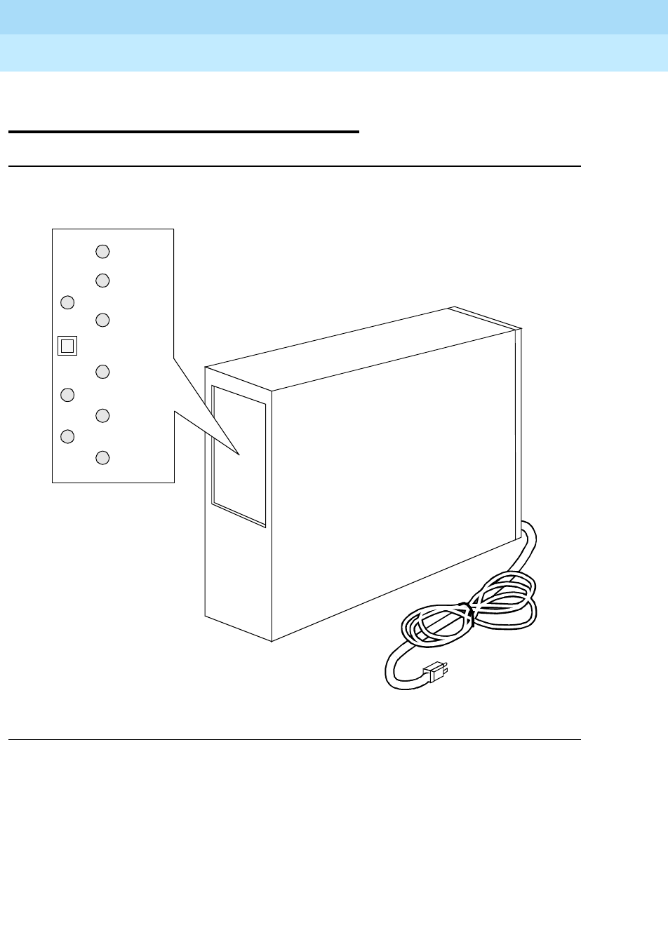
DEFINITYEnterpriseCommunicationsServerandSystem75andSystem85
Terminals and Adjuncts Reference
555-015-201 Issue 11
December 1999
Data Modules
21-73The Modular Trunk Data Module (MTDM)
21
The Modular Trunk Data Module
(MTDM)
Figure 21-22. The Modular Trunk Data Module, the Stand-alone Model
Similar in appearance and function to the TDM, the MTDM is a multi-purpose data
module configured to provide the digital switch interface to off-premises private
line trunk facilities or a switch network telecommunications network. Similar in
appearance and function to the TDM, the MTDM is a multi-purpose data module
configured to provide the digital switch interface to off-premises private line trunk
facilities or a switched network telecommunications network. The MTDM may also
serve as a conversion resource for modem pooling.
POWER
DATA SET
READY
TEST IN PROGRESS
LINE STATUS
ORIG/
DISC MTDM
CHECK
OPTIONS
RECEIVE DATA
CALL IN
PROGRESS
SEND DATA
CARRIER ON

DEFINITYEnterpriseCommunicationsServerandSystem75andSystem85
Terminals and Adjuncts Reference
555-015-201 Issue 11
December 1999
Data Modules
21-74The Modular Trunk Data Module (MTDM)
21
The MTDM can be configured to support the Data Call Setup, Modem Pooling, or
Off-Premises Data-Only Extensions features. In addition to the standard data
transmission rates supported by previous versions of the TDM (0.3, 1.2, 2.4, 4.8,
9.6, and 19.2 kbps), the MTDM supports data rates of 56 and 64 kbps for
downloading and other high speed data transfer requirements.
Physical Description
Features
Functional elements
■Main module — Comes in one version that is common to all modular
modules and provides the basic digital interface and protocol conversion
functions.
■Interface module — Provides an RS-232-C interface
Switches
The MTDM is equipped with the following switches:
■ORIG/DISC — This switch is located on the front panel. It is used when
originating and disconnecting from a call for test purposes.
■Self-Test — This switch is located behind the front faceplate. Pressing this
button performs the self-test.
■LOC LOOP/REM LOOP — This switch is located behind the faceplate. It is
used to perform the Local loop test or Remote loop test.
■Options — The option switches are located behind the front faceplate.
There are two Dual In-line Package switches, one a 10-position, the other a
12-position, located behind the front faceplate. Nineteen of the switches
are used to set the options. The other three are spares reserved for future
use.
Lights
The MTDM is equipped with the following lights:
■Power
■Data Set Ready
■Line Status
■Call in Progress
■Carrier on
■Test in Progress
■Check option
■Test Re su lt

DEFINITYEnterpriseCommunicationsServerandSystem75andSystem85
Terminals and Adjuncts Reference
555-015-201 Issue 11
December 1999
Data Modules
21-75The Modular Trunk Data Module (MTDM)
21
■Send Data
■Receive Data
Other Physical Features
Mounting Options
The MTDM can be configured either in a stand-alone or a multiple mounted
version. The stand-alone version is contained in a 70A Data Mounting aluminum
housing that is equipped with plastic front and rear covers. A maximum of eight
MTDMs may be installed in the 71A Data Mounting.
The stand-alone version can be mounted on a surface or desk top near the
associated data equipment. The multiple-mounting carrier unit is normally
installed in an auxiliary cabinet.
Capabilities
The MTDM offers the following features and capabilities:
■Selectedratesupto64kbps
■Asynchronous rates up to 19.2 kbps
■Synchronous operation at 56 kbps and 64 kbps
■Full- or half-duplex operation up to 56 kbps
■Full-duplex at 64 kbps
■Self-test
■Automatic answer
■Private line and switched modes
Power
Both mounting arrangements require power from a 115-volt AC receptacle to
power the MTDM.
MTDM Equipment PECs
The MTDM can be ordered using the following PECs:
■MTDM — 2162TDM
■RS232C Interface card — 21621
■Stand-alone housing — 21702
■71A Multiple mount — 21711

DEFINITYEnterpriseCommunicationsServerandSystem75andSystem85
Terminals and Adjuncts Reference
555-015-201 Issue 11
December 1999
Data Modules
21-76The Modular Trunk Data Module (MTDM)
21
Additional Documents
The following documents contain additional information relating to the MTDM:
■
Modular Trunk Data Module User’s Guide
, 999-700-301
■
DEFINITY Generic 1 and Generic 2, System 75, and System 85 Terminals
and Adjuncts Installation and Test
, 555-015-104
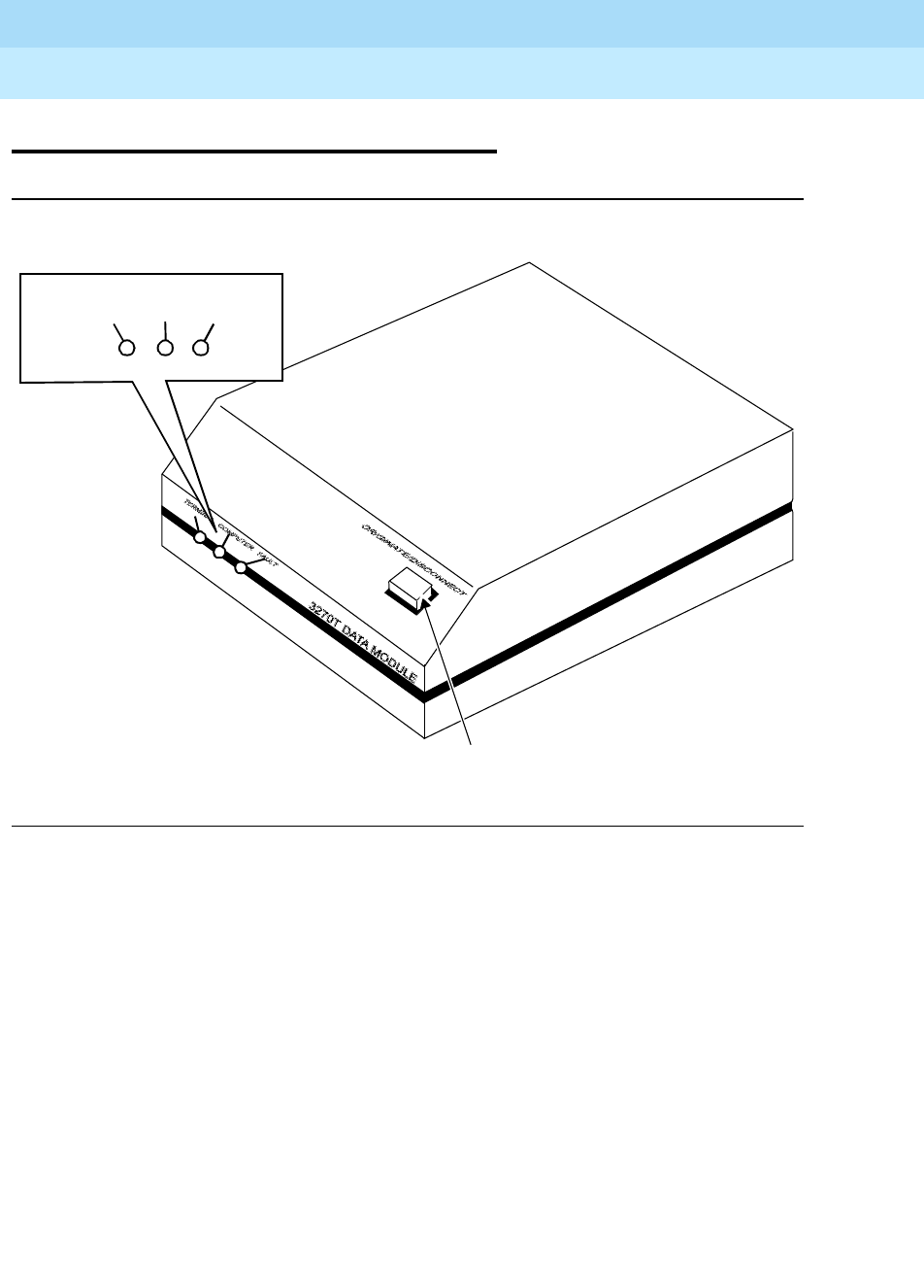
DEFINITYEnterpriseCommunicationsServerandSystem75andSystem85
Terminals and Adjuncts Reference
555-015-201 Issue 11
December 1999
Data Modules
21-77The 3270 Data Module
21
The 3270 Data Module
Figure 21-23. The 3270A or 3270T Data Module
The 3270 Data Module provides a Category A coaxial DCE interface for
connection to 3270-type data terminals or a cluster controller. It also provides a
DCP interface for connection to the digital switch.
The 3270 Data Module is available in the following three models:
■3270T (Terminal) — Connects to a Category A 3270-type terminal, such as
the IBM 3278 Information Delivery System. The 3270T Data Module must
connect through the switch to a 3270C (Controller) Data Module.
■3270A (Asynchronous) — Provides the same function as the 3270T Data
Module. It also allows the 3270-type terminal to emulate a DEC VT100 or
Lucent Technologies’ asynchronous terminal.
■3270C (Controller) — Connects an IBM 3274 or 3276 cluster controller to
the switch. A 3270C Data Module (See Figure 21-24) can contain as many
as eight ports.
TERMINAL FAULTCOMPUTER
Originate/Disconnect Switch
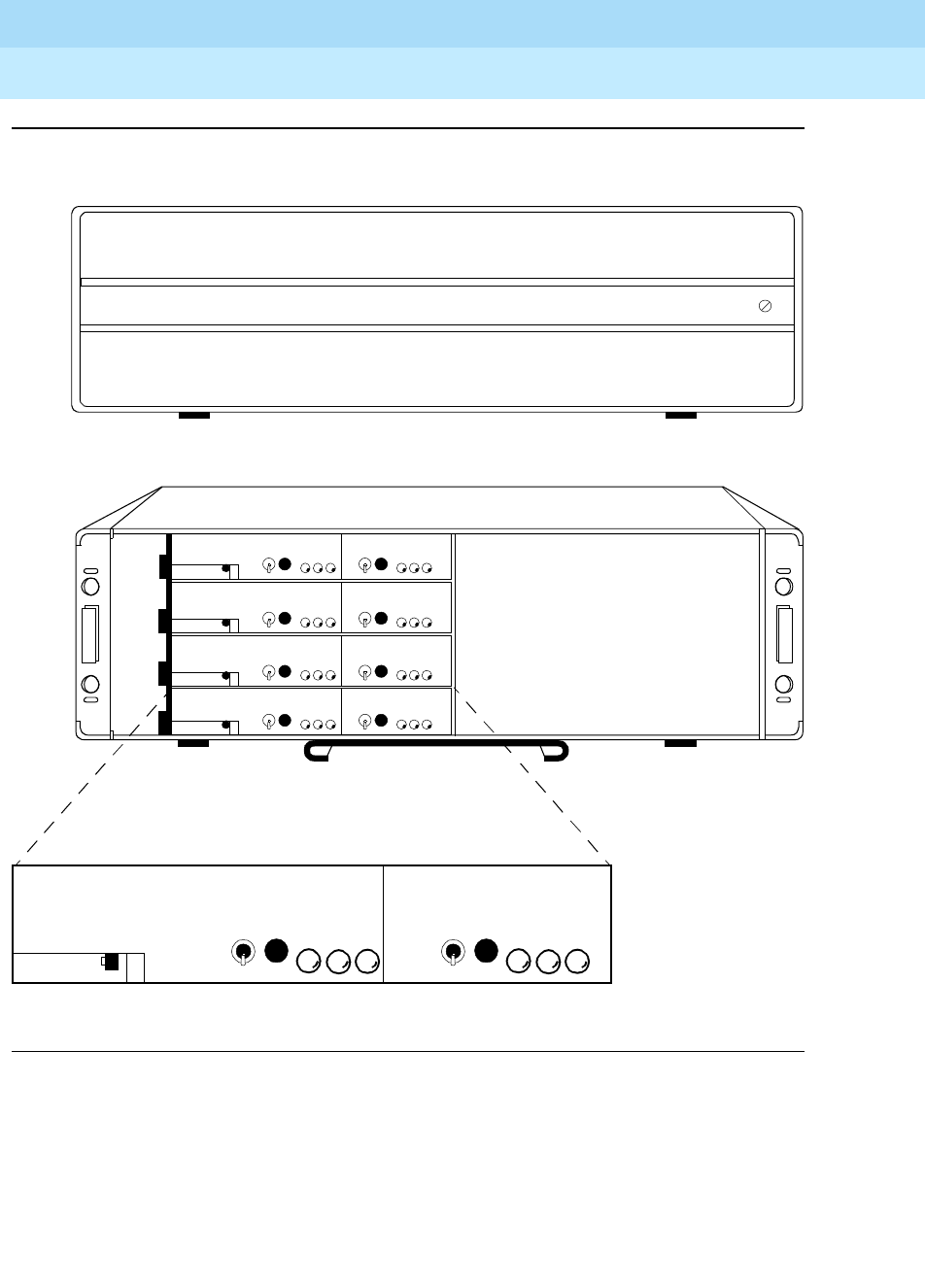
DEFINITYEnterpriseCommunicationsServerandSystem75andSystem85
Terminals and Adjuncts Reference
555-015-201 Issue 11
December 1999
Data Modules
21-78The 3270 Data Module
21
Figure 21-24. The 3270C Data Module
3270C Data Module
PORT A
4
3
2
1
B
U
S
Y
R
S
E
T
F
A
U
L
T
L
I
N
E
C
O
A
X
PORT B
B
U
S
Y
R
S
E
T
F
A
U
L
T
L
I
N
E
C
O
A
X

DEFINITYEnterpriseCommunicationsServerandSystem75andSystem85
Terminals and Adjuncts Reference
555-015-201 Issue 11
December 1999
Data Modules
21-79The 3270 Data Module
21
The 3270A and 3270T
Dimensions
NOTE:
The following dimensions are approximate.
Width = 5-3/4 inches
Depth (front to back) = 9-1/4 inches
Height = 1-1/2 inches
Lights
The following is a list of the lights on the 3270A and 3270T.
■Ter m in a l
■Computer
■Fault
Switches
The 3270A and 3270T have the following switches:
■Orig/Disc — located on the front
■Reset — located on the rear
Connectors
The 3270A and 3270T have the following connectors:
■Power
■Ter m in a l
■Aux Phone
■Wall Jack
Mounting Options
The 3270A and 3270T are desk mounted near the terminal with which it is used.

DEFINITYEnterpriseCommunicationsServerandSystem75andSystem85
Terminals and Adjuncts Reference
555-015-201 Issue 11
December 1999
Data Modules
21-80The 3270 Data Module
21
Cords
A D8W-87 cord is provided with the data module. The coaxial cable with BNC
male connectors for use between the data module and the terminal is customer
provided. If an analog telephone is to be connected, the required modular cord
must be provided with the telephone.
Power
An external power supply and the required cord is provided with the data module.
The power supply requires a 115-volt AC wall receptacle not under the control of a
wall switch.
The 3270C
Dimensions
NOTE:
The following dimensions are approximate.
Width = 19 inches
Depth (front to back) = 16-1/2 inches
Height = 5-3/4 inches
Lights
There are two sets of the following lights on the front panel of the data module:
■Coax
■Line
■Fault
Switches
There are two sets of the following lights on the front panel of the data module:
■Busy
■Reset

DEFINITYEnterpriseCommunicationsServerandSystem75andSystem85
Terminals and Adjuncts Reference
555-015-201 Issue 11
December 1999
Data Modules
21-81The 3270 Data Module
21
Connectors
The 3270 has the following connectors:
■Power
■DCP
■Port — The port connectors are labeled 1A, 2A, 3A, 4A, 1A, 1B,
1C, and 1D.
Mounting Options
The data module assembly may be stacked, wall mounted, or rack mounted near
the cluster controller to which it is connected.
Cords
A 7-1/2 foot AC power cord is provided with the unit. A 25-pair cable for the
connection to the DCP connector must be ordered separately. The coaxial cable
with BNC connectors for connection to the cluster controller must be provided by
the customer.
Power
All of the mounting arrangements require power from a 115-volt AC receptacle to
power the data module.
3270 Equipment PECs
The 3270 Data Modules can be ordered using the following PECs:
■3270A Data Module — 2168-A10 (not orderable)
■3270T Data Module — 2167-T10 (not orderable)
■3270C Data Module — 2166-C10
■3270C Data Module Circuit Card — 21660
Additional Documents
The following documents contain additional information relating to the 3270 data
module:
■
3270 Data Module User Manual
, 555-030-701
■
DEFINITY Generic 1 and Generic 2, System 75, and System 85 Terminals
and Adjuncts Installation and Test
, 555-015-104
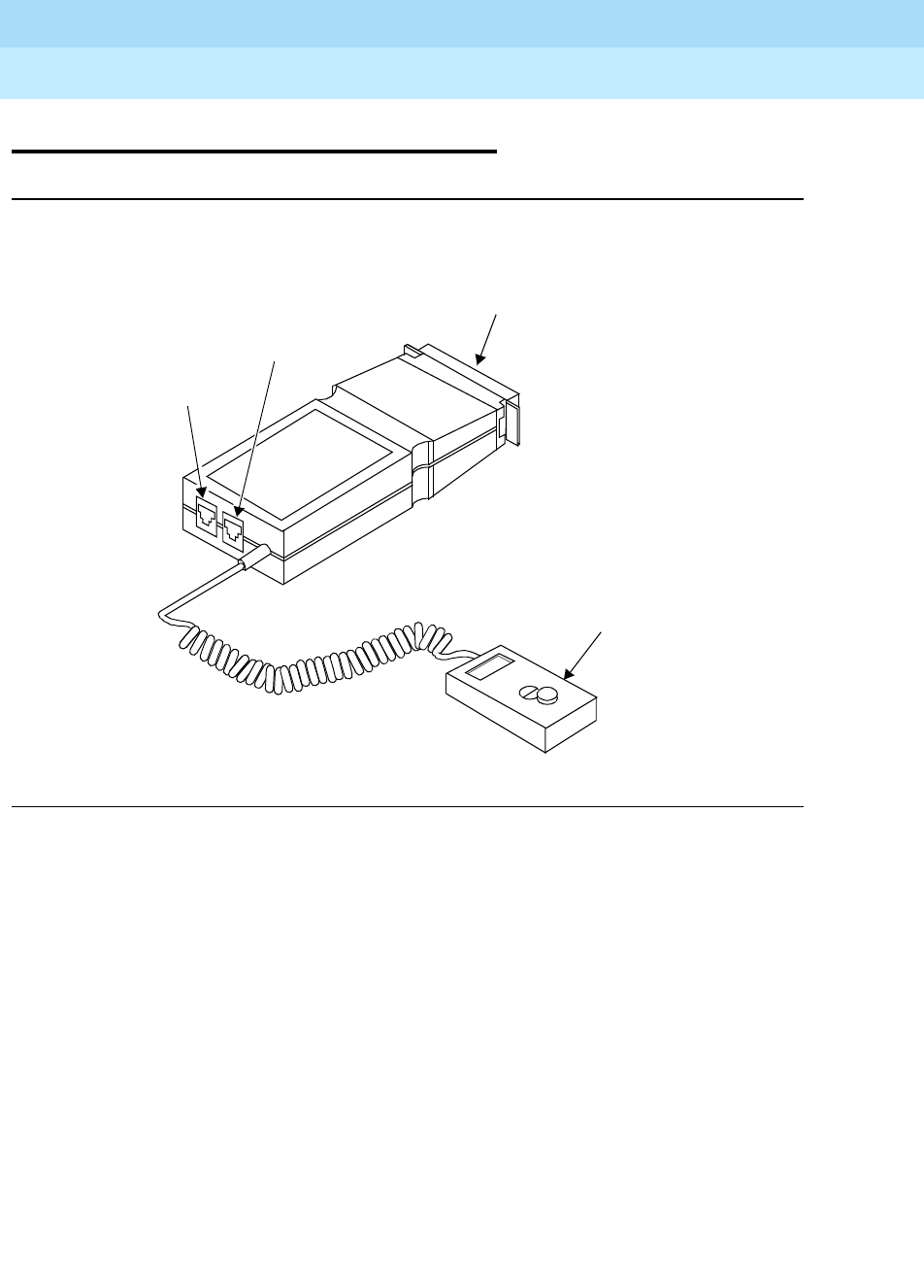
DEFINITYEnterpriseCommunicationsServerandSystem75andSystem85
Terminals and Adjuncts Reference
555-015-201 Issue 11
December 1999
Data Modules
21-82The Asynchronous Data Unit (ADU)
21
The Asynchronous Data Unit (ADU)
Figure 21-25. The Z3A Asynchronous Data Unit
The Z3A ADU is a small DCE-type limited-distance modem that allows direct
connection between RS-232 equipment and the system digital switch.The Z3A
ADU is a small DCE-type limited-distance modem that allows direct connection
between RS-232 equipment and the system digital switch. Used in conjunction
with the Data Line circuit pack (System 75 or a DEFINITY Communications
System Generic 1 and Generic 2) or the EIA Port circuit pack (System 85), the
ADU completes the direct link between the system switch and EIA terminals,
printers, and host computer ports. In these applications, DTE devices can access
the switch without using a separate data module or modem. The ADU is installed
at the device end of the EIA connection. ADUs can also be hard-wired in pairs
with other ADUs to interface data terminals directly to a host computer. This
application is typical when access to the host is not made through the system.
RS-232C Connector
Telephone Jack
Wall Jack
Optional
Originate/
Disconnect
Switch
Interface

DEFINITYEnterpriseCommunicationsServerandSystem75andSystem85
Terminals and Adjuncts Reference
555-015-201 Issue 11
December 1999
Data Modules
21-83The Asynchronous Data Unit (ADU)
21
Physical Description
Dimensions
NOTE:
The following dimensions are approximate.
Width = 2-1/4 inches
Depth = 4-3/4 inches
Height = 1 inch
Features
Switch
An optional Originate/Disconnect switch can be used with the Z3A1, Z3A2, and
Z3A4 ADUs.
Other Physical Features
Jacks
The ADU has the following jacks:
■Originate/Disconnect
The Z3A1/2/4 are equipped with a jack used to connect the optional
Originate/Disconnect switch.
■Telephone
The Z3A1/2/4 are equipped with modular jack to connect the optional
analog telephone.
■Data and RS-232 connections

DEFINITYEnterpriseCommunicationsServerandSystem75andSystem85
Terminals and Adjuncts Reference
555-015-201 Issue 11
December 1999
Data Modules
21-84The Asynchronous Data Unit (ADU)
21
Refer to the following table for the different data and RS-232 connections.
Capabilities
The ADU has the following data capabilities.
■Speed — Standard data rates from 0.3 to 19.2 kbps and non standard data
rates below 1.8 kbps. The auto adjust option will automatically match the
transmission speed to the attached RS-232.
■Full-duplex
■Asynchronous
■Built-in protection against voltage surges
Power
Under certain conditions the ADU is powered by the attached RS-232 equipment.
When the power provided by the RS-232 is inadequate (+7 volts are required on
pins 20 and 2), an external power transformer, adapter, and patch cord are
required.
Table 21-4. Data Connections for the ADU
ADU Model Connector to RS-232 Data Connector
Z3A1 25-pin plug on 3-foot cable Modular
Z3A2 25-pin plug (no cable) Modular
Z3A3 110-type patch cord 110-type patch cord
Z3A4 25-pin receptacle on 3-foot cable Modular

DEFINITYEnterpriseCommunicationsServerandSystem75andSystem85
Terminals and Adjuncts Reference
555-015-201 Issue 11
December 1999
Data Modules
21-85The Asynchronous Data Unit (ADU)
21
Z3A Data Module PECs
The Z3A Data Module and optional components can be ordered with the following
PECs:
■Z3A1 Asynchronous Data Module — 2169-001
■Z3A2 Asynchronous Data Module — 2169-002
■Z3A3 Asynchronous Data Module — 2169-003
■Z3A4 Asynchronous Data Module — 2169-004
■Originate/Disconnect Switch — 21692
■ADM Mounting Trough — 21693
Additional Documents
The following document contains information relating to the Z3A Data Module:
■
Asynchronous Data Unit Z3A User’s Manual
, 555-401-701
DEFINITYEnterpriseCommunicationsServerandSystem75andSystem85
Terminals and Adjuncts Reference
555-015-201 Issue 11
December 1999
Data Modules
21-86The Multiple Asynchronous Data Unit (MADU)
21
The Multiple Asynchronous Data Unit
(MADU)
The MADU provides an RS-232-C compatible, full-duplex, asynchronous data
interface which provides host computer access for a variety of DTE devices. The
MADU converts information sent to it from a host computer in RS-232-C protocol
to low-voltage signals. These signals can be transmitted over standard building
wiring or to the switch over much greater distances than regular EIA signals may
travel. The host computer is set up to appear as a DCE device to the MADU. The
MADU sends the converted information out through its building wiring interface.
Capabilities
The MADU has the following data capabilities.
■Speed — Standard data rates from 0.3 to 19.2 kbps and nonstandard data
rates below 1.8 kbps. The auto adjust option will automatically match the
transmission speed to the attached RS-232-C device.
■Full-duplex
■Asynchronous
■Built in protection against voltage surges
Physical Description
Dimensions — stand-alone housing
NOTE:
The following dimensions are approximate.
Width = 8-3/4 inches
Depth = 12 inches
Height = 2-3/4 inches
Dimensions — multiple mount carrier
NOTE:
The following dimensions are approximate.
Width = 17-1/2 inches
Depth = 18 inches
Height = 8-3/4 inches

DEFINITYEnterpriseCommunicationsServerandSystem75andSystem85
Terminals and Adjuncts Reference
555-015-201 Issue 11
December 1999
Data Modules
21-87The Multiple Asynchronous Data Unit (MADU)
21
Dimensions — MADU circuit pack
NOTE:
The following dimensions are approximate.
Width = 1-3/4 inches
Length = 11-1/4 inches
Height = 7-3/4 inches
Features
Switch
Each port on each circuit pack has a MK BUSY switch on the faceplate.
Each MADU circuit pack contains a 10-position Dual In-line Package (DIP) switch
to activate or disable options.
Lights
■Red
■DTR
■Busy
Connectors
■To Building Wiring
■Power
■To Host computer
Other Physical Features
Cords
A 2-pair modular power cord, two centerfeed to endfeed cables (specify male or
female when ordering), and an octopus cable (specify M48C for DTE or M48G for
DCE equipment) is provided with the MADU. Any other cables or adapters must
be ordered separately or be provided by the customer.
Mounting — Stand-alone
A single MADU circuit pack may be installed in a stand-alone mounting providing
eight ports. The stand-alone housings can be desk mounted. If more than one
stand-alone housing is provided, they may be stacked.

DEFINITYEnterpriseCommunicationsServerandSystem75andSystem85
Terminals and Adjuncts Reference
555-015-201 Issue 11
December 1999
Data Modules
21-88The Multiple Asynchronous Data Unit (MADU)
21
Mounting — Multiple mount
The multiple-mount MADU may be rack or cabinet mounted. The MADU may be
mounted in 19, 23, or 25 inch racks. If the MADU is to be mounted in a cabinet,
the cabinet must be 23 or 25 inches wide to provide clearance for the cabling.
Power
Each MADU circuit pack is powered from an individual transformer which is
plugged into an AC power source. The transformer may be plugged directly into a
wall outlet for four or fewer units. For more than four MADU packs, transformers
should be plugged into a multiple-mount carrier’s power distribution box or
commercially available power strip with an RF filter.
MADU Circuit Pack PECs
The MADU can be ordered using the following PECs:
■MADU single unit assembly — 2169-005
■MADU carrier assembly — 2169-006
■MADU circuit pack — 21694
■MADU power transformer — 21695
Additional Documents
The following document contains additional information on the MADU:
■
Multiple Asynchronous Data Unit (MADU) User’s Manual
, 555-401-702

DEFINITYEnterpriseCommunicationsServerandSystem75andSystem85
Terminals and Adjuncts Reference
555-015-201 Issue 11
December 1999
Data Modules
21-89DCIU Interface Units
21
DCIU Interface Units
The three interface units used in a DEFINITY Communications System Generic 2
and System 85 DCIU link are the 105A Isolating Data Interface (IDI), the 48250
Local Distribution Service Unit (LDSU), and the 2500-Series Data Service Unit
(DSU).
105A IDI
The IDI is a miniature connection unit for point to point, synchronous, full-duplex
operation between the DCIU and an external processor. The DCIU and the
external processor can be a maximum of 400 feet apart. Only one IDI is required
in each DCIU link.
Some of the features of the IDI are:
■No options or adjustments
■0.3 through 19.2 kbps
■Uses DCIU timing
■Powered from the EIA control signals
48250 LDSU
The LDSU interfaces the System 85 DCIU with an external processor. It provides
the required isolation between the DCIU and the external processor. Two LDSUs
per external processors are required.
Each LDSU contains:
■A transmitter with filtering and modulation — allows data transmission at
speeds from 2.4 kbps up to 19.2 kbps
■A receiver with equalization, demodulation, clock recovery, and signal
presence detection — accepts incoming data from a 150 ohm line
■A regulated DC power supply for the required DC voltage
■An EIA RS-232-C interface
NOTE:
Each LDSU requires a 120-volt AC source.
2500-Series DSU
The 2500-Series DSU can be used as a Local Area Data Set for distances over
400 feet. Refer to the 2500-Series DSU section later in this chapter of the manual
for the information on the DSU.

DEFINITYEnterpriseCommunicationsServerandSystem75andSystem85
Terminals and Adjuncts Reference
555-015-201 Issue 11
December 1999
Data Modules
21-90The 2500-Series DSU
21
The 2500-Series DSU
The 2500-Series DSUs allow the user’s computer or DTE to communicate with
remotely located equipment using Digital Data Service network lines. The DSU
integrates all Channel Service Unit (CSU) and DSU functions into one unit and
connects between the network interface and the user’s DTE.
The DSU can operate as a point-to-point Local Area Data Set (LADS). It is used
when the DCIU and external processor are more than 400 feet apart. Two DSUs
per external processor are required.
Physical Description
The following lists describe the dimensions of the DSUs.
■Stand-alone Dimensions (approximate)
Width = 5-3/4 inches
Depth (front to back) = 9-5/8 inches
Height = 2 inches
■Multiple Mounting Dimensions (approximate)
Width = 23 inches
Depth (front to back) = 20 inches
Height = 7 inches
Capabilities
The following are the data capabilities of the DSUs.
■Full-duplex
■Synchronous operation
■Asynchronous operations with certain limitations when used as a LAD
■Three color test and status LCD panel
■Multi test functions
■Two color test and Status/Fault indicator
■User selectable options
Operating Speeds
The 2556A, 2556B, and 2556C operate at 56 kbps. The 2596A, 2596B, and
2596C have selectable subrates of 2.4, 4.8, or 9.6 kbps. When used as a LAD,
they can also be optioned for 19.2 and 64 kbps operation.

DEFINITYEnterpriseCommunicationsServerandSystem75andSystem85
Terminals and Adjuncts Reference
555-015-201 Issue 11
December 1999
Data Modules
21-91The 2500-Series DSU
21
Mounting
The 2500-Series DSU can be stand-alone or multiple mounted. The stand-alone
units can be wall or desk mounted. The multiple mounted units are mounted in a
multiple-mount housing that can house up to eight DSUs.
Power
The stand-alone units are provided with a WP90131-L2 power pack. This power
pack is plugged into a 115-volt AC wall receptacle not under the control of a wall
switch. The multiple-mount housing is provided with a 6-foot power cord that is
plugged into a 115-volt AC wall receptacle not under control of a wall switch. Each
DSU that is to mounted into the multiple-mount housing is equipped with a
WP90131-L1 power pack that is plugged into the power strip on the rear of the
housing.
Distance Limitations
The 2556A, 2556B, and 2556C DSUs may be located a maximum distance of 50
feet from the DTE. The 2596A, 2596B, and 2596C DSUs may be located a
maximum distance of 100 feet from the DTE.
2500-Series DSU PECs
The 2500-Series DSUs and optional components can be ordered using the
following PECs:
■2556A Data Service Unit — 2225-56A
■2596A Data Service Unit — 2225-96A
■2556B Data Service Unit — 2225-56B
■2596B Data Service Unit — 2225-96B
■2556C Data Service Unit — 2225-56C
■2596C Data Service Unit — 2225-96C
■2500-Series Multiple-Mounting Housing — 22253
■2600-Series Multiple-Mounting Housing — 22263
Additional Documents
The following document contains additional information relating to the
2500-Series Data Service Unit:
■
2500-Series Data Service Unit User’s Manual
, 999-100-188

DEFINITYEnterpriseCommunicationsServerandSystem75andSystem85
Terminals and Adjuncts Reference
555-015-201 Issue 11
December 1999
Data Modules
21-92The 2500-Series DSU
21

PC Platforms (PC/PBX and PC/ISDN) and Application Software
22-1
22
DEFINITYEnterpriseCommunicationsServerandSystem75andSystem85
Terminals and Adjuncts Reference
555-015-201 Issue 11
December 1999
22
PC Platforms (PC/PBX and PC/ISDN)
and Application Software
This section describes the devices that provide the ability to bring the PC and
telephone together in a partnership of integrated voice and data. The platforms
and software covered in this section are:
■PC/PBX Platform
■PC/PBX MicroChannel Architecture Platform
■PC/ISDN Platform
■PC/PBX Connection
■E78 Plus/ISDN Software

DEFINITYEnterpriseCommunicationsServerandSystem75andSystem85
Terminals and Adjuncts Reference
555-015-201 Issue 11
December 1999
PC Platforms (PC/PBX and PC/ISDN) and Application Software
22-2PC Platforms (PC/PBX and PC/ISDN)
22
PC Platforms (PC/PBX and PC/ISDN)
Today, professional PC users seek to realize the promise of desktop computing
productivity by accessing multiple data sources — local and remote, internal and
external. Lucent Technologies PC Platforms provide both a high speed connection
to the PC and an open software interface for creating applications that use the
connection.
Overview
The PC platforms are “open platforms” that allow software developers to build
applications that take advantage of ISDN capabilities. The three platforms
(PC/PBX, PC/PBX MicroChannel Architecture, and PC/ISDN) support a common
data Applications Programming Interface (API) that provides applications
portability between the DCP protocol and the ISDN-BRI. The common API
protects the DEFINITY switch customers who have invested in DCP while
providing a large installed DCP base for third party applications as well as the
growing BRI market.
Platforms
The PC/PBX and PC/PBX MicroChannel Architecture platforms can be used with
the DEFINITY Communications System Generic 1, Generic 2, and Generic 3, the
DEFINITY ECS, System 75, and System 85. The PC/ISDN platform can be used
with DEFINITY G2 and G3, the DEFINITY ECS, and the 5ESS (Generic 5E4.2
and 5E5) switch. The platforms are particularly useful for building applications for
those users who wish to use their PCs as a terminal for a host computer or wish to
have their PC communicate with other PCs.
The connection between the PC and PBX can be either:
■DCP interface — the protocol for System 75, System 85, the DEFINITY
G1, G2, and G3, and the DEFINITY ECS
■ISDN Basic Rate Interface (BRI) — available with DEFINITY G2 and G3,
the DEFINITY ECS, and 5ESS switch
Physically, an expansion card is inserted in the PC and connected to the PBX via
unshielded twisted pair wiring. A separate card is needed for DCP and BRI. Since
these cards feature a voice port, they also support integrated voice-data
applications as well as data networking.

DEFINITYEnterpriseCommunicationsServerandSystem75andSystem85
Terminals and Adjuncts Reference
555-015-201 Issue 11
December 1999
PC Platforms (PC/PBX and PC/ISDN) and Application Software
22-3PC Platforms (PC/PBX and PC/ISDN)
22
PC/PBX and PC/PBX MicroChannel Platforms
The PC/PBX platforms provide standalone PC users with a fully integrated
networking solution that brings the benefits of high-speed, error free digital
communications to the desktop. The PC/PBX platform supports existing
configurations in which both the voice terminal and the PC are connected to the
PBX via a single DCP line.
The PC/PBX MicroChannel Architecture platform is the same as the PC/PBX
platform, but is intended for use with the IBM PS/2 Model 50 and above.
Applications
The platforms are ideal for professionals and managers who perform many
different tasks during the day. The platform architecture permits different PC
applications to access its resources alternatively or simultaneously. The PC/PBX
Platforms support the 7400 Series voice terminals.
Potentially, a user could hold a voice conversation, be asynchronously connected
to a host or PC, or conduct a 64 kbps 3270 session to a mainframe over a single
twisted-pair connection. This eliminates the need for such multiple PC
communications adapters as modems and coax cards.
Capabilities
Used in conjunction with PC applications software, the PC/PBX Platform provides
the hardware architecture at the desktop for:
■High-speed PC-to-PC communication
■Access to asynchronous host environments
■Access to the synchronous 3270 environment
■Advanced telephone management capabilities
The PC/PBX Platform can also run the PC/PBX Connection software for
integrating voice and data applications at the desktop. Thus, the platform supports
all of the following:
■Synchronous communication via 3270 emulation with file transfer
capabilities
■Asynchronous communication via VT®100, VT102, and 4410 terminal
emulation at speeds up to 19.2 kbps
■Digital Multiplexed Interface (DMI) connectivity at 64 kbps
■High-speed PC-to-PC communication for error-free file transfers at speeds
up to 64 kbps via such standard asynchronous file transfer protocols as
XMODEM and KERMIT

DEFINITYEnterpriseCommunicationsServerandSystem75andSystem85
Terminals and Adjuncts Reference
555-015-201 Issue 11
December 1999
PC Platforms (PC/PBX and PC/ISDN) and Application Software
22-4PC Platforms (PC/PBX and PC/ISDN)
22
■Advanced phone management capabilities including:
— Incoming call identification
— Personal directory with up to 32,000 entries
— Keyboard dialing
— Messaging
— Call log and notes
— Switch feature access
— Multiple call appearances
PC/PBX PECs
The PC/PBX platform package can be ordered using PEC 8302-101. The
PC/PBX MicroChannel Architecture platform package can be ordered using
PEC 8302-105.
These packages contain:
■AninterfacecardforthePC
■System software — a device driver and hardware/software diagnostic
utilities
■Installation and Reference guide
PC/ISDN Platform
The PC/ISDN platform provides standalone PC users with a fully integrated
network solution in an ISDN environment. Supporting the full “2B+D” BRI, the
platform brings to the desktop the benefits of high-speed, error-free digital
communications.
Applications
The platform is ideal for professionals and managers who perform many different
tasks during the day. The platform architecture permits different PC applications
to access its resources alternatively or simultaneously. The PC/ISDN Platform
supports the ISDN-BRI 7500 Series voice terminals.
Potentially, a user could hold a voice conversation, be asynchronously connected
to a host or PC, or conduct a 64 kbps 3270 session to a mainframe over a single
twisted-pair connection. This eliminates the need for such multiple PC
communications adapters as modems and coax cards.

DEFINITYEnterpriseCommunicationsServerandSystem75andSystem85
Terminals and Adjuncts Reference
555-015-201 Issue 11
December 1999
PC Platforms (PC/PBX and PC/ISDN) and Application Software
22-5PC Platforms (PC/PBX and PC/ISDN)
22
Capabilities
Used in conjunction with PC applications software, the PC/PBX Platform provides
the hardware architecture at the desktop for:
■High-speed PC-to-PC communication
■Access to asynchronous host environments
■Access to the synchronous 3270 environment
■Advanced telephone management capabilities
In addition, the PC/ISDN Platform supports the capabilities of the ISDN-BRI 7500
Series voice terminals including:
■Conference, Transfer, Hold, and Drop
■Up to 254 call appearances
■Display and light indicator control supported from the application
■On-board digital signal processing for Dual Tone Multi-Frequency (DTMF
or Touch-Tone) generation
PC/ISDN PECs
The PC/ISDN platform package can be ordered using PEC 8302-104. This
package contains:
■AninterfacecardforthePC
■System software — a device driver, downloadable firmware, and utilities
■Installation and Reference Guide
Additional Documents
The following documents contain additional information relating to the PC
platforms.
■
PC/ISDN Interface Software Developers Guide
, 555-016-103
■
PC/PBX Platform Installation and Reference
, 555-016-101
■
PC/ISDN Platform Installation and Reference
, 555-016-102

DEFINITYEnterpriseCommunicationsServerandSystem75andSystem85
Terminals and Adjuncts Reference
555-015-201 Issue 11
December 1999
PC Platforms (PC/PBX and PC/ISDN) and Application Software
22-6PC/PBX Connection
22
PC/PBX Connection
The PC/PBX Connection application software offers the users of IBM compatible
PCs the voice and data capabilities of a fully integrated voice and data
workstation.
Applications
The PC/PBX Connection application software can be used with the DEFINITY
Communications System Generic 1, Generic 2, and Generic 3, the DEFINITY
ECS, System 75, and System 85. It is particularly useful for those users who wish
to use their PCs as a terminal for a host computer or wish to have their PC
communicate with other PCs. It is targeted to “power” telephone users who want
to eliminate many pieces of equipment from their desk.
Capabilities
The PC/PBX Connection can be used to perform the following activities:
■Dial calls from a PC keyboard
■Use customized telephone features from a keyboard
■Set up a personal telephone directory, search the directory, and dial voice
and data calls from the directory (it can contain up to 32,000 entries)
■Know when telephone messages were received, read the messages on the
screen, and have the system automatically dial calls to people who have
left messages
■Log all incoming and outgoing voice and data calls and recall them on
the PC
■Use voice terminal and speakerphone or voice terminal with built-in
speakerphone to make hands-free calls
■Use security feature to keep directory and message information private
■Use a PC as a terminal connected to a variety of host computers
(synchronous and asynchronous)
■Transfer files between a PC and another PC or host computer
■Set up “script programs” to have the system perform certain data functions
Moreover, voice and data functions can be used simultaneously, and other PC
applications can be run while running PC/PBX connection in the background.

DEFINITYEnterpriseCommunicationsServerandSystem75andSystem85
Terminals and Adjuncts Reference
555-015-201 Issue 11
December 1999
PC Platforms (PC/PBX and PC/ISDN) and Application Software
22-7PC/PBX Connection
22
PC/PBX PECs
The PC/PBX Connection can be ordered using the following PECs:
■PC/PBX Connection Software — 1211-101
■PC/PBX Connection Hardware (PC/PBX Platform) — 8302-101
■PC/PBX Connection Hardware (PC/PBX MicroChannel
Platform) — 8302-105
Additional Documents
The following documents contain additional information relating to the PC/PBX
Connection:
■
PC/PBX Connection Release 3 Documentation Set
, 555-016-715
■
PC/PBX Connection Installation and Reference
, 555-016-201
■
PC/PBX Platform Installation and Reference
, 555-016-101

DEFINITYEnterpriseCommunicationsServerandSystem75andSystem85
Terminals and Adjuncts Reference
555-015-201 Issue 11
December 1999
PC Platforms (PC/PBX and PC/ISDN) and Application Software
22-8E78 Plus/ISDSN Software
22
E78 Plus/ISDSN Software
The E78 Plus/ISDN is a 3270 terminal emulation and file transfer package for
micro-mainframe connectivity. However, its use in remote applications was, until
recently, limited because of low-speed connections between locations. Now, used
with any of the Lucent Technologies PC Platforms, E78 Plus/ISDN provides full
3270 emulation with switched connections through the DEFINITY switch using
either DCP or ISDN-BRI at speeds of 64 kbps.
Applications
The E78 Plus/ISDN software can be used with the DEFINITY Communications
System Generic 1, Generic 2, and Generic 3, the DEFINITY ECS, System 75,
System 85, and 5ESS switch. It is particularly useful for those PC users who wish
to download large amounts of data stored on central site mainframes to their
desktop environment for processing and/or storage. The high-speed connection
permits a PC user to transfer a large file quickly from a remote mainframe.
Therefore, it is possible for users to download large quantities of data for desktop
processing and analysis on a daily basis.
Physical Description
The E78 Plus/ISDN provides a variety of transfer programs (for example,
IRMAlink FT/TSO, FT/CMS, and FT/3270) to quickly and safely transfer text and
binary files. These programs offer both menu and command-line operation in all
major mainframe environments.
On the host side, a Lucent Technologies 3270C Data Module must reside
between the cluster controller and switch. The PC must be equipped with either
PC/ISDN Platform (BRI) Release 1.0 or later
or
PC/PBX Platform (DCP)
Release3.01orlatersoftware.
Capabilities
The E78 Plus/ISDN software can be used to perform the following activities:
■High-speed (64 kbps) connectivity
■Eliminate the need for costly remote controllers
■Allow terminals to access applications on hosts that are not networks,
thereby reducing the number of terminals required
■Transfer a large file quickly from a remote mainframe
■Integrate with PC/PBX Connection to provide simultaneous voice and data
connectivity
In addition, E78 Plus/ISDN provides productivity extras professionals expect,
such as:

DEFINITYEnterpriseCommunicationsServerandSystem75andSystem85
Terminals and Adjuncts Reference
555-015-201 Issue 11
December 1999
PC Platforms (PC/PBX and PC/ISDN) and Application Software
22-9E78 Plus/ISDSN Software
22
■Keyboard Macros. Frequently repeated commands and complex data
strings can be stored on the keyboard. The same key can store different
macros for DOS and 3270 emulation.
■Keyboard Remap. This utility lets the user easily modify keyboard layouts
and create new ones for new applications.
■Hot Keys. Convenient hot keys allow the user to do things quickly — switch
between PC and emulation sessions, jump to a file transfer menu, access
DOS, or get help.
■Save and Print Screens. The user can capture screens, as needed: in a
disk file, PC internal memory or at a printer.
E78 PECs
The E78 Plus/ISDN software can be ordered using PEC 1211-102.
Additional Documents
Documentation for this software is provided with the purchased product.

DEFINITYEnterpriseCommunicationsServerandSystem75andSystem85
Terminals and Adjuncts Reference
555-015-201 Issue 11
December 1999
PC Platforms (PC/PBX and PC/ISDN) and Application Software
22-10E78 Plus/ISDSN Software
22

Blank Templates for Model Design
23-1
23
DEFINITY® Enterprise Communications Server and System 75 and System
85 Terminals and Adjuncts Reference
555-015-201 Issue 10
December 1998
23
Blank Templates for Model Design
The Software Associate can use the following blank templates to create models
for administering groups of terminals at a customer site. Use the following
procedures for filling out these forms.
1. In each button space write the telephone number, extension, feature code,
or feature to be administered on that button. Note that some of the voice
terminals have double-level buttons on which you can designate two
features.
2. If the model design is to be used on other voice terminals, write the Model
Name at the top of the form beside Model Name.
3. Fill in your name by Software Associate.
4. Write the numbers and letters of the project code beside Project Code.
5. When the customer has approved the button assignments designated on
the templates, have the customer sign the form beside Customer
Approval.
6. Beside Date, write the date that the customer signed the form.
The following voice terminal templates are available for your use:
■6408+
■6408D+
■6416D+
■6424D+
■7402 Plus
■7406D

DEFINITY® Enterprise Communications Server and System 75 and System
85 Terminals and Adjuncts Reference
555-015-201 Issue 10
December 1998
Blank Templates for Model Design
23-2
23
■7406BIS
■7406 Plus
■7407D
■Enhanced 7407D
■7407 Plus
■7410D
■7410 Plus
■7434D
■7444
■8403
■8405B and 8405B Plus
■8405D and 8405D Plus
■8410B
■8410D
■8411B
■8411D
■8434 and 8434DX
■801A Expansion Module
■602 CALLMASTER
■CALLMASTER II and III (603)
■CALLMASTER IV
■CALLMASTER VI
■ISDN 7505
■ISDN 7506
■ISDN 7507
■ISDN 8503T
■ISDN 8510T
■ISDN 8520T
7
PQRS
3
DEF
Speaker Mute Hold
Redial Transfer Conf
Test Ring
2
ABC
1
4
GHI
56
89
MNOJKL
TUV WXYZ
O
#
Volume
Tel #
MODEL NAME: __________________________
The 6408+ Telephone
Software Associate: ______________
Project Code: ___________________
Customer Approval: ______________________
Date: __________________________________
7
PQRS
3
DEF
Speaker Mute Hold
Redial Transfer Conf
Test Ring
2
ABC
1
4
GHI
56
89
MNOJKL
TUV WXYZ
O
#
Volume
Menu Exit Prev Next
Tel #
MODEL NAME: __________________________
The 6408D+ Telephone
Software Associate: ______________
Project Code: ___________________
Customer Approval: ______________________
Date: __________________________________
7
PQRS
3
DEF
Speaker Mute Hold
Redial Transfer Conf
Test Ring
2
ABC
1
4
GHI
56
89
MNOJKL
TUV WXYZ
O
#
Volume
Menu Exit Prev Next
Tel #
MODEL NAME: __________________________
The 6416D+ Telephone
Software Associate: ______________
Project Code: ___________________
Customer Approval: ______________________
Date: __________________________________
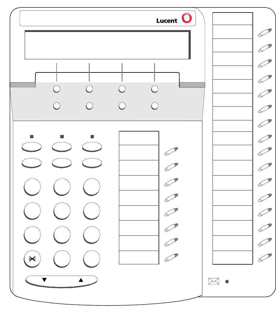
7
PQRS
3
DEF
Speaker Mute Hold
Redial Transfer Conf
Test Ring
2
ABC
1
4
GHI
56
89
MNOJKL
TUV WXYZ
O
#
Volume
Menu Exit Prev Next
Tel #
MODEL NAME: __________________________
The 6424D+ Telephone
Software Associate: ______________
Project Code: ___________________
Customer Approval: ______________________
Date: __________________________________
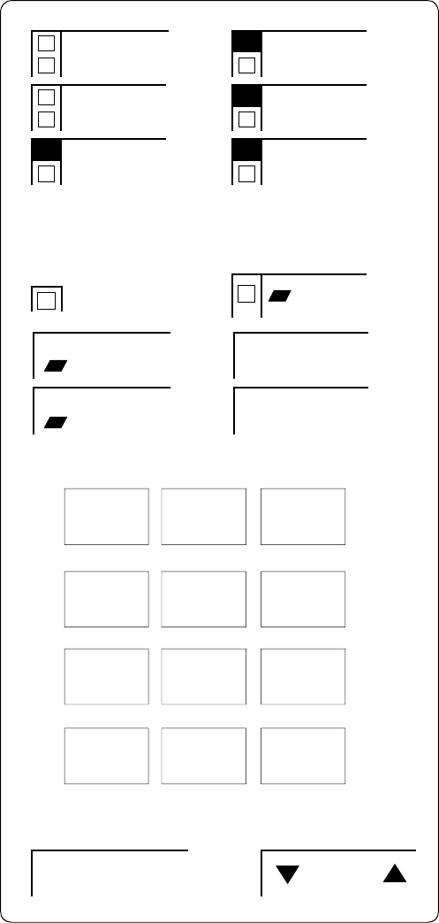
Conference
Drop
Transfer
Hold
Speaker Volume
Ring
Test
Message Select
123
456
789
ABC DEF
MNOJKLGHI
PQRS TUV WXYZ
*
O#
Oper
MODEL NAME: ____________________
The 7402 Plus Voice Terminal
Software Associate: ____________________
Project Code: _________________________ Date: ______________________________
Customer Approval: __________________
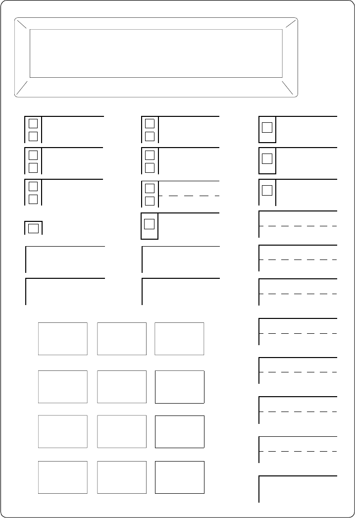
123
456
789
ABC DEF
MNOJKLGHI
PRS TUV WXY
*
O
#
Oper
Conference
Drop
Transfer
Hold
Message
Select Ring
Shift
Speaker
The 7406D Voice Terminal
MODEL NAME: ____________________
Software Associate: ____________________
Project Code: _________________________ Date: ______________________________
Customer Approval: __________________
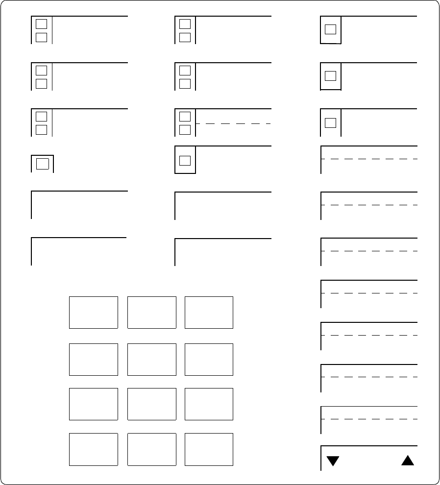
Conference
Drop
Transfer
Hold
Message
Select Ring
Shift
Speaker
The 7406BIS Voice Terminal
MODEL NAME: ____________________
Software Associate: ____________________
Project Code: _________________________ Date: ______________________________
Customer Approval: __________________
123
456
789
ABC DEF
MNOJKLGHI
PRS TUV WXY
*
O
#
Oper
Volume
Speaker
Mute
Conference
Drop
Transfer
Hold
Message Select
Speaker
Mute
Ring
Test
Reset Spkr
Volume
123
456
789
ABC DEF
MNOJKLGHI
PQRS TUV WXYZ
*
O
#
Oper
The 7406 Plus Voice Terminal
MODEL NAME: ____________________
Software Associate: ____________________
Project Code: _________________________ Date: ______________________________
Customer Approval: __________________
Conference
Drop
Transfer
Hold
Message Speakerphone
Calculator
Microphone
Display Select Ring
P
R
C/
CE
M
R
M
M
+
X
+
-
+
✓
-
=
The 7407D Voice Terminal
Software Associate: ____________________
Project Code: _________________________ Date: ______________________________
Customer Approval: __________________
MODEL NAME: ____________________
123
456
789
ABC DEF
MNOJKLGHI
PRS TUV WXY
*
O#
Oper
Conference
Drop
Transfer
Hold
Speaker
Select
Mute
Message Ring
The Enhanced 7407D Voice Terminal
Software Associate: ____________________
Project Code: _________________________ Date: ______________________________
Customer Approval: __________________
MODEL NAME: ____________________
123
456
789
ABC DEF
MNOJKLGHI
PRS TUV WXY
*
O#
Oper
Volume
Conference
Drop
Transfer
Hold
Speaker
Select
Mute
Message
The 7407 Plus Voice Terminal
Software Associate: ____________________
Project Code: _________________________ Date: ______________________________
Customer Approval: __________________
MODEL NAME: ____________________
123
456
789
ABC DEF
MNOJKL
GHI
PQRS TUV WXYZ
*
O#
Oper
Volume
Ring
Test
Reset/Spkr
Conference
Drop
Transfer
Hold
Message Select
123
456
789
ABC DEF
MNOJKLGHI
PRS TUV WXY
*
O#
Oper
MODEL NAME: ____________________
The 7410D Voice Terminal
Software Associate: ____________________
Project Code: _________________________ Date: ______________________________
Customer Approval: __________________
Ring
Conference
Drop
Transfer
Hold
Speaker Volume
Ring
Test
Message Select
123
456
789
ABC DEF
MNOJKLGHI
PQRS TUV WXYZ
*
O#
Oper
MODEL NAME: ____________________
The 7410 Plus Voice Terminal
Software Associate: ____________________
Project Code: _________________________ Date: ______________________________
Customer Approval: __________________
Conference
Drop
Transfer
Hold
Message Select
Ring
MODEL NAME: ____________________
The 7434D Voice Terminal
Software Associate: ____________________
Project Code: _________________________ Date: ______________________________
Customer Approval: __________________
123
456
789
ABC DEF
MNOJKLGHI
PRS TUV WXY
*
O#
Oper
Conference
Drop
Transfer
Hold
Speaker
Select
Mute
Message
The7444VoiceTerminal
Software Associate: ____________________
Project Code: _________________________ Date: ______________________________
Customer Approval: __________________
MODEL NAME: ____________________
123
456
789
ABC DEF
MNOJKLGHI
PQRS TUV WXYZ
*
O#
Oper
Volume
Ring
Test
Reset/Spkr

123
456
789
ABC DEF
MNOJKLGHI
PQRS TUV WXYZ
*
O#
MODEL NAME:_________________
The8403VoiceTerminal
Software Associate:_______________
Project Code:____________________
Customer Approval:_______________
Date:___________________________
8403
Transfer
Hold
ab c
Feature
Volume
Test Conf
Drop
Mute
Ring
Speaker
Message
F1
F2
F3
F4
F5
F6
F7
F8
F9
F*
F0
F#
Volume
Shift Transfer
Test Conf
Mute Drop
Speaker Hold
123
456
789
ABC DEF
MNOJKLGHI
PQRS TUV WXYZ
*
O#
MODEL NAME:_________________
The 8405B and 8405B Plus Voice Terminal
Software Associate:_______________
Project Code:____________________
Customer Approval:_______________
Date:___________________________
8405B
Volume
Shift Transfer
Test Conf
Mute Drop
Speaker Hold
123
456
789
ABC DEF
MNOJKLGHI
PQRS TUV WXYZ
*
O#
NextPrevMenu Exit
MODEL NAME:_________________
The 8405D and 8405D Plus Voice Terminal
Software Associate:_______________
Project Code:____________________
Customer Approval:_______________
Date:___________________________
Volume
Shift Transfer
Test Conf
Mute Drop
Speaker Hold
Reset Spkr
123
456
789
ABC DEF
MNOJKLGHI
PQRS TUV WXYZ
*
O#
8410B
Ring
MODEL NAME:_________________
The 8410B Voice Terminal
Software Associate:_______________
Project Code:____________________
Customer Approval:_______________
Date:___________________________
Message

Volume
Shift
Transfer
Test Conf
Mute Drop
Speaker
Hold
Reset Spkr
123
456
789
ABC DEF
MNOJKLGHI
PQRS TUV WXYZ
*
O#
8410D
Next
Prev
Menu Exit
Ring
MODEL NAME:_________________
The 8410D Voice Terminal
Software Associate:_______________
Project Code:____________________
Customer Approval:_______________
Date:___________________________
Message
Volume
Shift
Transfer
Test Conf
Mute Drop
Speaker
Hold
Reset Spkr
123
456
789
ABC DEF
MNOJKLGHI
PQRS TUV WXYZ
*
O#
8411B
Ring
MODEL NAME:_________________
The 8411B Voice Terminal
Software Associate:_______________
Project Code:____________________
Customer Approval:_______________
Date:___________________________
Message
Volume
Shift
Transfer
Test Conf
Mute Drop
Speaker
Hold
Reset Spkr
123
456
789
ABC DEF
MNOJKLGHI
PQRS TUV WXYZ
*
O#
8411D
Next
Prev
Menu Exit
Ring
MODEL NAME:_________________
The 8411D Voice Terminal
Software Associate:_______________
Project Code:____________________
Customer Approval:_______________
Date:___________________________
Message
MODEL NAME:_________________
The 8434 and 8434DX Voice Terminal
Software Associate:_______________
Project Code:____________________
Customer Approval:_______________
Date:___________________________
123
456
789
ABC DEF
MNOJKLGHI
PQRS TUV WXYZ
*
O#
Volume
Shift
Transfer
Test Conf
Mute Drop
Speaker
Hold
Reset Spkr
Ring
8434DX
NextPrevMenu Exit
Message
801A
MODEL NAME:_________________
The 801A Expansion Module
Software Associate:_______________
Project Code:____________________
Customer Approval:_______________
Date:___________________________
Conference
Drop
Transfer
Hold
Message
The 602 CALLMASTER Voice Terminal
Software Associate: ____________________
Project Code: _________________________ Date: ______________________________
Customer Approval: __________________
MODEL NAME: ____________________
123
456
789
ABC DEF
MNOJKLGHI
PRS TUV WXY
*
O#
Oper Mute
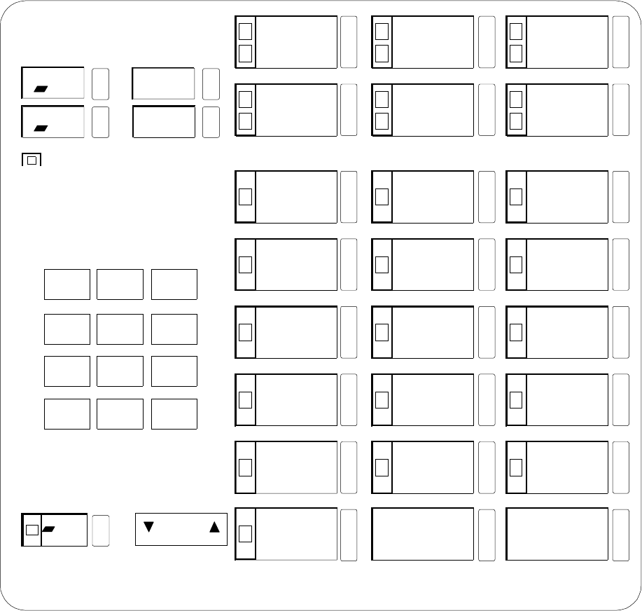
123
456
789
ABC DEF
MNOJKLGHI
PQRS TUV WXYZ
*
O#
Oper
MODEL NAME:_________________
The CALLMASTER II and CALLMASTER III Voice Terminal
Software Associate:_______________
Project Code:____________________
Customer Approval:_______________
Date:___________________________
Drop Test
Volume
Conference
Transfer
Hold
Select
Mute
Message
Ring
CALLMASTER
Log In Release
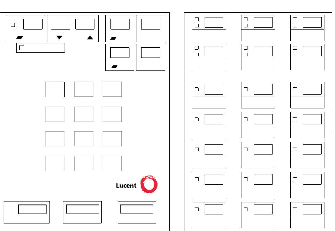
123
456
789
ABC DEF
MNOJKLGHI
PQRS TUV WXYZ
*
O#
Message
Ring Transfer
Conference
Test
Drop
Select Volume
ReleaseLog InMute
Hold
The CALLMASTER IV Voice Terminal
Software Associate: ____________________
Project Code: _________________________ Date: ______________________________
Customer Approval: __________________
MODEL NAME: ____________________
CALLMASTER IV
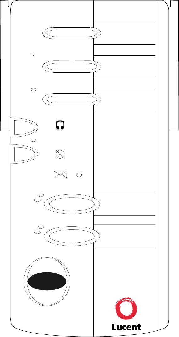
CALLMASTER VI
MODEL NAME:_________________
The CALLMASTER VI Voice Terminal
Software Associate:_______________
Project Code:____________________
Customer Approval:_______________
Date:___________________________
Headset On / Off
Mute
Message
a=
b=
Release
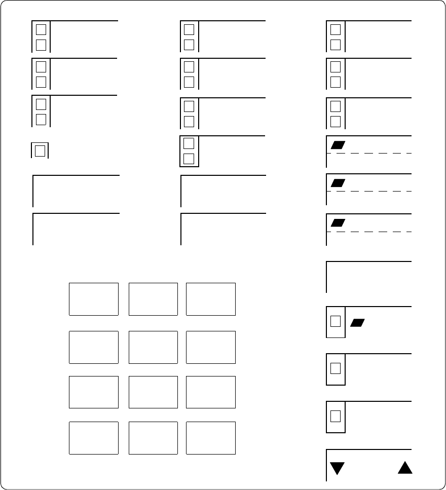
Conference
Drop
Transfer
Hold
Message
Ring
Test
Volume
123
456
789
ABC DEF
MNOJKLGHI
PRS TUV WXY
*
O
#
Oper
The ISDN 7505 Voice Terminal
MODEL NAME: ____________________
Software Associate: ____________________
Project Code: _________________________ Date: ______________________________
Customer Approval: __________________
Speaker
Mute
Select
Redial
Conference
Drop
Transfer
Hold
Message
Ring
Test
Volume
123
456
789
ABC DEF
MNOJKLGHI
PRS TUV WXY
*
O
#
Oper
The ISDN 7506 Voice Terminal
MODEL NAME: ____________________
Software Associate: ____________________
Project Code: _________________________ Date: ______________________________
Customer Approval: __________________
Speaker
Mute
Select
Redial
Data/Send/Off
Clock

Conference
Drop
Transfer
Hold
Speaker
Select
Mute
Message
The ISDN 7507 Voice Terminal
Software Associate: ____________________
Project Code: _________________________ Date: ______________________________
Customer Approval: __________________
MODEL NAME: ____________________
123
456
789
ABC DEF
MNOJKLGHI
PRS TUV WXY
*
O#
Oper
Volume
Ring
Test
Redial
Data/Send/Off
Clock
Message
123
456
789
ABC DEF
MNOJKLGHI
PQRS TUV WXYZ
*
O
#
OPER
Volume
Mute Redial
Program Memory
Conf Drop
Transfer Hold
TestRing
Pause
ab c
4
3
2
1
8
7
6
5
#
*
0
9
Press Memory button, then dialpad button
MODEL NAME:_________________
The ISDN 8503T Voice Terminal
Software Associate:_______________
Project Code:____________________
Customer Approval:_______________
Date:___________________________
Volume
Mute Redial
Speaker Exit
Conf Drop
Hold
123
456
789
ABC DEF
MNOJKLGHI
PQRS TUV WXYZ
*
O#
NextPrevMenu Dir
a
MODEL NAME:_________________
The ISDN 8510T Voice Terminal
Software Associate:_______________
Project Code:____________________
Customer Approval:_______________
Date:___________________________
b
c
d
e
f
g
h
i
j
Message
Transfer
Oper
123
456
789
ABC DEF
MNOJKLGHI
PQRS TUV WXYZ
*
O
#
Oper
Volume
Mute Redial
Speaker Exit
Conf Drop
Transfer Hold
a
b
c
d
e
f
g
h
i
j
ISDN 8520T
Dir
Next
Menu
Prev
k
l
m
n
o
p
q
r
s
t
Message
MODEL NAME:_________________
The ISDN 8520T Voice Terminal
Software Associate:_______________
Project Code:____________________
Customer Approval:_______________
Date:___________________________
