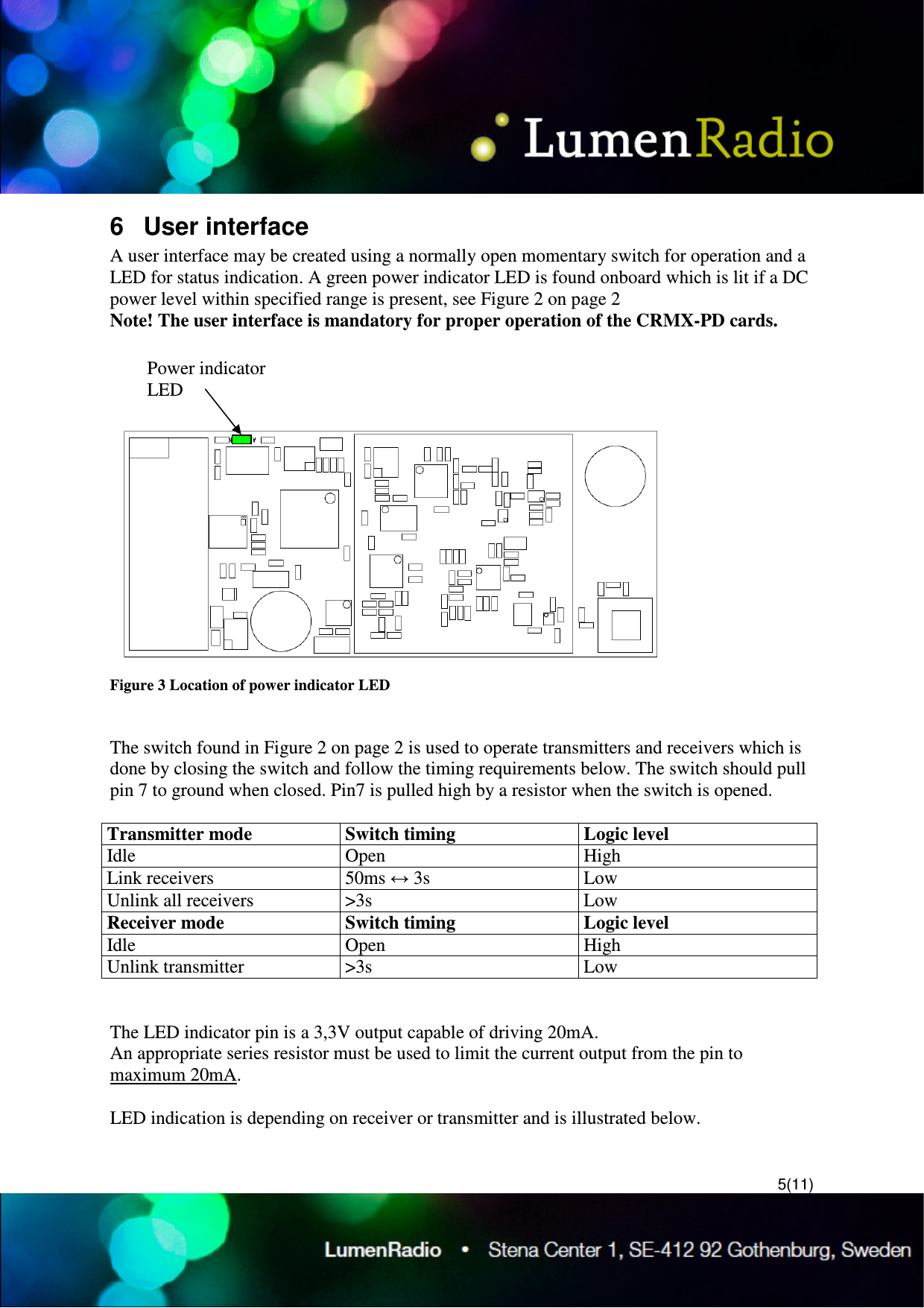
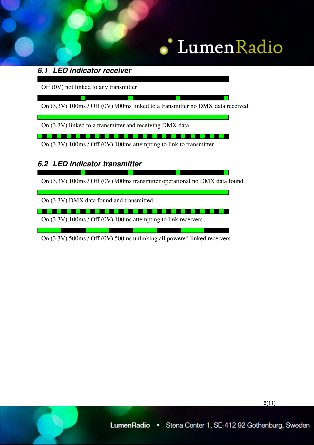
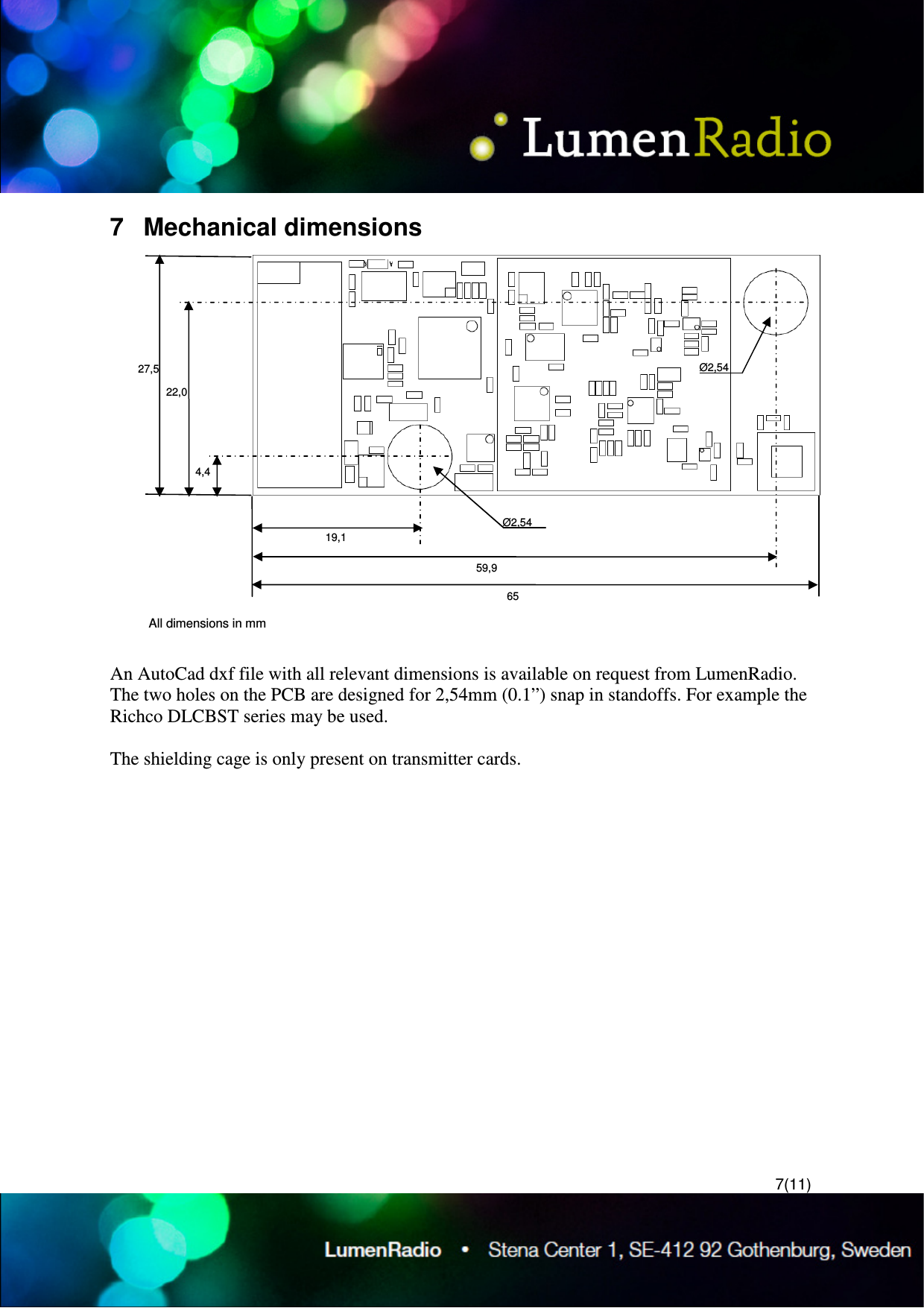
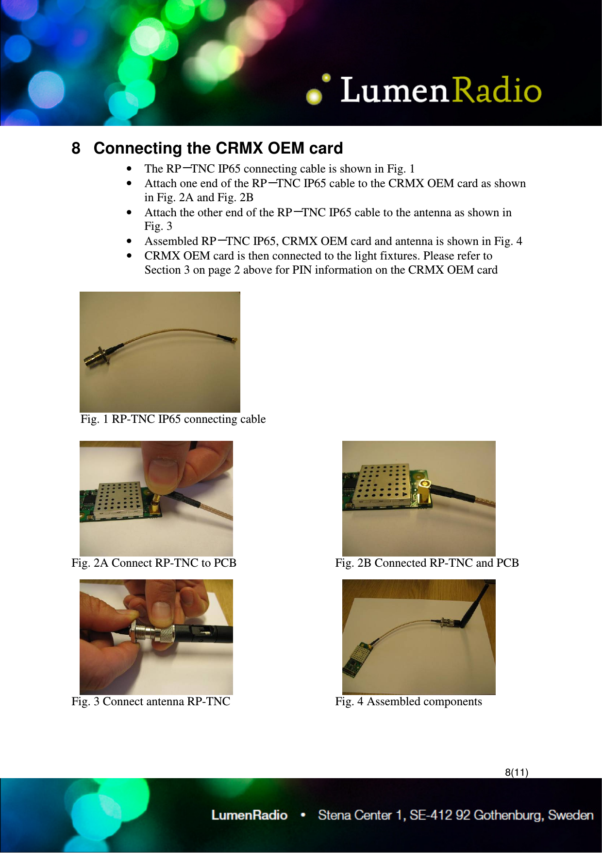
LumenRadio CRMXNOVA101 Wireless Light Control Module User Manual CRMX PD specification revC

LumenRadio AB Wireless Light Control Module CRMX PD specification revC

Users Manual

1(11) LumenRadio  CRMX-PD and -PR family DMX and RDM enabled transmitter and receiver modules. Rev. C – September 18, 2009  1  General The CRMX-PD family is the future of wireless DMX and RDM distribution – a wireless system that communicates reliably with perfect fidelity. CRMX-PD is the most powerful wireless lighting control system on the market, with ground breaking features to ensure unrivalled reliability. CRMX-PD distributes DMX and RDM with full frame integrity and provides range and reliability that surpass all other systems available today.  The CRMX-PD cards are designed to be small enough to fit into any standard fixture or controller and have an interface that easily connects to existing user interfaces. CRMX-PD cards are also compatible with W-DMX™ equipment for easy integration into legacy systems. CRMX™ is trademarked, patent pending, CE approved and FCC approval pending as of April 2009.   Two main families in the CRMX range of OEM products are found: • CRMX-PD, DMX enabled transmitter and receiver modules. • CRMX-PR, RDM enabled transmitter and receiver modules. 2  Features • Cognitive coexistence dynamically avoids occupied frequencies • Compliance with USITT DMX-512 (1986 & 1990) and 512-A • Full DMX fidelity and frame integrity • Auto sensing of DMX frame rate and frame size • <5ms DMX latency • W-DMX™1 compatible receiver • Standard 2,54 x 2,54mm (0,1 x 0,1”) 2x10 position interface connector • MCX type RF connector or optional integral antenna • All configuration data is stored in a non volatile memory, 20 year retention. • Up to 512 receivers may be used with every transmitter                                                  1 W-DMX™ is a trademark of Wireless Solution Sweden AB
 2(11) 3  Pinout  Figure 1 CRMX-PD/PR family DMX/RDM enabled PCB  Pin  Type  Description 1  Reserved  Do not connect, unimplemented feature 2  Reserved  Do not connect, unimplemented feature 3  Power  Unregulated DC input 6 - 12V   Warning! 4  Power  GND 5  Power  Regulated 5V   Warning! 6  O  Status LED output 7  I  Connect function switch input 8  I/O  DMX + 9  I/O  DMX - 10  Power  GND 11  O  PWM Red          (future implementation) 12  O  PWM Green      (future implementation) 13  O  PWM Blue         (future implementation) 14  I/O  SPI SCK             (future implementation) 15  I/O  SPI M ISO         (future implementation) 16  I/O  SPI MOSI          (future implementation) 17  I/O  SPI Slave Select optionally general I/O    (future implementation) 18  I/O  A/D converter 1 optionally general I/O    (future implementation) 19  I/O  A/D converter 2 optionally general I/O    (future implementation) 20  I/O  A/D converter 3 optionally general I/O    (future implementation) Warning! Do not connect power to pin 3 and 5 simultaneously. The card will be permanently damaged.  Pin 1 designator MCX type RF connector
 3(11) 4  Specifications   Min.  Typ.  Max.  Units DMX latency    5    ms Supported DMX frame rate receiver  1    8302  Hz Supported DMX frame rate transmitter  0,8    7352  Hz Unregulated low voltage input  6    12  VDC Regulated low voltage input  4,9  5,0  5,1  VDC Current consumption receiver    1303    mA Current consumption transmitter    2504    mA Function switch low level input      0,8  V Function switch high level input  2,0      V LED indicator voltage output    3,3V    V LED indicator current output      20  mA Frequency hopping rate    650    µs Operational frequency range  2402    2480  MHz RF output in high power mode    3005    mW RF output in normal power mode    100    mW RF output in low power mode    50 10   mW  mW Sensitivity at 0.1% Packet Error Rate    -96    dBm Recovery time upon loss of signal    <1    s Operating temp range (ambient)  -20 -4   +75 +167 °C °F  • Upon loss of DMX, transmitter module will timeout after 1,25s • Upon loss of RF link or DMX, receiver modules will go into high impedance state                                                    2 Limited by the DMX512-A standard 3 Both on regulated and unregulated input 4 Both on regulated and unregulated input 5 Allowed in US only
 4(11) 5  Typical application circuit  Figure 2 Typical application circuit Both the 120Ω and 4k7Ω resistors are required
5(11) 6  User interface A user interface may be created using a normally open momentary switch for operation and a LED for status indication. A green power indicator LED is found onboard which is lit if a DC power level within specified range is present, see Figure 2 on page 2 Note! The user interface is mandatory for proper operation of the CRMX-PD cards.   Figure 3 Location of power indicator LED   The switch found in Figure 2 on page 2 is used to operate transmitters and receivers which is done by closing the switch and follow the timing requirements below. The switch should pull pin 7 to ground when closed. Pin7 is pulled high by a resistor when the switch is opened.  Transmitter mode  Switch timing   Logic level Idle  Open  High Link receivers  50ms ↔ 3s  Low Unlink all receivers  >3s  Low Receiver mode  Switch timing   Logic level Idle  Open  High Unlink transmitter  >3s  Low   The LED indicator pin is a 3,3V output capable of driving 20mA.  An appropriate series resistor must be used to limit the current output from the pin to maximum 20mA.  LED indication is depending on receiver or transmitter and is illustrated below.  Power indicator LED
 6(11) 6.1  LED indicator receiver  6.2  LED indicator transmitter  Off (0V) not linked to any transmitter On (3,3V) 100ms / Off (0V) 900ms linked to a transmitter no DMX data received. On (3,3V) linked to a transmitter and receiving DMX data  On (3,3V) 100ms / Off (0V) 100ms attempting to link to transmitter On (3,3V) 100ms / Off (0V) 900ms transmitter operational no DMX data found. On (3,3V) DMX data found and transmitted. On (3,3V) 100ms / Off (0V) 100ms attempting to link receivers On (3,3V) 500ms / Off (0V) 500ms unlinking all powered linked receivers
 7(11) 7  Mechanical dimensions   An AutoCad dxf file with all relevant dimensions is available on request from LumenRadio. The two holes on the PCB are designed for 2,54mm (0.1”) snap in standoffs. For example the Richco DLCBST series may be used.  The shielding cage is only present on transmitter cards.   27,5 22,0 4,4 19,1 59,9 65 All dimensions in mm Ø2,54 Ø2,54
 8(11) 8  Connecting the CRMX OEM card • The RP-TNC IP65 connecting cable is shown in Fig. 1 • Attach one end of the RP-TNC IP65 cable to the CRMX OEM card as shown in Fig. 2A and Fig. 2B  • Attach the other end of the RP-TNC IP65 cable to the antenna as shown in Fig. 3 • Assembled RP-TNC IP65, CRMX OEM card and antenna is shown in Fig. 4 • CRMX OEM card is then connected to the light fixtures. Please refer to Section 3 on page 2 above for PIN information on the CRMX OEM card      Fig. 1 RP-TNC IP65 connecting cable  Fig. 2A Connect RP-TNC to PCB     Fig. 2B Connected RP-TNC and PCB Fig. 3 Connect antenna RP-TNC    Fig. 4 Assembled components
 9(11) 9  Testing the CRMX OEM In order to demonstrate the performance of the CRMX OEM in comparison with other wireless control devices, we recommend performing the following simple tests:  To demonstrate coexistence Reliable communication is possible because CRMX OEM neither interferes, nor is interfered by other WLAN equipment. To demonstrate, place two laptops next to a light fixture which has a CRMX OEM card installed. While the light fixture is in operation, digitally transfer a file between the two laptops via a wireless network. This utilises WLAN frequencies and the effects of interference can be observed during the transfer. With other wireless control devices, the transfer will be slow and jerky, or even impossible. However with the CRMX OEM installed, the transfer will be smooth, demonstrating that CRMX OEM does not interfere with other WLAN equipment, and that coexistence between the different devices exists.  - We recommend Windows Messenger or Windows File Sharer as a file transfer program. Transferring a file between two laptops, as opposed to streaming a  video on the Internet, is advised as this reduces complications arising from external factors such as Internet or website connectivity - A large file size is also recommended (>30MB) so that the transfer time is lengthened and the effects during the transfer can be observed more easily. - A larger number of laptops, as well as other WLAN devices such as routers and access points, may be used to simulate an environment with crowded radio frequencies.  To demonstrate full frame integrity Full frame integrity means that packets of data, or updates, are not lost during transmission. CRMX OEM ensures full frame integrity by using an error correction algorithm that is able to faithfully regenerate lost packets. There are two methods to demonstrate this:  1. Using LED lighting fixtures Set the LED lighting fixture with CRMX OEM to flash quickly. Connect a second identical LED fixture by cable to the same controller and same DMX start address. Because full frame integrity is supported, the LED lights respond with no delay compared to the wired LED fixture. However, with other wireless control devices, the difference in flashing speed of the fixture can be observed to be slower. Coupled with a latency of 5ms, the CRMX OEM is thus especially suitable for lighting fixtures where fast response times are required, such as LED lighting fixtures.  - LED light fixtures are used is because the response time of the LEDs are short, allowing for the effect of a lost packet to be observed.
 10(11) - Several LED light fixtures may be used so that any lost packets can be easily detected when the lights are seen to be out of sync.  2. Using 16-bit lighting fixtures or lighting fixtures with multiplexing  Full frame integrity can also be observed in lighting fixtures that use 16-bit pan and tilt controls or multiplexing. A lost packet will be clearly noticeable in the form of jerky movements of the fixture. Being built to be compatible with future lighting fixtures, CRMX OEM ensures reliable wireless controls. As advanced lighting fixtures using 16-bits and multiplexing become increasingly sought after, CRMX OEM is ready to support them every step of the way.  - 16-bit lighting fixtures or fixtures with multiplexing functions are used as the effects of a lost package is more significant and hence easier to observe
 11(11) 10 Ordering Information Ordercode  Description PDRI-1  LumenRadio CRMX™ DMX receiver with integral antenna PDRE-1  LumenRadio CRMX™ DMX receiver with MCX type RF connector PDTI-1  LumenRadio CRMX™ DMX transmitter with integral antenna PDTE-1  LumenRadio CRMX™ DMX transmitter with MCX type RF connector PRRI-1  LumenRadio CRMX™ DMX/RDM receiver with integral antenna PRRE-1  LumenRadio CRMX™ DMX/RDM receiver with MCX type RF connector 11 Revision history Revision  Release date   Data sheet status  PA2  2009-03-30   Modifications:  --- A  2009-04-07  Production Modifications:  1. Chapter 3 Pinout, function switched moved from pin 19 to pin 7 2. Figure 2 Typical application circuit, function switch B  2009-05-28  Production Modifications:  1. Chapter 3 Pinout, additional pin specification details added. C  2009-09-18  Production Modifications:  1. Chapter8 Connecting the CRMX OEM card added 2. Chapter 9 Testing the CRMX OEM added 3. Chapter 10 Ordering Information, order codes for RDM versions added

Navigation menu