Lumenetix CTM Color Tuning Module User Manual
Lumenetix Inc Color Tuning Module
User Manual

the true and perfect light
araya® LED Light Engine
CTM 012 CTM 019 CTM 032
Installation Guide
TABLE OF CONTENTS
1 Introduction 2
2 Heat Sinking 3
2.1 Compatible Heat Sinks
2.2 Mechanical Attachment of the Heat Sink
3 CTM Case Temperature Measurement 5
4 Secondary Optics 6
4.1 CTM 012 Reflectors
4.2 CTM 019 Reflectors
4.2.1 Attaching Reflectors
4.2.2 Compatible Reflectors
5 Power Supplies 8
6 Wiring Diagrams 9
6.1 Wiring diagrams for Wireless
6.2 Wiring diagrams for Wireless with unit syncing
6.2 Wired and Hybrid (wireless and wired) Operation

araya® LED Light Engine Installation Guide | 2
This Installation Guide covers the following araya® Color Tuning Modules (CTM):
• CTM 012
• CTM 019
• CTM 032
For complete Color Tuning Module specifications, please visit: www.lumenetix.com/downloads
This Installation Guide covers heat sinking, case temperature measurement, secondary optics, power supply and wiring diagrams
for wireless operation using the Lumenetix Light Commissioning Tool, industry standard 0-10V wired controls or a hybrid
operation that combines hard wired and wireless control.
The CTM Source diffuser is fragile. Avoid touching the diffuser during
handling and assembly.
For long term, reliable operation, proper heat sinking is critical.
1 INTRODUCTION
2 HEATSINKING
The CTM light module requires an external heat sink in order to ensure proper operating temperature of the LEDs. The CTM
has a conductive aluminum case and an efficient thermal path to the LED array. These features promote efficient thermal
management and allow for a simple heat sink design in most applications.
Examples of heat sinking methods are: cast or extruded heat sinks, an aluminum panel or aluminum fixture housing. Both
carbon and stainless steel are much less efficient at transferring heat than aluminum and therefore are not recommended as
heat sink material. The heat sink mounting surface should be flat and smooth. Metal-to-metal contact surfaces will result in best
performance; anodized or unfinished mounting surfaces are recommended. Mounting the CTM on a painted aluminum surface
will reduce the performance of the heat sink material.
2.1 Compatible Heat Sinks
The following tables list heat sinks models that have compatible form factors and thermal resistance characteristics for use
with the CTM. The thermal resistances assume an approximate ambient temperature of 25C. The heat sinks listed here
are suggestions only. The heat sink must be evaluated and temperature tested in the fixture application at applicable
ambient temperatures.
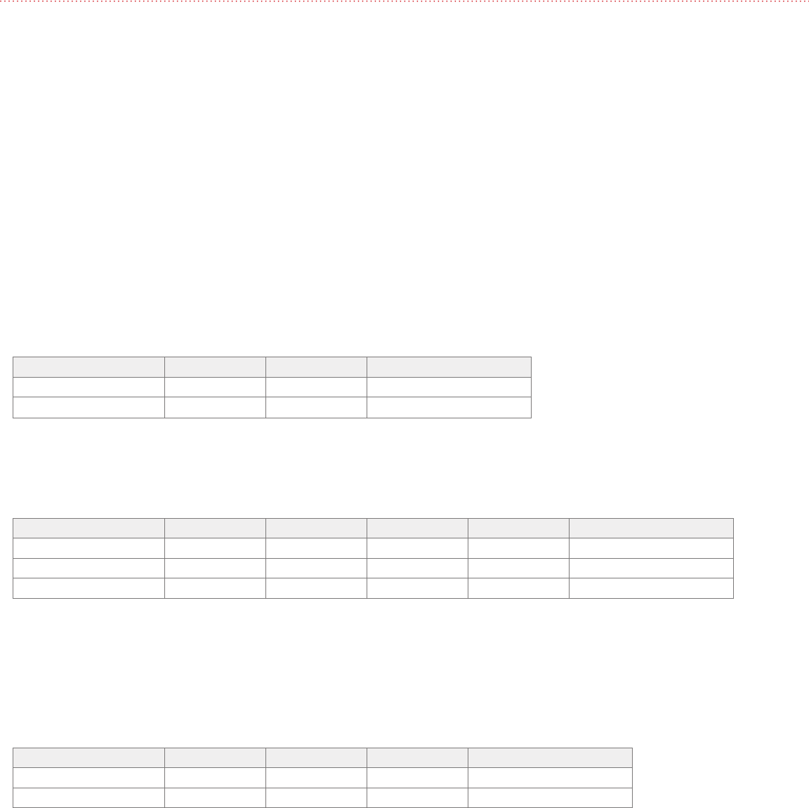
MechaTronix (round)
Part Number Dia. (mm) Height (mm) Thermal Resistance (°C/W)
LSB9950 99 50 1.3 – 1.5
LSB9980 99 80 1.2 – 1.4
Additional product information at www.led-heatsink.com
Nuventix (round)
Part Number Description Input Voltage Dia. (mm) Height (mm) Thermal Resistance (°C/W)
HP30S-CALBL-001 Heat Sink 95 39 2.5 (heat sink only)
SPARS-CM005-002 (1) Cooler 5V 1.0 – 1.55
SPARS-CM012-002 (1) Cooler 12V 1.0 – 1.55
Additional product information at www.nuventix.com
No current commercial 24V power supply offerings with dual voltage out for Nuventix Synjet cooler (24V out w/ 5V or 12V out).
Requires DC/DC voltage adaptor without dual voltage output.
Aavid Thermalloy Heat Sink Extrusions (square/rectangular)
Part Number Width (mm) Length Height (mm) Thermal Resistance (°C/W)
67590 88 88 31 1.5 – 1.7
61085 136 85 33 1.4 – 1.6
Additional product information at www.aavid.com
araya® LED Light Engine Installation Guide | 4
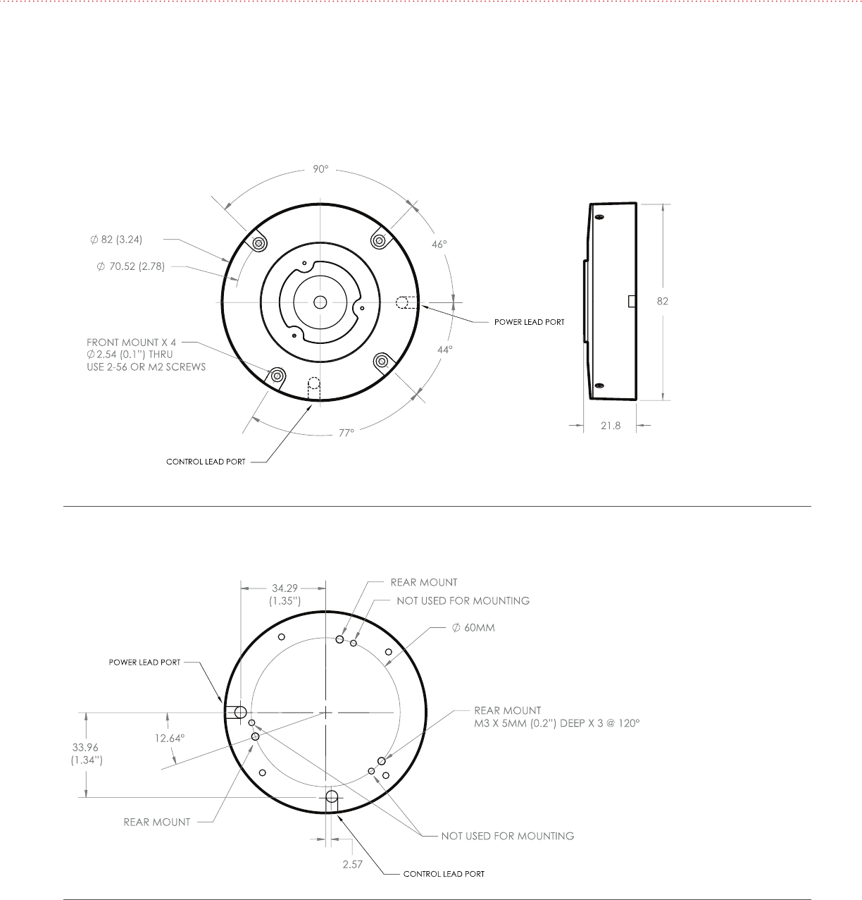
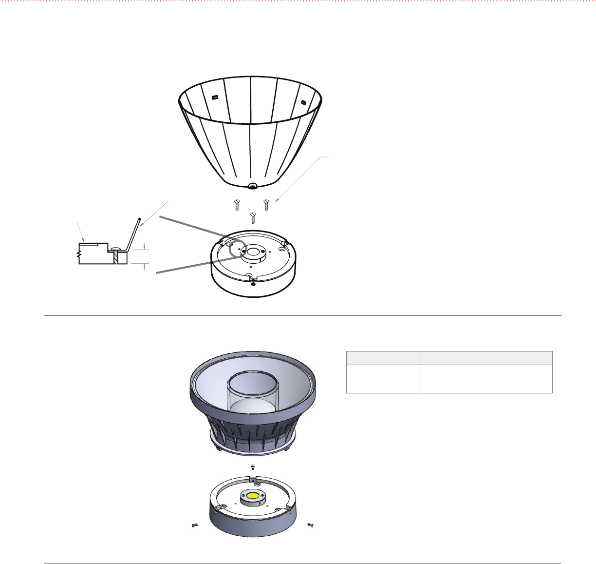
2.2 Mechanical Attachment of the Heat Sink
The CTM light engine has two options for heat sink mounting:
1. Front mount using four 2-56 or M2 screws
2. Rear mount using three M3 screws
NOTE: CTM 019 shown, Drawing also applies to CTM 012 & CTM 032.
NOTE: SOME HOLES NOT SHOWN FOR CLARITY.
Figure 1: Front Mount of CTM to Heat Sink
Figure 2: Rear Mount of CTM to Heat Sink
The thermal management characteristics of the heat sink used with the CTM should be validated by measuring its case
temperature. This test should be done with the CTM installed in the fixture at ambient temperature and air flow conditions similar
to the end-use installation.
araya® CTMs are available with two ranges: 1600 – 4000K and 2700 – 6000K. The power draw of the CTM varies by approximately
one watt over the CCT range with peak power draw occurring at the CCT shown in the following table. Depending on the CCT
range, the case temperature should be measured at the following CCT setting.
CCT Setting for Case Temperature Measurement
CTM CCT range CCT Setting to Measure Tcase
1600 – 4000K 2800K
2700 – 6000K 3600K
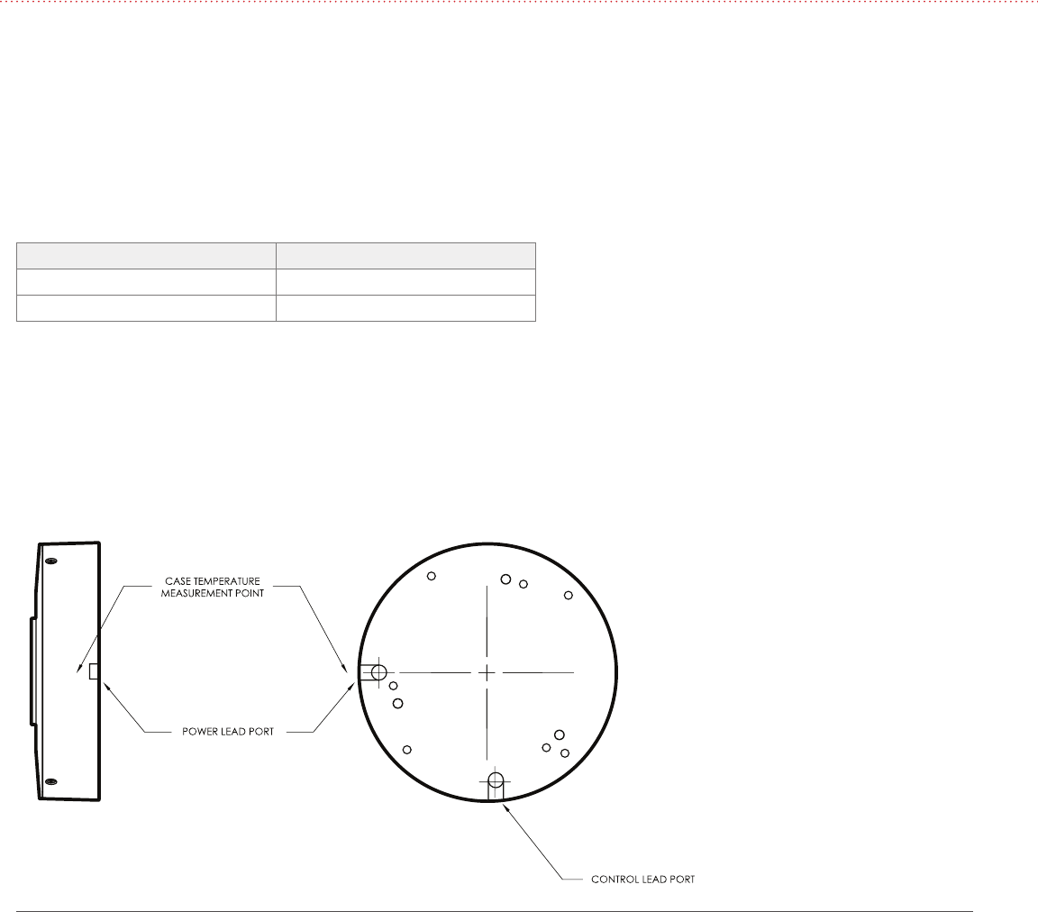
The proper case temperature measurement location is next to the exit for the power leads, see Figure 3. The temperature reading
should be made after the unit has reached steady state, where the case temperature levels out. It is recommended to design for a
case temperature of 70° C at maximum ambient temperature conditions
The CTM color tuning module has built-in over-temperature protection. It is designed to turn down the current to the LED array
when the case temperature reaches 75° C. This ensures the LEDs don’t exceed their maximum rated temperature.
3 CTM CASE TEMPERATURE MEASUREMENT
Figure 3: Case Temperature Measurement Point
araya® LED Light Engine Installation Guide | 6
4.1 CTM 012 Reflectors
The CTM 012 accepts the Lumenetix sReflector and mReflectors and has attachment features to accept other reflectors.
4 SECONDARY OPTICS
Figure 5: Side Mount Attachment of the sReflector and the mReflector
Figure 4: CTM 012 Front Attaching Reflectors
NOTE: mReflector shown,
assembly similar for sReflector
REFLECTOR
M1.8
THREAD FORMING
SOURCE APERTURE
5 mm (0.187")
Reflector Type Fastener Specification
sReflector 0 – 80 x ¼" Flathead
mReflector M1.8 x 6 Thread Forming Flathead
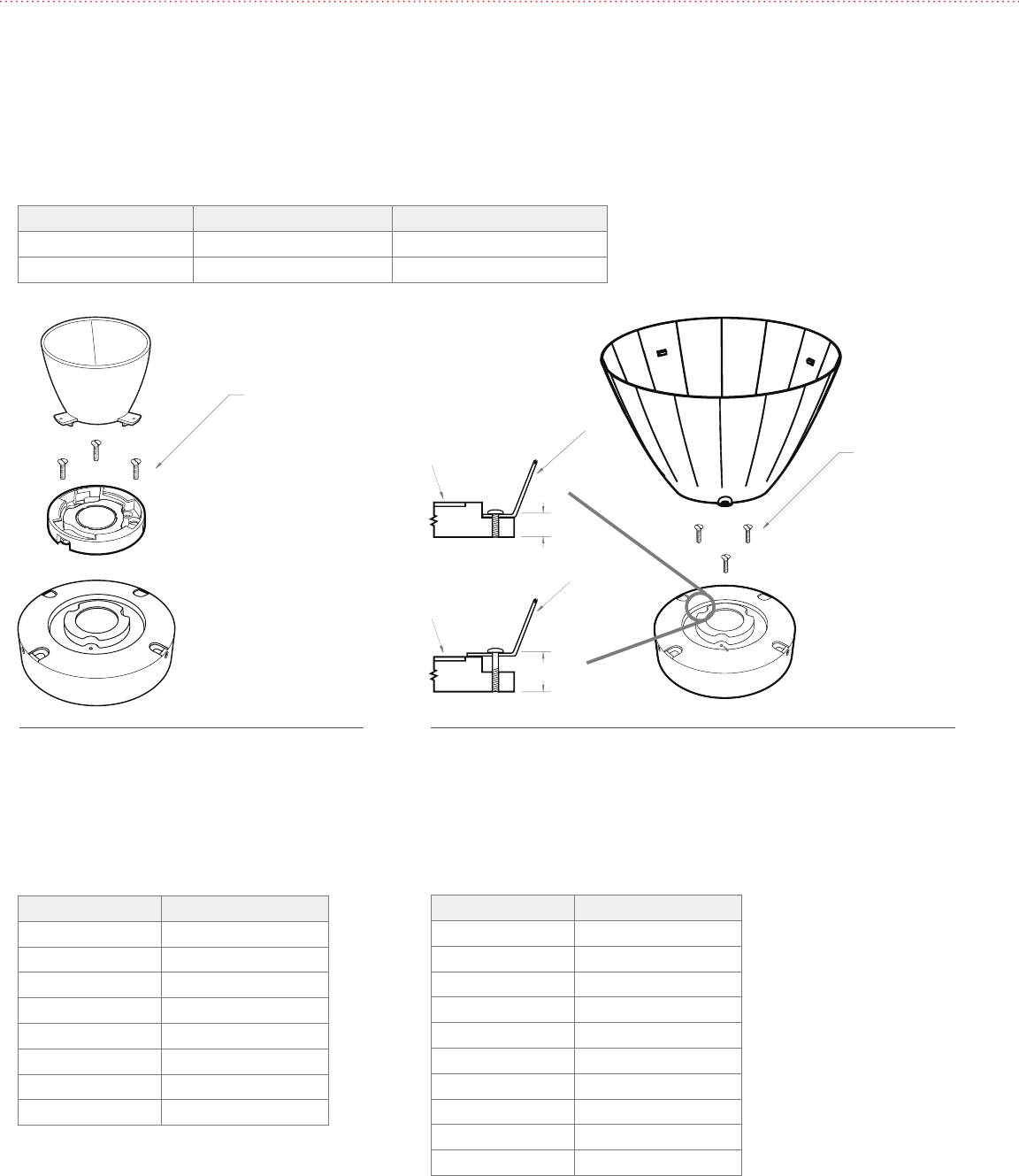
4.2 CTM 019 Reflectors
4.2.1 Attaching Reflectors
The CTM 019 accepts the twist-to-lock reflectors with an attachment collar. The module also has provisions for front mount
reflectors. The fastener specifications are shown in the following table while mounting hole locations are shown in Figures 6 & 7.
CTM 019 Secondary Optics Fastener Specifications
CTM 019 Reflector Fastener specifications Screw length
Twist Lock w/ Collar 2 - 28 x 3/16, M1.8 x 5 5 mm (3/16")
Front Mount 2 - 28, M1.8 5 mm (3/16") or 10 mm (3/8")
M1.8 x 5, 2 - 28 x 3/16
THREAD FORMING
USE FLAT HEAD SCREWS REFLECTOR
SOURCE APERTURE
REFLECTOR
5 mm (0.187")
10 mm (0.375")
SOURCE APERTURE
2 - 28 OR M1.8
THREAD FORMING
Figure 6: CTM 019 Twist-Lock Style Reflectors with
attachment collars
Figure 7: CTM 019 Front Attaching Reflectors
4.2.2 Compatible Reflectors
CTM 019 Recommended Twist-Lock Reflectors
Vendor: Diffractive Optics
Part Number Beam Angle (degrees)
P4769 40
P6643 20
P6680 40
P6645 60
P6762 40
P6764 60
P7076 20
P8669 25
CTM 019 Recommended Front Mount Reflectors
Vendor: Alum-Luxar
Part Number Beam Angle (degrees)
XLC 100 16
XLC 400 28
XLC 1000 14
XLC 110 0 27
XLC 200 Diffuse 18
XLC 500 28
XLC 800 14
XLC 110 0 27
XLC 1300 22
XLC 1400 25
araya® LED Light Engine Installation Guide | 8
Recommended Power Supplies
Vendor: Philips
Part Number Qty of CTMs Powered Input Voltage Connection type
LED120A0024V14F 1120 V Flying leads
913700625082 1 207V – 264V Flying leads
LED120A0024V18F 1120V Terminal block
INTA0024V28FLO 2 120V – 277V Flying leads
INTA0024V41FO 3 120V – 277V Flying leads
Notes:
1. Philips does not offer a 120V – 277V driver to power one (1) CTM
2. At the time of document release, Philips does not offer a cooler with dual voltage out for (24V out w/ 5V or 12V out).
Requires DC/DC voltage adaptor without dual voltage output.
Vendor: Osram Sylvania
Part Number Qty of CTMs Powered Input Voltage Connection type
OT30/120/24 1120 V Flying leads
OT75W/24V/UNV 2120 – 277 V Flying leads
OT75W/24V/UNV 3120 – 277 V Flying leads
5 POWER SUPPLY REQUIREMENTS
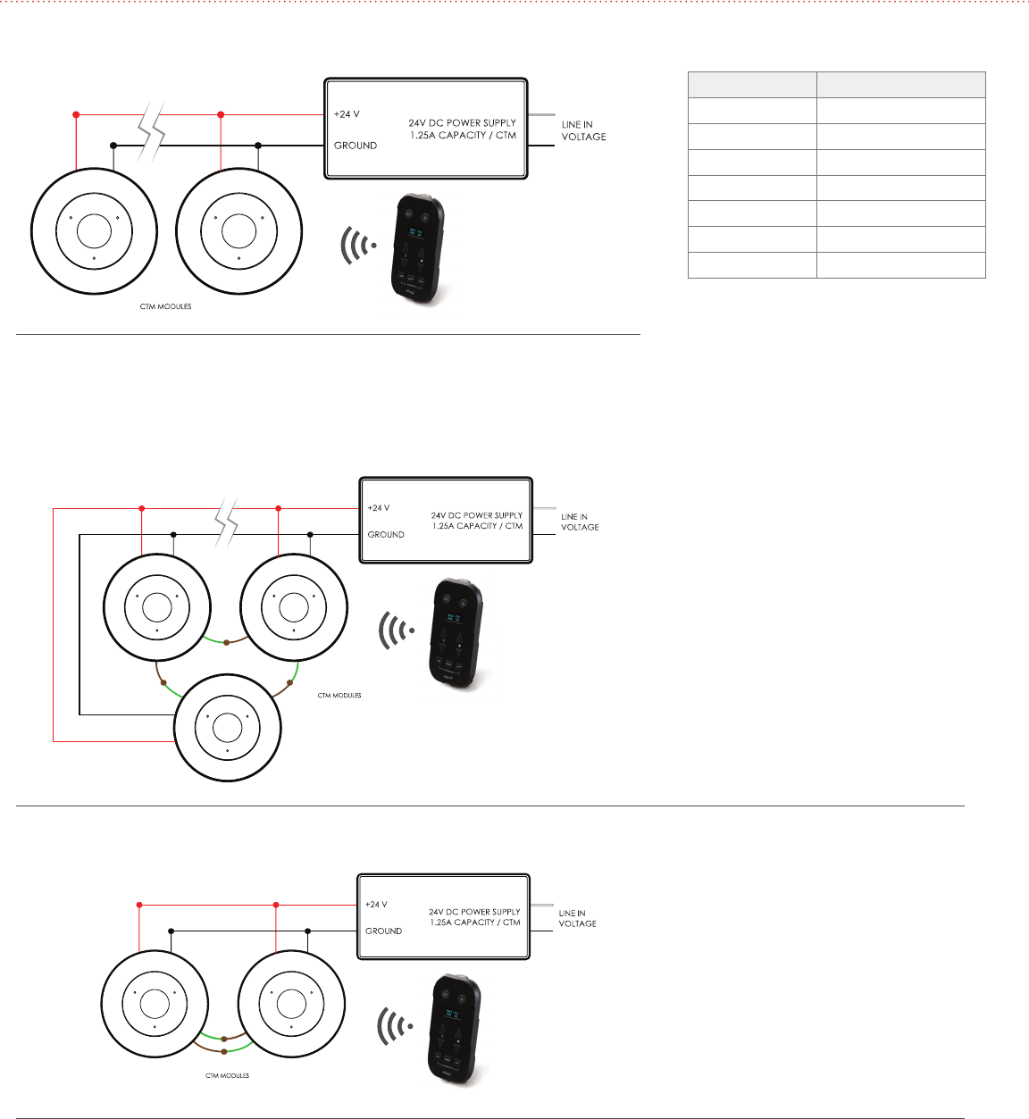
Lead Color and Input
Lead Color Input
Red +24V DC
Black -24V DC
Purple 0-10V CCT
Gray Common
Blue 0-10V Dimming
Green Unit Synching - Tx
Brown Unit Synching - Rx
6 WIRING DIAGRAMS
Figure 8: Wireless Operation Using the Light Commissioning Tool (LCT)
6.1 Wiring diagrams for Wireless
Figure 9: Wireless Operation Using the LCT, Syncing 3 or more units.
Figure 10: Wireless Operation Using the LCT, Syncing 2 units.
6.2 Wiring diagrams for Wireless with Unit Syncing
araya® LED Light Engine Installation Guide | 10
CCT
LCT
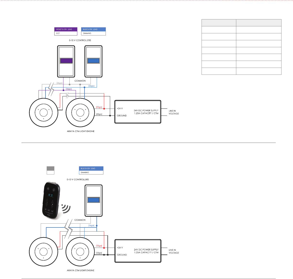
Figure 11: Wired Operation Using 0-10V Wired Controls
Figure 12: Hybrid Operation, Wireless Control of CCT, 0-10V Control of Dimming
6.3 Wired and Hybrid (wireless and wired) Operation Lead Color and Input
Lead Color Input
Red +24V DC
Black -24V DC
Purple 0-10V CCT
Gray Common
Blue 0-10V Dimming
Green Unit Synching - Tx
Brown Unit Synching - Rx

araya®
LED Light Engine Installation Guide | 11
Federal Communication Commission Interference Statement
This device complies with Part 15 of the FCC Rules. Operation is subject to the following two
conditions: (1) This device may not cause harmful interference, and (2) this device must accept
any interference received, including interference that may cause undesired operation.
This equipment has been tested and found to comply with the limits for a Class B digital
device, pursuant to Part 15 of the FCC Rules. These limits are designed to provide reasonable
protection against harmful interference in a residential installation. This equipment generates,
uses and can radiate radio frequency energy and, if not installed and used in accordance with
the instructions, may cause harmful interference to radio communications. However, there is
no guarantee that interference will not occur in a particular installation. If this equipment
does cause harmful interference to radio or television reception, which can be determined by
turning the equipment off and on, the user is encouraged to try to correct the interference by
one of the following measures:
- Reorient or relocate the receiving antenna.
- Increase the separation between the equipment and receiver.
- Connect the equipment into an outlet on a circuit different from that to which the receiver is
connected.
- Consult the dealer or an experienced radio/TV technician for help.
FCC Caution: Any changes or modifications not expressly approved by the party responsible
for compliance could void the user's authority to operate this equipment.
This transmitter must not be co-located or operating in conjunction with any other antenna or
transmitter.
This device complies with Part 15 of the FCC Rules. Operation is subject to the following two
conditions:
(1) This device may not cause harmful interference, and
(2) this device must accept any interference received, including interference that may cause
undesired operation.
FCC ID: Q8A-CTM

Lumenetix Inc.
4742 Scotts Valley Drive
Scotts Valley CA 95066
877. 8 05.7 28 4
www.lumenetix.com