Lumi IML-CONN-1 IML Connector User Manual IML Connector
Lumi Technologies Limited IML Connector IML Connector
UserManual.wiki
>
Lumi
>
IML CONN 1 User Manual
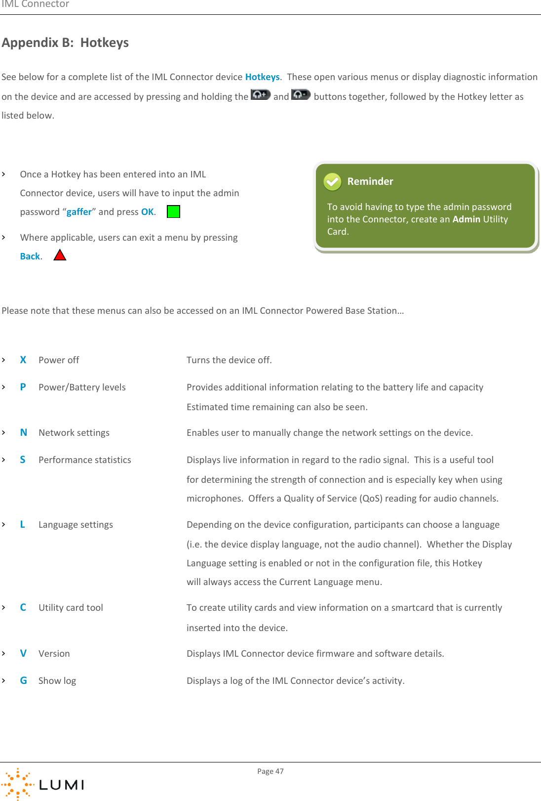
Users manual
Navigation menu
Upload a User Manual
Namespaces
Wiki Guide
HTML
PDF
Info
Views
User Manual
Discussion / Help
Navigation

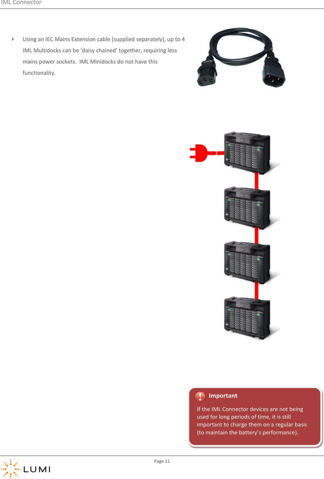
![IML Connector Page 48 Appendix C: Glossary of Terms A/B USB cable Common USB data connection for devices to connect to a PC. Accelerometer Device which measures acceleration, usually associated with detecting movement of the IML Connector device. Alarm Proximity alarm on each IML Connector device which can be enabled to activate shortly after once the device has disconnected frin the Base Station (i.e. goes out of range). Attendance Tracking Feature which marks participants as present once they have inserted the IML Smartcard into an IML Connector. Time period can be set by the operator. Application The term used for a software program, which can [usually] be installed and/or run from a PC. Audio Routing An audio configuration which provides for multiple scenarios and various levels of audio use. Bandwidth Rate of data transfer, bit rate or throughput. Base Station IML Connector handset which connects to the PC and communicates wirelessly with other IML Connector devices. Battery Hardware device which converts chemical energy into electrical energy. Each IML Connector device contain a rechargeable Lithium Ion battery. Boot Up The period of time whilst a device is turning on initialising before it can be used. Configuration File Programmable file which is deployed to IML Connector devices and manages settings such as power, language and customisable content. Control PC Term used for the PC which is used to connect a Base Station to and control IML Connector devices. Lumi applications installed and used on the PC control this. Countdown Clock Timer used to show audience when vote is open and how long remaining. Custom Screen A customisable screen which is included in the IML Connector configuration file. Can usually be accessed by participants or displayed on devices by the operator. Daisy Chain Term used when devices are connected to each other in linear formation, as opposed to in a star. Default Network User Driven Roaming, the network appearing at the top of the list, which an IML Connector device connects to if restarted. Can’t be secured with a password. Delegate Mic The standard microphone functionality available on the IML Connector device. Deploy To ‘burn’ or copy a configuration file onto an IML Connector device Display screen Electronic visual display device built into each IML Connector. Docked Term used to indicate that an IML Connector device is inserted into the docking device. Docking device IML Multidock or IML Minidock, hardware for storing, charging or connecting IML Connector devices to a PC. Dongle Small piece of hardware which attaches to a PC (usually by USB). Term commonly used for a Lumi USB HASP licence. Drivers Configuration files needed for a PC to communicate with hardware.](https://usermanual.wiki/Lumi/IML-CONN-1/User-Guide-3314423-Page-48.png)
![IML Connector Page 49 Facilitator Mic An additional micrphone in an IML Connector system which is provided by inserting a utilty card. Firmware A software program or set of instructions programmed on a hardware device. Gigabyte (GB) A multiple of the ‘byte’ digital data storage unit (1 GB = 1,024 Megabytes) Global If referring to a setting or action, implies all IML Connector devices will be affected. Handset Alternative term for an IML Connector device, or keypad. Hardware Collection of physical components which comprise a system. Headphones Small pair of loudspeakers designed to be held in place close to a user’s ears. Third party audio hardware which can be connected to an IML Connector device. Hirose Data connection type built into each IML Connector device. Home Screen Default screen displayed on the IML Connector device during perios of no use or activity. Hotkey Button(s) used to quickly access a menu or setting on the IML Connector device. IEC International Electrotechnical Commission, a standard of common, three-pin power connection. IML Connector Configuration Tool Application to create and deploy configuration files to IML Connector devices. IML Connector device An IML Connector wireless handset, or keypad IML Connector System The IML hardware and Lumi software system as a whole, usually including the control PC, all IML Connector devices and a Base Station. IML Connector System Manager Application to monitor and control the IML Connector System IML Minidock Docking device for up to 10 IML Connector devices. Provides charging and USB connectvity. IML Multidock Docking device for up to 50 IML Connector devices. Provides charging and USB connectvity. IML Multidocks can be ‘daisy-chained’ by up to four devices for power or data connections. IML Smartcard Chip card which can be programmed to identify participants or carry out administrator tasks on IML Connector devices. Index Number Programmable number on each IML Connector device used for identification purposes. Keypad Alternative term for an IML Connector device, or handset. Can also refer to the actual keyboard and buttons on the front of the IML Connector device. Latch Microphone mode where the Microphone key is pressed once to open and again to close the microphone. LED A Light-Emitting Diode is a [usually] small, low energy, light source. Licence End user licence for Lumi software and hardware, provided via use of a USB HASP licensing ‘dongle’. Light sensor Hardware on the front of the IMl Connector device which can be configured for IML Connector devices to use and set optimum screen brightness.](https://usermanual.wiki/Lumi/IML-CONN-1/User-Guide-3314423-Page-49.png)