Lutron Electronics 0032 Radio Frequency Controlled Dimmer User Manual 044 008a RA 600LM
Lutron Electronics Company Inc Radio Frequency Controlled Dimmer 044 008a RA 600LM
Users Manual
Important Notes
1. Caution: To avoid overheating and possible
damage to other equipment, do not use to control
receptacles, fluorescent lighting fixtures, motor-
operated or transformer-supplied appliances.
2. Install in accordance with all national and local
electrical codes.
3. Do not paint dimmers or wallplates.
4. Clean with a
soft damp cloth only
. Do not use any
chemical cleaners.
5. Do not use where total wattage is under
recommended minimum load.
6. Do not exceed maximum load rating of dimmers.
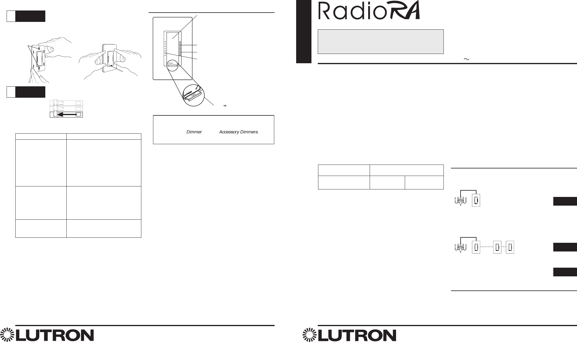
7. In any 3-way/4-way circuit use only one
Dimmer
with
up to 9
Accessory Dimmers
.
8. Dimmer may not work with dioded lamps (Sylvania
Designer 16™ or Philips PAR-16™).
9. Operate in ambient temperatures between 0°C
(32°F) and 40°C (104°F).
10. Dimmer may feel warm to the touch during normal
operation.
11. Recommended wallbox depth: 31/2" deep
recommended, 21/2" deep minimum.
12. The range and performance of the RadioRA® System
is highly dependent on a variety of complex factors
such as:
• Distance between system components
• Geometry of the home
• Construction of walls separating system components
• Electrical equipment located near system components
13. Do not mix RadioRA®“A”(RA-) and “B” (RB-)
products within the same system. “A” products and
“B” products
are not
compatible.
Installation Instructions for
Multi-Location Control
Please Leave for Occupant
Incandescent / 120V Halogen / Magnetic
Low-Voltage
RA-6D, RB-6D
RA-10D, RB-10D
Accessory Dimmer
RA-AD, RB-AD
120 V 50/60 Hz
Low-Voltage dimmers only:
14. Use models RA/RB-6D/10D with only core and coil
(magnetic) low-voltage transformers. Do not use to
control solid-state (electronic) low-voltage
transformers.
15. CAUTION: Operating a dimmed low-voltage circuit
with all lamps inoperative or removed may result in
current flow in excess of normal levels. To avoid
possible transformer overheating and premature
failure, Lutron strongly recommends the following:
• Do not operate dimmed low-voltage circuits without
operative lamps in place.
• Replace burned-out lamps immediately.
• Use transformers with thermal protection or fused
primary windings to prevent transformer failure due
to excess current.
Before installation read instructions
completely.
Minimum Load Chart
Dimmer Wattage
Type of Load 600W 1000W
Incandescent 50 W 50 W
Magnetic Low-Voltage 50 VA 100 VA
English
P/N 044-050
Lutron Electronics Co., Inc.
7200 Suter Road
Coopersburg, PA 18036-1299, U.S.A.
Made and printed in the U.S.A. 7/04 P/N 044-050 Rev. A
Operation
Three-Location Installation Continued
FCC Information
NOTE: This equipment has been tested and found to comply with the limits
for a Class B digital device, pursuant to part 15 of the FCC rules. These
limits are designed to provide reasonable protection against harmful
interference in a residential installation. This equipment generates, uses and
can radiate radio frequency energy and, if not installed and used in
accordance with the instructions, may cause harmful interference to radio or
television reception, which can be determined by turning the equipment off
and on, the user is encouraged to try to correct the interference by one or
more of the following measures:
• Reorient or relocate the receiving antenna.
• Increase the separation between the equipment and receiver.
• Connect the equipment into an outlet on a circuit different from that
to which the receiver is connected.
• Consult the dealer or an experienced radio/TV technician for help.
Caution: Changes or modifications not expressly approved by Lutron
Electronics Co. could void the user's authority to operate this equipment.
Operation is subject to the following two conditions: (1) This device may not
cause harmful interference, and (2) this device must accept any interference
received, including interference that may cause undesired operation.
Technical Assistance
If you have questions concerning the installation or operation of this
product, call the
Lutron Technical Support Center.
Please provide
exact model number when calling.
(800) 523-9466 (U.S.A., Canada, and the Caribbean)
Other countries call (610) 282-3800
Fax (610) 282-3090
Visit our web site at www.lutron.com
Step 7 Mount and align dimmers. Attach
Claro® or Satin ColorsTM wallplates
(purchased separately).
Step 8 Turn power ON.
Align dimmers.
Ensure FASSTM
switches are
fully pushed in.
Tighten
screws until
snug. Attach wallplates.
ON
OFF
ON
OFF
ON
OFF
Troubleshooting
Possible Cause
• Front Accessible Service Switch
(FASSTM) on the dimmers are
pulled out (OFF).
• Light bulb(s) burned out.
• Breaker is off or tripped.
• Blue wire on
Accessory Dimmer
not connected to the same color
wire as the blue wire on
Dimmer.
• Black and Red wires on
Dimmer
are reversed.
•
Dimmer
wired in middle of
Accessory Dimmer
string - must
be on the line or load end of
string.
• Total wattage is under
recommended minimum load.
(See Important Note No.5.)
Symptom
Light does not turn on.
Light turns ON and
Dimmer
works, but
Accessory Dimmer
does not work.
Switch
Tap on, Tap off
Tap Twice Quickly - lights
adjust rapidly to full.
Press & Hold for 2 Seconds
- Activates 10 second
fade to off.
Dimming Rocker
Brighten
Dim
LEDs
Indicate light level; glow
softly as night light when
light is off. (Not available on
Accessory Dimmer.)
FASS
Front Accessible Service
Switch
For detailed instructions on programming the
system, refer to the RadioRA
®
Setup Guide that
is included with an RF Signal Repeater or the
Setup and Installation Guide that is included
with a Chronos System Bridge and Timeclock.
IMPORTANT NOTICE:
FASS™ - Front Accessible Service Switch - to replace bulb,
power may be conveniently removed by pulling FASS switch
out on both the and any
For any procedure other than routine lamp replacement,
power must be disconnected at the main electrical panel.
Limited Warranty
Lutron will, at its option, repair or replace any unit that is defective in materials or manufacture
within two years after purchase. For warranty service, return unit to place of purchase or mail
to Lutron at 7200 Suter Rd., Coopersburg, PA 18036-1299, postage pre-paid.
THIS WARRANTY IS IN LIEU OF ALL OTHER EXPRESS WARRANTIES, AND THE IMPLIED
WARRANTY OF MERCHANTABILITY IS LIMITED TO TWO YEARS FROM PURCHASE.
THIS WARRANTY DOES NOT COVER THE COST OF INSTALLATION, REMOVAL OR
REINSTALLATION, OR DAMAGE RESULTING FROM MISUSE, ABUSE, OR IMPROPER OR
INCORRECT REPAIR, OR DAMAGE FROM IMPROPER WIRING OR INSTALLATION. THIS
WARRANTY DOES NOT COVER INCIDENTAL OR CONSEQUENTIAL DAMAGES. LUTRON’S
LIABILITY ON ANY CLAIM FOR DAMAGES ARISING OUT OF OR IN CONNECTION WITH
THE MANUFACTURE, SALE, INSTALLATION, DELIVERY, OR USE OF THE UNIT SHALL
NEVER EXCEED THE PURCHASE PRICE OF THE UNIT.
This warranty gives you specific legal rights, and you may also have other rights which vary from
state to state. Some states do not allow limitations on how long an implied warranty lasts, so the
above limitation may not apply to you. Some states do not allow the exclusion or limitation of
incidental or consequential damages, so the above limitation or exclusion may not apply to you.
This product may be covered under one or more of the following U.S. patents:4,835,343;
4,954,768; 5,248,919; 5,399,940; 5,637,930; 5,736,965; 5,798,581; 5,838,226; 5,848,054;
5,905,442; 5,982,103; 6,687,487; DES 353,798; DES 378,814; DES 389,461; DES 389,805;
DES 395,037; DES 404,013; DES 422,969; DES 428,855; DES 436,579, DES 439,220 and
corresponding foreign patents. U.S. and foreign patents pending. Lutron, Claro, and RadioRA
are registered trademarks, and FASS is a trademark of Lutron Electronics Co., Inc.
© 2004 Lutron Electronics Co., Inc.
Dimmer
keeps turning
ON and OFF.
®
Wireless Home Lighting Control
FCC Information
NOTE: This equipment has been tested and found to comply with the limits
for a Class B digital device, pursuant to part 15 of the FCC rules.
Operation is subject to the following two conditions:
(1) This device may not cause harmful interference, and
(2) this device must accept any interference received, including interference
that may cause undesired operation.
Installation Contents
Single-Location Installation
Installing one RadioRA®
Dimmer
to control light(s) from a
single location.
Multi-Location Installation
For installations beyond Three-Location, call the
Lutron
Technical Support Center
at 1-800-523-9466.
Operation
Using the RadioRA®
Dimmer
.
Page 2
Page 4
Page 8
Multigang Installations
Lutron Claro® and Satin ColorsTM wallplates are available in 1 to 6 gang versions. Purchase Claro® and Satin ColorsTM
wallplates separately. When combining dimmers in the same wallbox, remove all inner side sections prior to wiring.
Using pliers, bend side sections up and down until they break off.
Single-Location
Installation
For installations involving more than one dimmer in a wallbox, refer to Multigang Installations above before
beginning.
Check off Steps as completed.
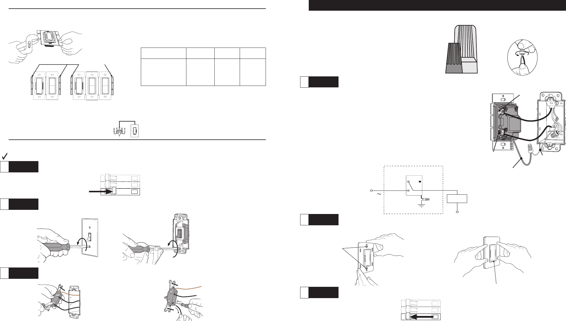
Step 1 Turn power OFF at circuit breaker or remove fuse.
Step 2 Remove wallplate. Pull switch from wall.
Step 3 Disconnect wires.
Terminal Screws:
Turn screw to loosen.
Backwired:
Insert screwdriver.
Pull out wire.
ON
OFF
ON
OFF
ON
OFF
Breaking Side
Sections
OR
No sides 1 side 2 sides
Model Number removed removed removed
RA-6D, 600 W/VA 500 W/VA 400 W/VA
RB-6D
RA-10D, 1000 W/VA 800 W/VA 650 W/VA
RB-10D
When removing side sections for multigang installations,
reduction of the dimmer’s load capacity is required. See
table below.
Do Not Remove
Outside Sections
Each Control Has
Inside Section
Removed
Middle Control Has
Two Side Sections
Removed
Step 4 Wire the
Dimmer.
Using the screws (or push-in terminals) on the
Dimmer
and the wire
connector provided:
• Connect the
Dimmer
green
ground wire to the green or bare copper
ground wire in the wallbox. If there is no ground wire in the wallbox,
consult an electrician.
• Connect the
Dimmer
black screw (or push-in terminal) to either of the
wires removed from the switch.
• Connect the
Dimmer
brass screw (or push-in terminal) to the remaining
wire removed from the switch.
• The
Dimmer
blue screw and push-in terminal are not needed for a
Single Location Installation.
ON
OFF
ON
OFF
ON
OFF
Step 5 Mount and align dimmer. Attach Claro® or Satin ColorsTM wallplate (purchased separately).
Step 6 Turn power ON.
Tighten screws
until snug.
Ensure FASSTM
switch is fully pushed in.
Align dimmer.
Attach wallplate.
Ground
Green
120 V
60 Hz
Blue
Screw
Dimmer
Hot
Neutral
Light
Fixture(s)
Brass
Screw
Black
Screw
Wiring Diagram Green wire
Important Wiring Information
Important Wiring Information
Twist wire connector tight.
Be sure no bare wire is
exposed.
When making wire connections, follow the recommended strip lengths and combinations for the supplied
wire connectors. Note: Wire connectors provided are suitable for
copper wire only.
For aluminum wire,
consult an electrician.
Small Large
Small:
Strip insulation 3/8" for 14 AWG wire
Strip insulation 1/2" for 16 or 18 AWG wire
Use to join one 14 AWG supply wire with one 16 or 18 AWG control wire.
Large:
Strip insulation 1/2" for 10, 12 or 14 AWG wire
Strip insulation 5/8" for 16 or 18 AWG wire
Use to join one or two 12 or 14 AWG supply wires with one 10, 12, 14, 16,
or 18 AWG control wire.
32
Ground wire
(bare copper or
green)
Dimmer
Black screw
Brass screw
When making wire connections, follow the recommended strip lengths and combinations for the supplied
wire connectors. Note: Wire connectors provided are suitable for
copper wire only.
For aluminum wire,
consult an electrician.
Terminal screws:
Turn screw to
loosen.
Backwired:
Insert screwdriver.
Pull out wire.
Different-colored screw (Common)
Ground
(Bare copper
or green wire)
Tag
ON
OFF
ON
OFF
ON
OFF
Replacing two 3-way switches or an
existing dimmer and a 3-way switch.
OR
Important Wiring Information
Twist wire connector tight.
Be sure no bare wire is exposed.
Small Large
Small:
Strip insulation 3/8" for 14 AWG wire
Strip insulation 1/2" for 16 or 18 AWG wire
Use to join one 14 AWG supply wire with one 16 or 18 AWG control wire.
Large:
Strip insulation 1/2" for 10, 12 or 14 AWG wire
Strip insulation 5/8" for 16 or 18 AWG wire
Use to join one or two 12 or 14 AWG supply wires with one 10, 12, 14, 16,
or 18 AWG control wire.
Two-Location
Installation
For installations involving more than one dimmer in a wallbox, refer to Multigang Installations on page 2
before beginning.
Check off Steps as completed.
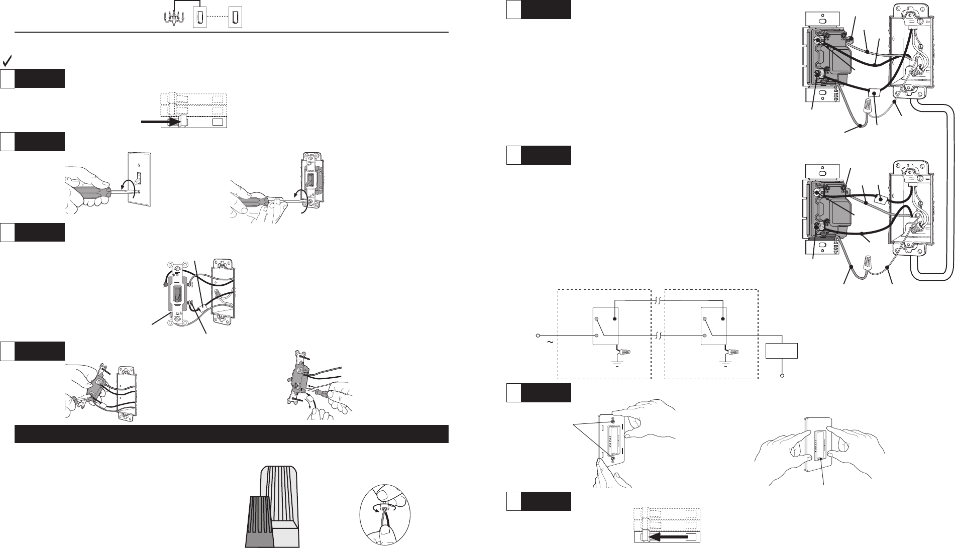
Step 1 Turn power OFF at circuit breaker or remove fuse.
Step 2 Remove wallplates. Pull switches from wall.
Step 3 At each switch location, tag the wire that is connected to the different colored screw or
screw labeled COMMON (not the green ground screw).
Step 4 Disconnect wires.
Step 7 Mount and align dimmers. Attach Claro® or Satin ColorsTM wallplates (purchased separately).
Step 8 Turn power ON.
Using the screws (or push-in terminals) on the
Dimmer
and the wire
connector provided:
• Connect
the
Dimmer
green ground wire to the green or bare copper
ground wire in the wallbox. If there is no ground wire in the wallbox,
consult an electrician.
• Connect the
Dimmer
black screw (or push-in terminal) to the tagged
wire removed from the switch.
• Select one of the remaining wires and connect it to the brass screw (or
push-in terminal) on the
Dimmer
.
• Connect the remaining wire (note its color) to the blue screw (or push-
in terminal) on the
Dimmer
.
Step 6 Wiring the
Accessory Dimmer.
• Connect the
Accessory Dimmer
green ground wire to the green or
bare copper ground wire in the wallbox.
• Connect the
Accessory Dimmer
brass screw (or push-in terminal) to
the tagged wire.
• Connect the
Accessory Dimmer
blue screw (or push-in terminal) to the
same color insulated wire connected to the
Dimmer
blue screw (or
push-in terminal) noted in Step 5.
• Connect the
Accessory Dimmer
black screw (or push-in terminal) to the
remaining wire.
ON
OFF
ON
OFF
ON
OFF
Black
Tag
Green wire
Black
Tag
Red
Ground wire
(Bare copper
or green)
Ground wire (Bare
copper or green)
Tighten screws
until snug.
Align dimmers.
Ensure FASSTM switches
are fully pushed in.
Wiring Diagram
Attach wallplates.
Step 5 Wire the
Dimmer.
Green wire
Red
Ground
Green
Ground
Green
120 V
60 Hz
Blue
Screw
Dimmer
Hot
Accessory Dimmer
Neutral
Blue
Screw
Light
Fixture(s)
Brass
Screw Brass
Screw
Black
Screw Black
Screw
54
Dimmer
Accessory
Dimmer
Blue
screw
Blue
screw
Brass
screw
Black
screw
Black
screw
Brass
screw
Terminal Screws:
Turn screw to
loosen.
Backwired:
Insert screwdriver.
Pull out wire.
ON
OFF
ON
OFF
ON
OFF
• TAG the insulated wire connected to the different
colored screw or screw labeled 'COMMON'. • TAG the two same color insulated wires which are
connected to opposite colored screws.
4-Way
Four screw connections plus a
green ground screw.
3-Way
Three screw connections plus a
green ground screw.
Note: Screw placement
may be different on
your switch.
Same colored screws
(or marked IN or OUT)
Tag
Different-colored
screw (Common) Ground (Bare copper
or green wire)
Tag
Replacing two 3-way
switches and a 4-way switch.
OR
COMPLETE
THIS STEP
BEFORE
REMOVING WIRES
FROM SWITCH.
Step 4 Disconnect wires.
Important Wiring Information
Twist wire connector tight.
Be sure no bare wire is exposed.
When making wire connections, follow the recommended strip lengths and combinations for the supplied
wire connectors. Note: Wire connectors provided are suitable for
copper wire only.
For aluminum wire,
consult an electrician.
Small Large
Small:
Strip insulation 3/8" for 14 AWG wire
Strip insulation 1/2" for 16 or 18 AWG wire
Use to join one 14 AWG supply wire with one 16 or 18 AWG control wire.
Large:
Strip insulation 1/2" for 10, 12 or 14 AWG wire
Strip insulation 5/8" for 16 or 18 AWG wire
Use to join one or two 12 or 14 AWG supply wires with one 10, 12, 14, 16,
or 18 AWG control wire.
Ground (Bare copper
or green wire)
Three-Location
Installation
For installations involving more than one dimmer in a wallbox, refer to Multigang Installations on page 2
before beginning.
Check off Steps as completed.
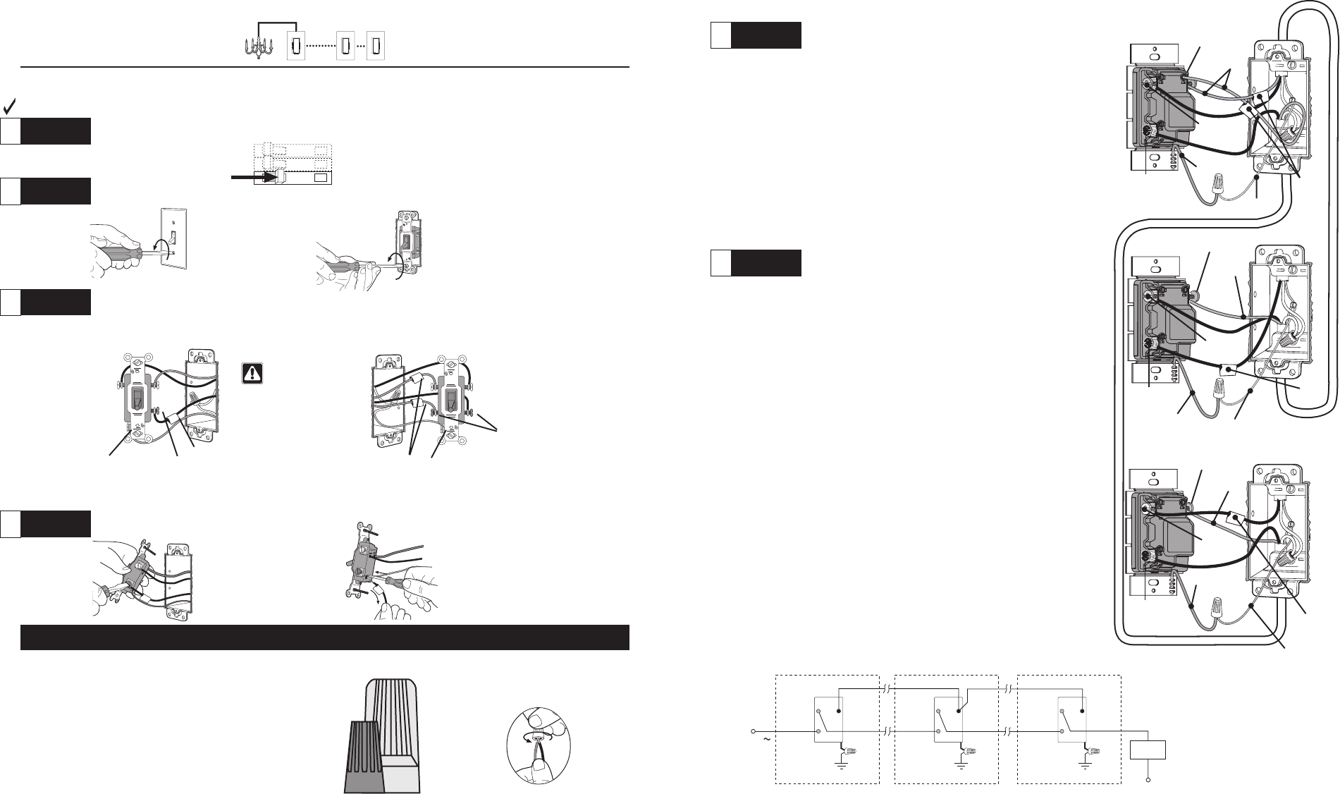
Step 1 Turn power OFF at circuit breaker or remove fuse.
Step 2 Remove wallplates. Pull switches from wall.
Step 3 Identify the switches.
Step 5 Replace the 4-way switch with an
Accessory
Dimmer.
Step 6 Replace the two 3-way switches.
Ground
Green
Ground
Green
Ground
Green
120 V
60 Hz
Blue
Screw
Dimmer
Hot
Accessory Dimmer Accessory Dimmer
Neutral
Blue
Screw Blue
Screw
Light
Fixture(s)
Brass
Screw Brass
Screw Brass
Screw
Black
Screw Black
Screw Black
Screw
Wiring Diagram
Red
wires
Tag
Red
Tag
Ground wire
(Bare copper or green)
Ground wire
(Bare copper or green)
Continued on next page
One 3-way switch MUST be replaced with a
Dimmer
and the
other with an
Accessory Dimmer.
Wiring the
Dimmer:
• Connect the
Dimmer
green ground wire to the green or bare
copper ground wire in the wallbox.
• Connect the Dimmer black screw (or push-in terminals) to the
tagged wire removed from the switch.
• Connect the
Dimmer
blue screw (or push-in terminal) to the
same color insulated wire as the
Accessory Dimmer
blue
screw (or push-in terminal) noted in Step 5.
• Connect the
Dimmer
brass screw (or push-in terminal) to the
remaining wire.
Wiring the
Accessory Dimmer:
• Connect the
Accessory Dimmer
green ground wire to the
green or bare copper ground wire in the wallbox.
• Connect the
Accessory Dimmer
brass screw (or push-in
terminal) to the tagged wire.
• Connect the
Accessory Dimmer
blue screw (or push-in
terminal) to the same color insulated wire as the
Accessory
Dimmer
blue screw (or push-in terminal) noted in Step 5.
• Connect the
Dimmer
black screw (or push-in terminal) to the
remaining wire.
Using the screws (or push-in terminals) on the
Accessory
Dimmer
and the wire connector provided:
• Connect the
Accessory Dimmer
green ground wire to the
green or bare copper ground wire in the wallbox. If there is
no ground wire in the wallbox, consult an electrician.
• Connect the
Accessory Dimmer
blue screw (or push-in
terminal) to both of the tagged wires (noting their color)
removed from the 4-way switch.
• Select one of the remaining wires and connect it to the
Accessory Dimmer
black screw (or push-in terminal).
• Connect the remaining wire to the
Accessory Dimmer
brass
screw.
Green wire
Red
wire
Green wire
Green wire
76
Accessory
Dimmer
Brass
screw
Ground
wire (Bare copper or green)
Dimmer
Accessory
Dimmer
Tags
Blue
screw
Blue
screw
Black
screw
Brass
screw
Black
screw
Brass
screw
Blue
screw
Black
screw