Lutron Electronics 0054 600W Electronic dimmer with RF communication User Manual
Lutron Electronics Company Inc 600W Electronic dimmer with RF communication
User Manual
Load Specifications
Control Load Type Min.
Load
Max.
Load
SZ-6D1
Incandescent 50 W 600 W
MLV250 W / VA 450 W /
600 VA
SZ-6ND1
Incandescent 10 W 600 W
MLV210 W / VA 450 W /
600 VA
SZ-6ANS3
Lighting 10 W / VA 6 A
Motor 0.083 A 3 A
Notes
1 Dimmer Load Type: SZ-6D and
SZ-6ND are designed for use with
permanently installed incandescent,
magnetic low-voltage (MLV), or
tungsten halogen only. Do not
install dimmers to control standard
receptacles or motor-operated
appliances.
2 Low-Voltage Applications: Use
SZ-6D and SZ-6ND with magnetic
(core and coil) low-voltage
transformers only. Not for use with
electronic (solid-state) low-voltage
transformers.
Operation of a low-voltage circuit
with lamps inoperative or removed
may result in transformer overheating
and premature failure. Lutron strongly
recommends the following:
• Do not operate low-voltage circuits
without operative lamps in place.
• Replace burned-out lamps as quickly
as possible.
• Use transformers that incorporate
thermal protection or fused
transformer primary windings to
prevent transformer failure due to
overcurrent.
3 Switch Load Type: SZ-6ANS is
designed for use with all permanently
installed lighting loads and with motor
loads up to 1/4 HP (5.8 A).
Install in accordance with all local and
national electrical codes.
Caution! These controls
must not be used to control
equipment that is not visible
from every control location.
They must also not be used to control
equipment that could create hazardous
situations such as entrapment if
operated accidentally. Examples of such
equipment which must not be operated
by these controls include (but are not
limited to) industrial doors, microwave
ovens, heating pads, etc. It is the
installer’s responsibility to ensure that
the equipment being controlled is visible
from every control location and that
only suitable equipment is connected to
these controls.
Environment: Ambient operating
temperature: 32 to 104 °F (0 to 40 °C),
0 to 90% humidity, non-condensing.
Indoor use only.
Spacing: If mounting one control above
another, leave at least 4½ in. (114 mm)
vertical space between them.
Faceplates: Use Lutron Stanza
faceplates for best color match and
aesthetic appearance. Do not paint
controls or faceplates.
Cleaning: To clean, wipe with a clean
damp cloth. DO NOT use any chemical
cleaning solutions.
Wallboxes: Lutron recommends using
3½ in. (89 mm) deep wallboxes for
easier installation. Several controls may
be installed in one multigang wallbox
— see Derating Chart.
RF Device Placement: RF dimmers
and switches must be located within
20 feet (6 m) of an RF signal repeater or
a device configured as a repeater.
Stanza RF dimmers or switches cannot
be controlled by the system until they
are addressed and programmed. They
will work as stand-alone controls only.
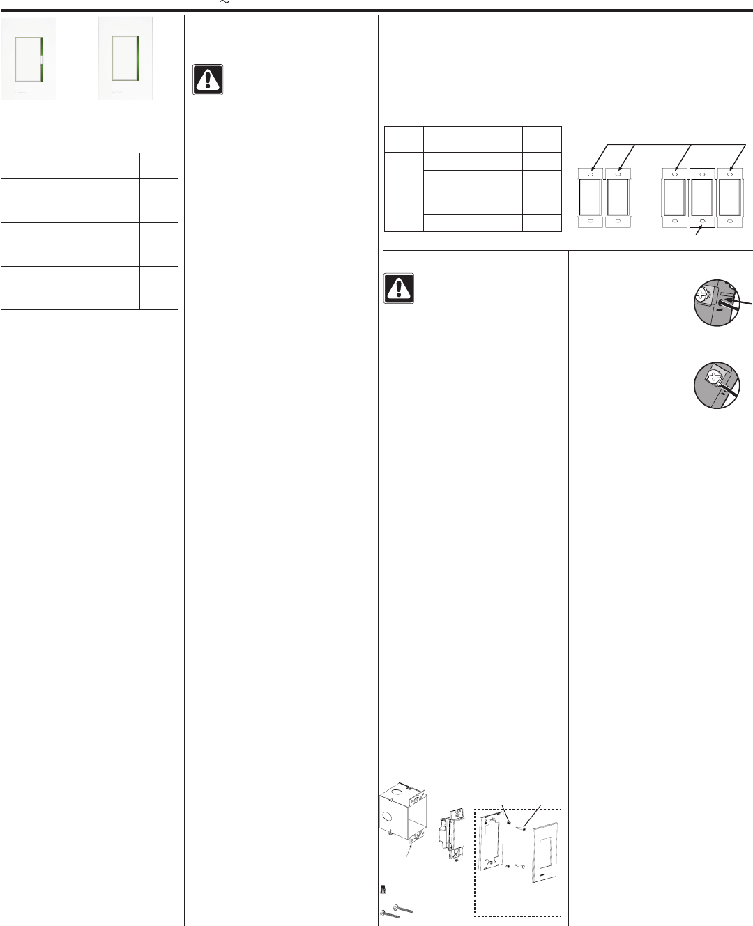
In multigang installations, several
controls are grouped horizontally in one
multigang wallbox.
When combining controls in a wallbox,
derating is required.
Derating Chart
Control Load Type End of
Gang
Middle
of Gang
SZ-6D,
SZ-6ND
Incandescent 500 W 400 W
MLV 400 W /
500 VA
300 W /
400 VA
SZ-
8ANS
Lighting 5 A 3.5 A
Motor 3 A 3 A
Installation
Caution! Locate and remove
fuse or lock circuit breaker in the
OFF position before proceeding.
Wiring with power ON may result
in personal injury or death.
Short Circuit Check: Check the
installation for short circuits before
installing control(s). With power OFF,
install standard mechanical switch(es)
between hot and load. Restore power.
If lights do not work or a breaker trips,
correct wiring and check again. Install
control(s) only when short is no longer
present. Warranty is void if control is
turned ON with a shorted circuit.
1. Turn power OFF at fusebox or circuit
breaker.
2. Prepare wires. When making
wire connections, follow the
recommended strip lengths and
combinations for the supplied wire
connector.
Note: Wire connectors provided are
suitable for copper wire only.
Wire Connector:
• Strip insulation 3/8 in.
(9.5 mm) for #14 AWG
(1.5 mm2) wire
• Strip insulation 1/2 in.
(12.7 mm) for #16 or 18 AWG (1.0 mm2
or 0.75 mm2) wire
• Use to join one #14 AWG
(1.5 mm2) or #12 AWG
(2.5 mm2) ground wire with one #18
AWG (0.75 mm2)
control ground wire.
Twist wire connector tight. Trim or strip
wallbox wires to the length indicated
by the strip gauge on the back of the
control.
Push-In Terminals:
Insert wires fully. Push-in
terminals are for use with
#14 AWG (1.5 mm2) solid
copper wire only. DO NOT
use stranded or twisted
wire.
OR
Screw Terminals: Tighten
securely to 5 in-lbs (0.55
N•m). Screw terminals are
for use with solid copper
wire only. DO NOT use
stranded or twisted wire.
3. Wire controls as follows:
Single location installation: See
Wiring Diagrams 1 and 2.
Power Booster and Interfaces:
When using power boosters or
interfaces, see wiring diagrams
provided with the interface.
4. Push all wires back into the wallbox
and loosely fasten the control to the
wallbox using the control mounting
screws provided. Do not pinch the
wires.
5. Attach Lutron Stanza faceplate
adapter and faceplate.
a. Install faceplate adapter onto front
of control(s).
b. Tighten control mounting screws
until faceplate adapter is flush to
wall (do not over-tighten).
c. Snap faceplate onto faceplate
adapter, and verify that control is
aligned properly.
d. If control(s) is (are) misaligned,
loosen mounting screws
appropriately.
6. Restore power. Check for correct
local operation (see Dimmer
Operation and Switch Operation).
Installation Instructions
Please Read Before Installing
StanzaTM StanzaTM Dimmers
SZ-6D, SZ-6ND
StanzaTM Switch
SZ-6ANS
120 V 50 / 60 Hz
Important Notes Multigang Installations
Dimmer and
Dimmer with Neutral Switch
Middle of gang
End of gang
Control Location for Ganging
Mounting Diagram
Control
mounting
screws
Wallbox Control
Included:
Wire Connector (1)
Mounting Screws (2)
Faceplate
adapter
mounting
screws
Faceplate/adapter purchased
separately.
FCC Information
Note: This equipment has been tested and found to comply with
the limits for a Class B digital device pursuant to Part 15 of the
FCC rules. Operation is subject to the following: (1) This device
may not cause harmul interference, and (2) this device must
accept any interference received, incouding interference that
may cause undesired operation.
Lutron Electronics Co., Inc.
Made and printed in the U.S.A.
P/N 030-994 Rev. A 6 /08
Technical support: USA, Canada, Caribbean: 1.800.523.9466
Mexico: +1.888.235.2910
Central/South America: +1.610.282.6701
Warranty: 1-year limited warranty standard. 2-year parts and labor warranty, with
8-year pro-rated parts replacement on commissioned systems.
These products may be covered under one or more of the following U.S. patents: 5,248,919;
5,637,930; 5,838,226; 5,848,054; 5,905,442; 6,687,487; 6,803,728; and corresponding foreign
patents. U.S. and foreign patents pending. Lutron and the sunburst logo are registered
trademarks and FASS and Stanza are trademarks of Lutron Electronics Co., Inc.
© 2008 Lutron Electronics Co., Inc.
R
Dimming Slider
Slide up to brighten; slide down to dim
Load must be on for slider to affect intensity
Dimmer Operation (SZ-6D, SZ-6ND)
Switch Operation (SZ-6ANS)
Indicator light in slider track
Glows softly for easy locating of control
Track ends flash amber to indicate programming/
addressing mode
Tapswitch
Turns load on to slider level and off
FASSTM
Front-accessible service switch (facilitates safe bulb
replacement)
Pull down to remove all electrical power from load
and deactivate dimmer
Push up to restore power to load and dimmer
Indicator light in slider track
Glows softly for easy locating of control
Tapswitch
Turns load on and off
FASSTM
Front-accessible service switch (facilitates safe bulb
replacement)
Pull down to remove all electrical power from load
and deactivate switch
Push up to restore power to load and switch
Lamp Replacement
Caution! For any procedure other than routine lamp replacement, power
must be disconnected at the main electrical panel. Working with power
ON may result in personal injury or death.
For routine lamp replacement, remove power from the fixture(s) by pulling down
the FASS switch on the Dimmer / Switch.
Troubleshooting Guide
Symptom Cause and Action
Load is off and there
is no indicator on the
dimmer/switch
Power not present
• Circuit breaker OFF or tripped. Perform short circuit check.
• FASS is in the OFF position. Move FASS to the ON position by
fully pushing it up.
Wiring error
• Check wiring to be sure it agrees with installation instructions
and wiring diagrams.
Lamps burned out or not installed
• Replace or install lamps.
Dioded lamps
• Replace with non-dioded lamps.
Damaged dimmer/switch
• Device may have been damaged by previous overload or
miswire. Replace device.
Dimmer / switch indica-
tor is on but load can-
not be turned on and/or
cannot be turned off
Wiring error
• Check wiring to be sure it agrees with installation instructions
and wiring diagrams.
Damaged dimmer/switch
• Device may have been damaged by previous overload or
miswire. Replace device.
Light turns ON and OFF
continuously
Load is less than minimum load requirement
• Make sure the connected load meets the minimum load
requirement for that control. See Load Specifications table.
Improper load type
• Check that the load being dimmed is not non-dimmable. See
Load Specifications table.
Lights don’t switch ON/
OFF from keypad
Improper programming
• Check programming in the Stanza software.
Out of RF range
• Ensure device is within 20 feet (6 m) of another device
configured as a repeater.
Wiring
• Wiring error. Check wiring to be sure it agrees with installa-
tion instructions and wiring diagrams.
Faceplate is warm Solid-state control dissipation
• Solid-state dimmers and switches internally dissipate about
2% of the total connected load. It is normal for dimmers and
switches to feel warm to the touch during operation.
Control is buzzing or
humming
It is normal for dimmers and switches to emit a slight buzzing or
humming sound.
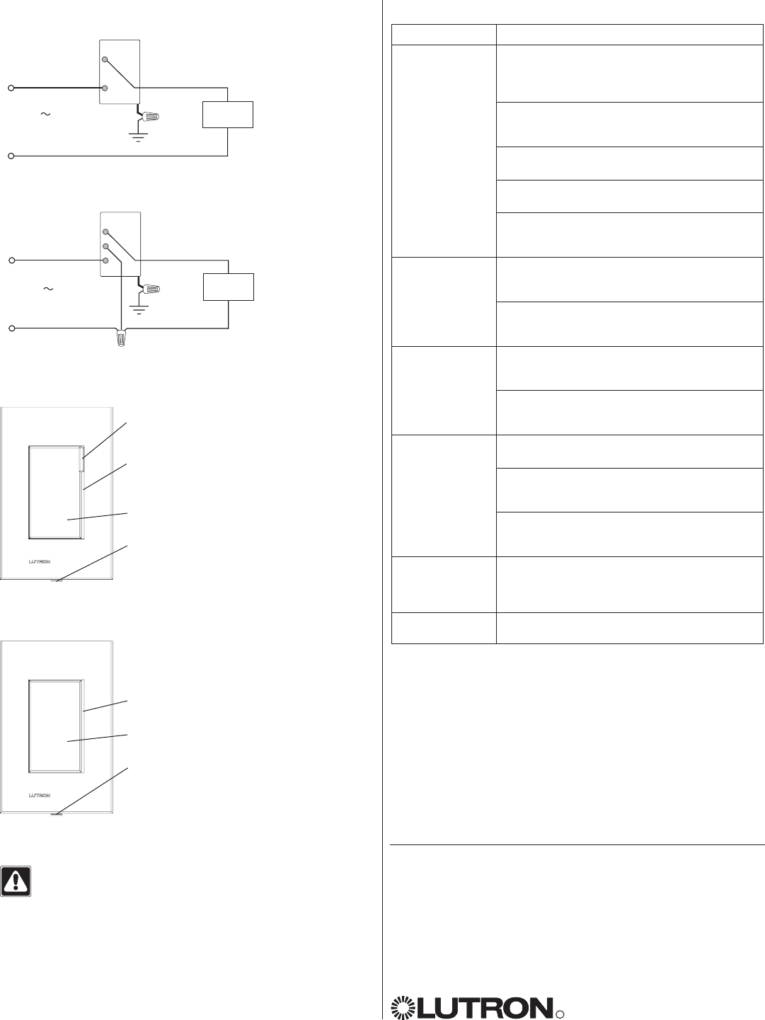
Single Location Installation
SZ-6D
Wiring Diagram 1
Dimmer/Switch
Brass
Black
Lighting
load
Hot/Live
Neutral
Green
Ground
120 V
50 / 60 Hz
Single Location Installation with Neutral
SZ-6ND, SZ-6ANS
Wiring Diagram 2
Dimmer/Switch
Brass
Black
Load
Hot/Live
Neutral
Green
Ground
120 V
50 / 60 Hz
Silver
Returning the Dimmer/Switch to
Factory Settings
1. Triple-tap the tapswitch quickly (within
1 second).
2. Press and hold the tapswitch for 5
seconds (until the load ashes) .
3. Triple-tap the tapswitch quickly again.
Notes
• Returning to factory settings will clear
all programming from the dimmer/
switch, and will prevent it from being
controlled over RF from a keypad or
control interface.
• After being returned to factory defaults,
the device will need to be re-addressed
as part of a system.