Lutron Electronics 0059 Remote Control Transmitter User Manual
Lutron Electronics Company Inc Remote Control Transmitter
User Manual
LCJ Sensor Installation
Revision History
15th July, 2008 Jason Pamphilis
• Updates based on Alpha 1.0 feedback
9th July, 2008 Brian Valenta
• Added revision history
• Updates based on 07.08.2008 review (see meeting minutes) – not complete
07.03.2008 Brian Valenta
• First draft
1 of 7
Important Notes
1. Use only high quality lithium batteries, size CR123, 3V. Do not use rechargeable
batteries. Using improperly rated batteries could damage the sensor.
2. Clean control with a soft damp cloth only. Do not use any chemical cleaners.
3. The sensor is intended for indoor use only. Operate in ambient temperatures between
0 °C (32 °F) and 40 °C (104 °F) and 0-99% relative humidity condensing.
4. Do not paint controls.
5. The range and performance of the RF System is highly dependent on a variety of
complex factors such as:
• Distance between system components
• Geometry of the home
• Construction of walls separating system components
• Electrical equipment located near system components
6. The range and performance of the Motion Sensor is highly dependent on line of sight.
The occupant sensor must have an unobstructed view of the room. Do not mount
behind or near tall cabinets, shelves, hanging fixtures, etc.
FCC Information
NOTE: This equipment has been tested and found to comply with the limits for a Class B
digital device, pursuant to part 15 of the FCC rules. These limits are designed to provide
reasonable protection against harmful interference in a residential installation. This
equipment generates, uses and can radiate radio frequency energy and, if not installed and
used in accordance with the instructions, may cause harmful interference to radio or
television reception, which can be determined by turning the equipment off and on, the
user is encouraged to try to correct the interference by one or more of the following
measures:
• Reorient or relocate the receiving antenna.
• Increase the separation between the equipment and receiver.
• Connect the equipment into an outlet on a circuit different from that to which the
receiver is connected.
• Consult the dealer or an experienced radio/TV technician for help.
Caution: Changes or modifications not expressly approved by Lutron Electronics Co.
could void the user’s authority to operate this equipment.
Operation is subject to the following: (1) This device may not cause harmful interference,
and (2) this device must accept any interference received, including interference that may
cause undesired operation.
Included Parts
1. One Sensor
2. Two Batteries
3. One Mounting Bracket
4. Two screws
5. Two Anchors
6. Temporary Mounting Material (putty or sticky tape)
7. Installation Sheet
2 of 7
Overview
Pre-Installation (Required)
Pre-Installation section covers energizing the sensor.
System Setup (Required)
System Setup section covers the steps to associate a sensor with a receiver.
Sensor Placement
Sensor Placement covers the rules for proper sensor placement.
Motion Sensor Coverage Testing
Motion Sensor Coverage Setup covers the steps to test the motion sense coverage area.
Permanent Installation (Required)
Permanent Installation covers the steps to securely mount the sensor.
Pre-Installation (Note: Not Applicable to Alpha 1)
IMPORTANT: Please read and perform these steps in order.
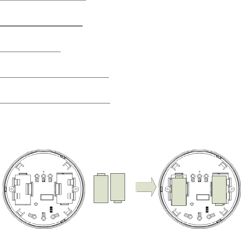
1. Install the batteries.
Add Remove
Test
Ambient Sensitivity Timeout
High
Medium
Low
30 minutes
15 minutes
5 minutes
Add Remove
Test
Ambient Sensitivity Timeout
High
Medium
Low
30 minutes
15 minutes
5 minutes
Conditional
Install wall dimmer, Refer to MRF-600M-WH data sheet.
3 of 7
System Setup
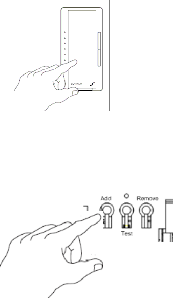
1. Turn on the Dimmer.
2. Remove mounting plate. Have sensor in hand.
3. Press and hold the Dimmer’s tap button during this entire step. The LEDs blink one at
a time, from the bottom up to the top. After approximately 8 seconds, the LEDs will
start to cycle slowly from top to bottom (setup mode). Continue to hold the tap button
and go to step 4.
4. While observing the dimmer, press and hold the Sensor Add button until the
dimmer’s LEDs chase from top to bottom. As the Dimmer learns the Sensor, the
LEDs on the Dimmer will cycle quickly from top to bottom. Release the Dimmer tap
button to exit set-up mode, and then release the Sensor Add button.
Sensor Placement
1. Find a suitable location to mount the sensor, taking into account the Sensor RF
Coverage area and the Motion Floor Coverage area. Sensors must be within 30 feet of
the receiving RF devices. Motion Floor Coverage is line of sight.
4 of 7
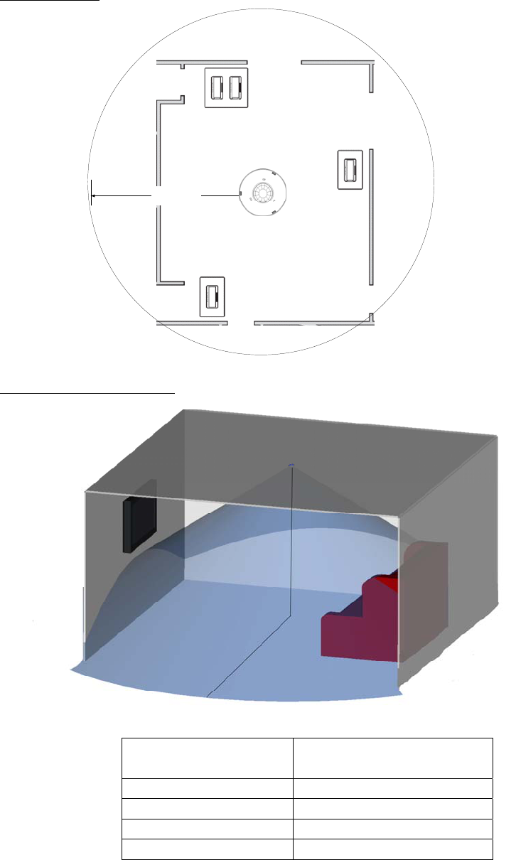
RF Coverage
30 feet
Motion Floor Coverage
Ceiling
Height
Motion Floor
Coverage
Radius
*Motion Floor Coverage indicates the area in which the LCJ sensor is capable of detecting motion.
Ceiling Height (feet) Motion Floor Coverage
Radius (feet)
8 12
9 13.5
10 15
12 18
5 of 7
Motion Sensor Coverage Testing
1. Remove sensor from wall-mounting bracket.
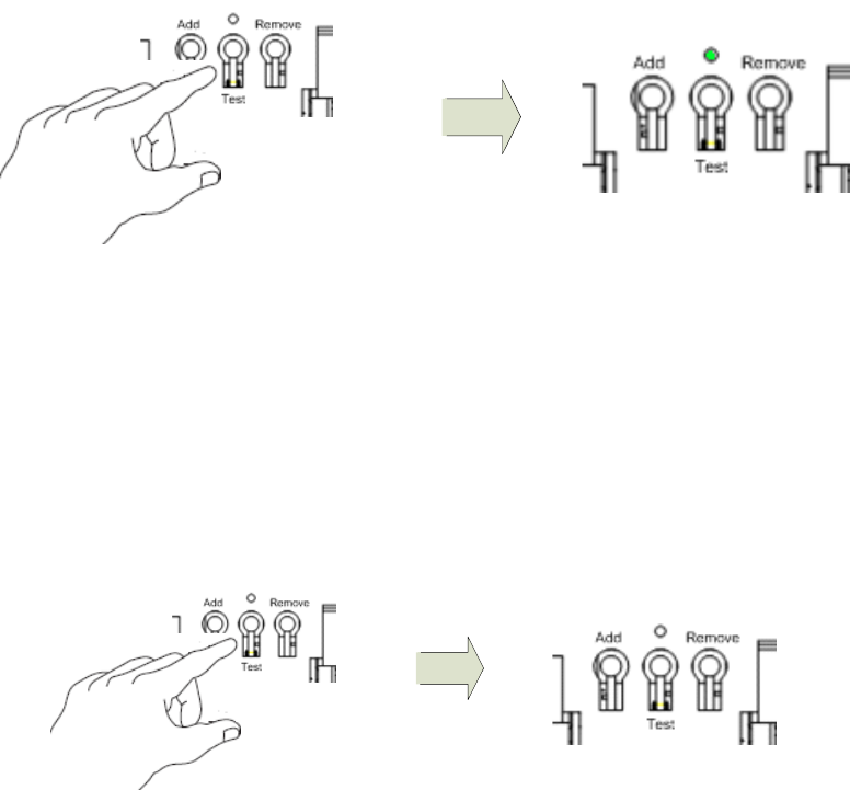
2. Press test mode.
3. Replace wall-mounting bracket.
4. Adhere unit to ceiling.
5. Confirm the coverage area by walking in the Sensor space and observe the Lens LED
state. The Lens LED in the on state signifies motion detected and the Lens LED in the
off state signifies motion not detected.
6. Tweak the sensor coverage area by temporarily mounting in a different location if
necessary and repeat this step as necessary.
7. Remove the sensor from Test Sensitivity Mode by pressing the Test button. Test LED
will turn off. Note: Test Sensitivity Mode automatically exits 5 minutes after entering
the mode.
8. Remove and discard “Temporary Mounting Material”.
6 of 7
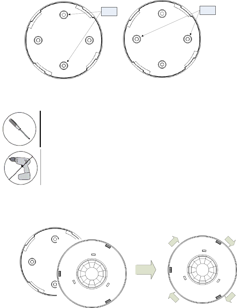
Permanent Installation
1. Note: Anchor usage is optional. Skip to the next step if not using anchors.
1.1. Drill two 3/16-inch holes for the provided anchors using the mounting bracket as
a template. The anchor holes should be across from each other.
Anchor
Locations
Anchor
Locations
1.2. Install anchors.
2. Place mounting bracket flush against the wall with the smooth side against the wall
and install the two provided screws using a hand screwdriver.
NOTICE: Use of a hand screwdriver is recommended.
NOTICE: Use of a power screwdriver is NOT recommended
3. Attach the Sensor to the mounting bracket by twisting in a clockwise direction until
the Sensor and mounting bracket are attached.
7 of 7