Lutron Electronics 0068 RF Daylight Sensor User Manual Uesr Manual
Lutron Electronics Company Inc RF Daylight Sensor Uesr Manual
Uesr Manual
1
2
3
4
5
6
To remove the bracket from the ceiling, grasp the removal tab on the adhesive strip
and pull the tab VERY SLOWLY straight across the ceiling, stretching the strip until
the bracket releases from the ceiling. Discard the strip. NEVER pull the strip at an
angle, as it may break or damage the ceiling surface.
Identify a location for the Sensor (see section C. Sensor Placement).
Remove the black “wall side” liner from the adhesive strip.
Position the mounting bracket on the ceiling and press
firmly for several seconds.
Attach the Sensor to the mounting bracket.
Perform the Calibration and Test the Sensor as described in section E. Calibration
and F. Testing the Daylight Sensor.
If the Sensor does not perform satisfactorily from this location, it may be moved to
another location by pulling the Sensor straight down and repeating steps 2.1 – 2.7.
If the Sensor’s performance is satisfactory, it should be permanently attached to the
ceiling tile, as described in section H. Permanent Mounting Methods.
Testing the Daylight Sensor
Before testing, ensure power to the lighting circuit is ON and the lighting control
system is setup and calibrated properly.
The lighting circuit should be energized only when all wiring is complete and all
persons are clear of fixtures/devices. Turn power ON only after checking that it is
safe to do so.
Activate Test mode by pressing the “Test” button on the
front of the Sensor. The lens will flash indicating that the
mode was entered.
Select all Dimmers or Electronic Switches that you
want to test by pressing the tap button.
Cover the Sensor – the system should increase/switch on the lights in the room
Shine light on the Sensor – the system should decrease/switch off
the lights in the room
With the lights on, do nothing to the Sensor – If the lights in the room cycle on and
off, there is too much feedback from the lights – consider moving Sensor away
from lights or re-calibrate the system (see section E. Calibration).
Exit Test mode by pressing the “Test” button again.
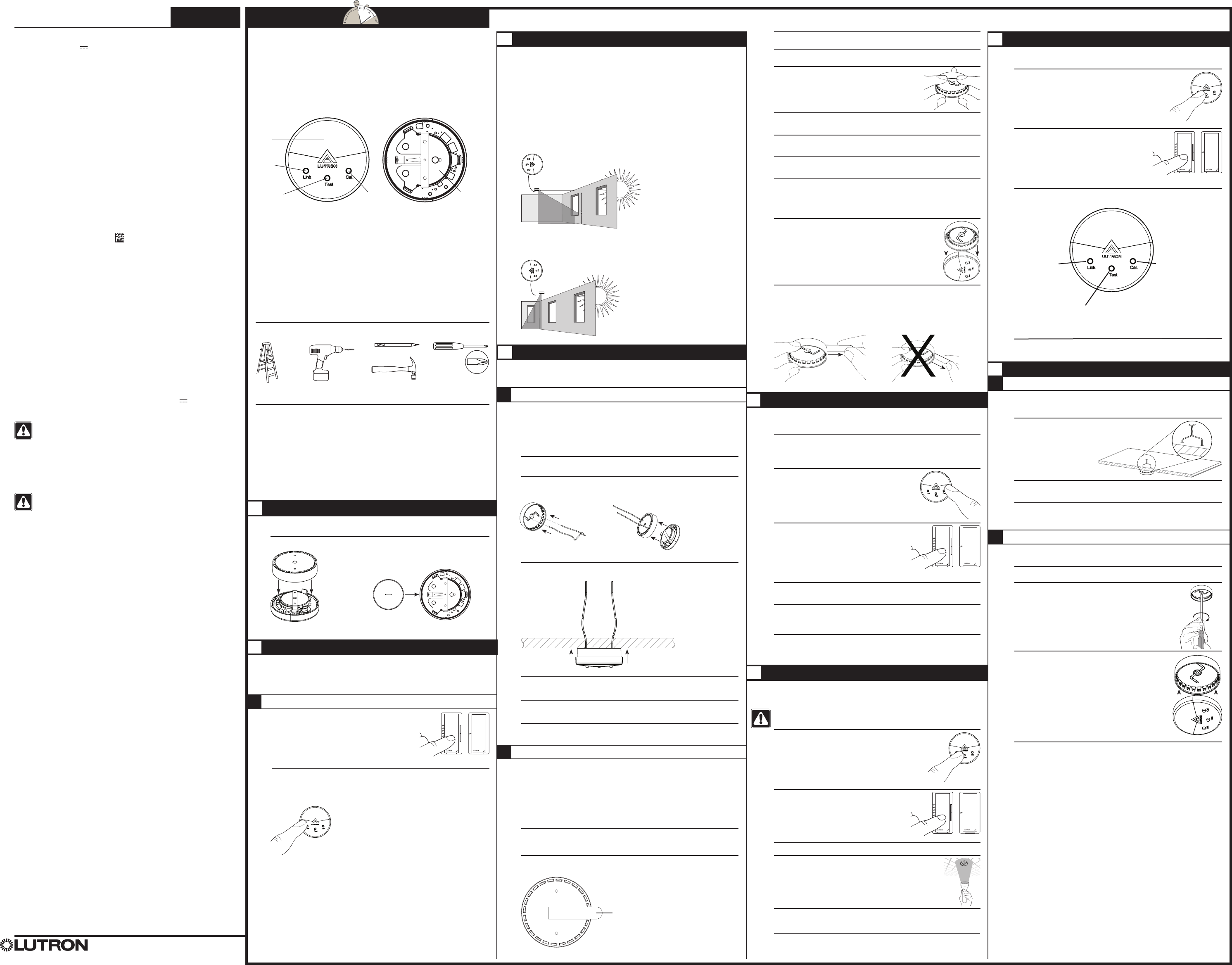
Sensor Placement
Determine the Daylight Sensor Mounting Location using the diagrams below:
• The arrow on the daylight sensor points toward the area viewed by the sensor.
• Place the daylight sensor so its viewing area is centered on the nearest window at a
distance from the window of one and two times the effective window height (H).
• The effective window height (H) starts at the window sill or 3 ft (1 m) up from the
floor, whichever is higher, and ends at the top of the window.
• Ensure that the view of the daylight sensor is not obstructed.
• Do not position the daylight sensor in the well of a skylight or above indirect lighting
fixtures.
• For narrow areas where the daylight sensor cannot be placed 1-2 (H) from windows,
place sensor near windows facing into the space.
Temporary Mounting Methods
If you are uncertain about correctly positioning the Sensor, the following temporary
mounting and testing procedures are recommended to verify proper performance
before permanently installing the Sensor.
Temporary Drop Ceiling Mounting
Use this procedure if the Sensor will be mounted on a ceiling tile.
The ceiling tile mounting wire is provided for both temporary and permanent mounting
of the Sensor to drop ceilings composed of multiple tiles. It is designed to allow
temporary mounting, testing, and repositioning (if necessary) of the Sensor without
damaging a ceiling tile. Once the Sensor’s final position has been chosen, the
mounting wire can be twisted to lock the Sensor in place permanently.
Remove the mounting bracket from the base of the Sensor.
Insert the ceiling tile mounting wire through the two smaller
holes in the mounting bracket and replace the mounting bracket.
Mount Sensor to a ceiling tile by inserting the wire legs through the tile making sure the
Sensor is flush to the tile.
Perform the Calibration and Test the Sensor as described in sections E. Calibration
and F. Testing the Daylight Sensor.
If the Sensor does not perform satisfactorily from this location, it may be moved to
another location by pulling the Sensor straight down and repeating steps 1.3 and 1.4.
If the Sensor’s performance is satisfactory, it should be permanently attached to the
ceiling tile, as described in section H. Permanent Mounting Methods.
A
Installation
The Sensor installation procedure is outlined below. Please follow these steps to ensure the
Sensor will perform as intended:
A. Pre-Installation F. Testing the Daylight Sensor
B. Set-Up G. Tuning the System
C. Sensor Placement and Coverage H. Permanent Mounting Methods
D. Temporary Mounting Methods
E. Calibration
Pre-Installation
Before setting up the Sensor, the corresponding dimming or switching device(s) should
be installed. Refer to that product’s installation sheet for instructions.
Pull and remove mounting bracket to insert battery with the negative (–) side up.
Set-Up
In order for the Sensor to operate properly, it must first be set up with a corresponding
dimming or switching device. The procedure for setting up a Sensor with a Maestro
Wireless® (MRF2- only) Dimmer or Electronic Switch is detailed below.
If setting up a Sensor with a different device, visit www.lutron.com/occsensors or
consult the installation guide for that device for the correct set-up procedure.
Setting up a Sensor with a Maestro Wireless Dimmer or Electronic Switch
Place the Dimmer or Electronic Switch in set-up mode
by pressing and holding the tap button for approximately
6 seconds until all LEDs on the device begin flashing.
Release the tap button.
Add the Sensor to the Dimmer or Electronic Switch by pressing and holding the “Link”
button on the front of the Sensor for approximately 6 seconds until the lens flashes briefly.
The lights in the room will also flash 3 times, indicating the Sensor has been successfully
added. The Dimmer or Electronic Switch will exit set-up mode automatically.
C
Key Features
· Easy Installation. No wiring required.
· Easy Set-Up. Default settings are ideal for most situations. Simple and intuitive
adjustments available.
· Low Maintenance. 10-year battery life. Convenient low-battery indicator.
· Daylight Dimming and Switching. Sensors integrate with various Lutron® Dimmers and
Switches.
· Ceiling-Mounted Style.
· Multiple Devices. Each Sensor may be added to up to 10 receiving devices.
Sensor Operation
Dimming – The lights must be manually turned on at the dimming device. The Sensor will
automatically decrease the electrical light as daylight increases, and vice versa.
Switching – The lights must be manually turned on at the switching device. The Sensor will
automatically turn the lights off once sufficient daylight is available in the space.
NOTE: For dimming and switching systems, the lights can also be manually turned off at
any time by using the dimming or switching device directly.
B
®
Lutron Electronics Co., Inc.
7200 Suter Road
Coopersburg, PA 18036-1299, U.S.A.
Made and printed in the U.S.A. 12/09 P/N 041-261 Rev. A
Important Notes
1. This Sensor is part of a system and cannot be used to control a load without a
compatible dimming or switching device. Refer to the instruction sheets of the receiving
devices for installation information.
2. Clean Sensor with a soft damp cloth only. DO NOT use any chemical cleaners.
3. The Sensor is intended for indoor use only. Operate between 32 °F and 104 °F
(0 °C and 40 °C).
4. DO NOT paint Sensor.
5. Use only high-quality lithium batteries, one (1) size CR2450, 3 V (ANSI-5029LC,
IEC-CR2450). DO NOT use rechargeable batteries. Using improperly rated batteries
could damage the Sensor.
CAUTION: DO NOT disassemble, crush, puncture, or incinerate the batteries.
DO NOT dispose of batteries in normal household waste. Please recycle, take
to a proper battery disposal facility, or contact your local waste disposal provider
regarding local restrictions on the disposal or recycling of batteries.
6. The range and performance of the RF system is highly dependent on a variety of
complex factors such as:
· Distance between system components
· Geometry of the building structure
· Construction of walls separating system components
· Electrical equipment located near system components
CAUTION: This product must not be used to control equipment which could
create hazardous situations, such as entrapment, if operated accidentally.
Examples of equipment which must not be controlled with this product include
(but are not limited to) motorized gates, garage doors, industrial doors, etc.
1
1.1
1.2
2
Removing Temporary Mounting Strip
Remove the Sensor from the mounting bracket by pulling downward.
3
3.1
Temporary Solid Ceiling Mounting
Use this procedure if the Sensor will be mounted on a solid, continuous ceiling surface
such as drywall, plaster, concrete, or wood.
Two 3M™ Command™ adhesive strips are provided for temporarily mounting and testing the
Sensor on smooth, solid ceiling surfaces. These strips are designed for easy, damage-free
removal and are not reusable. These strips should not be used for permanently mounting
the Sensor (see section H. Permanent Mounting Methods ). Carefully follow the removal
instructions below to ensure the ceiling is not damaged during removal.
NOTE: DO NOT use the adhesive strips on ceiling tiles, as they will likely cause damage
to the tile upon removal.
Remove the mounting bracket from the base of the Sensor.
Peel the red “Command Strips” liner off of one of the adhesive strips and apply the
strip to the flat side of the mounting bracket as shown in the diagram. Press firmly.
NOTE: Leave the removal tab exposed past
the edge of the bracket so it can be accessed
for removal later.
2.1
2.3
2.4
2.5
2.6
2.7
2.8
2.9
• Easy-to-follow
Instructions
P/N 041-261
Limited Warranty
(Valid only in U.S.A., Canada, Puerto Rico, and the Caribbean.)
Lutron will, at its option, repair or replace any unit that is defective in materials or manufacture within one year after purchase.
For warranty service, return unit to place of purchase or mail to Lutron at 7200 Suter Rd., Coopersburg, PA 18036-1299,
postage pre-paid.
This warranTy is in lieu of all oTher express warranTies, and The implied warranTy of
merchanTabiliTy is limiTed To one year from purchase. This warranTy does noT cover The cosT of
insTallaTion, removal or reinsTallaTion, or damage resulTing from misuse, abuse, or damage from
improper wiring or insTallaTion. This warranTy does noT cover incidenTal or consequenTial damages.
luTron’s liabiliTy on any claim for damages arising ouT of or in con nec Tion wiTh The manufacTure,
sale, insTallaTion, delivery, or use of The uniT shall never exceed The pur chase price of The uniT.
This warranty gives you specific legal rights, and you may have other rights which vary from state to state. Some states do
not allow the exclusion or limitation of incidental or consequential damages, or limitation on how long an implied warranty
may last, so the above limitations may not apply to you. Patents pending. Lutron, Maestro Wireless, and the Sunburst logo are
registered trademarks and Radio Powr Savr is a trademark of Lutron Electronics Co., Inc. ANSI is a registered trademark of the
American National Standards Institute. IEC is a trademark of the International Electrotechnical Commission. 3M and Command
are trademarks of 3M Company.
© 2009 Lutron Electronics Co., Inc.
Technical Assistance
For questions concerning the installation or operation of this product, call the
Lutron Technical Support Center. Please provide exact model number when calling.
U.S.A. and Canada (24 hrs / 7days)
1.800.523.9466 Fax +1.610.282.6311
Mexico 8am – 8pm ET
+1.888.235.2910
Other countries 8am – 8pm ET
+1.610.282.3800 www.lutron.com
FCC Information
NOTE: This equipment has been tested and found to comply with the limits for a Class B digital device,
pursuant to part 15 of the FCC rules. These limits are designed to provide reasonable protection against
harmful interference in a residential installation. This equipment generates, uses and can radiate radio
frequency energy and, if not installed and used in accordance with the instructions, may cause harmful
interference to radio and television reception, which can be determined by turning the equipment off and on.
The user is encouraged to try to correct the interference by one or more of the following measures:
· Reorient or relocate the receiving antenna.
· Increase the separation between the equipment and receiver.
· Connect the equipment into an outlet on a circuit different from that to which the receiver is connected.
· Consult the dealer or an experienced radio/TV technician for help.
Caution: Changes or modifications not expressly approved by Lutron Electronics Co. could void the user’s
authority to operate this equipment.
This device complies with Part 15 of the FCC rules. Operation is subject to the following two conditions:
1. This device may not cause harmful interference, and
2. This device must accept any interference received, including interference that may cause undesired operation.
NOTE: Pull very slowly. NOTE: Do not pull at an angle.
English
Radio Powr Savr™
Installation Instructions Please Read Before Installing
Wireless Battery-Powered Daylight Sensor
LRF2-DCRB-WH 3 V 20 mA 434 MHz
Compatible Products
For a full list of compatible products visit www.lutron.com/daylightsensor
Product Description
Lutron’s Daylight Sensor is a wireless, ceiling-mounted, battery-powered device that
automatically controls lights through RF communication with a dimming or switching
device. The Sensor detects light in the space, and then transmits the appropriate
commands to the associated dimming or switching device. When sufficient daylight is
available, the system will decrease or turn off the electrical light. When insufficient daylight
is available, the system will increase the electrical light.
Press to test
system
functionality
Sensor
diffuser
Press to
assign load
control
1.2
1.3
1.4
1.5
1.6
Note: Do not twist wire legs together.
Tools You May Need
Getting Started:
D
1.1
1
1
2
ECalibration
Calibration must be done when daylight is available but not extremely bright
Set Light Level
• Maestro Wireless Dimmer – Adjust each dimmer to a level in order to achieve the
desired light level
• Maestro Wireless Electronic Switch – Toggle the lights to on
Activate the Calibration procedure by pressing the “Cal”
button on the front of the Sensor for approximately
6 seconds until the lens flashes solid. The LEDs on
all associated Dimmers or Electronic Switches should
be flashing.
Select all Dimmers or Electronic Switches that you
want to calibrate by pressing the tap button.
Move out of the way of the sensor so as to not interfere with the light measurements.
Calibration automatically begins when the LED’s on all associated Dimmers or
Electronic Switches stop flashing (approximately 30 seconds after pressing the
“Cal” button). The calibration will automatically turn lights on and off (total time
approximately 3 minutes)
The calibration is complete once the lights in the room flash three times. The Sensor
and selected Dimmers or Electronic Switches automatically enter test mode once
calibration is complete.
Location for average size areas
Arrow points towards the area viewed by the sensor (toward windows)
Bottom of sensor
H = Effective Window Height
Area viewed
by sensor
H
3 ft
1-2 H
Location for narrow areas (corridors, private offices)
Arrow points towards the area viewed by the sensor (away from window)
2.2
1
2
3
4
5
F
Tuning the System
Adjust the system’s target light level. This can be used to change the entire system,
or one zone in the system
Activate Tuning mode by pressing the “Test” button on the
front of the Sensor for approximately 6 seconds until the lens
turns on solid.
Select the Dimmer or Electronic Switch that you
want to adjust by pressing the tap button.
Change the target light level by pressing the “Link” or the “Cal” button on the front of
the Sensor. Pressing the “Test” button returns the settings to the default value.
1
2
3
G
Instructions Install a Sensor in as
little as 15 minutes.
Press to
calibrate
system
Battery
compartment
Permanent Mounting Methods
Permanent Drop Ceiling Mounting
After the Sensor has been temporarily mounted, leave the Sensor in place on the
tile and either take the tile down or remove an adjacent tile to gain access to the
legs of the mounting wire on the back of the tile.
Twist the wire legs together tightly so the mounting bracket
remains snug against the tile.
Replace the tile.
If desired, repeat the wireless communication tests for verification.
Permanent Solid Ceiling Mounting
Drill one 3/16 in (4.6 mm) pilot hole for the provided screw anchor.
Press the anchor into the hole and tap flush with a hammer.
Place the flat side of the mounting bracket against the ceiling and
install provided screw using a hand screwdriver.
Attach the Sensor to the mounting bracket.
If desired, repeat the wireless communication tests for verification. (See section
F. Testing the Daylight Sensor.)
Lock your selection and exit Tuning mode by pressing the “Test” button on the front of
the Sensor for 3 seconds.
1.2
1.3
1.4
2.2
2.5
2.1
2.4
2.3
H
1.1
1
2
Press “Link” 1-2
times to:
· Make lights dimmer
· Make lights stay
on less
· Make lights turn off
sooner
· Require less light at
the sensor to shut
off lights
Press “Test” 1 time to:
· Revert back to default
Press “Cal” 1-3 times to:
· Make lights brighter
· Make lights stay on
longer
· Make lights turn off later
· Require brighter light at
sensor to shut off lights
4
6
Dimmer or Switch
Dimmer or Switch
Dimmer or Switch
Dimmer or Switch