Lutron Electronics 0073 HVAC controller User Manual
Lutron Electronics Company Inc HVAC controller
Contents
- 1. user manual
- 2. manual
user manual
Setup
Power HVAC Out
W1
O/B
W2 GY1
LinkTest
Y2
Y1
G
W1 W2
O/B
HVAC Controller
HVAC System Status
Y2
Remote
R1 R2 RS485 S1 S2
CRh
Rc
Remote Sensor Status
Active Battery Low
Rc/Rh
Jumper 24 V Sensor
Setup
Setup
LinkTest
Y2
Y1
G
W1 W2
O/B
HVAC System Status
Remote Sensor Status
Active Battery Low
1 2
ON
English
Important Notes
Environment
HVAC Controller:
Ambient operating temperature: 32 °F to 160 °F (0 °C to 71 °C), 0% to 90%
humidity, non-condensing. Indoor use only.
Codes
Install in accordance with all local and national electrical codes.
Cleaning
To clean, wipe with a clean damp cloth. DO NOT use any chemical cleaning
solutions.
RF Device Placement
The Receiver must be within 30 ft (9 m) of an RF signal repeater.
Installation of an HVAC Controller
HVAC Controller should be installed by a climate control
specialist.
1. Find a suitable location for the HVAC Controller near an HVAC system and
within 30 ft (9 m) of a repeater.
2. Mount vertically or horizontally, as shown in the Mounting Diagram, using
two #6 (M3) screws (included). When mounting, allow 7 in (177.8 mm)
clearance for the antenna and ensure convenient access to the contact
closures and front buttons. In order to achieve proper RF performance, do
not mount unit in a metal enclosure.
Programming
After installation, the HVAC controller (LR-HVAC) will only function when
programmed to a system with a seeTemp™ Wall Display (LRD-WST). For
full functionality, the HVAC Controller must be programmed to a RadioRA® 2
Main Repeater (RR-MAIN-REP) and PC software must be used by a Lutron
factory-trained installer. For questions on how to become a qualified installer,
please contact your local Lutron representative.
Temporary Programming
Since the HVAC system may need to function before a Lutron factory-
trained installer is available for programming, temporary programming may
be used to provide climate control.
To complete the steps below, the following are required: RadioRA 2 Main
Repeater (RR-MAIN-REP) within 30 ft of the HVAC controller, seeTemp
unit(s), and Wireless Temperature sensor(s).
1. Enter Add Mode: Press and hold the “Add” button on Main Repeater for 3
seconds until green “Add” LED begins to rapid-flash (ten times per second)
and repeater beeps. Wait 10 seconds.
2. Add the devices to the Main Repeater:
a. For the HVAC controller, press and hold the Link button for 3 seconds
until all LEDs normal-flash (once per second).
b. For the seeTemp, press and hold the Eco button for 3 seconds until all
LEDs normal-flash (once per second).
c. For the Wireless Temperature Sensor, press and hold the Link button for
6 seconds until the hidden LED flashes (once per second).
3. Exit Add Mode: Press and hold the “Add” button on any Repeater for 3
seconds until “Add” LED begins to rapid-flash. After LED turns off (can take
up to 30–60 seconds), system has exited Add Mode.
4. Test the system:
a. Set the seeTemp to Heat or Cool mode.
b. Tap the link button on the Wireless Temperature Sensor. The
Temperature will update on the seeTemp.
c. As the temperature changes, the HVAC controller will control the HVAC
equipment when required.
* Typical Power Consumption test conditions: two LEDs on.
Troubleshooting Guide for HVAC Controller
Returning an HVAC Controller to Factory Settings
Note: Returning the HVAC Controller to factory settings will erase all system
programming from the HVAC Controller and will require the HVAC Controller
to be reprogrammed into a system.
1. Triple tap and hold either button on an HVAC Controller. DO NOT release the
button after the third tap.
2. Keep the button pressed on the third tap until the LED(s) start to flash slowly
(approximately 3 seconds).
3. Release the button and immediately triple tap it again. The LEDs will flash
quickly. When the LEDs stop flashing, the HVAC Controller has been returned
to factory settings.
Lutron and the sunburst logo are registered trademarks and seeTemp is a trademark of Lutron Electronics Co., Inc.
©2010 Lutron Electronics Co., Inc.
Installation Instructions
Please Read Before Installing
Lutron Elec tron ics Co., Inc.
7200 Suter Road | Coopersburg, PA 18036-1299
Print ed in the U.S.A. 11/2010 P/N 041-299 Rev. A
Technical Assistance | 24 hours a day, 7 days a week | www.lutron.com
U.S.A. / Canada: 1.800.523.9466 | Mexico: +1.888.235.2910 | Other Countries: +1.610.282.3800
HVAC Controller: RR-HVAC-1
24 V 250 mA
Typical Power Consumption*: 3.2 W
Setup
Power HVAC Out
W1
O/B
W2 GY1
LinkTest
Y2
Y1
G
W1 W2
O/B
HVAC Controller
HVAC System Status
Y2
Remote
R1 R2
RS485
S1 S2
CRh
Rc
Remote Sensor Status
Active Battery Low
Rc/Rh
Jumper 24 V Sensor
Setup
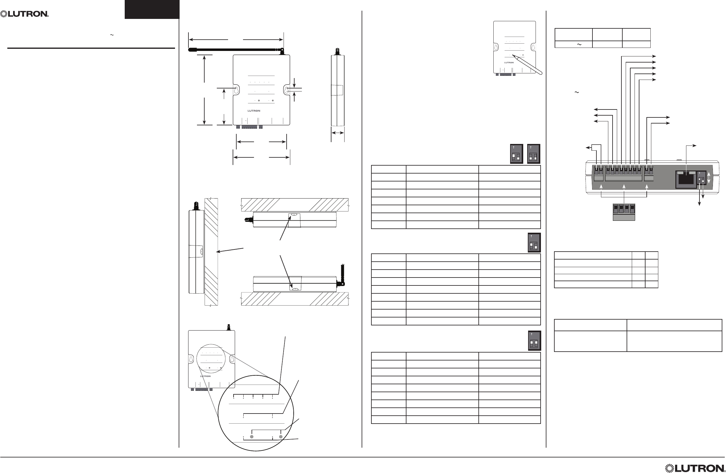
Front View Side View
2
3⁄4
(70)
6
1⁄4
(159)
1/4
(6)
4
1⁄4
(108)
1
1⁄16
(27)
3
3⁄4
(95)
Mounting Holes
5
1⁄4
(133)
Dimensions Measurements shown in inches (mm).
Mounting Diagram
Vertical Horizontal
Wall
Level Surface
#6 (M3) screw recommended
(2 included)
Ceiling
Relay Contact Ratings
Power 24 V
(from HVAC system transformers)
NEC® Class 2 / PELV cable
Wired Sensor
Connection for 2 wired sensors
Maximum 100 ft (30.5 m)
Contact Closure Terminal Blocks
NEC Class 2 / PELV cable
Maximum 1000 ft (305 m)
Each terminal holds up to one
16 AWG (1.0 mm2) or two 18 AWG (0.75 mm2)
or smaller wire.
W1 - Heat stage 1, auxiliary heat
W2 O/B -
Heat stage 2, changeover valve
G - Fan
Y1 - Compressor stage 1
Y2 - Compressor stage 2
HVAC Out
Terminal connections for connecting
to the HVAC system
PC Connection
Lutron use only.
S1
S2
HVAC Setup
2 dipswitches for selecting
HVAC system type
Jumper required
in single
transformaer
systems
Rc/Rh Jumper
Off
On
HVAC Controller
HVAC Controller Diagnostic Mode
The diagnostic mode is used to ensure the relays on the
HVAC controller are functioning and wired properly to
your HVAC system.
Follow the steps below to test your wiring using
diagnostic mode. There are three Diagnostic Mode
tests. The test that is cycled is determined by the 2
dipswitches on the HVAC Controller. The dipswitches
define whether the HVAC system is used with a
Conventional system or a Heat Pump system.
1. Enter HVAC Diagnostic Mode
Press and hold “Test” button for 10 seconds to enter Diagnostic Mode until
“Test” LED flashes rapidly. “Test” LED will flash slowly while in Diagnostic Mode.
2. Cycle through the test steps
The dipswitch settings determine which test cycle will be run. Tap the “Test”
button to advance through the diagnostic steps. Use the tables below to
determine the test sequence that will be run on your system. Each tap moves
the HVAC controller to the next step and will turn on and off different relays
and corresponding LEDS. At each step, the thermostat wiring can be verified.
NOTE: There is a 20 second minimum delay between each step.
3. Exit HVAC Diagnostic Mode
At any time, press and hold “Test” button for 10 seconds to exit Diagnostic
Mode. If no button is pressed for 3 minutes, the HVAC Controller will exit
Diagnostic Mode.
Setup
Power HVAC Out
W1
O/B
W2 GY1
LinkTest
Y2
Y1
G
W1 W2
O/B
HVAC Controller
HVAC System Status
Y2
Remote
R1 R2
RS485
S1 S2
CRh
Rc
Remote Sensor Status
Active Battery Low
Rc/Rh
Jumper 24 V Sensor
Setup
Voltage Resistive
Load
Inductive
Load
Up to 24 V 1 A 0.1 A
Table 4
System Configuration S1 S2
Standard - Gas (Default) Off Off
Heat Pump - Changeover Cool Off On
Standard - Electric On Off
Heat Pump - Changeover Heat On On
Table 5
Test and Link Buttons
Press and hold to troubleshoot
(Test) and set up (Add) the
RF connection.
Test and Link LEDs
Flashes green to indicate that
the system is in Test mode or
Add mode.
HVAC System Status LEDs
Indicate the status of the control outputs.
When an LED is lit the corresponding relay
is closed.
W1 - Heat stage 1, auxiliary heat
W2 O/B - Heat stage 2, changeover valve
G - Fan
Y1 - Compressor stage 1
Y2 - Compressor stage 2
Remote Sensor Status LEDs
Battery Low - LED flashes slowly
to indicate that at least one
associated Wireless Temperature
Sensor has a low battery.
Active - LED is lit if at least one
Wireless Temperature Sensor is
active.
Symptom Probable Cause and Action
LEDs on the HVAC Controller
do not turn on when it is
powered up.
Power Not Present
• Circuit Breaker is OFF or tripped. Reset
or turn on circuit breaker.
Heat Transformer - Rh
Cool Transformer - Rc
Common - C
1 2
ON
1 2
ON
1 2
ON
Step 1 All Off All Off
Step 2 Heat Stage 1 and Fan On W1 and G On
Step 3 Heat Stage 1 & 2 and Fan On W1, W2 (O/B), and G On
Step 4 All Off All Off
Step 5 Cool Stage 1 and Fan On G and Y1 On
Step 6 Cool Stage 1 & 2 and Fan On G, Y1, and Y2 On
Step 7 All Off All Off
Step 8 Fan On G On
Table 1 Conventional System Diagnostic Test Cycle
(Dipswitches: S1 = On or Off, S2 = Off)
1 2
ON
Step 1 All Off All Off
Step 2 Heat Stage 1 and Fan On G and Y1 On
Step 3 Heat Stage 1 & 2 and Fan On G, Y1, and Y2 On
Step 4 Auxiliary Heat On W1 and G On
Step 5 All Off All Off
Step 6 Cool Stage 1 and Fan On W2 (O/B), G, and Y1 On
Step 7 Cool Stage 1 & 2 and Fan On W2 (O/B), G, Y1, and Y2 On
Step 8 All Off All Off
Step 9 Fan On G On
Table 2 Heat Pump System Diagnostic Test Cycle
(Dipswitch S1 = Off, S2=On)
1 2
ON
Step 1 All Off All Off
Step 2 Heat Stage 1 and Fan On W2 (O/B), G, and Y1 On
Step 3 Heat Stage 1 & 2 and Fan On W2 (O/B), G, Y1, and Y2 On
Step 4 Auxiliary Heat On W1 and G On
Step 5 All Off All Off
Step 6 Cool Stage 1 and Fan On G and Y1 On
Step 7 Cool Stage 1 & 2 and Fan On G, Y1, and Y2 On
Step 8 All Off All Off
Step 9 Fan On G On
Table 3 Heat Pump System Diagnostic Test Cycle
(Dipswitch S1 = On, S2=On)
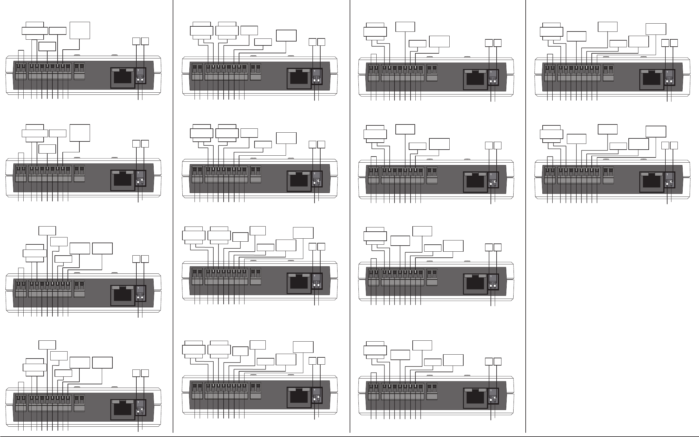
Wiring Your System
Conventional System
Conventional Gas/Oil Heat System • 1 Stage Heat / 1 Stage Cool
1 2
ON
CRcRhW1W2GY1 Y2Rc Rh S2 S1
Jumper Heat
Stage 1
CompressorFan Relay
Off Off
Transformer
Conventional Gas/Oil Heat System • 1 Stage Heat / 1 Stage Cool, 2 Transformers
1 2
ON
CRcRhW1W2GY1 Y2Rc Rh
Heat
Stage 1
Compressor
Fan Relay Off Off
Cool
Transformer
Heat
Transformer
S2 S1
Single Stage Heat Pump (Changeover = Cool)
1 2
ON
CRcRhW1W2GY1 Y2Rc Rh
Jumper
Changeover
Valve
Compressor
Fan Relay Off Off
Transformer
S2 S1
2 Stage Heat Pump w/ Auxiliary Heat (Changeover = Cool)
1 2
ON
CRcRhW1W2GY1 Y2Rc Rh
Jumper
Changeover
Valve
Compressor
Stage 1
Compressor
Stage 2
Fan Relay Off Off
Transformer Auxilary
Heat
S2 S1
Conventional Gas/Oil Heat System • 2 Stage Heat / 2 Stage Cool
1 2
ON
CRcRhW1W2GY1 Y2Rc Rh
Jumper
Heat
Stage 1
Heat
Stage 2Compressor
Stage 1
Compressor
Stage 2
Fan Relay Off Off
Transformer
S2 S1
Conventional Gas/Oil Heat System • 2 Stage Heat / 2 Stage Cool, 2 Transformers
1 2
ON
CRcRhW1W2GY1 Y2Rc Rh
Heat
Stage 1
Heat
Stage 2
Compressor
Stage 1
Compressor
Stage 2
Fan Relay Off Off
Cool
Transformer
Heat
Transformer
S2 S1
Single Stage Heat Pump w/ Auxiliary Heat (Changeover = Cool)
1 2
ON
CRcRhW1W2GY1 Y2Rc Rh
Jumper
Changeover
Valve
Fan Relay Off Off
Transformer Auxilary
Heat
Compressor
S2 S1
Conventional Electric Heat System • 1 Stage Heat / 1 Stage Cool
1 2
ON
CRcRhW1W2GY1 Y2Rc Rh S2 S1
Jumper Heat
Stage 1
CompressorFan Relay
Off On
Transformer
Conventional Electric Heat System • 1 Stage Heat / 1 Stage Cool, 2 Transformers
1 2
ON
CRcRhW1W2GY1 Y2Rc Rh S2 S1
Heat
Stage 1
Compressor
Fan Relay Off On
Cool
Transformer
Heat
Transformer
Single Stage Heat Pump (Changeover = Heat)
1 2
ON
CRcRhW1W2GY1 Y2Rc Rh S2 S1
Jumper
Changeover
Valve
Compressor
Fan Relay Off On
Transformer
2 Stage Heat Pump w/ Auxiliary Heat (Changeover = Heat)
1 2
ON
CRcRhW1W2GY1 Y2Rc Rh S2 S1
Jumper
Changeover
Valve
Compressor
Stage 1
Compressor
Stage 2
Fan Relay Off On
Transformer Auxilary
Heat
Conventional Electric Heat System • 2 Stage Heat / 2 Stage Cool
1 2
ON
CRcRhW1W2GY1 Y2Rc Rh S2 S1
Jumper
Heat
Stage 1
Heat
Stage 2Compressor
Stage 1
Compressor
Stage 2
Fan Relay Off On
Transformer
Conventional Electric Heat System • 2 Stage Heat / 2 Stage Cool, 2 Transformers
1 2
ON
CRcRhW1W2GY1 Y2Rc Rh S2 S1
Heat
Stage 1
Heat
Stage 2
Compressor
Stage 1
Compressor
Stage 2
Fan Relay Off On
Cool
Transformer
Heat
Transformer
Single Stage Heat Pump w/ Auxiliary Heat (Changeover = Heat)
1 2
ON
CRcRhW1W2GY1 Y2Rc Rh S2 S1
Jumper
Changeover
Valve
Compressor
Fan Relay Off On
Transformer Auxilary
Heat
Conventional System (continued) Heat Pump System (continued) Heat Pump System