Lutron Electronics 0074 RF Theromstat User Manual
Lutron Electronics Company Inc RF Theromstat
Contents
- 1. user manual
- 2. manual
user manual
English
Important Notes
Codes: Install in accordance with all local and national electrical codes.
Environment: Ambient operating temperature: 32 °F to 104 °F (0 °C to 40 °C),
0 to 90% humidity, non-condensing. Indoor use only.
Wallplates: Use only Lutron® wallplates with these devices. The mechanical design of the
seeTemp Wall Display is NOT compatible with non-Lutron wallplates. Non-Lutron wallplates
will NOT sit flush against the wall. Claro® and Satin Colors® wallplates are strongly
recommended for best color match and clean aesthetic appearance. Do not paint controls, buttons,
or wallplates.
Cleaning: To clean, wipe with a clean damp cloth. DO NOT use any chemical cleaning solutions.
Wallboxes: All seeTemp Wall Display units require a U.S. wallbox. 3 1⁄2 in (89 mm) deep
recommended, 2 1⁄4 in (57 mm) deep minimum.
RF Device Placement: RF must be located within 30 ft (9 m) of an RF signal repeater. Troubleshooting Guide for seeTemp Wall Display
Symptom Probable Cause and Action
LEDs on a seeTemp Wall Display don’t light
up when the buttons on it are pressed.
Power not present at seeTemp Wall Display
• Circuit breaker OFF. Turn ON breaker.
Incorrect wiring.
• Wire the seeTemp Wall Display according to the
Installation section.
HVAC controller not controlled by a
seeTemp Wall Display and/or temperature is
not changing.
The HVAC controller is not assigned to a seeTemp Wall
Display.
• Follow the steps in Programming.
There is no power to the device.
• Ensure that the device is powered
Temperature may take up to 20 minutes to change in
the space
HVAC equipment does not have enough power and can’t
reach setpoint
6 LEDs on the seeTemp Wall Display flash
when any button is pressed.
The seeTemp Wall Display is in the Factory Settings mode
and has not been congured to work in a system.
• Follow the steps in Programming.
Room Temperature LED flashes rapidly. Low battery on Wireless Temperature Sensor.
• Replace battery in Wireless Temperature Sensor.
Set temperature LED flashes rapidly. The seeTemp Wall Display is hearing the wired backup
sensor and cannot hear Wireless Temperature Sensor.
• Move Wireless Temperature Sensor closer to a repeater.
Room LED scrolls up and down. No Wireless Temperature Sensor or wired backup is
present.
• Replace battery in Wireless Temperature Sensor.
• Add a Wireless Temperature Sensor.
• Add a wired backup sensor.
Room and set LED scrolls up and down
when button is pressed.
Communication Error.
• Move a repeater closer to a seeTemp Wall Display.
Returning a seeTemp Wall Display to Factory Settings
Returning a seeTemp Wall Display to its Factory Settings will remove the seeTemp Wall Display from the
system and erase all programming.
Step 1: Triple tap the ECO button on the seeTemp Wall Display. DO NOT release after third tap.
Step 2: Keep the button pressed on the third tap until all the status LEDs start to flash slowly (approximately
3 seconds).
Step 3:
Immediately release the button and triple tap the button again. The status LEDs on the
seeTemp Wall
Display
will flash quickly.
The seeTemp Wall Display has now been returned to Factory Settings.
Warranty:
For warranty information, please see the Warranty enclosed with the product, or visit
www.lutron.com/resiinfo
Installation Instructions
Please Read Before Installing
Lutron Elec tron ics Co., Inc.
7200 Suter Road | Coopersburg, PA 18036-1299
Print ed in the U.S.A. 11/2010 P/N 041-298 Rev. A
Technical Assistance | 24 hours a day, 7 days a week | www.lutron.com
U.S.A. / Canada: 1.800.523.9466 | Mexico: +1.888.235.2910 | Other Countries: +1.610.282.3800
seeTemp™ Wall Display
LRD-WST-F, LRD-WST-C
24 V or 120 V 50 / 60 Hz 0.1 A
Typical Power Consumption*: 1 W
eco
Installation
WARNING: Shock Hazard. To avoid the risk of electric shock, locate and
remove fuse or lock circuit breaker in the OFF position before proceeding.
Wiring with power ON could result in serious injury or death.
1. Turn power OFF at fusebox or circuit breaker.
2. Prepare wires. When making wire connections, follow the recommended strip lengths and combinations
for the supplied wire connectors. Note: Wire connectors provided are suitable for copper wire only.
• Strip insulation 3/8 in (10 mm) for 14 AWG (1.5 mm2).
• Strip insulation 1/2 in (13 mm) for 18 AWG (0.75 mm2).
• Use to join one 14 AWG (1.5 mm2) with one 18 AWG (0.75 mm2) wires.
3. Wire control.
OFF OFF OFF
ONONON
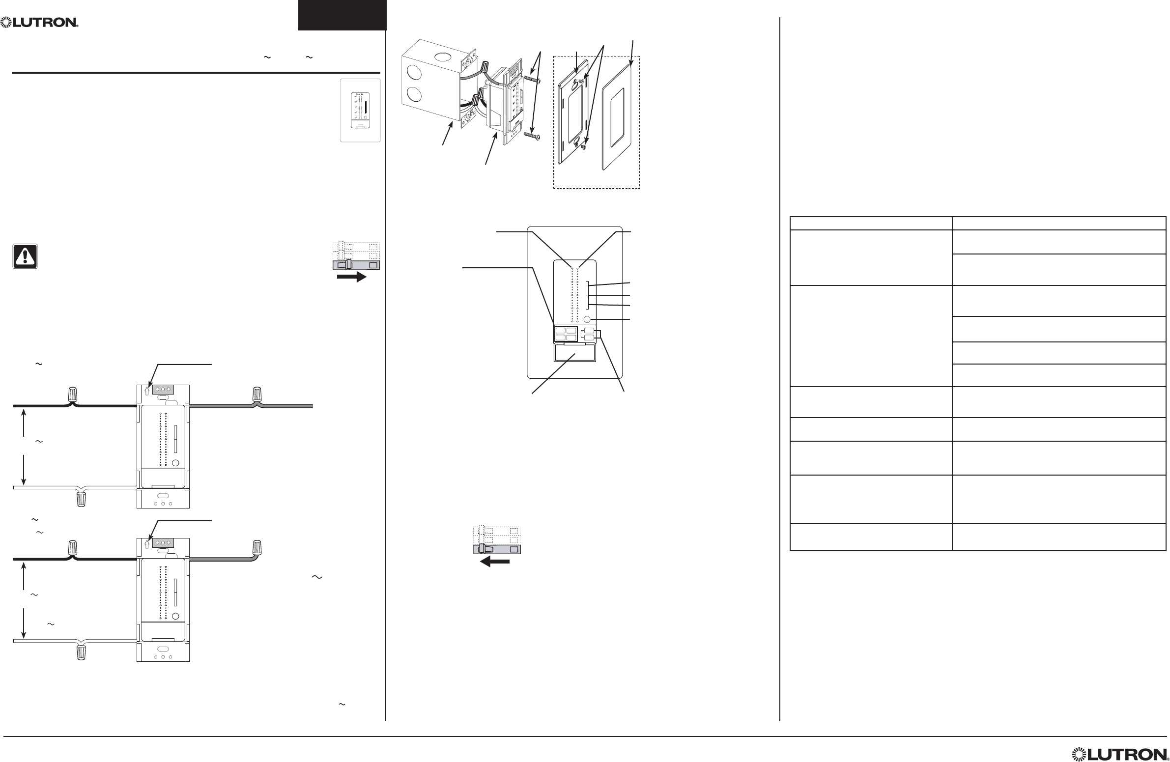
4. Push all wires back into the wallbox and loosely fasten the control to the wallbox using the seeTemp
Wall Display mounting screws provided. Do not pinch the wires. See Mounting Diagram below.
5. Attach Lutron Claro or Satin Colors wallplate adapter and wallplate (see Mounting Diagram).
a. Install the wallplate adapter onto the front of the seeTemp Wall Display.
b. Tighten mounting screws until wallplate adapter is flush to wall (do not over-tighten).
c. Snap wallplate onto wallplate adapter and verify that the color replacement kit is aligned properly.
d. If control(s) are misaligned, loosen mounting screws appropriately.
6. Restore power.
ON
OFF
ON
OFF
ON
OFF
seeTemp
Wall Display
Wallbox
Mounting
Screws
Adapter
Mounting
Screws
Wallplate adapter and wallplate
purchased separately.
Mounting Diagram
Wallplate
Adapter
Wallplate
Heat
Auto
On
Auto
Fan
Cool
Off
Room Set
80°
75°
70°
65°
60°
eco
Set Temperature LEDs
Column of LEDs that display the
current set temperature point. Set LED
turns off when system is turned off.
Raise/Lower Rocker
Flip-Down Door
Covers the System and
Fan buttons. Opens 180°.
seeTemp® Wall Display
Eco Button
Press to toggle Eco mode on/off.
Fan Buttons
Indicates the current fan setting. Button
will light up when selected.
On – Fan is constantly on.
Auto – Fan is on only when Heat/Cool
is active.
System Buttons
Indicates the current system
setting. When selected,
buttons will light up according
to the following:
Heat - Red
Cool - Blue
Auto - Orange
Off - Orange
Room Temperature LEDs
Column of LEDs that display
the current room temperature.
Press to lower the Set temperature.
Press to raise the Set temperature.
120 V Wiring
LUTRON
Room Set
80°
75°
70°
65°
60°
eco
NOTE: Orientation arrow
MUST point UP.
120 V
50 / 60 Hz
Hot/Live Black Green Ground
Neutral White
24 V Wiring
LUTRON
Room Set
80°
75°
70°
65°
60°
eco
NOTE: Orientation arrow
MUST point UP.
24 V
50 / 60 Hz
24 V
Common
Black Green
White
* Cap ground wire for 24 V
wiring applications.
*
24 V
from HVAC
equipment
* Typical Power Consumption test conditions: all backlights on medium intensity, two LEDs on seeTemp Wall Display powered at 120 V
Programming
After installation, the HVAC controller (LR-HVAC) will only function when programmed to a system with
a seeTemp™ Wall Display (LRD-WST). For full functionality, the HVAC Controller must be programmed
to a RadioRA® 2 Main Repeater (RR-MAIN-REP) and PC software must be used by a Lutron factory-
trained installer. For questions on how to become a qualified installer, please contact your local Lutron
representative.
Temporary Programming
Since the HVAC system may need to function before a Lutron factory-trained installer is available for
programming, temporary programming may be used to provide climate control.
To complete the steps below, the following are required: RadioRA 2 Main Repeater (RR-MAIN-REP)
within 30 ft of the HVAC controller, seeTemp unit(s), and Wireless Temperature sensor(s).
1. Enter Add Mode: Press and hold the “Add” button on Main Repeater for 3 seconds until green “Add”
LED begins to rapid-flash (ten times per second) and repeater beeps. Wait 10 seconds.
Temporary Programming (continued)
2. Add the devices to the Main Repeater:
a. For the HVAC controller, press and hold the Link button for 3 seconds until all LEDs normal-flash
(once per second).
b. For the seeTemp, press and hold the Eco button for 3 seconds until all LEDs normal-flash (once
per second).
c. For the Wireless Temperature Sensor, press and hold the Link button for 6 seconds until the hidden
LED flashes (once per second).
3. Exit Add Mode: Press and hold the “Add” button on any Repeater for 3 seconds until “Add” LED
begins to rapid-flash. After LED turns off (can take up to 30–60 seconds), system has exited Add
Mode.
4. Test the system:
a. Set the seeTemp to Heat or Cool mode.
b. Tap the link button on the Wireless Temperature Sensor. The Temperature will update on the
seeTemp.
c. As the temperature changes, the HVAC controller will control the HVAC equipment when required.