Lutron Electronics 0077 Low Power Communication Device Transmitter User Manual 9510 0712 ai
Lutron Electronics Company Inc Low Power Communication Device Transmitter 9510 0712 ai
Contents
- 1. User Manual 1
- 2. User Manual 2
User Manual 1
Specifications:
Temperature Monitor Range: 32.2°F to 99.9°F (0.0°C to 37.7°C)
Setpoint Range: 60.0°F to 85.0°F (15.5°C to 29.5°C)
*Setpoint: 72°F (22°C)
*Comfort Limits: 65.0°F (18.5°C) cooling
85.0°F (29.5°C) heating
Display Format: Liquid Crystal Display (LCD)
Backlight: EL blue green
Sampling Rate: Every 15 seconds
Accuracy: ± 1°F (0.5°C)
Power Source: 24VAC/DC (20 minimum to 32 maximum)
Load Rating: 1.5 amps per load circuit
*Fan Control: Selectable: Auto cycle, Low, Medium, High
Heat/Cool Control: 1 heat and 1 cool circuit (see system function)
*Economy Limits:
Maintains room temperature between 60.0°F and 85.0°F
(15.5°C and 29.5°C) when thermostat is in economy (ECON) mode
*Fan Purge Timer: 30 seconds
Anti-short Cycle: 3 minute hold in no call state at all times
*Cycle Rate: 8 cycles per hour
* Differential: 0.4°F
* Display Mode: Setpoint temperature
* System Function: Heat and Cool
*See Field Programming Instructions
Application:
This thermostat is a 24 volt heating and cooling digital temperature
control designed to operate 2 or 4-pipe fan coil systems. Switching
of load circuits is through relay contacts. Fan outputs can be
configured to operate 3, 2 or single speed fan motors. The fan control
also has configurations for user select fan speed with economy
function, continuous fan or auto cycle fan. This thermostat operates
on a single setpoint with automatic changeover from heating to cooling.
Installation Notice:
This high performance digital thermostat is designed to provide many
years of superior comfort control when properly installed and maintained.
To achieve maximum performance, this device is designed to draw
room air into itself continuously. Reasonable care must therefore be
taken with regard to air quality at the time of installation as well as
during periods of normal use, see operating conditions below.
Operating Conditions:
The electronic mechanisms incorporated within this unit REQUIRE
operating conditions similar to other electronic devices intended for
INDOOR USE ONLY, such as would be acceptable for TV and similar
household appliances. Relative humidity must be less than 95% and
the atmosphere must be non-condensing. For operation in bathrooms,
shower or pool areas, outdoor entry ways, greenhouses and similar
applications, order the “-k” option. This product includes protection
for coastal/tropical application, therefore it is suitable for use in high
humidity environments. Air quality must be maintained FREE of heavy
dust or debris which may infiltrate the interior of this device. Installation
in any space which is unfinished or undergoing repainting or general
rehabilitation is also considered product abuse. This device should be
removed from service during any local construction activity.
Cleaning:
This device incorporates a high impact polycarbonate enclosure which
is easily cleaned with a dry cloth or vacuum brush. Occasional soiling
may be cleaned with a soft cloth lightly dampened with water and/or
mild cleaning solution. IN NO CASE should this device be directly
sprayed with or exposed to free flowing liquids, including water, which
could penetrate its interior.
FAILURE TO OBSERVE ANY OF THE ABOVE CONDITIONS OF USE
WILL COMPLETELY VOID THE SUPPLIER WARRANTY.
CAUTION
MAKE SURE UNIT IS PROPERLY CONNECTED. DAMAGE TO THE
DIGITAL CONTROL CAN BE CAUSED BY MISWIRING, WHICH WILL
VOID THE WARRANTY. FOR SAFETY REASONS ALWAYS USE
WIRE NUTS ON ALL WIRE CONNECTIONS!!!
◦
+3V
SB1
SB2
COM
SEN3
SEN2
REF
+3V
SB1
SB2
COM
+3V
SB1
SB2
COM
◦
◦
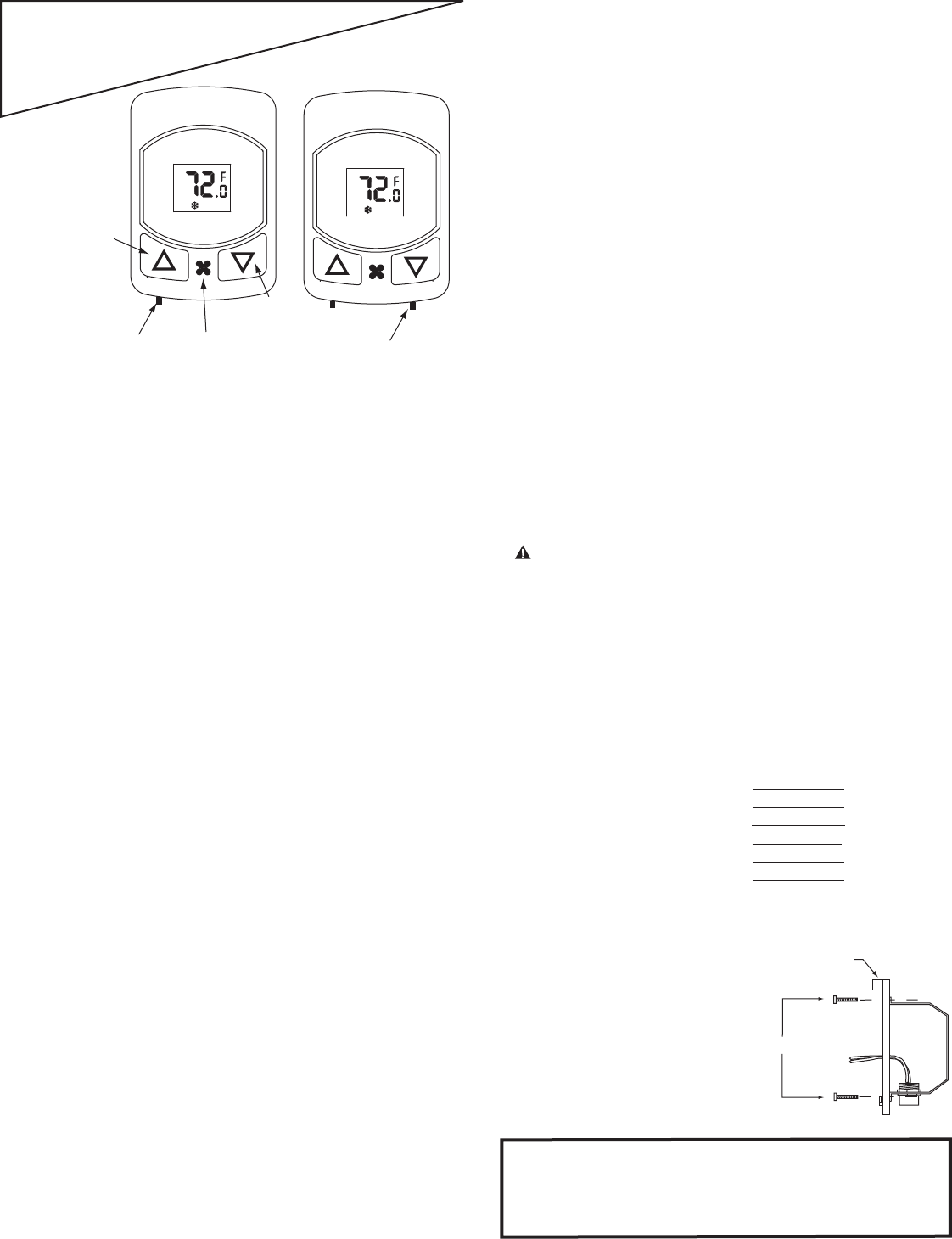
Installation and Operating Instructions
Premier Series
24 Volt PFC-M24
PFC-M24-RS
SETPOINT
AUTO
◦
◦
System Mode
Switch
H
E
A
T
/
A
U
T
O
/
C
O
O
L
°
F
/°
C
PFC-A24
PFC-A24-RS
SETPOINT
AUTO
◦
◦
Decrease
temperature
Switches between
°F and °C
Selects
fan
function
Increase
temperature
°
F
/°
C
4-PIPE FAN COIL, 2-PIPE ELECTRIC HEAT OR
ELECTRONIC AQUASTAT INSTALLATION:
This device should be installed and serviced by a qualified technician.
Junction box mounting is highly recommended.
1. Caution: Make sure that power has been disconnected.
2. All wiring must comply with applicable codes and ordinances.
3. A thorough check-out of the system should be made after
installation is complete.
4. If fan motor is larger than 1/4 HP and/or electric heaters are used
for heating, additional power relays will be required
5. If retrofitting old thermostat, remove old thermostat from the
junction box, carefully noting the wire connections on the old unit.
Record wire color and terminal legends in spaces provided.
Disconnect old thermostat and remove any existing backplate or
mounting plate.
Old thermostat
wire function
Power Feed
Common
Heat
Cool
Low Fan
Medium Fan
High Fan
Cable
wire color
User Note: The top of this unit will become warm to the touch. This is a
normal operation. Internal heating is employed to continuously convect
air upward through the thermostat, thereby improving room air temperature
measurement. Direct conflict with a downward ceiling fan or system fan air
flow may result in false temperature reading. Locate thermostat to avoid
interference.
Screw: 6/32 x 3/4"
Mounting Bracket
Standard
Junction
Box
6. Install the mounting bracket to the
junction box with the two long
mounting screws provided.
See mounting detail to the right.
Note: If application involves a
double ganged junction box,
a backplate will be required for a
complete installation.
Please consult your supplier.
1
◦
SEN3
SEN2
REF
+3V
SB1
SB2
COM
◦
◦
◦
New Stat Wire
Function
Control Feed
Load Feed
Common
Heat
Cool
Low Fan
Medium Fan
High Fan
New Stat Wire
Color
Red
Orange
Black
White
Yellow
Green
Blue
Violet
Cable Wire Color
7. From the wire chart found in step 5, assign, according to function,
the cable wire colors to the thermostat wire legend provided below.
Note: The control feed and the load feed will be connected together
for the 4-pipe installation. If this is a new installation, record the cable
wire colors in the thermostat legend provided below.
8. Connect the thermostat wires to the cable wires recorded in step 7.
NOTE: When the thermostat is programmed for 2 speed the High fan
wire will not be used. Also, when the thermostat is programmed for
single speed fan, only the low fan wire connection will be used. Isolate
any unused fan speed wires from the thermostat.
10. Turn power on.
At start up, the low fan will automatically run for three minutes to
cycle room air.
If cooling or heating is required, it may become active after the
first 30 seconds of fan run time.
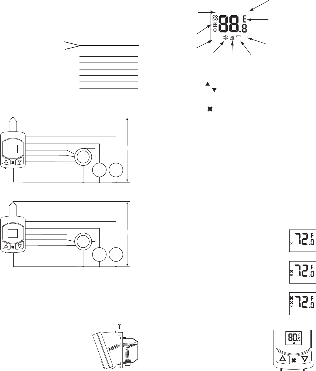
Room
Temperature
Indicator
Fan
Icons
Mode
Icons Cool
Icon Heat
Icon
Diagnostic
Indicator
Programming
Icons
Scale Indicator
Setpoint
Indicator
ROOM SETPOINT
AUTO
ECON
PROG
ERASE
DIAG
◦
◦
+3V
SB1
SB2
COM
SEN3
SEN2
REF
+3V
SB1
SB2
COM
+3V
SB1
SB2
COM
◦
◦
◦
◦
2
Red Wiring Diagram 4-pipe Fan Coil
3 Speed Fan (default configuration)
Violet HIGH 24VAC
Blue MEDIUM
White
Orange
Black
Yellow
Green LOW Fan
Cool
Valve Heat
Valve
Common
Feed
Red Wiring Diagram 4-pipe Fan Coil
2 Speed Fan (programmed setting)
Violet NOT USED 24VAC
Blue MEDIUM
White
Orange
Black
Yellow
Green LOW Fan
Cool
Valve Heat
Valve
Common
Feed
9. Push the wires into the junction box. Tilt
the thermostat so that the bottom of the
thermostat is resting on the mounting tabs
of the mounting plate. Push the top of the
thermostat towards the wall and secure into
place with the self-tapping screw as shown
to the right.
Standard
Junction
box
NOTE: For more details on Electronic Aquastat installions, refer to
Remote Sensor/Aquastat Option on page 5.
BASIC FUNCTIONS
Adjust Temperature Setpoint:
Press up button ( ) to raise the temperature (warmer)
Press down button ( ) to lower the temperature (cooler)
Select Fan Operation:
Press fan button ( ) to select the following fan functions*
Continuous HIGH speed fan
Continuous Medium speed fan
Continuous LOW speed fan
AUTO on/off with automatic speed change
ECON, economy function
*fan function sequence with auto as the starting point
Change Scale Units:
Slide the °F/°C switch to the left to display °F
Slide the °F/°C switch to the right to display °C
When the °F/°C switch is invoked, the thermostat will reset and
display the default setpoint in the selected scale.
Cycle Timing: (Anti-short cycle protection)
3 minute (minimum) dwell time in no-call states (both heat and cool).
1 minute (minimum) dwell time in call states (both heat and cool).
Temperature is sampled every 15 seconds.
9510-0712
Rev D 10-23-07
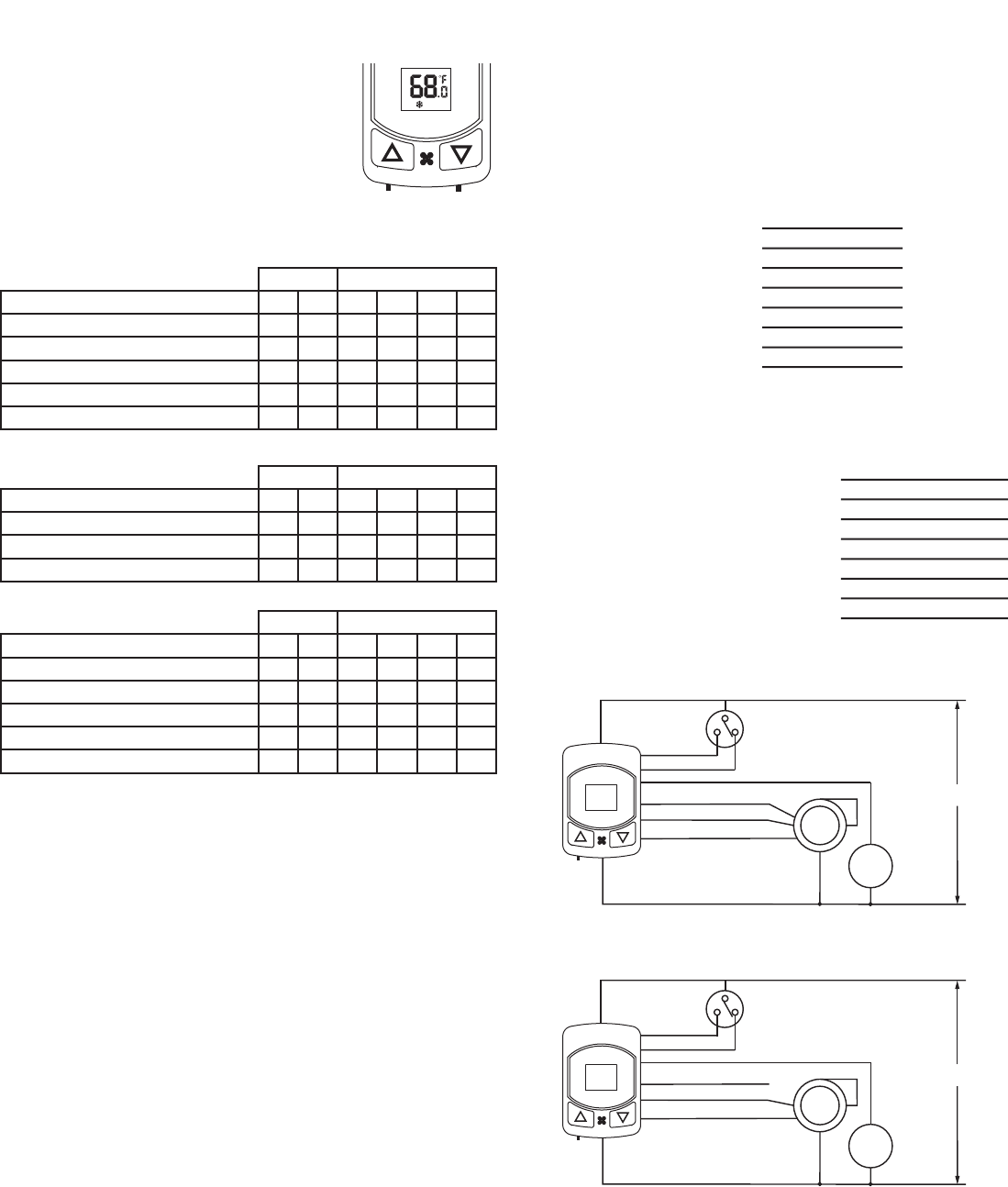
Check Heating:
Press and hold the up button until the heat
symbol appears on the LCD. Within 4 seconds
the heat valve will be activated. For manual
changeover models place the system mode
switch in the heat or auto position.
Note: Room temperature must be below
the Comfort Heating Limit 85.0°F (29.5°C)
for heating to become active.
H
E
A
T
/
A
U
T
O
/
C
O
O
L
°
F
/
°
C
SETPOINT
AUTO
◦
SEN3
SEN2
REF
+3V
SB1
SB2
COM
Check Low Fan Function:
Press the fan button. One fan symbol will appear
on the LCD. Low fan speed will turn on immediately.
Medium or high fan, if active, will turn off.
SETPOINT
◦
◦
Check Medium Fan Function:
Press the fan button. Two fan symbols will appear
on the LCD. Low fan will turn off and medium fan
will turn on immediately.
SETPOINT
◦
◦
Check High Fan Function:
Press the fan button. Three fan symbols will appear
on the LCD. Medium fan will turn off and high fan
will turn on immediately.
SETPOINT
◦
◦
◦
TROUBLE SHOOTING TESTS (4-Pipe System)
Voltage: When using a voltmeter across "Black" and "Red" and
“Black” to “Orange”, voltage must be 24VAC.
To Check Continuity: (Using a Voltmeter with all loads connected)
A) When the thermostat is calling for Cooling, meter should read
24VAC from “Black” to “Yellow”. When cooling is deactivated,
meter should read 0VAC from “Black” to “Yellow”.
B) When the thermostat is calling for Heating, meter should read
24VAC from “Black” to “White”. When heating is deactivated,
meter should read 0VAC from “Black” to “White”.
C) When the thermostat is calling for High Fan, meter should read
24VAC from “Black” to “Violet”. When all fan speeds are turned
off, meter should read 0VAC from “Black” to “Violet”.
D) When the thermostat is calling for Medium Fan, meter should read
24VAC from “Black” to “Blue”. When all fan speeds are turned off,
meter should read 0VAC from “Black” to “Blue”.
E) When the thermostat is calling for Low Fan, meter should read
24VAC from “Black” to “Green”. When all fan speeds are turned
off, meter should read 0VAC from “Black” to “Green”.
2-PIPE FAN COIL INSTALLATION: (Bimetal Aquastat ONLY)
NOTE: For Electronic Aquastat applications (RS models) use the
4-Pipe wiring ONLY.
Follow the instructions for a 4-pipe installation with the following
exceptions:
Old Thermostat
Function
Control Feed
Common
Water Valve
Aquastat Heat
Aquastat Cool
Low Fan
Medium Fan
High Fan
Cable Wire Color
New Stat Wire
Function
Control Feed
Common
Load Feed (valve)
Aquastat Heat
Aquastat Cool
Low Fan
Medium Fan
High Fan
New Stat Wire
Color
Red
Black
Orange
White
Yellow
Green
Blue
Violet
Cable Wire Color
NOTE: When the thermostat is programmed for 2 speed the High fan
wire will not be used. Also, when the thermostat is programmed for
single speed fan, only the low fan wire connection will be used. Isolate
any unused fan speed wires from the thermostat.
+3V
SB1
SB2
COM
SEN3
SEN2
REF
+3V
SB1
SB2
COM
+3V
SB1
SB2
COM
◦
◦
◦
◦
3 9510-0712
Rev D 10-23-07
H
E
A
T
/
A
U
T
O
/
C
O
O
L
°
F
/
°
C
SETPOINT
AUTO
Check Cooling:
Press and hold the down button until the cool
symbol appears on the LCD. Within 4 seconds
the cool valve will be activated. For manual
changeover models place the system mode
switch in the cool or auto position.
Note: Room temperature must be above
the Comfort Cooling Limit 65°F (18.5°C)
for cooling to become active.
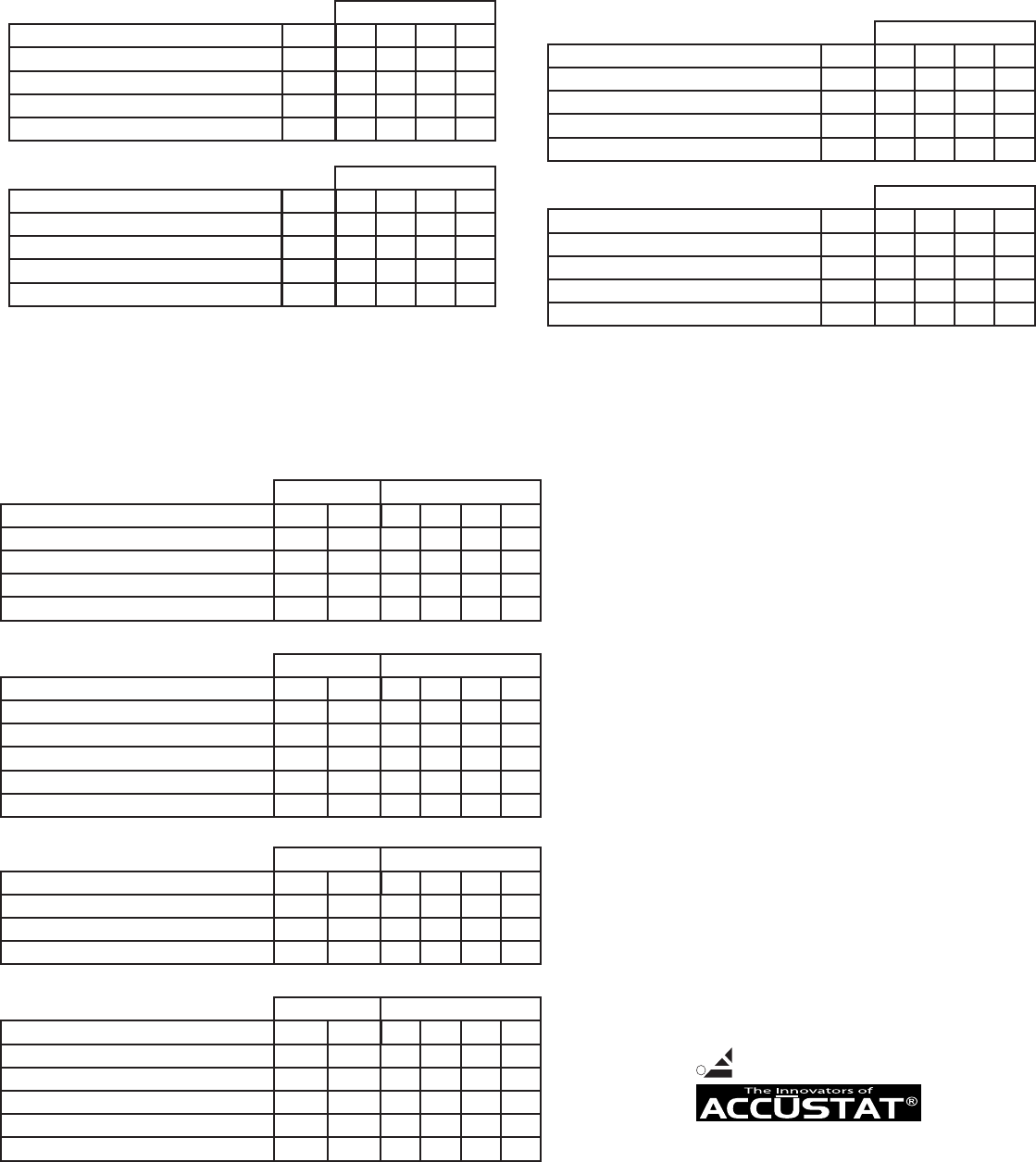
Adjust setpoint as follows:
6.0°F or more ABOVE room temperature
3.0°F to 5.9°F ABOVE room temperature
0.4°F BELOW to 2.9°F ABOVE room temperature
1.9°F to 0.4°F BELOW room temperature
2.0°F BELOW room temperature (cool threshold)
Heating Currently Active
FUNCTION CHART
MED
Lo Hi Med
Lo Med Med
Lo Med
Lo Off Med
Lo Med
HIGH
Hi
Hi
Hi
Hi
Hi Lo
On
On
On
Off
Reset Set
LOW AUTO COOL HEAT
FAN SPEED SYSTEM
Lo
Adjust setpoint as follows:
2.0°F ABOVE room temperature
1.9°F ABOVE to 1.9°F BELOW room temperature
2.0°F BELOW room temperature
Heating or Cooling Not Currently Active
MED
Lo Lo Med
Lo Off Med
Lo Med
HIGH
Hi
Hi
Hi
Set
Off Off
Set
LOW AUTO COOL HEAT
FAN SPEED SYSTEM
Lo
Adjust setpoint as follows:
2.0°F ABOVE room temperature (heat threshold)
1.9°F to 0.4°F ABOVE room temperature
0.4°F ABOVE to 2.9°F BELOW room temperature
3.0°F down to 5.9°F BELOW room temperature
6.0°F or more BELOW room temperature
Cooling Currently Active
MED
Lo Lo Med
Lo Off Med
Lo Med
Lo Med Med
Lo Med
HIGH
Hi
Hi
Hi
Hi
Hi Hi
Set Reset
Off
On
On
On
LOW AUTO COOL HEAT
FAN SPEED SYSTEM
Lo
◦
SEN3
SEN2
REF
+3V
SB1
SB2
COM
◦
◦
◦
Red
Wiring Diagram 2-pipe
Fan Coil with 3 Speed Fan
24VAC
Black
Green LOW
Blue MEDIUM
Violet HIGH
Orange
Yellow
White
Fan
Valve
Common
Feed
Aquastat (mounted on water
supply line) or season change
switch
Red
Wiring Diagram 2-pipe
Fan Coil with 2 Speed Fan
24VAC
Black
Green LOW
Blue MEDIUM
Violet NOT USED
Orange
Yellow
White
Fan
Valve
Common
Feed
Aquastat (mounted on water
supply line) or season change
switch
◦
TROUBLE SHOOTING TESTS (2-Pipe System)
Voltage: When using a voltmeter across “Black" and "Red", voltage
must be 24VAC.
To Check Continuity: (Using a Voltmeter with all loads connected)
Cold pipe or season switch set to cool: (power supplied through
yellow wire)
A) When the thermostat is calling for cooling and low fan, meter
should read 24VAC from “Black” to “Orange” and from “Black” to
“Green”. When cooling is deactivated, meter should read 0VAC
from “Black” to “Orange” and “Black” to “Green”.
B) When the thermostat is calling for cooling and medium fan,
meter should read 24VAC from “Black” to “Orange” and from
“Black” to “Blue”. When cooling is deactivated, meter should read
0VAC from ”Black” to “Orange” and “Black” to “Blue”.
C) When the thermostat is calling for cooling and high fan, meter
should read 24VAC from “Black” to “Orange” and from “Black” to
“Violet”. When cooling is deactivated, meter should read 0VAC
from ”Black” to “Orange” and “Black” to “Violet”.
Hot pipe or season switch set to heat: (power supplied through white
wire)
A) When the thermostat is calling for heating and low fan, meter
should read 24VAC from “Black” to “Orange” and from “Black” to
“Green”. When heating is deactivated, meter should read 0VAC
from ”Black” to “Orange” and “Black” to “Green”.
B) When the thermostat is calling for heating and medium fan,
meter should read 24VAC from “Black” to “Orange” and from
“Black” to “Blue”. When heating is deactivated, meter should read
0VAC from ”Black” to “Orange” and “White” to “Blue”.
C) When the thermostat is calling for heating and high fan, meter
should read 24VAC from “Black” to “Orange” and from “Black” to
“Violet”. When heating is deactivated, meter should read 0VAC
from ”Black” to “Orange” and “Black” to “Violet”.
+3V
SB1
SB2
COM
SEN3
SEN2
REF
+3V
SB1
SB2
COM
+3V
SB1
SB2
COM
Diagnostic Mode:
Press and hold the "up" and "down" buttons
together until "DIAG" appears on the display.
Diagnostic mode will alternately display
setpoint and room temperature every 8 seconds.
SETPOINT
AUTO
DIAG
◦
◦
The current operating fan mode will also show.
Low speed fan will display a single fan icon,
two speed fan will display two fan icons and
three speed fan will display three fan icons.
ROOM
AUTO
DIAG
◦
◦
◦
◦
4
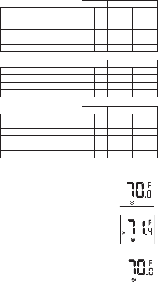
Adjust setpoint as follows:
6.0°F or more ABOVE room temperature
3.0°F to 5.9°F ABOVE room temperature
0.4°F BELOW to 2.9°F ABOVE room temperature
1.9°F to 0.4°F BELOW room temperature
2.0°F BELOW room temperature (cool threshold)
Heating Season, Hot Pipe
FUNCTION CHART
MED
Lo Hi Med
Lo Med Med
Lo Med
Off Off Off
Off Off
HIGH
Hi
Hi
Hi
Off
Off Off
On
On
On
Off
Reset Set
LOW AUTO COOL HEAT
FAN SPEED SYSTEM
Lo
Adjust setpoint as follows:
2.0°F ABOVE room temperature, Hot Pipe
1.9°F ABOVE to 1.9°F BELOW room temperature
2.0°F BELOW room temperature
Heating or Cooling Not Currently Active
MED
Lo Lo Med
Off Off Off
Lo Med
HIGH
Hi
Off
Hi
Set
Off Off
Set
LOW AUTO COOL HEAT
FAN SPEED SYSTEM
Lo
Adjust setpoint as follows:
2.0°F ABOVE room temperature (heat threshold)
1.9°F to 0.4°F ABOVE room temperature
0.4°F ABOVE to 2.9°F BELOW room temperature
3.0°F down to 5.9°F BELOW room temperature
6.0°F or more BELOW room temperature
Cooling Season, Cold Pipe
MED
Off Off Off
Off Off Off
Lo Med
Lo Med Med
Lo Med
HIGH
Off
Off
Hi
Hi
Hi Hi
Set Reset
Off
On
On
On
LOW AUTO COOL HEAT
FAN SPEED SYSTEM
Lo
SETPOINT
ECON
◦
◦
To deactivate the diagnostic mode, press the
"fan" button until the fan activity moves to
"ECON". "DIAG" will disappear from the display.
Press the "fan" button again to return to
operating mode.
Diagnostic mode can also be deactivated by
changing the °F/°C slide switch.
SEN3
SEN2
REF
+3V
SB1
SB2
COM
◦
◦
◦
◦
+3V
SB1
SB2
COM
SEN3
SEN2
REF
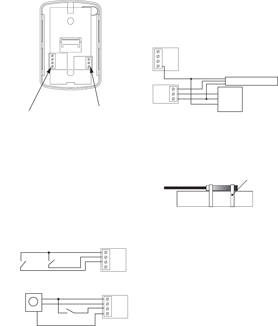
Optional remote functions
PFC-ALV-RS and PFC-MLV-RS models ONLY
Remote Setback
Terminal Block
Remote Sensor
Terminal Block
Remote Sensor/Aquastat Option:
The remote sensor option features a dual mode external sensor
function. SEN2 is to be used only as a room temperature sensor
(order PSG P-RS). SEN3 is to be used only with the Electronic
Aquastat Kit (order PSG P-AK). The REF terminal is common to
both sensor inputs. To activate the SEN2 or SEN3 terminals see
programming instructions. Both sensor functions may be used at
the same time, having both electronic aquastat and remote room
temperature capability. When the remote sensor is connected, it
may be used to control the thermostat instead of the on board
sensor or it may be averaged with the on board sensor. Use only
3 conductor cable or shielded 2 conductor cable. Connect the
shield or the third wire to the COM terminal.
Remote Setback/Shutdown Option:
The remote setback features a dual mode function. SB1 is the input
for remote setback (economy) and SB2 is the input for remote
shutdown mode. Setback mode when energized will remotely
place the thermostat in economy mode using the programmable
economy heat and cool setpoints. Shutdown mode when energized
will remotely place the thermostat in disable mode. The thermostat,
at this time, will not call for heating or cooling until taken out of shut-
down mode.
To activate the setback or shutdown mode use dry contacts (relays
or mechanical switch) to connect the +3V terminal to the appropriate
SB1 or SB2 terminal. An open circuit on SB1 or SB2 will disable the
remote function.
A COM terminal is provided for active type remote switch gear such
as the electronic motion sensor. Do not use the COM terminal for
any other application.
+3V
SB1
SB2
COM
door
switch
window
switch
Dry contact connections
+3V
SB1
SB2
COM
window
switch
(-)
(+3vdc)
Motion Sensor and dry contact
Motion
Sensor
◦
◦
Mount the Electronic Aquastat Sensor to the water pipe. The best
location is to be as close to the main pipe as possible and attached
before the water valve connection.
IMPORTANT:
The electronic aquastat sensor replaces the bimetal switch
which is common in most 2-pipe heat/cool fan coil systems.
This allows for the thermostat to directly control the equipment
as well as provide for alterations in change-over temperature
thresholds. Follow the standard 4-pipe wiring diagram. Cool
wire will control the heat/cool valve, the heat wire will operate
as an auxilliary electric heat switch (depending on fan coil
equipment).
Isolate all of the unused wires.
Water
Main Valve
Sensor Wire
Ties
◦
◦
5
◦
Refer to the programming instructions for selecting the aquastat
sensor function, temperature changeover settings, output configurations,
purge frequency and purge time duration. The thermostat will monitor
pipe temperature every 5 seconds. For a valvelss systems, select
the 2Pn configuration setting since this will bypass the valve purge
functions and provide heating or cooling based on pipe temperature
alone.
The 2PS and 2PE configurations operate with a valve purge function
to prevent incorrect temperature readings from static or standing water
in the pipe. The valve purge operates on a programmed interval
(purge frequency) for a programed duration (purge time duration)
in the event of low activity over an extended period of time.
If the heat or cool call has lasted for more than three minutes, the
pipe temperature heat or cool mode is rechecked to verify proper
operating mode.
Function charts on next page
SEN3
SEN2
REF
Room
Sensor
Aquastat Sensor
+3V
SB1
SB2
COM
◦
◦
◦
◦
+3V
SB1
SB2
COM
SEN3
SEN2
REF
+3V
SB1
SB2
COM
+3V
SB1
SB2
COM
◦
◦
◦
◦
PSG Controls, Inc.
LIMITED WARRANTY POLICY
PSG Controls, Inc. (Hereinafter referred to as "PSG") warrants the following:
Only cataloged products sold to distributors are warranted to the original purchaser,
to conform with specifications furnished or approved by PSG, and to be free from
defects in material and workmanship, for a period of one (1) year from the date of
purchase, unless specified in writing for a different period.
Any PSG product that proves defective within the above described warranty period
will be repaired or replaced (at PSG's option) free of any charge if returned to the
PSG factory at 1225 Tunnel Road, Perkasie, PA. 18944 with transportation charges
prepaid. Prior to returning this product to PSG, the purchaser shall give PSG notice
in writing stating how this product fails to fulfill this warranty. No product shall be
accepted for repair or replacement without a required written notice and without
prior written authorization and shipping instructions having been received by the
purchaser from PSG. Only PSG's factory is authorized to perform services under
this warranty.
This warranty does not extend to any product that has been subjected to misuse,
abuse, neglect, accidents, alterations, improper installation or use in violation of the
printed instructions furnished by PSG. This warranty neither applies to batteries nor
deterioration of, nor damage to the product caused by the use of faulty batteries.
Final determination as to whether any product is actually defective rests solely with
PSG.
This warranty is expressly in lieu of all other agreements and warranties,
expressed, implied, or statutory and PSG has no other obligations or liabilities in
connection with this product. In no event shall PSG's obligation or liability
hereunder exceed the purchase price of this product. PSG SHALL NOT IN ANY
EVENT BE LIABLE FOR ANY INCIDENTAL OR CONSEQUENTIAL DAMAGES.
This warranty gives you specific legal rights, and you also have other rights which
vary from state to state. Some states do not allow the exclusion or limitation of
incidental or consequential damages, or implied warranties, so the above limitations
or exclusion may not apply to you.
Toll free technical assistance is available
via our technical hotline: 1-800-523-2558
Mon-Fri, 8:00 A.M. to 4:30 P.M. Eastern Standard Time
1225 Tunnel Road - Perkasie, PA 18944 - 215-257-3621 - Fax 215-257-4288
Web site - www.psgcontrols.com E-mail - sales@psgcontrols.com
R PSG Controls, Inc.
6 9510-0712
Rev D 10-23-07
2Ps Functions:
System with a single valve used for hear and cool.
The cooling wire of the thermostat will be used to control the water
valve for heat and cool.
The heat wire will not be used.
FUNCTION CHART 2Ps
Adjust setpoint as follows:
6.0°F or more ABOVE room temperature
3.0°F up to 5.9°F ABOVE room temperature
0.4°F BELOW to 2.9°F ABOVE room temperature
more than 0.4°F BELOW room temperature
Hot Pipe
MED
Lo Hi Med
Lo Med Med
Lo Med
Lo Off Med
HIGH
Hi
Hi
Hi
Hi
On
On
On
Off
LOW AUTO VALVE
FAN SPEED
Lo
Adjust setpoint as follows:
more than 0.4°F ABOVE room temperature
3.0°F down to 5.9°F BELOW room temperature
0.4°F ABOVE to 2.9°F BELOW room temperature
6.0°F or more BELOW room temperature
Cold Pipe
MED
Lo Off Med
Lo Lo Med
Lo Med
Lo Hi Med
HIGH
Hi
Hi
Hi
Hi
Off
On
On
On
LOW AUTO VALVE
FAN SPEED
Med
2Pn Functions:
System is valveless.
Heating and cooling are provided by operating fans only. The
cooling wire of the thermostat will operate similiarly to the 2Ps
above, but it is not necessary for connection.
The heat wire will not be used.
FUNCTION CHART 2Pn
Adjust setpoint as follows:
6.0°F or more ABOVE room temperature
3.0°F up to 5.9°F ABOVE room temperature
0.4°F BELOW to 2.9°F ABOVE room temperature
more than 0.4°F BELOW room temperature
Hot Pipe
MED
Lo Hi Med
Lo Med Med
Lo Med
Off Off *Off
HIGH
Hi
Hi
Hi
*Off
On
On
On
Off
LOW AUTO VALVE
FAN SPEED
Lo
Adjust setpoint as follows:
more than 0.4°F ABOVE room temperature
3.0°F down to 5.9°F BELOW room temperature
0.4°F ABOVE to 2.9°F BELOW room temperature
6.0°F or more BELOW room temperature
Cold Pipe
MED
Lo Off *Off
Lo Lo Med
Lo Med
Lo Hi Med
HIGH
*Off
Hi
Hi
Hi
Off
On
On
On
LOW AUTO VALVE
FAN SPEED
Med
2PE Functions:
System with a single valve that supplies both hot and cold water and
has an auxiliary electric strip heat for use when pipe is cold.
The cooling wire of the thermostat will be used to control the water
valve for heat and cool.
The heat wire will operate auxiliary electric strip heat.
FUNCTION CHART 2PE
Adjust setpoint as follows:
6.0°F or more ABOVE room temperature
3.0°F up to 5.9°F ABOVE room temperature
0.4°F BELOW to 2.9°F ABOVE room temperature
more than 0.4°F BELOW room temperature
Hot Pipe
MED
Lo Hi Med
Lo Med Med
Lo Med
Lo Off Med
HIGH
Hi
Hi
Hi
Hi
On
On
On
Off
LOW AUTO VALVE
FAN SPEED
Lo
AUX HT
SYSTEM
Adjust setpoint as follows:
6.0°F or more ABOVE room temperature
3.0°F up to 5.9°F ABOVE room temperature
1.9°F BELOW to 0.4°F BELOW room temperature
2.0°F BELOW room temperature (cool threshold)
Cold Pipe, Active auxiliary heat
MED
Lo Hi Med
Lo Med Med
Lo Med
Lo Lo Med
HIGH
Hi
Hi
Hi
Hi
On
On
Off
Set Reset
LOW AUTO VALVE
FAN SPEED
Off
AUX HT
SYSTEM
0.4°F BELOW to 2.9°F ABOVE room temperature Lo Med Hi
On Lo
Adjust setpoint as follows:
2.0°F ABOVE room temperature
1.9°F ABOVE to 1.9°F BELOW room temperature
Cold Pipe, Dynamic Dead Band
MED
Lo Lo Med
Lo Off Med
HIGH
Hi
Hi
Set
Off
Off
Set
Off
LOW AUTO VALVE
FAN SPEED
AUX HT
SYSTEM
2.0°F BELOW room temperature Lo Med Hi
Lo
Cooling Currently Active
2.0°F ABOVE room temperature (heat threshold)
1.9°F ABOVE to 0.4°F ABOVE room temperature
3.0°F BELOW to 5.9°F BELOW room temperature
6.0°F or more BELOW room temperature
Cold Pipe, Active Cooling
MED
Lo Lo Med
Lo Off Med
Lo Med
Lo Hi Med
HIGH
Hi
Hi
Hi
Hi
Set
On
On
On
Off
Reset
LOW AUTO VALVE
FAN SPEED
Med
AUX HT
SYSTEM
0.4°F ABOVE to 2.9°F BELOW room temperature Lo Med Hi
Lo
◦
SEN3
SEN2
REF
+3V
SB1
SB2
COM
◦
◦
◦