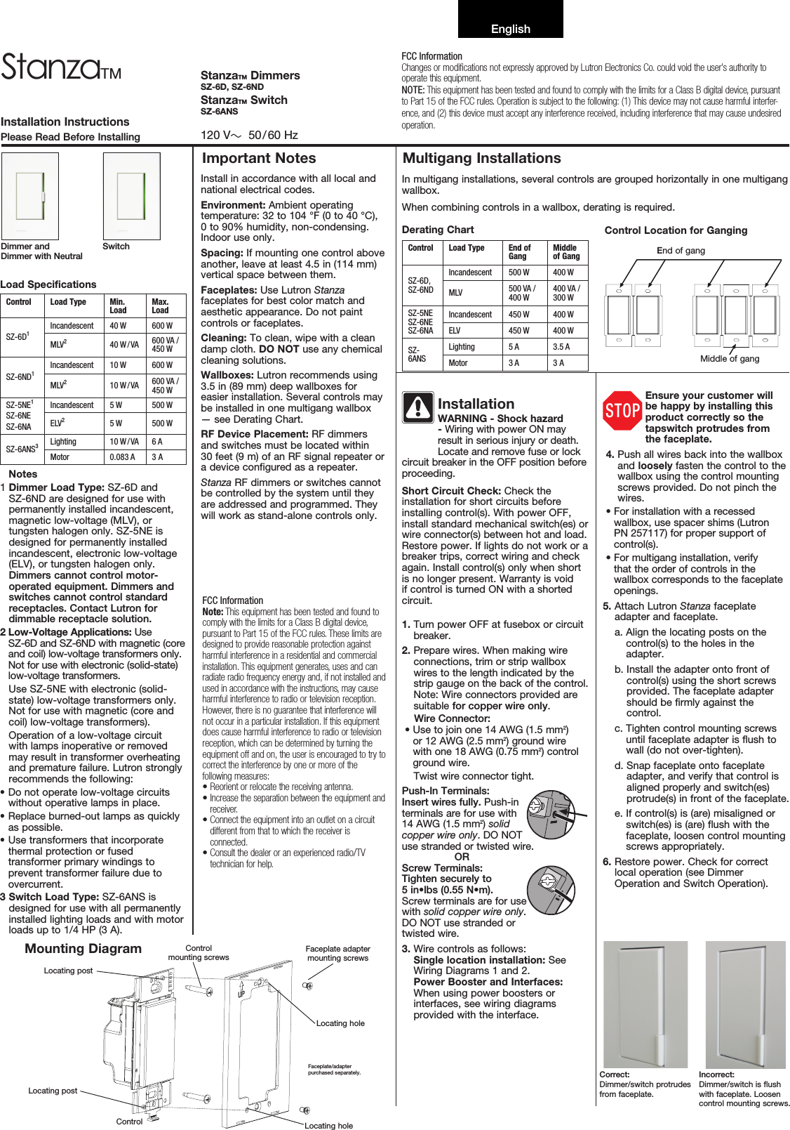
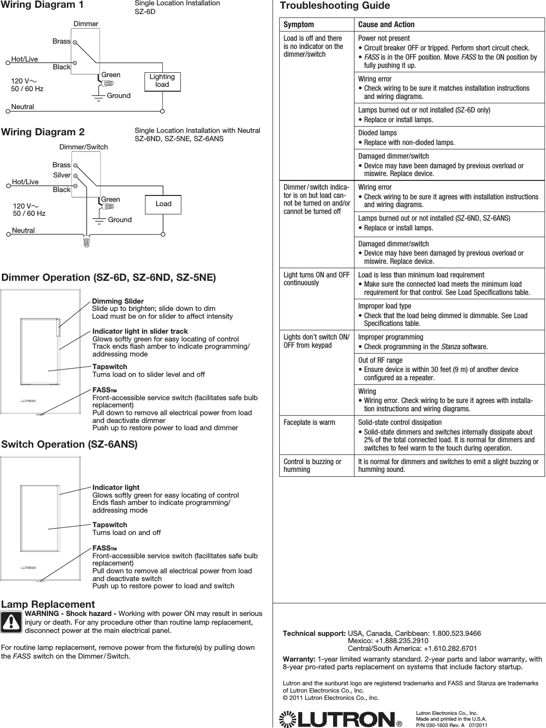
Lutron Electronics 0083 Wireless Dimmer Switch User Manual

Lutron Electronics Company Inc Wireless Dimmer Switch

User Manual

Load SpecificationsControl Load Type Min. LoadMax. LoadSZ-6D1Incandescent 40 W 600 WMLV240 W / VA 600 VA / 450 WSZ-6ND1Incandescent 10 W 600 WMLV210 W / VA 600 VA / 450 WSZ-5NE1SZ-6NESZ-6NAIncandescent 5 W 500 WELV25 W 500 WSZ-6ANS3Lighting 10 W / VA 6 AMotor 0.083 A 3 A   Notes1  Dimmer Load Type: SZ-6D and SZ-6ND are designed for use with permanently installed incandescent, magnetic low-voltage (MLV), or tungsten halogen only. SZ-5NE is designed for permanently installed incandescent, electronic low-voltage (ELV), or tungsten halogen only. Dimmers cannot control motor-operated equipment. Dimmers and switches cannot control standard receptacles. Contact Lutron for dimmable receptacle solution. 2  Low-Voltage Applications: Use  SZ-6D and SZ-6ND with magnetic (core and coil) low-voltage transformers only. Not for use with electronic (solid-state) low-voltage transformers.Use SZ-5NE with electronic (solid-state) low-voltage transformers only. Not for use with magnetic (core and coil) low-voltage transformers).Operation of a low-voltage circuit with lamps inoperative or removed may result in transformer overheating and premature failure. Lutron strongly recommends the following: •  Do not operate low-voltage circuits without operative lamps in place.•  Replace burned-out lamps as quickly as possible.•  Use transformers that incorporate thermal protection or fused transformer primary windings to prevent transformer failure due to overcurrent.3  Switch Load Type: SZ-6ANS is designed for use with all permanently installed lighting loads and with motor loads up to 1/4 HP (3 A).Install in accordance with all local and national electrical codes.Environment: Ambient operating temperature: 32 to 104 °F (0 to 40 °C),  0 to 90% humidity, non-condensing. Indoor use only.Spacing: If mounting one control above another, leave at least 4.5 in (114 mm) vertical space between them.Faceplates: Use Lutron Stanza faceplates for best color match and aesthetic appearance. Do not paint controls or faceplates.Cleaning: To clean, wipe with a clean damp cloth. DO NOT use any chemical cleaning solutions.Wallboxes: Lutron recommends using 3.5 in (89 mm) deep wallboxes for easier installation. Several controls may be installed in one multigang wallbox — see Derating Chart.RF Device Placement: RF dimmers and switches must be located within  30 feet (9 m) of an RF signal repeater or a device configured as a repeater.Stanza RF dimmers or switches cannot be controlled by the system until they are addressed and programmed. They will work as stand-alone controls only.Derating Chart Control Load Type End of GangMiddle of GangSZ-6D, SZ-6NDIncandescent 500 W 400 WMLV 500 VA / 400 W400 VA / 300 WSZ-5NESZ-6NESZ-6NAIncandescent 450 W 400 WELV 450 W 400 WSZ-6ANSLighting 5 A 3.5 AMotor 3 A 3 A InstallationWARNING - Shock hazard - Wiring with power ON may result in serious injury or death. Locate and remove fuse or lock circuit breaker in the OFF position before proceeding. Short Circuit Check: Check the installation for short circuits before installing control(s). With power OFF, install standard mechanical switch(es) or wire connector(s) between hot and load. Restore power. If lights do not work or a breaker trips, correct wiring and check again. Install control(s) only when short is no longer present. Warranty is void if control is turned ON with a shorted circuit.1.  Turn power OFF at fusebox or circuit breaker.2.  Prepare wires. When making wire connections, trim or strip wallbox wires to the length indicated by the strip gauge on the back of the control.  Note: Wire connectors provided are suitable for copper wire only.   Wire Connector:•  Use to join one 14 AWG (1.5 mm2) or 12 AWG (2.5 mm2) ground wire with one 18 AWG (0.75 mm2) control ground wire.Twist wire connector tight.  Push-In Terminals: Insert wires fully. Push-in terminals are for use with 14 AWG (1.5 mm2) solid copper wire only. DO NOT use stranded or twisted wire.  ORScrew Terminals:  Tighten securely to  5 in•lbs (0.55 N•m).  Screw terminals are for use with solid copper wire only. DO NOT use stranded or twisted wire.3.  Wire controls as follows: Single location installation: See Wiring Diagrams 1 and 2. Power Booster and Interfaces: When using power boosters or interfaces, see wiring diagrams provided with the interface.Ensure your customer will be happy by installing this product correctly so the tapswitch protrudes from  the faceplate. 4.  Push all wires back into the wallbox and loosely fasten the control to the wallbox using the control mounting screws provided. Do not pinch the wires.•  For installation with a recessed wallbox, use spacer shims (Lutron  PN 257117) for proper support of control(s).•  For multigang installation, verify that the order of controls in the wallbox corresponds to the faceplate openings.5.  Attach Lutron Stanza faceplate adapter and faceplate.   a.  Align the locating posts on the control(s) to the holes in the adapter.  b.  Install the adapter onto front of control(s) using the short screws provided. The faceplate adapter should be firmly against the control.  c.  Tighten control mounting screws until faceplate adapter is flush to wall (do not over-tighten).  d.  Snap faceplate onto faceplate adapter, and verify that control is aligned properly and switch(es) protrude(s) in front of the faceplate.  e.  If control(s) is (are) misaligned or switch(es) is (are) flush with the faceplate, loosen control mounting screws appropriately. 6.  Restore power. Check for correct local operation (see Dimmer Operation and Switch Operation).Installation InstructionsPlease Read Before InstallingStanzaTM StanzaTM DimmersSZ-6D, SZ-6NDStanzaTM SwitchSZ-6ANS120 V~  50 / 60 HzImportant Notes Multigang InstallationsDimmer and Dimmer with NeutralSwitchMiddle of gangEnd of gangControl Location for GangingFCC InformationChanges or modications not expressly approved by Lutron Electronics Co. could void the user’s authority to operate this equipment.NOTE: This equipment has been tested and found to comply with the limits for a Class B digital device, pursuant to Part 15 of the FCC rules. Operation is subject to the following: (1) This device may not cause harmful interfer-ence, and (2) this device must accept any interference received, including interference that may cause undesired operation.FCC InformationNote: This equipment has been tested and found to comply with the limits for a Class B digital device, pursuant to Part 15 of the FCC rules. These limits are designed to provide reasonable protection against harmful interference in a residential and commercial installation. This equipment generates, uses and can radiate radio frequency energy and, if not installed and used in accordance with the instructions, may cause harmful interference to radio or television reception. However, there is no guarantee that interference will not occur in a particular installation. If this equipment does cause harmful interference to radio or television reception, which can be determined by turning the equipment off and on, the user is encouraged to try to correct the interference by one or more of the following measures:•  Reorient or relocate the receiving antenna.•  Increase the separation between the equipment and receiver.•  Connect the equipment into an outlet on a circuit different from that to which the receiver is connected.•  Consult the dealer or an experienced radio/TV technician for help.Correct:  Dimmer/switch protrudes from faceplate.Incorrect:  Dimmer/switch is flush with faceplate. Loosen control mounting screws.STOPMounting DiagramControlFaceplate/adapter  purchased separately.Locating postFaceplate adapter mounting screwsControl  mounting screwsLocating postLocating holeLocating holeEnglishIn multigang installations, several controls are grouped horizontally in one multigang wallbox.When combining controls in a wallbox, derating is required.
Lutron Electronics Co., Inc.Made and print ed in the U.S.A.P/N 030-1603 Rev. A   07/2011Technical support:  USA, Canada, Caribbean: 1.800.523.9466 Mexico: +1.888.235.2910 Central/South America: +1.610.282.6701Warranty: 1-year limited warranty standard. 2-year parts and labor warranty, with 8-year pro-rated parts replacement on systems that include factory startup.Lutron and the sunburst logo are registered trademarks and FASS and Stanza are trademarks of Lutron Electronics Co., Inc.© 2011 Lutron Electronics Co., Inc.®Dimming SliderSlide up to brighten; slide down to dimLoad must be on for slider to affect intensitySwitch Operation (SZ-6ANS)Indicator light in slider trackGlows softly green for easy locating of controlTrack ends flash amber to indicate programming/addressing modeTapswitchTurns load on to slider level and offFASSTM  Front-accessible service switch (facilitates safe bulb replacement)Pull down to remove all electrical power from load and deactivate dimmerPush up to restore power to load and dimmerIndicator lightGlows softly green for easy locating of controlEnds flash amber to indicate programming/addressing modeTapswitchTurns load on and offFASSTM  Front-accessible service switch (facilitates safe bulb replacement)Pull down to remove all electrical power from load and deactivate switchPush up to restore power to load and switchLamp Replacement   WARNING - Shock hazard - Working with power ON may result in serious injury or death. For any procedure other than routine lamp replacement, disconnect power at the main electrical panel.   For routine lamp replacement, remove power from the fixture(s) by pulling down the FASS switch on the Dimmer / Switch.Troubleshooting GuideSymptom Cause and ActionLoad is off and there is no indicator on the dimmer/switchPower not present•  Circuit breaker OFF or tripped. Perform short circuit check.•  FASS is in the OFF position. Move FASS to the ON position by fully pushing it up.Wiring error•   Check wiring to be sure it matches installation instructions and wiring diagrams.Lamps burned out or not installed (SZ-6D only)•   Replace or install lamps.Dioded lamps•   Replace with non-dioded lamps.Damaged dimmer/switch•  Device may have been damaged by previous overload or miswire. Replace device.Dimmer / switch indica-tor is on but load can-not be turned on and/or cannot be turned offWiring error•   Check wiring to be sure it agrees with installation instructions and wiring diagrams.Lamps burned out or not installed (SZ-6ND, SZ-6ANS)•   Replace or install lamps.Damaged dimmer/switch•  Device may have been damaged by previous overload or miswire. Replace device.Light turns ON and OFF continuouslyLoad is less than minimum load requirement•  Make sure the connected load meets the minimum load requirement for that control. See Load Specifications table.Improper load type•  Check that the load being dimmed is dimmable. See Load Specifications table.Lights don’t switch ON/OFF from keypadImproper programming•  Check programming in the Stanza software.Out of RF range•  Ensure device is within 30 feet (9 m) of another device configured as a repeater.Wiring•   Wiring error. Check wiring to be sure it agrees with installa-tion instructions and wiring diagrams.Faceplate is warm Solid-state control dissipation•  Solid-state dimmers and switches internally dissipate about 2% of the total connected load. It is normal for dimmers and switches to feel warm to the touch during operation.Control is buzzing or hummingIt is normal for dimmers and switches to emit a slight buzzing or humming sound.Single Location InstallationSZ-6DWiring Diagram 1DimmerBrassBlackLighting loadHot/LiveNeutralGreenGround120 V~50 / 60 HzSingle Location Installation with NeutralSZ-6ND, SZ-5NE, SZ-6ANSDimmer/SwitchBrassBlackLoadHot/LiveNeutralGreenGround120 V~50 / 60 HzSilverDimmer Operation (SZ-6D, SZ-6ND, SZ-5NE)Wiring Diagram 2

Navigation menu