Lutron Electronics 0095 Roller Shade User Manual
Lutron Electronics Company Inc Roller Shade
user manual
Roller Shade
• Installation and Setup Guide—Please Read Before Installing and OperatingBattery Powered Window Shade with RF Wireless Remote Control
Lutron Electronics Co., Inc.
7200 Suter Road
Coopersburg, PA 18036-1299, U.S.A.
09/2013
P/N 045404 Rev. A
Lutron, O, Serena and Pico are registered trademarks of Lutron Electronics Co., Inc.
Equal depth
both sides
A
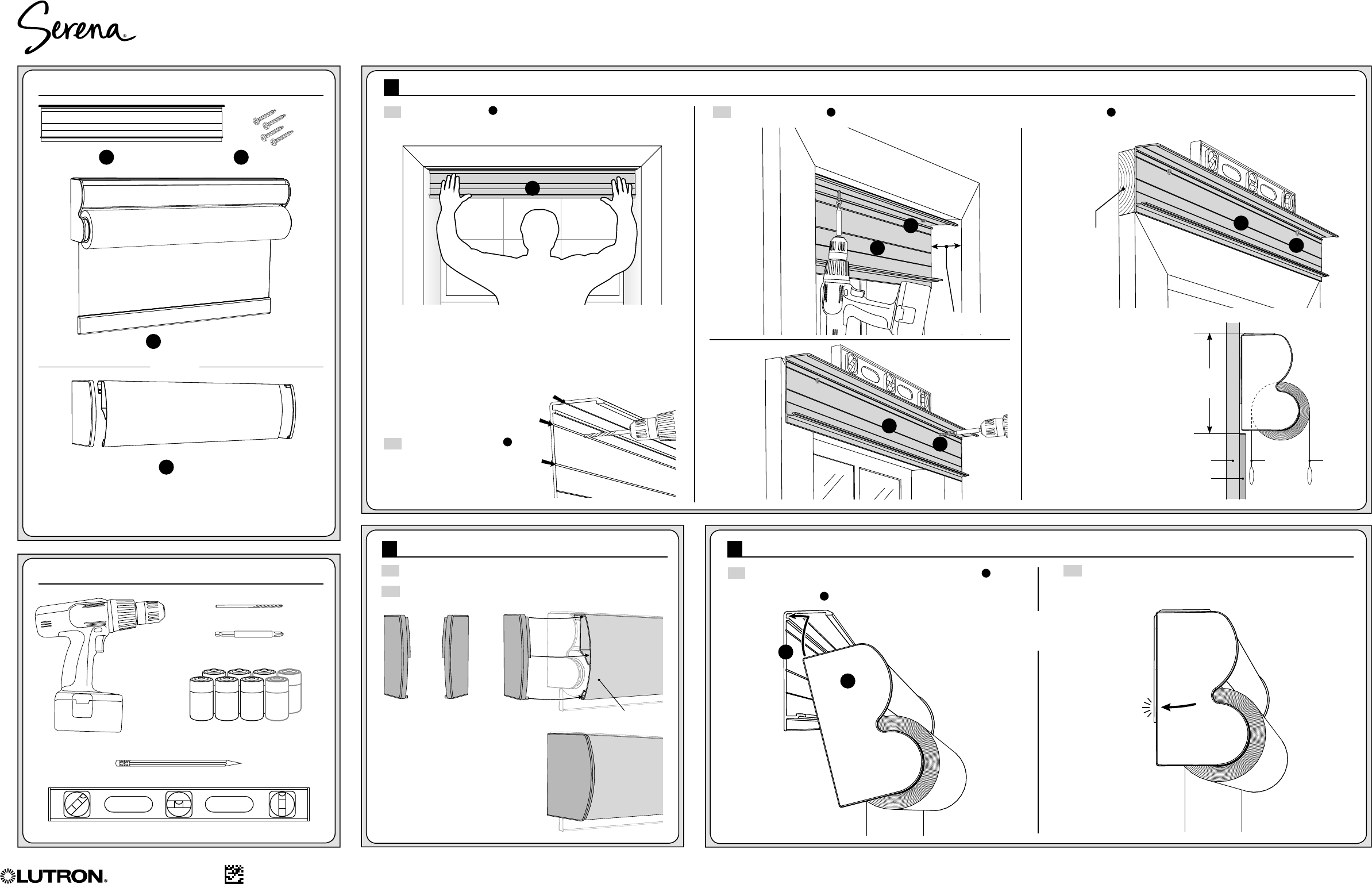
1 Mounting the shade rail:
3 Hanging the shade:
2 Installing the end caps on optional fascia:
2.1 Press-fit an end cap on the open end of the fascia as shown.
2.2 Repeat on the other end.
3.1 Facing the window, tilt the top of the shade assembly C
away from you and insert its top rear edge into the channel
in the shade rail A.
3.2 Push the bottom of the shade toward the window and lock it
into the shade rail with a “click.”
1.1 Hold the shade rail A up to the mounting surface. Approximate
its final position and use a pencil to mark mounting screw
locations on the shade rail.*
1.2 Pre-drill the shade rail A
at the pencil marks.
1.3 Fasten the shade rail A, to the mounting surface using the mounting screws provided B or other appropriate fasteners.
NOTE: The shade rail features
grooves to help stabilize the point
of your drill bit.
**NOTE: Depending on the size
of your shade and the depth of
your trim, or the roll direction of
your shade, you may be able
to mount the shade directly to
the wall above the trim without
additional spacing.
In this arrangement, the top
of the shade rail must be a
minimum of 4
1
/2 in (114 mm)
above the top of the trim.
Optional fascia/end caps
not shown
NOTE: If your shade was ordered with optional fascia, the fascia
will be factory-attached and wrapped with the shade. Leave the
wrapping in place during installation for added stability, then remove
the wrap before installing batteries.
*To ensure the shade rail is properly mounted, we rcommend:
a. Install mounting screws 6-12 in (152-305 mm) from each end of the
shade rail.
b. Locate the mounting screws so that they drive into studs or solid
trim. For other surfaces, use appropriate expansion anchors, toggle
bolts, or other fasteners, (not included).
c. Verify that the mounted
shade rail is level and
parallel to the window
opening.
#2 Phillips Driver Bit
1/8 in (3.2 mm) Drill Bit
Pencil
Level
D-Cell Alkaline Batteries
(6 or 8 depending on shade size)Power Drill
OPTIONAL
(1) Shade Rail
AMounting Screws
B
Serena® Roller
Shade Assembly
C
(1) Fascia with end caps
D
CLICK!
CLICK!
A
B
A
C
A
Outside
Mount
on Trim
Outside Mount
above Trim
A
Spacer blocks
or board
(not included)
securely
mounted to wall
above trim**
GROOVES
Worldwide Headquarters | USA
Lutron Electronics Co., Inc. 7200 Suter Road, Coopersburg, PA 18036-1299 USA
TEL: 1.610.282.3800 • FAX: 1.610.282.3090
Technical Support: 1.800.523.9466 • Toll Free: 1.888.LUTRON1
Email: shadinginfo@lutron.com • Online: www.lutron.com/shadingsolutions
Europe Headquarters | United Kingdom
Lutron EA Ltd. 6 Sovereign Close, London, E1W3JF, UK
TEL: +44.(0)20.7702.0657 • FAX: +44.(0)20.7480.6899
Technical Support: +44.(0)20.7680.4481
FREEPHONE: 0800.282.107
Inside
Mount
B
B
Included in the box:
Other items you’ll need:
End Caps
Left end cap
shown
Left end cap
installed
Fascia
Left Right
NOTE: If your shade will be inside-
mounted, both end caps must be
installed and fully seated before
proceeding to the next step.
4.5 in
(114 m m)
min.
Wall Regular
roll
Reverse
roll
Trim
Lutron Electronics Co., Inc.
7200 Suter Road
Coopersburg, PA 18036-1299, U.S.A.
09/2013
P/N 045404 Rev. A
Lutron, O, Serena and Pico are registered trademarks of Lutron Electronics Co., Inc.
Serena® Roller Shade Installation and Setup Guide Page 2
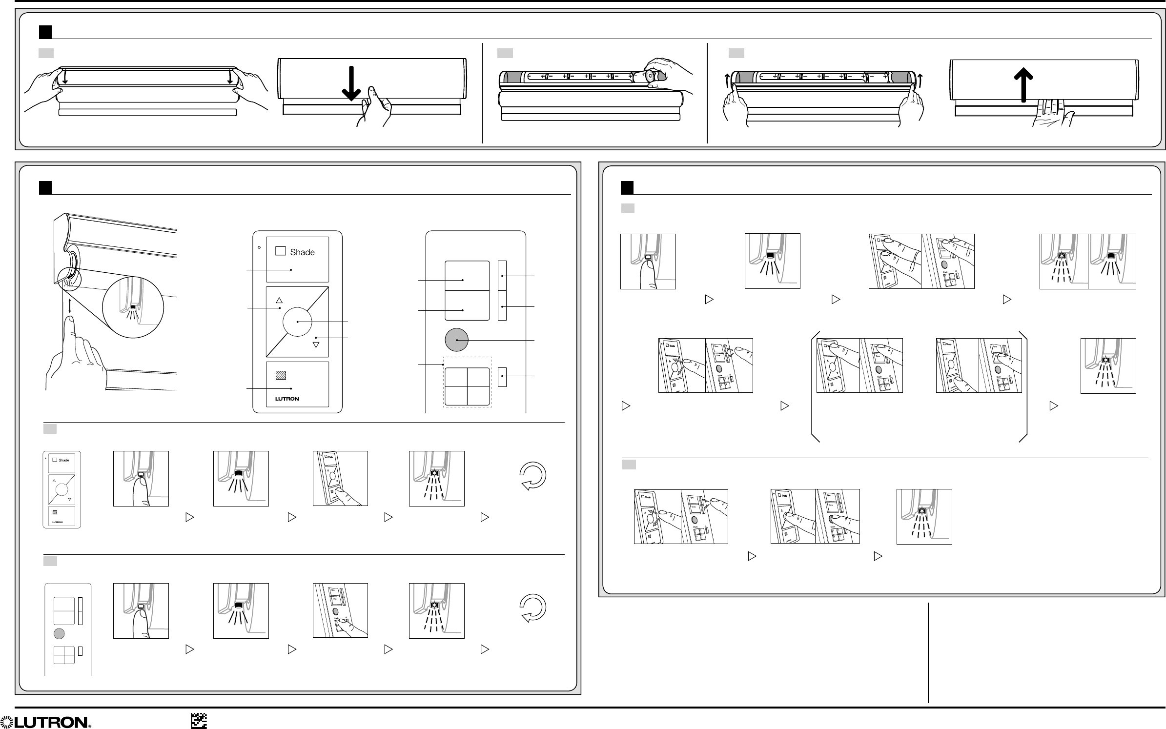
6 Adjusting shade limits and presets (OPTIONAL):
6.1 Adjust Upper or Lower Limit (OPTIONAL)
The shade’s upper and lower limits are pre-programmed based on the window dimensions and mounting option. If adjustment is needed, follow these steps:
Serena® 4-Group RF remote control
Shade Button
with LED
Open
Close
Shade All
1 2
3 4
Open
Close
Shade All
1 2
3 4
5 Assigning a remote control:
Pico® wireless control
Exposed headrail: rotate the top section forward. Exposed headrail: rotate the top section back to the closed position
Open
Open
Preset
Preset
Close
Close
Shade
Groups
Lower
Lower
All Shade
Groups
Raise
Raise
5.1 Assign a Pico® Wireless Control
Press and hold
the Close button.
Tap the Shade
Button.
Tap the Shade
Button.
The Shade Button lights.
The Shade Button lights.
The Shade
Button flashes.
Assignment is
complete.
The Shade
Button flashes.
Assignment is
complete.
Repeat for
additional
shade/control
assignments.
Repeat for
additional
shade/control
assignments.
5.2 Assign a Serena® 4-Group RF Remote Control
Choose a Shade
Group button.
Press and hold.
The Shade Button flashes,
then stays on.
Compatible Remote Controls (sold separately)
Press and hold the Open
and Raise Buttons.
Press and hold the
Preset Button.
Use the Raise and Lower Buttons
to position the shade at the
preferred upper or lower limit.
6.2 Set Preset Level (OPTIONAL)
The preset level is factory programmed to 50% open/closed.
Tap the Shade
Button.
The Shade Button lights.
The Shade
Button flashes.
Limit set is
complete.
The Shade
Button flashes.
Preset level
is set.
SET UPPER LIMIT
With the shade at the
preferred upper limit, press
and hold the Open Button.
OR SET LOWER LIMIT
With the shade at the
preferred lower limit, press
and hold the Close Button.
Use the Raise and Lower Buttons
to position the shade at the
desired preset level.
4 Installing the batteries:
4.1 Open the battery holder at the top of the shade. 4.2 Insert new D-cell alkaline batteries. 4.3 Return the battery holder to the closed position.
With optional fascia: pull straight down on the fascia. With optional fascia: gently push straight up on the fascia.A label on the battery holder shows quanity and orientation.
FCC Information
Models: SYC-J-EDU-R2, QSFC-J-EDU-R2
This equipment has been tested and found to comply with the limits for a
Class B digital device, pursuant to part 15 of the FCC rules. These limits are
designed to provide reasonable protection against harmful interference in
a residential installation. This equipment generates, uses and can radiate
radio frequency energy and, if not installed and used in accordance with
the instructions, may cause harmful interference to radio and television
reception, which can be determined by turning the equipment off and
on. The user is encouraged to try to correct the interference by one or
more of the following measures:
• Reorient or relocate the receiving antenna.
• Increase the separation between the equipment and receiver.
• Connect the equipment into an outlet on a circuit different from that to
which the receiver is connected.
• Consult the dealer or an experienced radio/TV technician for help.
Worldwide Headquarters | USA
Lutron Electronics Co., Inc. 7200 Suter Road, Coopersburg, PA 18036-1299 USA
TEL: 1.610.282.3800 • FAX: 1.610.282.3090
Technical Support: 1.800.523.9466 • Toll Free: 1.888.LUTRON1
Email: shadinginfo@lutron.com • Online: www.lutron.com/shadingsolutions
Europe Headquarters | United Kingdom
Lutron EA Ltd. 6 Sovereign Close, London, E1W3JF, UK
TEL: +44.(0)20.7702.0657 • FAX: +44.(0)20.7480.6899
Technical Support: +44.(0)20.7680.4481
FREEPHONE: 0800.282.107
Caution: Changes or modifications not expressly approved by Lutron
Electronics Co. could void the user’s authority to operate this equipment.
This device complies with Part 15 of the FCC Rules. Operation is subject
to the following two conditions:
(1) This device may not cause harmful interference, and
(2) This device must accept any interference received, including interference that may
cause undesired operation. This Class B digital apparatus complies
with Canadian ICES-003.
IC Information
This device complies with Industry Canada licence-exempt RSS standard(s).
Operation is subject tot he following two conditions:
(1) This device may not cause harmful interference, and
(2) This device must accept any interference received, including interference
that may cause undesired operation of the device.
For complete warranty information, please see: www.serenashades.com/warranty