Lutron Electronics 0114 Wireless Dimmer Switch User Manual 0301815a
Lutron Electronics Company Inc Wireless Dimmer Switch 0301815a
Contents
- 1. 0301815a Instruction sheet
- 2. Regulatory statements
0301815a Instruction sheet
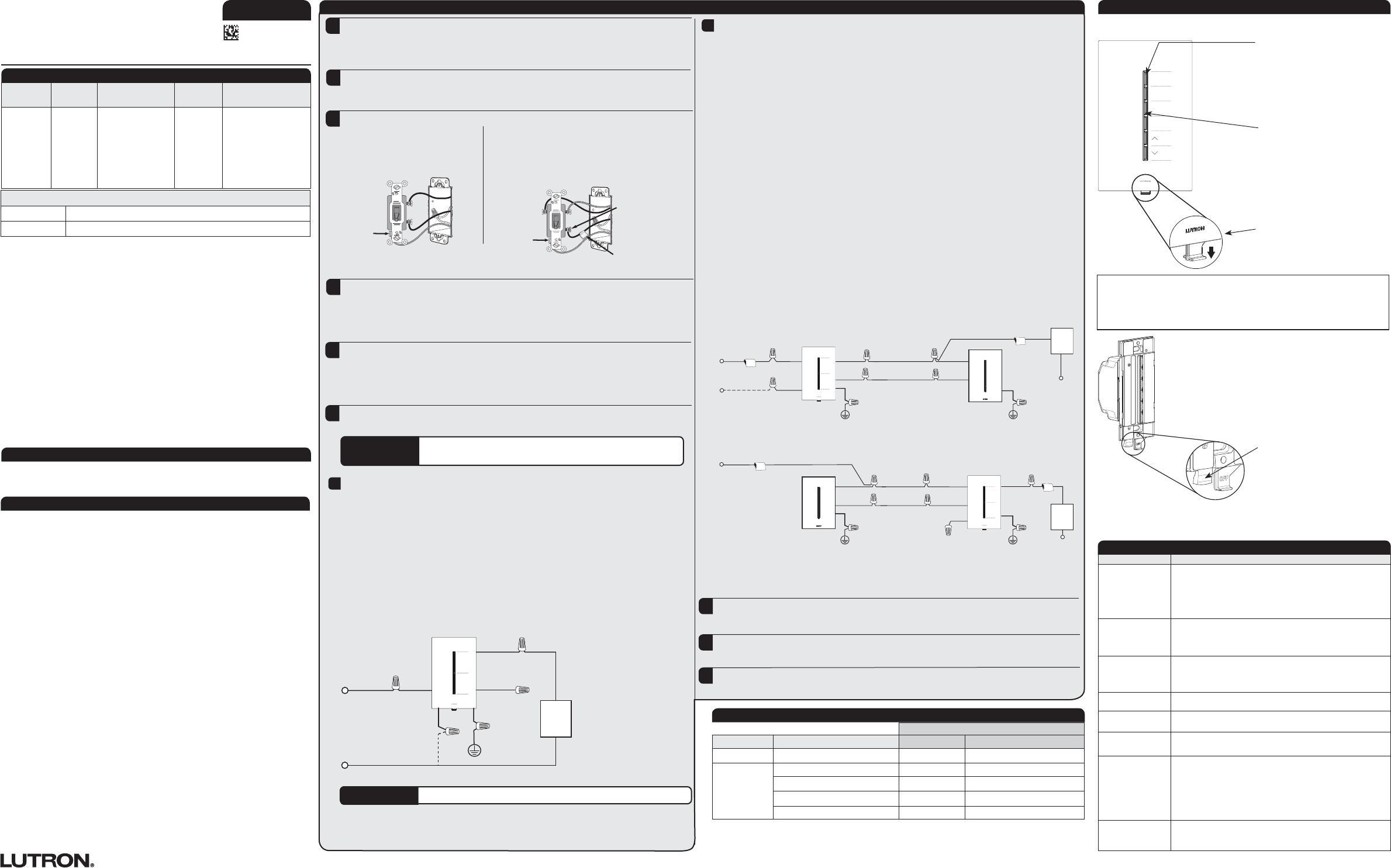
Nightlight
Day
Evening
Off
Installation Instructions
Please Read Before Installing
P/N 0301815
Rev A
GRAFIK TTM
Lutron Electronics Co., Inc.
7200 Suter Road, Coopersburg, PA 18036-1299 USA
120 V~ 50 / 60 Hz
6a
1 GRAFIK TTM -GH2B, -GH4B, -GH5B, and -GH6B models can control power boosters / load interfaces if
neutral is used. See Lutron® P / N 369971 and 369985, Compatible Power Boosters and Load Interfaces.
2 RRT- models are RadioRA® 2 compatible and HQRT- models are HomeWorks® QS compatible.
3 Not for use with receptacles or appliances (e.g., garbage disposals). See Lutron® Application Note #109 for
compatibility with dimmed receptacles.
4 Magnetic Low-Voltage Applications: Use with halogen-based lamps only.
5 UL® listed for use with dimmable ELV transformers, but not recommended because Lutron does not do
system performance testing.
6 Operation of a low-voltage circuit with lamps inoperative or removed may result in transformer overheating
and premature failure. Lutron strongly recommends the following:
• Do not operate low-voltage circuits without operative lamps in place.
• Replace burned-out lamps as soon as possible.
• Use transformers that incorporate thermal protection or fused transformer primary windings to prevent
transformer failure due to overcurrent.
7 When using the hybrid keypad to control MLV halogen-based xtures, the maximum lamp wattage is
determined by the efciency of the transformer, with 70%–85% as typical. For actual transformer efciency,
contact either the xture or transformer manufacturer. The total VA rating of the transformer(s) shall not
exceed the VA rating of the hybrid keypad.
8 Ten (10) driver maximum.
9 Includes Lutron® Hi-lume® 1% 2-wire LED drivers, Mark XTM, Tu-Wire®, and POWERSENSE®.
10 Neutral is required for Mark XTM, Tu-Wire®, and POWERSENSE®.
English
Single-pole – Switch will be replaced by a GRAFIK TTM hybrid keypad.
Connect the Green ground wire on the hybrid keypad to the Green
or bare
ground wire in
the wallbox (See Important Notes, number
3).
Connect the
Black
wire on the
hybrid keypad
to one of the wires removed from the switch. If
you had taped together two wires (see step4), connect both wires to the
Black
wire on the
hybrid keypad
and remove the tape.
Connect the Red wire on the hybrid keypad to the other wire removed from the switch.
Connect the White wire on the hybrid keypad to the neutral wire in the wallbox
(See Important Notes, number 7).
The switch may have two wires attached to the same screw. Tape these two wires together
before disconnecting. Proceed to disconnect the wires from the switch.
Remove wallplate from the GRAFIK TTM hybrid keypad and any companion device but leave
wallplate adapter connected.
Install GRAFIK TTM control.
Identify switch type.
Single-pole – The switch will have
insulated wires connected to two
screws of the same color plus a green
ground screw.
Multi-location – 3-way switches will have insulated
wires connected to three screws plus a green
ground screw. One of the wires is connected to
a screw of a different color (not green) or labeled
COMMON. Tag this wire.
Ground
Remove wallplate and the switch mounting screws. Leaving all wires attached, carefully pull
the switch out from the wall.
1Turn OFF power at circuit breaker.
IMPORTANT NOTICE: FASSTM – Front Accessible Service Switch
To replace lamp(s), power may be conveniently removed by pulling the FASSTM down on the hybrid
keypad. After replacing lamp(s), push the FASSTM back up fully to restore power to the hybrid
keypad. For any procedure, other than routine lamp replacement, power must be turned OFF
at the main electrical panel.
IMPORTANT Wire connectors provided are for copper wires only. For aluminum
wires, consult an electrician.
Hybrid
Keypad
1,2,3
LED Incandescent /
Halogen
MLV
4,5,6,7
Halogen
Dimmable Electronic
Ballast or Driver
8,9,10
RRT-GH2B
RRT-GH4B
RRT-GH5B
RRT-GH6B
HQRT-GH2B
HQRT-GH4B
HQRT-GH5B
HQRT-GH6B
250 W
600 W (Not ganged)
500 W (End of gang)
400
W
(Middle of gang)
400 VA
(300 W)
3.3 A
(400 VA)
Companion Device
Connect the Green wire on the companion device to the Green or
bare
ground wire in the wallbox
(See Important Notes, number
3).
Connect the Red wire on the companion device to the tagged wire and to the same color wire
connected to the Red wire on the hybrid keypad .
Connect the Blue wire on the companion device to the remaining wire.
Installation
2
Operation
3
4
5
6
FASS
TM
:
Front Accessible Service Switch
Note: FASS
TM
is not available on
companion devices.
Customer Assistance: www.lutron.com U.S.A. | Canada | Caribbean: 1.844.LUTRON1 | Mexico: +1.888.235.2910 | Others: +1.610.282.3800 • For warranty details, please visit: www.lutron.com/TechnicalDocumentLibrary/warranty.pdf | For FCC/IC information, please visit: www.lutron.com/fcc-ic
Lutron, C•L, Hi-lume, and Tu-Wire are registered trademarks and FASS, and GRAFIK T are trademarks of Lutron Electronics Co., Inc. NEC is a registered trademark of the National Fire Protection Association, Quincy, Massachusetts. POWERSENSE is a registered trademark of Osram Sylvania, Inc. Mark X is a registered trademark of Philips Lighting Electronics N.A., Inc. © 2014-2015 Lutron Electronics Co., Inc.
Ground
Different-colored
screw
Tag/Common
Companion devices
RT-GRDW For use with RRT– hybrid keypads, dimmers and switches (0.1 A)
HQT-GRDW For use with HQRT– hybrid keypads, dimmers and switches (0.1 A)
! WARNING! Shock Hazard. May result in serious injury or death. Turn off power at
circuit breaker before installing the unit.
Symptom
Possible Solutions
1. Lamp and light bar
LEDs do not turn on.
• Push FASSTM up to restore power.
• Turn ON breaker.
• Replace burned out lamp(s).
• Check hybrid keypad wiring (See Installation).
• Cycle power to unit by pulling the FASSTM down and back up to fully
restore power. If unit beeps see Symptom 2.
2. Unit beeps after
power cycle.
• Check wiring. If neutral wire is connected, ensure that the Black wire is
connected to Live and the Red wire is connected to Load.
• Check wiring. Ensure that the Blue and Red wires are connected as
specified in Installation.
3. Lamps turn On and
hybrid keypad works
but companion device
does not work.
• Ensure that the wire connected to the Blue (or Red) wire on the hybrid
keypad is the same as that connected to the Blue (or Red) wire on the
companion device (See Installation Step 6b).
4. Lamps repeatedly
turn On and Off. • See Minimum Load and ensure the acceptable minimum load is met.
5. Lamps icker or exhibit
poor dimming range.
• Set low-end trim. See Installation Step 9 for details.
• See Recommended LEDs.
6. Wallplate is warm.
• Solid-state hybrid keypads internally dissipate about 1% of the total
connected load. It is normal for hybrid keypads to feel warm to the touch
during operation.
8. Lamps don’t turn
On / Off from a
keypad.
• Improper programming. Programming must be done through the system
software.
• Out of RF range. Reposition to be within 30 ft (9 m) of an RF signal repeater.
• Wires shorted. Make sure the blue terminal is not grounded or shorted to
any other wires.
• Wiring error. Ensure wiring matches installation instructions and appropriate
wiring diagram.
9. All LEDs on the hybrid
keypad ash when
any button is pressed.
• The hybrid keypad is in factory settings mode and has not been
congured to work in a system. Follow the steps in the System Setup
Guide to program.
Troubleshooting
Hybrid Keypad Line-Side (with or without neutral wire)
1
IMPORTANT Cut the blue wire at the insulation and cap with the yellow connector.
Multi-location – Lamps can be controlled from multiple locations.
One location will be replaced by a GRAFIK TTM hybrid keypad and the other location(s) by a
GRAFIK TTM companion device. If the neutral wire is not being used, the hybrid keypad can be
wired on the line-side or the load-side. If using the neutral wire, the hybrid keypad must be wired
on the line-side.
6b
Hybrid Keypad
Connect the Green ground wire on the
hybrid keypad
to the Green or bare ground wire in the
wallbox (
See Important Notes, number
3
).
Connect the Black wire on the hybrid keypad to the tagged wire removed from the switch.
Connect the Red wire on the hybrid keypad to one of the remaining wires.
Connect the Blue wire on the hybrid keypad to the remaining wire.
Connect the White wire on the hybrid keypad to the neutral wire in the wallbox
(See Important Notes, number
7).
120 V~
60 Hz
Black
Ground
Red
Blue
Green
Neutral
Line / Hot
Load
White
Connect if using
neutral wire
Uncommissioned Behavior
• Top button toggles local load On/
Off
•All other buttons utter to indicate
uncommissioned status
Flexible Control
• Press to activate a scene or zone
• Buttons provide scene / zone status
• Buttons are fully programmable
1. CAUTION: To avoid overheating and possible damage to other equipment, do not use
hybrid keypads to control receptacles or motor-operated appliances.
2. Install in accordance with all national and local electrical codes.
3. When no “grounding means” exist in wallbox, the NEC® allows control without a grounding
connection to be installed as a replacement if 1) a non-metallic, noncombustible faceplate
is used with nonmetallic attachment screws or 2) the circuit is protected by a ground fault
circuit interrupter (GFCI). For this type of installation, cap or remove the green ground wire
on the hybrid keypad, and only use a Lutron® GRAFIK TTM wallplate.
4. GRAFIK TTM controls are not compatible with standard 3-way switches. Use only with GRAFIK
TTM companion devices.
5. GRAFIK TTM Companion devices cannot be used individually but must be used in conjunction
with a GRAFIK TTM hybrid keypad in a multi-location application.
6. In any multi-location circuit, use only one GRAFIK TTM hybrid keypad with up to four
GRAFIKTTM companion devices.
7. Neutral wire connection is optional for GRAFIK TTM hybrid keypad; however, the best
dimming performance will be obtained when the neutral wire is connected. Always cap the
white wire if a neutral wire is not present in wallbox.
8. Return to Factory Settings (Note: Returning a control to the factory settings will remove it
from the system and erase all programming).
Step 1: Triple tap any button on a control. DO NOT release after the third tap.
Step 2: Keep the button pressed on the third tap (for approximately 3 seconds) until the
LEDs on the control start to scroll up and down quickly.
Step 3: Release the button and immediately triple tap the button again. The LEDs on the
control will scroll up and down slowly. Factory settings have been restored.
Important Notes
If dimming LED bulbs, they must be Lutron® compatible! For current compatibility and
performance information visit www.lutron.com/LED.
Recommended LEDs
Load Type
Application Number of Companion Devices LED
1, 2 Incandescent / Halogen 3
Single-pole 0 3 LED lamps 80 W
Multi-location
1 4 LED lamps 120 W
2 5 LED lamps 160 W
3 6 LED lamps 200 W
4 7 LED lamps 240 W
Minimum Load:
1 See Recommended LEDs.
2 If using neutral wire, the minimum load required is one LED lamp or Lutron® Hi-lume® 1% 2-wire LED driver.
3 If using neutral wire, the minimum incandescent/halogen load required is 5 W.
Hybrid Keypad Load-Side (without neutral wire only)
1
Live
Ground
Black
Red
Blue
White
Green
Blue
Red
Green
Ground
Load
Neutral
2
Tag/Common
Hybrid Keypad
Companion device(s)
Tag/Common
Line / Hot
Neutral
1
(Connect if using
neutral wire)
Black Red
Blue
White
Blue
Red
Green
Green
Ground
Ground
Load
2
Neutral
Hybrid Keypad Companion device(s)
Tag/Common
Tag/Common
1 Neutral wire connection is optional for GRAFIK TTM hybrid keypads; however, the best dimming performance will be obtained
when neutral wire is connected.
2 The companion device is wired differently than a standard 3-way switch. Both the Red wire and the tagged wire are
connected to the same traveler wire.
Turn ON power at circuit breaker.
8
If desired, consider adjusting low-end and high-end trim by using the RadioRA® 2 or
HomeWorks® QS GUI software.
9
Carefully push wires into the wallbox. Install controls and snap on wallplate.
7
Model Numbers
DBM:
Dynamic Backlight Management Sensor
Note: DBM should be mounted with an
unobstructed, clear view of the floor. DO
NOT paint or plaster over sensor.