Luxul Wireless PWFC2 PRO-WAV Wi-Fi Range Extender System User Manual

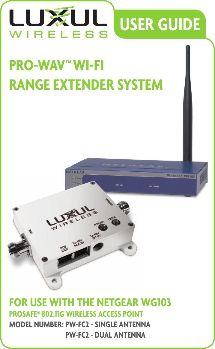
Luxul Wireless PRO-WAV Wi-Fi Range Extender System

user manual

USER GUidEPRo-WAV™ Wi-Fi  RAnGE ExtEndER SYStEMFoR USE With thE nEtGEAR WG103 PRoSAFE® 802.11G WiRElESS AccESS PointModEl nUMbER:  PW-Fc2 - SinGlE AntEnnA PW-Fc2 - dUAl AntEnnA
PRO-WAV WI-FI RANGE EXTENDER SYSTEM MODEL NUMBER: PW-FC2INSTALLATION GUIDE© 2010 by Luxul Wireless, Inc. All rights reserved.No part of this publication may be modified or adapted in any way, for any purposes without permission in writing from Luxul Wireless, Inc. (Luxul). The material in this manual is subject to change without notice. Luxul reserves the right to make changes to any product to improve reliability, function, or design. No license is granted, either expressly or by implication or otherwise under any Luxul Wireless, Inc., intellectual property rights. An implied license only exists for equipment, circuits and subsystems contained in Luxul products. Antenna for broadband wireless communications This product is covered by one or more U.S. and foreign patents.  Patents: 7,379,717 6,606,075, 6,373,448, other patents pendingPRO-WAV WI-FI RANGE EXTENDER SYSTEM MODEL NUMBER: PW-FC2FCC ID: W59PWFC2 IC: 8584A-PWFC2NETGEAR WIRELESS ACCESS POINT MODEL NUMBER: WG103 FCC ID: PY308400097 IC: 4054A-08400097Luxul Wireless, Inc. 357 South 670 West, Suite 160 Lindon, UT 84042 www.luxulwireless.com
ShocK-WAV SiGnAl booStER USER GUidE1CONTENTS1 - INTRODUCTION . . . . . . . . . . . . . . . . . . . . . . . . . . . . . . . . . . . . . . . . . . . . . . . . . . . . . . . . . . . . 21.1 Document Conventions ................................................................21.2 Warnings..............................................................................21.3 Site Preparation  .......................................................................31.4 Professional Installation Considerations .................................................32 - SPECIFICATIONS ............................................................42.1 SHOCK-WAV™ WI-FI SIGNAL BOOSTER SPECIFICATIONS .................................42.2 X-WAV™ FLAT PANEL ANTENNA SPECIFICATIONS .......................................43 - GETTING STARTED ..........................................................53.1 Precautions  ...........................................................................53.2 Package Contents .....................................................................53.3 Additional Items Required .............................................................64 - INSTALLATION PROCEDURES................................................64.1 Removing the Stock Antenna from the Netgear WG103 ..................................64.1  Connecting the PW-FC2 - Single Antenna to the Netgear WG103 .........................74.2  Connecting the PW-FC2 - DUAL Antenna to the Netgear WG103 .........................74.3 Connecting Direct Power and Data Source cables  .......................................84.4 Connecting POE Power and Data Source cables .........................................84.5 Optional POE Injector.................................................................95 - ANTENNA PLACEMENT .....................................................95.1 Antenna Deployment ..................................................................96 - REGULATORY COMPLIANCE ................................................116.1 Health and Safety Recommendations ..................................................116.2 RF Exposure Guidelines............................................................... 116.3 Radio Frequency Interference Requirements—FCC  .....................................126.4 Radio Transmitters (Part 15) ...........................................................136.5 Industry Canada ( RSS-Gen Issue 2) ....................................................137 - SALES AND SUPPORT CONTACTS............................................13
21 - INTRODUCTIONThe Luxul Wireless Pro-WAV Wi-Fi Range Extender System is designed to complement and enhance the performance of the Netgear WG103 Wireless Access Point (WAP). When com-bined with the WG103 and X-WAV XW-24-FP7 Flat Panel Antenna, it delivers up to the maximum approved transmit power, resulting in a farther reaching and higher performing network. Luxul Wireless Pro-WAV Wi-Fi Range Extender System feature patented RF technology that dynamically optimizes output strength and provides the cleanest, most consistent signal  amplification available for Wi-Fi networks. Designed for bidirectional signal amplification, Shock-WAV Wi-Fi Signal Boosters utilize patented Digital Automatic Gain Control (D-AGC) tech-nology that actively monitors the incoming signal from each packet and makes adjustments so that the output signal maintains constant power levels, ensuring the cleanest and most consistent RF signal possible.1.1 DOCUMENT CONVENTIONSThe following graphical alerts are used in this document to indicate notable situations:    NOTE:  Tips, hints, or special requirements that you should take note of.    CAUTION:   Care is required. Disregarding a caution can result in data loss or  equipment malfunction.    WARNING!:   Indicates a condition or procedure that could result in personal injury  or equipment damage.1.2 WARNINGS•  Read all installation instructions and site survey reports, and verify correct equipment installation before connecting the Shock-WAV Wi-Fi Signal Booster or WG103 to its power source.•  Remove jewelry and watches before installing this equipment.•  Verify that the unit is grounded before connecting it to the power source.•  Verify that any device connected to this unit is properly wired and grounded.•  Connect all power cords to a properly wired and grounded electrical circuit.•  Verify that the electrical circuits have appropriate overload protection.•  Attach only approved power cords to the device.
ShocK-WAV SiGnAl booStER USER GUidE3•  Verify that the power connector and socket are accessible at all times during the  operation of the equipment.•  Do not work with power circuits in dimly lit spaces.•  Do not install this equipment or work with its power circuits during thunderstorms or  other weather conditions that could cause a power surge.•  Verify there is adequate ventilation around the device, and that ambient temperatures meet equipment operation specifications.•  Products outside the approved configurations may be in violation of Part 15 of the FCC Rules.1.3 SITE PREPARATION•  Consult your site survey and network analysis reports to determine  specific equipment placement, power drops, and so on.•  Assign installation responsibility to the appropriate personnel.•  Identify and document where all installed components are located.•  Provide a sufficient number of power drops for your equipment.•  Ensure adequate, dust-free ventilation to all installed equipment.•  Identify and prepare Ethernet and console port connections.•  Verify that cable lengths are within the maximum allowable distances  for optimal and certified signal transmission.1.4 PROFESSIONAL INSTALLATION CONSIDERATIONS    CAUTION:   Operation of the signal booster without regulatory approval is illegal The Luxul Wireless Pro-WAV Wi-Fi Range Extender System is required to be professionally installed. The following components are approved for use in the system.•  Luxul PW-FC2 Wi-Fi Signal Booster•  Luxul Wireless X-WAV XW-24-FP7 Flat Panel Antenna•  Netgear WG103 Wireless Access Point•  Netgear Omni antenna included with WG103 access pointThe output power of the amplifier is set and tested during manufacturing. There are no user modifiable parameters in the amplifier. The Luxul Shock-WAV Wi-Fi Signal Booster system incorporates a Digital AGC (D-AGC) that ensures a consistent and approved output power.Please reference section 4 for installation instructions.
42 - SPECIFICATIONS2.1 SHOCK-WAV™ WI-FI SIGNAL BOOSTER SPECIFICATIONSOperating Range  2400 - 2483 MHz Transmit Power  1WattTransmit Gain  20dB Typical (under D-AGC Control)Receive Gain  17dB Typical TX Input Power  +8dBm to +24dBmNoise Figure  3.5dB Typical LED Indicators TX\RX Red for Transmit, Green for ReceivePower Consumption 400mW (RX) 5W (TX) MaxPower Options  Power Over Ethernet (POE) or AC-DC adapterOperating Voltage 24 to 57VDC Operating Temp  -4 F to +122F (-20c - +50c)Dimensions  W: 4” (101.6mm) L: 5.16” (131mm) H: 1.13” (28.7mm)Enclosure  Indoor, AluminumRF Connectors  Two (2) Type N FemaleWeight  0.7lbs. (317.5g)2.2 X-WAV™ FLAT PANEL ANTENNA SPECIFICATIONSFrequency Range 2400 - 2500MHzGain 7dBi CP GainPolarization Clear-WAV  Right Hand CircularConnector N FemaleAzimuth Beam Width 70 degreesElevation Beam Width 70 degreesVSWR < 1.5:1F/B Ratio 23dBImpedence 50 OhmDimensions W: 4.25” (107.95mm), L: 4.25” (107.95mm) , H: 1.6” (40.64mm)Weight 4.5 oz (127.5g)
ShocK-WAV SiGnAl booStER USER GUidE53 - GETTING STARTED3.1 PRECAUTIONSBefore installing the Shock-WAV Wi-Fi Signal Booster and WG103 verify the following:•  Do not install in wet or dusty areas without additional protection. Contact  a Luxul Wireless representative for more information.•  Verify the environment has a continuous temperature range between -4 F to +122F (-20c - +50c).3.2 PACKAGE CONTENTSThe Luxul Wireless Pro-WAV Wi-Fi Range Extender System consists of the following:One-Shock-WAV Wi-Fi Signal Booster•  PW-FC2 - Single Antenna: One-XW-24-FP7 - 7dBi High Gain 2.4GHz•  PW-FC2 - Dual Antenna: Two-XW-24-FP7 - 7dBi High Gain 2.4GHz•  PW-FC2 - Single Antenna: Two-Coax cables  (1-N-Male to N-Male, 1-N-Male to RP-SMA)•  PW-FC2 - Dual Antenna: Three-Coax cables  (2-N-Male to N-Male, 1-N-Male to RP-SMA, RP-SMA to 1-RP-TNC adapter)PW-FC2 - Dual Antenna only:  One-Signal Splitter (S50-2502N) and Barrel ConnectorPW-FC2 - Dual Antenna only:  One-Barrel ConnectorOne-48VDC Universal Input Power Supply One-Netgear WG103 Wireless access point Included with the Netgear WG103 is: Power adapter and cord, Straight-through category 5 Ethernet cable, Resource CD for the Reference Manual, Installation Guide for the WG103 ProSafe 802.11g Wireless Access Point, Support registration card
63.3 ADDITIONAL ITEMS REQUIREDBefore installing your Shock-WAV Wi-Fi Signal Booster, be sure to have the following  items available: •  Ethernet cable for connection to your network source3.4 OPTIONAL PRODUCTS AND ACCESSORIES  Splitters and Surge Protectors: Signal splitters, lightning surge protectors, and other useful accessories are available for making the most of your Luxul Wireless purchase.4 - INSTALLATION PROCEDURES    NOTE:   The combination of the Netgear WG103 and the Shock-WAV Wi-Fi Signal Booster requires professional installation. Please contact Luxul Wireless for more information. 4.1 REMOVING THE STOCK ANTENNA FROM THE NETGEAR WG103Shock-WAV Wi-Fi Signal Boosters are connected between the WG103 and the  X-WAV antenna.Figure 112Remove the stock antenna (Figure 1) 1 from your WG103’s Antenna port 2. (Consult your Netgear documentation for more details on the WG103’s ports).
ShocK-WAV SiGnAl booStER USER GUidE74.1  CONNECTING THE PW-FC2 - SINGLE ANTENNA TO THE NETGEAR WG103Figure 2  Coax Cable23451Using the supplied N-Male to RP-SMA-Male coax cable, connect the Shock-WAV Wi-Fi Signal Booster to your WG103’s Antenna port . (Figure 2 ) 1. Be sure to connect the cable to the side of the Signal Booster labeled WAP 2. Next use the included N-Male to N-Male cable 3 connect the Shock-WAV Wi-Fi Signal Booster to the X-WAV XW-24-FP7 antenna 5. Be sure to connect the cable to the side of the Signal Booster labeled Antenna 4.4.2  CONNECTING THE PW-FC2 - DUAL ANTENNA TO THE NETGEAR WG103Figure 3  Coax Cable2345671Using the supplied N-Male to RP-SMA-Male coax cable, connect the Shock-WAV Wi-Fi Signal Booster to your WG103’s Antenna port . (Figure 3 ) 1. Be sure to connect the cable to the side of the Signal Booster labeled WAP 2. Next use the included barrel connector 4 to connect the splitter 4 to the side of the Signal Booster labeled Antenna 3. Using the two N-Male to N-Male cables 6 connect the Splitter to the two X-WAV XW-24-FP7 antennas 7.    WARNING!:   Do not attempt to connect or disconnect any components while the  Netgear WG103 WAP or Shock-WAV signal booster are plugged into power. Doing so may cause equipment damage and/or physical injury and will void your warranty.
84.3 CONNECTING DIRECT POWER AND DATA SOURCE CABLESFigure 4 3Power SupplyCoax CableEthernetPowerData SourcePower12Power connections are the same for both PW-FC2 units. The PW-FC2 - Single antenna is show in figure 4. Connect your Data source Ethernet cable to the LAN port on the back of the Netgear WG103, (Figure 4) 1. Connect the Netgear Power supply the power port on the back of the WG103 2. Connect the 48V AC-DC power supply to the Signal Booster port labeled, 12-48V DC IN 3. Plug the power supplies into your 100-240V compatible power source.(Consult your Netgear Documentation for more information on the WG103).4.4 CONNECTING POE POWER AND DATA SOURCE CABLESFigure 5 Coax CableEthernetPOE/Data Source123
ShocK-WAV SiGnAl booStER USER GUidE9Connect your Ethernet cable from your POE/Data Source to the “POE IN” port of the Wi-Fi Signal Booster (Figure 5) 1. Connect the included Ethernet cable from the “POE OUT” (Figure 5) 2 of the Wi-Fi Signal Booster to the “10/100M” port of your Netgear AP (Figure 5) 3, (See AP’s documentation). Be sure all cables are connected securely and power up your POE injec-tor. You may now power your POE injector.(Consult your Netgear Documentation for more information on the WG103).4.5 OPTIONAL POE INJECTORInstall the optional POE injector where you have access to your data/network source Ethernet cable and power sources.This product is certified with with the POE-1Port POE injec-tor. The POE-1Port is a non 802.3af/at compliant injector and is meant to be used with the provided power adaptor.(Consult your Netgear Documentation for more information on the WG103 POE requirements).5 - ANTENNA PLACEMENTLuxul Wireless products, particularly those implementing our patented signal booster technology, are often capable of emitting enough signal strength to cover the desired area regardless of orientation. For best results, the Antenna should be deployed where the maximum amount of signal can be sent throughout the desired coverage area.5.1 ANTENNA DEPLOYMENTBe sure you place the antenna so there is a minimum of 2 feet (.6 meters) of open space around it.Figure 6 (Single antenna) and 7 (Dual Antenna) show the recommended Antenna deployments and how loss of the signal coverage can happen due to bad antenna placement. Figure 6   DataSourcePowerSourceDataIn(Ethernet)PowerInData/PwrOut(Ethernet)POE-1portInjectorFigure 6
10Figure 7 5.2 ANTENNA DIRECTIONFor maximum coverage it is important to have your antenna pattern radiating in the correct direction. The pattern radiates out in a cone shape pattern away from the antenna. If the antenna is tipped at an angle, the pattern will radiate out at that angle. See Figure 8 for an example of pattern radiation.        Figure 8
ShocK-WAV SiGnAl booStER USER GUidE116 - REGULATORY COMPLIANCEThis device is approved under the Luxul Wireless brand and designed to comply for use spe-cifically with the Netgear WG103. This device is designed to be compliant with rules and regu-lations in locations where they are sold and will be labeled as required. Any changes or modi-fications to Luxul equipment, not expressly approved by Luxul, could void the user’s authority to operate the equipment. This Luxul device when used in conjunction with the Netgear WG103 should be professionally installed and the Radio Frequency Output Power will not exceed the maximum allowable limit for those countries that have regulatory approval. Antennas: Use only the supplied or an approved replacement antennas. Unauthorized antennas, modifications, or attachments could cause damage and may violate regulatory approvals.6.1 HEALTH AND SAFETY RECOMMENDATIONSWarnings for the use of Wireless Devices: Please observe all warning notices with regard to the usage of wireless devicesPotentially Hazardous Atmospheres: You are reminded of the need to observe restrictions on the use of radio devices in fuel depots, chemical plants etc. and areas where the air contains chemicals or particles (such as grain, dust, or metal powders). Safety in Hospitals: Wireless devices transmit radio frequency energy and may affect medical electrical equipment. When installed adjacent to other equipment, it is advised to verify that the adjacent equipment is not adversely affected.Power Supply: Use only a Luxul approved power supply output rated at 48VDC and minimum 0.25A. The power supply shall be Listed to UL/CSA 60950-1; and certified to IEC60950-1 and EN60950-1 with SELV outputs. The device can also be powered from a  compliant POE source. Use of alternative power supply will invalidate any approval given  to this device and may be dangerous.6.2 RF EXPOSURE GUIDELINESSafety Information: The device complies with internationally recognized standards covering human exposure to electromagnetic fields from radio devices.
12Warning: Exposure To Radio Frequency (RF) Radiation: •  The radiated output of this device is below the FCC radio frequency exposure limits. Nevertheless, the device should be used in such a manner that the potential for human contact during normal operation is minimized.•  The end user must avoid any extended human RF exposure directly in front of the Model PW-FC2, up to a distance of 20cm, when unit is switched on.•  When servicing the equipment and selecting a location for the antennas, it is important to note that a minimum distance of 20cm is required between personnel and the Model PW-FC2 antennas to comply with the radio frequency exposure limit.•  The antenna used for this transmitter must be installed to provide a separation distance of at least 20cm from all persons and must not be co-located or operating in conjunction with any other antenna or transmitter.•  The following safety precautions should be observed: − Do not touch or move the antenna while the unit is transmitting or receiving. − Do not hold any component containing the radio such that the antenna is very close or touching any exposed parts of the body, especially the face or eyes, while transmitting. − Do not operate the radio or attempt to transmit data unless the antenna is connected; this behavior may cause damage to the radio.Remote and Standalone Antenna Configurations: To comply with FCC RF exposure require-ments, antennas that are mounted externally at remote locations or operating near users at stand-alone desktop of similar configurations must operate with a minimum separation distance of 20 cm from all persons.6.3 RADIO FREQUENCY INTERFERENCE REQUIREMENTS—FCCThis equipment has been tested and found to comply with the limits for a Class B digital device, pursuant to Part 15 of the FCC rules. These limits are designed to provide reasonable protection against harmful interference in a residential installation. This equipment generates, uses and can radiate radio frequency energy and, if not installed and used in accordance with the instructions, may cause harmful interference to radio communications. However there is no guarantee that interference will not occur in a particular installation. If this equipment does cause harmful interference to radio or television reception, which can be determined by turn-ing the equipment off and on, the user is encouraged to try to correct the interference by one or more of the following measures:•  Reorient or relocate the receiving antenna•  Increase the separation between the equipment and receiver
ShocK-WAV SiGnAl booStER USER GUidE13•  Connect the equipment into an outlet on a circuit different from that to  which the receiver is connected•  Consult the dealer or an experienced radio/TV technician for help.6.4 RADIO TRANSMITTERS (PART 15)This device complies with Part 15 of the FCC Rules. Operation is subject to the  following two conditions: (1) this device may not cause harmful interference, and  (2) this device must accept any interference received, including interference that  may cause undesired operation.6.5 INDUSTRY CANADA ( RSS-GEN ISSUE 2)In accordance with Industry Canada Regulations, this radio frequency power amplifier may only be used with a transmitter with which the amplifier has been certified by Industry Canada. The Industry Canada Identification Number for the transmitter with which this amplifier is permitted to operate is 4054A-08400097.This PW-FC2 - Single Antenna is designed to work with one XW-24-FP7 antenna. This PW-FC2 - dual Antenna is designed to work with two XW-24-FP7 antennas. The XW-24-FP7 antenna has a maximum linear gain of 4dBi or maximum CP gain of 7dBi.  Any antenna having a gain greater than 4dBi are strictly prohibited for use with this device. The required antenna impedance is 50 ohms.Operation is subject to the following two conditions: (1) this device may not cause interfer-ence, and (2) this device must accept any interference, including interference that may cause undesired operation of the device.To reduce potential radio interference to other users, the antenna type and its gain should be so chosen that the equivalent isotropically radiated power (e.i.r.p.) is not more than that permitted for successful communication.7 - SALES AND SUPPORT CONTACTSFor Sales Assistance:    For Technical Assistance:  801-822-5600      support@luxulwireless.com sales@luxulwireless.com
© 2010 Luxul Corp. All rights reserved. Results may vary depending on building layout, type of construction and other environmental factors including Wi-Fi traffic, Microwaves Ovens, Cordless Phones, etc.FCC NOTICE: The use of all radio equipment is subject to regulations in each country. To comply with FCC part 15 rules in the United States, radio equipment must only be used in systems that have been FCC certified. It is the responsibility of the user/professional installer/operator to ensure that only approved equipment/systems are deployed. To ensure FCC part 15 compliance, Luxul amplifier products should only be installed in certified systems by licensed professionals.FCC Certification Support for OEMs: Luxul Wireless offers FCC certification assistance and engineering support for qualified OEM’s interested in certifying complete amplified WLAN systems. Please contact us for details.LUXUL WIRELESS   |   357 South 670 West, Lindon, UT, 84042 p: 801-822-5450     f: 801-822-5460 www.luxulwireless.com LUX-UG-081320100143-PW-FC2-NETGEARWG103

Navigation menu