Luxul Wireless XAP1230A High Power Wireless 300N Commercial Grade Access Point User Manual LUX QIG XAP 1230 indd
Luxul Wireless High Power Wireless 300N Commercial Grade Access Point LUX QIG XAP 1230 indd
User Manual
Simply Connected
Quick Install
Guide
XAP-1230
High Power
Wireless 300N
Commercial Grade
Access Point
Use the XAP-1230 to:
Deliver Broader Wi-Fi Coverage and Eliminate
Client Device Roaming Issues with Fewer APs
Improve Data Rates with Multi-Stream
Wireless 802.11n Technology
Optimize VoIP, Streaming Media and Other
Demanding Applications
Create a Secure Guest Network
Simplify Wi-Fi Installation while Minimizing
Setup Time and Costs
Quick InstallQuick Install
Wireless 300NWireless 300N
Commercial GradeCommercial Grade
Quick Install Guide
XAP-1230
14203 Minuteman Drive, Suite 201, Draper, UT 84020-1685 | luxul.com | 801-822-5450
LUX-QIG-XAP-1230 0317141007
2
Quick Install Guide
Model Number: XAP-1230
High Power Wireless 300N Commercial Grade Access Point
FCC ID: W59XAP1230A
IC: 8584A-XAP1230
© 2014 Luxul. All Rights Reserved.
No part of this publication may be modified or adapted in any way, for any
purposes without permission in writing from Luxul. The material in this manual is
subject to change without notice. Luxul reserves the right to make changes to any
product to improve reliability, function, or design. No license is granted, either ex-
pressly or by implication or otherwise under any Luxul intellectual property rights.
An implied license only exists for equipment, circuits and subsystems contained in
this or any Luxul product.
DOCUMENT CONVENTIONS
These graphical alerts are used in this document to indicate notable situations:
NOTE: Tips, hints, or special requirements that you should take note of.
CAUTION: Care is required. Disregarding a caution can result in data
loss or equipment malfunction.
WARNING!: Indicates a condition or procedure that could result in
personal injury or equipment damage.
FCC COMPLIANCE
This device complies with Part 15 of the FCC Rules. Operation is subject to the
following two conditions: (1) this device may not cause harmful interference, and
(2) this device must accept any interference received, including interference that
may cause undesired operation.
CONTACT LUXUL
Sales
P: 801-822-5450
E: sales@luxul.com
Technical Support
P: 801-822-5450
E: support@luxul.com
Simply Connected
© 2014 Luxul. All Rights Reserved.
Other trademarks and registered trademarks are the property of their respective owners
3
PACKAGE CONTENTS
One: XAP-1230 Wireless Access Point
Two: 5dBi Dipole Antennas
One: PoE Injector and Power Cord
One: Ethernet Cables
Four: Rubber Feet
One: Quick Install Guide
NOTE: If any of the listed items are missing or damaged, please contact
the reseller from whom you purchased for return/replacement.
HARDWARE DESCRIPTION
The XAP-1230 high powered access point is designed for optimal performance as
well as for simple and efficient installation and setup. It implements Luxul’s Xen™
high performance technology and is packaged for installation on a desktop or wall.
It can also be placed discreetly in a closet, attic or other non-public area. Note that
the signal generated by the XAP-1230 is Omnidirectional and the unit should be
placed in a location that is central to the desired coverage area.
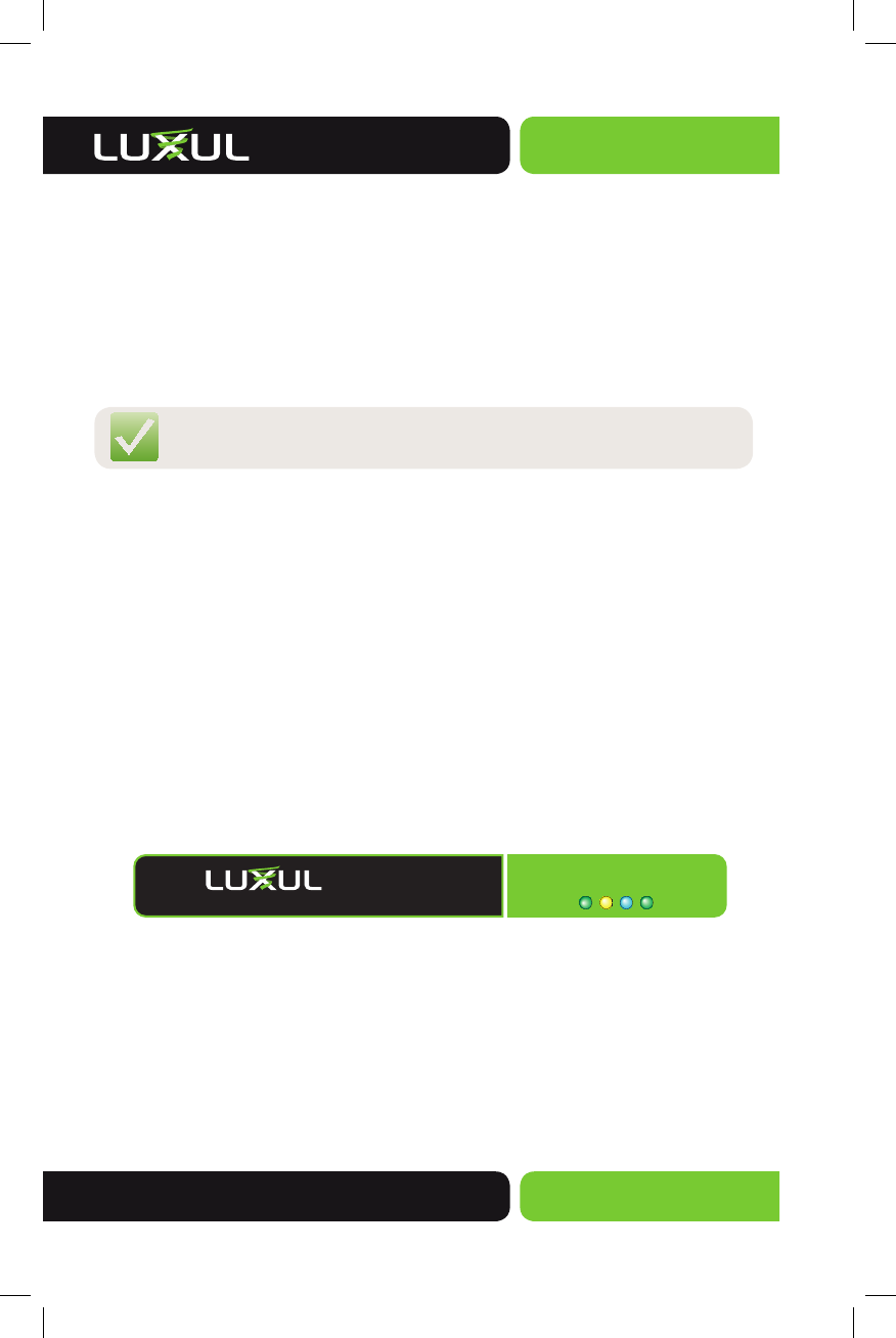
XAP-1230 LED Description
The XAP-1230 has four LEDs, positioned horizontally on the bottom right side of
the front of the access point. When viewed left to right, LEDs are as follows: 1)
Power (Green); 2) LAN Link/Activity (Amber); 3) WLAN Status (Blue); and 4) Bridge
Mode (Green).
PWR LAN BRGWLAN
XAP-1230
High Power Wireless 300N Commercial Grade AP
XAP-1230 LEDs

Quick Install Guide
XAP-1230
14203 Minuteman Drive, Suite 201, Draper, UT 84020-1685 | luxul.com | 801-822-5450
LUX-QIG-XAP-1230 0317141007
4
XAP-1230 LED Indicators
Indicator Name Description
Power On The power is on
Off No power, check power connections
LAN Link/Activity On There is an active Ethernet connection
Flashing Indicates Ethernet activity
Off There is no active Ethernet connection
WLAN Status On The wireless radio is active and wireless access is
enabled
Off The wireless radio is not active and wireless access
is disabled
Bridge Mode On Bridge is connected
Flashing Bridge Mode enabled but not connected
Off The AP is in default “Access Point” mode.
At startup, the Green Power LED will stay on while the amber LAN Link light flashes. The
blue LED will come on once the XAP-1230 wireless radio is active.
PoE Injector LED Indicators
Name Status Function
PWR On Power is connected to the PoE Injector
Off Injector is not receiving power
Simply Connected
© 2014 Luxul. All Rights Reserved.
Other trademarks and registered trademarks are the property of their respective owners
5
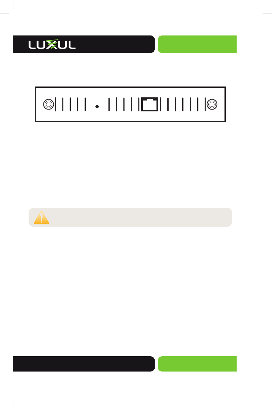
Back Panel
The back of the XAP-1230 provides two SMA antenna connectors and one RJ-45
connection that is used to deliver both power and data to the access point.
RESET
XAP-1230 Rear Panel
Reset Button:
The Reset button is used to clear the current settings of the XAP-1230 and restore
factory default settings.
To Restore the Default Settings: With the XAP-1230 powered on, press and hold
the Reset button for 15 seconds. When all the LEDs except the power LED turn off,
release the reset button. The power LED will stay solid. The XAP-1230 will be set to
factory defaults.
CAUTION: Pressing and holding the Reset button will remove any
custom configurations done to the XAP-1230.
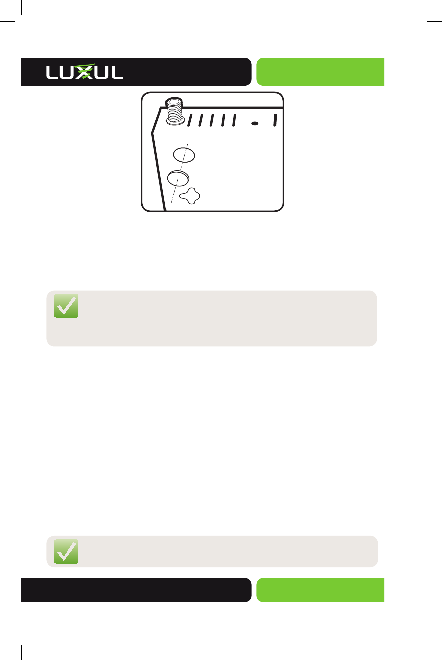
Bottom Panel
The Bottom of the XAP-1230 has two key holes to allow for easy and flexible
mounting on a wall or other solid surface. For desktop or shelf mounting, it also
has guides for placement of the four rubber feet provided.
PREPARING FOR INSTALLATION
System and Power Requirements
Computer supporting TCP/IP and equipped with a Web browser. Supported
Web browser versions include, Microsoft IE 8.0 and up, Mozilla Firefox 10 and up,
Safari 2.0 and up, Google Chrome 4.0 and up, Opera 10 and up. The Web browser
is used to configure the XAP-1230.
The PoE injector power supply requires AC100V ~ 240V, 50Hz ~ 60Hz.
Quick Install Guide
XAP-1230
14203 Minuteman Drive, Suite 201, Draper, UT 84020-1685 | luxul.com | 801-822-5450
LUX-QIG-XAP-1230 0317141007
6
XAP-1230 INSTALLATION
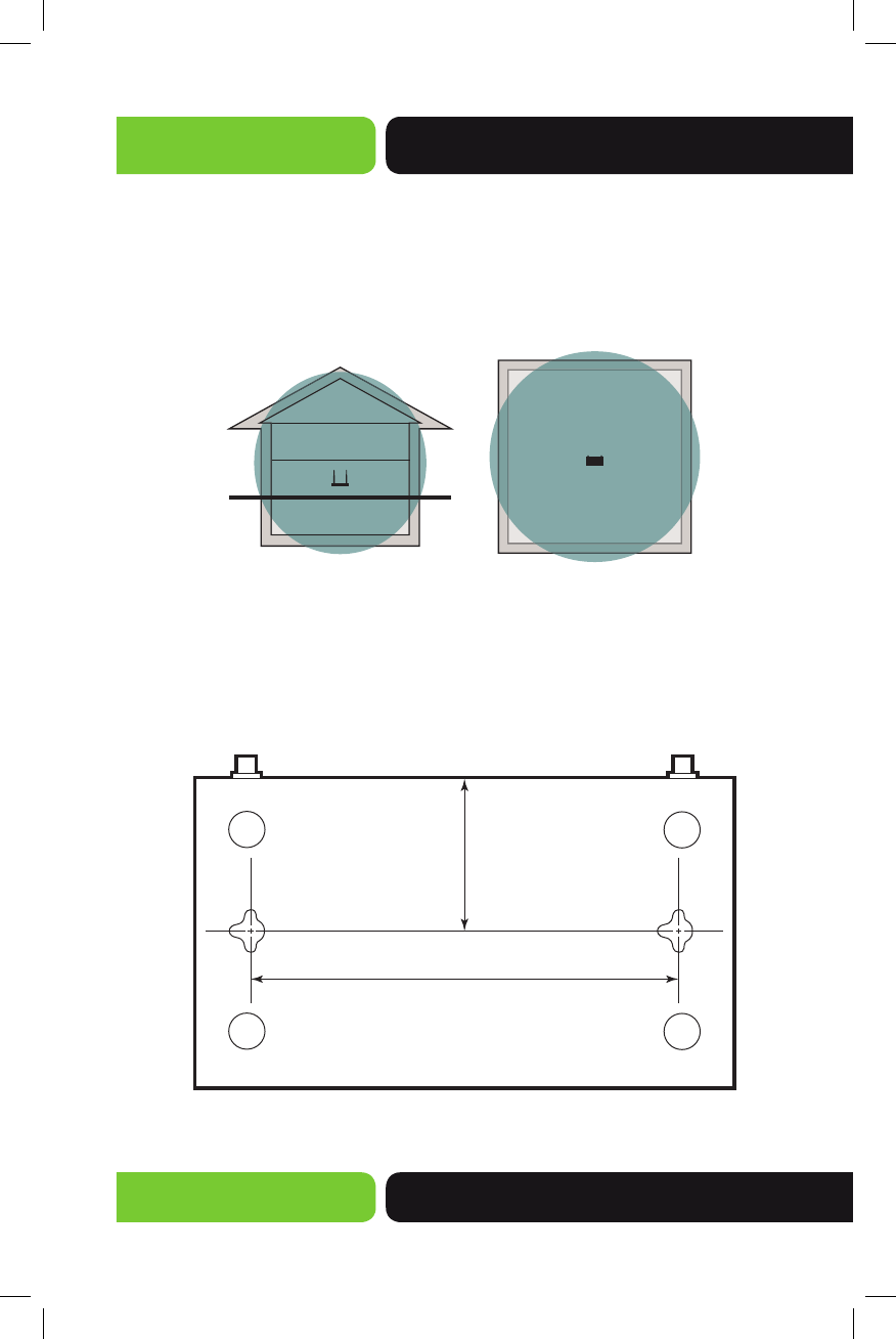
Access Point Placement
This XAP-1230 uses omni-directional antennas designed to provide 360 degrees of
coverage. For maximum effi ciency, it should be placed as close as possible in the
center of the area in which you would like to provide coverage.
XAP-1230 Coverage Pattern
Mounting the Access Point on a Wall
The XAP-1230 can be mounted directly to a wall. It can also be placed on a desktop,
shelf, or other fl at surface. Once the location has been selected, mounting the access
point directly to the wall or place it on a fl at surface as demonstrated below:
5.875”
149.2mm
2.1”
53.3mm
Mounting holes to secure the XAP-1230 to a wall
Simply Connected
© 2014 Luxul. All Rights Reserved.
Other trademarks and registered trademarks are the property of their respective owners
7
Install Included Rubber Feet in the Impressions in the bottom of the XAP-1230
Connecting the Ethernet Cable
With the XAP-1230 properly mounted and the Antennas installed, you can now
plug the Ethernet Cable into the RJ-45 connector.
NOTE: Category-5, super Category-5 or Category-6 unshielded twisted
pair (CAT5/CAT5e/CAT6 UTP) cables can be used. For best
results, it is recommended that Category-6 shielded twisted pair
be used to ensure stable data transmission at highest data rates.
Connecting to the Power Source
The XAP-1230 is PoE ready and supports 802.3at PoE. A PoE injector is included
with the device. To apply power, simply connect the opposite end of the Ethernet
cable to which the access point is already connected to the provided PoE injector
or other PoE switch or injector. An Ethernet cable length of up to 300 feet can be
used. DO NOT yet apply power to the PoE injector or switch.
PoE Injector Setup
Data In: Connect an Ethernet cable from your router or switch
to the Data In port of the included PoE Injector
Data & Power Out: Connect an Ethernet cable from the Data & Power Out
port of the included PoE Injector to the PoE Port of the XAP-1230
AC Power: Connect the included AC Cord to the Power Input of the Included
Injector first and then to the AC outlet.
NOTE: The XAP-1230 is not a router and will need to be connected to
a network with a router in order to deliver Internet access.

Quick Install Guide
XAP-1230
14203 Minuteman Drive, Suite 201, Draper, UT 84020-1685 | luxul.com | 801-822-5450
LUX-QIG-XAP-1230 0317141007
8
Power
Source
POE
Injector
From your
Router or Switch
XAP-1230
DATA IN
DATA &
PWR OUT
The PoE Injector combines power and data to the XAP-1230
CONFIGURATION
Default IP Address
The XAP-1230 is not equipped with internal DHCP server. If connected to a Luxul
Router, configuration will be automatic. Otherwise, the IP address of the computer
for login and configuration will need to be manually configured. The table below
lists the default parameters of the XAP-1230.
Parameter: Default Value
Default IP address: 192.168.0.10
Default user name: admin
Default password: admin
The Luxul Xen XAP-1230 default IP addresss is 192.168.0.10. If the IP address of your
router is not set to the 192.168.0.X network, a temporary static IP address must be
set on the computer to be used for configuration. To do so, set the IP address of
the computer to the 192.168.0.X range and then use the default IP address of your
XAP-1230 as the Gateway/Router. Once configured, set the computer IP configura-
tion back to “Obtain Automatically/DHCP.”

Simply Connected
© 2014 Luxul. All Rights Reserved.
Other trademarks and registered trademarks are the property of their respective owners
9
NOTE: Go to http://luxul.com/how-to-videos for videos about
changing the IP address of your Operating System.
Connect a Client Device
Connecting a Wireless Client Device: Connect the client device to the XAP-1230
default wireless network LuxulXen1200. This wireless network will run in Open
Security mode. A passphrase is not required until Wireless Security is configured.
Login
Login to the XAP-1230 with the following steps:
1. Open a Web browser, and enter 192.168.0.10. The access point login screen
will appear.
2. Enter the user name and password (default user name and default password
are both set as “admin”), and then click “OK” to login to the access point
configuration interface.
ADVANCED SETTINGS
For advanced settings information go to luxul.com
WARNINGS AND SAFETY INFORMATION
Verify that the electrical circuits have appropriate grounding and overload protection.
Attach only approved power cords to the device.

Quick Install Guide
XAP-1230
14203 Minuteman Drive, Suite 201, Draper, UT 84020-1685 | luxul.com | 801-822-5450
LUX-QIG-XAP-1230 0317141007
10
Verify there is adequate ventilation around the device, and that ambient temperatures meet
equipment operation specifications.
The XAP-1230 is designed for indoor use only. DO NOT place this outdoors.
DO NOT install in or near hot or humid places, such as a kitchen or bathroom. Take care to
minimize exposure to excessive heat or moisture.
Small parts and plastic bags used for packaging may be harmful to small children. KEEP All
ACCESSORIES OUT OF THE REACH OF CHILDREN!
The XAP-1230 may become hot when in use for extended time periods. This is normal and is not a
malfunction. DO NOT install where it will be exposed to paper, cloth or other flammable materials.
REGULATORY COMPLIANCE
The device complies with internationally recognized standards covering human exposure to elec-
tromagnetic fields from radio devices. This equipment also complies with FCC radiation exposure
set forth for an uncontrolled environment. In order to avoid the possibility of exceeding the FCC
radio frequency exposure limits, human proximity to the antenna shall not be less than 20 cm (8
inches) during normal operation.
Unauthorized antennas, modifications, or attachments could cause damage and may violate regula-
tory approvals. Any changes or modifications not expressly approved by the party responsible for
compliance could void the authority to operate the equipment.
The equipment version marketed in the U.S. is restricted to usage of channels 1-11 only.
Health and Safety Recommendations
Warnings for the use of Wireless Devices: Please observe all warning notices with regard to the
usage of wireless devices
Potentially Hazardous Atmospheres: You are reminded of the need to observe restrictions on the
use of radio devices in fuel depots, chemical plants etc. and areas where the air contains chemicals
or particles (such as grain, dust, or metal powders).
Safety in Hospitals: Wireless devices transmit radio frequency energy and may affect medical
electrical equipment. When installed adjacent to other equipment, it is advised to verify that the
adjacent equipment is not adversely affected.
RF Exposure Guidelines
Safety Information: The device complies with internationally recognized standards covering
human exposure to electromagnetic fields from radio devices.
Warning: Exposure to Radio Frequency (RF) Radiation:
The radiated output of this device is below the FCC radio frequency exposure limits. Nevertheless,
the device should be used in such a manner that the potential for human contact during normal
operation is minimized.
The end user must avoid any extended human RF exposure directly in front
of the device, up to a distance of 20cm, when unit is on.

Simply Connected
© 2014 Luxul. All Rights Reserved.
Other trademarks and registered trademarks are the property of their respective owners
11
When servicing the equipment and selecting a location for the antennas, it is important to note
that a minimum distance of 20cm is required between personnel and the device or antenna to
comply with the radio frequency exposure limit.
The antenna used for this transmitter must be installed to provide a separation distance of at
least 20cm from all persons and must not be co-located or operating in conjunction with any
other antenna or transmitter.
The following safety precautions should be observed:
Do not touch or move the antenna while the unit is transmitting or receiving.
Do not hold any component containing the radio such that the antenna is very close or touching
any exposed parts of the body, especially the face or eyes, while transmitting.
Do not operate the radio or attempt to transmit data unless the antenna is connected; this
behavior may cause damage to the radio.
FCC Statement—Wireless FCC 2.4GHz 802.11bgn
This device complies with Part 15 of the FCC Rules. Operation is subject to the following two
conditions: (1) This device may not cause harmful interference, and (2) this device must accept any
interference received, including interference that may cause undesired operation.
This equipment has been tested and found to comply with the limits for a Class B digital device,
pursuant to Part 15 of the FCC Rules. These limits are designed to provide reasonable protection
against harmful interference in a residential installation. This equipment generates, uses and can
radiate radio frequency energy and, if not installed and used in accordance with the instructions,
may cause harmful interference to radio communications. However, there is no guarantee that
interference will not occur in a particular installation. If this equipment does cause harmful interfer-
ence to radio or television reception, which can be determined by turning the equipment off and
on, the user is encouraged to try to correct the interference by one of the following measures:
Reorient or relocate the receiving antenna.
Increase the separation between the equipment and receiver.
Connect the equipment into an outlet on a circuit different from that to which the
receiver is connected.
Consult the dealer or an experienced radio/TV technician for help.
FCC Caution: Any changes or modifications not expressly approved by the party responsible for
compliance could void the user’s authority to operate this equipment.
This transmitter must not be co-located or operating in conjunction with any other
antenna or transmitter.
Radiation Exposure Statement
This equipment complies with FCC radiation exposure limits set forth for an uncontrolled environ-
ment. This equipment should be installed and operated with minimum distance 20cm between the
radiator & your body.
This radio transmitter with the model:Q5003 has been approved by Industry Canada to operate
with the antenna types listed below with the maximum permissible gain and required antenna
impedance for each antenna type indicated. Antenna types not included in this list, having a
gain greater than the maximum gain indicated for that type, are strictly prohibited for use with
this device.
Le présent émetteur radio avec le modèle: Q5003 a été approuvé par Industrie Canada pour
fonctionner avec les types d'antenne énumérés ci-dessous et ayant un gain admissible maximal
et l'impédance requise pour chaque type d'antenne. Les types d'antenne non inclus dans cette
liste, ou dont le gain est supérieur au gain maximal indiqué, sont strictement interdits pour
l'exploitation de l'émetteur
Antenna Model Name
Antenna Type
Gain(dBi)
Q5003
Dipole
5.28