Lyngsoe Systems ADM RFID READER User Manual ADM UserMan
Lyngsoe Systems Ltd. RFID READER ADM UserMan
Users Manual

ADM
User Manual
- for end users -

ADM Technical Description RFID-LSCAN
File: ADM UserMan.doc Page 2 of 12
Status: Rev1 Last Update: 9/21/2010 3:49:00 PM
Revision History Table
Revision Changes Since Previous Revision
Rev1
This is the initial release of the document

ADM Technical Description RFID-LSCAN
File: ADM UserMan.doc Page 3 of 12
Status: Rev1 Last Update: 9/21/2010 3:49:00 PM
TABLE OF CONTENTS
1. OVERVIEW 6
1.1
Main Characteristics 6
1.2
Physical concept 7
2. MODES OF OPERATION 8
3. FUNCTIONAL ARCHITECTURE 8
3.1
LF Exciter 8
3.1.1
Operation 8
3.1.2
Excitation Distance 9
3.2
UHF Receiver 10
3.2.1
Receive Distance 10
3.2.2
Tag message filtration 10
3.3
GSM Modem 10
3.4
Test Tag 10
3.5
USB Ports 10
3.6
LEDs 10
3.6.1
Power 11
3.6.2
Busy 11
3.6.3
GSM 11
3.7
Power Supply System 11
3.7.1
Battery pack 11
3.7.2
Backup battery 12
4. ENVIRONMENTAL 12
5. REGULATORY 12

ADM Technical Description RFID-LSCAN
File: ADM UserMan.doc Page 4 of 12
Status: Rev1 Last Update: 9/21/2010 3:49:00 PM
LIST OF FIGURES
Figure 1 – ADM Concept _____________________________________________________________________ 6
Figure 2 - ADM Assembly ____________________________________________________________________ 7
Figure 3 - ADM Main Unit and Battery Pack _____________________________________________________ 7
Figure 4 – LF Excitation Zone _________________________________________________________________ 9
Figure 5 – Door Slot Installation _______________________________________________________________ 9
LIST OF TABLES
Table 1 – Excitation Distance _________________________________________________________________ 9
Table 2 – UHF Receive Distance _____________________________________________________________ 10
Table 3 – Battery Pack Characteristics ________________________________________________________ 11
Table 4 – Backup Battery Characteristics ______________________________________________________ 12

ADM Technical Description RFID-LSCAN
File: ADM UserMan.doc Page 5 of 12
Status: Rev1 Last Update: 9/21/2010 3:49:00 PM
Definition of terms
Tag Collection Period The time (typically 24 hours) interval between two
consecutives scheduled data SMS transmissions
Read Time Table A table that defines the frequency of tag reading cycles
within 24 hours
SMS Time Table A table that defines the time of the day when the data
SMS is sent
Tag Registration First read of a tag in a tag collection period
Acronyms
ADM Automated Delivery Measurement
GSM Global Standard for Mobiles
LOS Line-of-Sight
RTT Read Time Table
RTC Real Time Clock
SIM Subscriber Identity Module
SMS Short Message Service
STT SMS Time Table
TCP Tag Collection Period
UHF Ultra High Frequency
UTC Coordinated Universal Time
ADM Technical Description RFID-LSCAN
File: ADM UserMan.doc Page 6 of 12
Status: Rev1 Last Update: 9/21/2010 3:49:00 PM
1. OVERVIEW
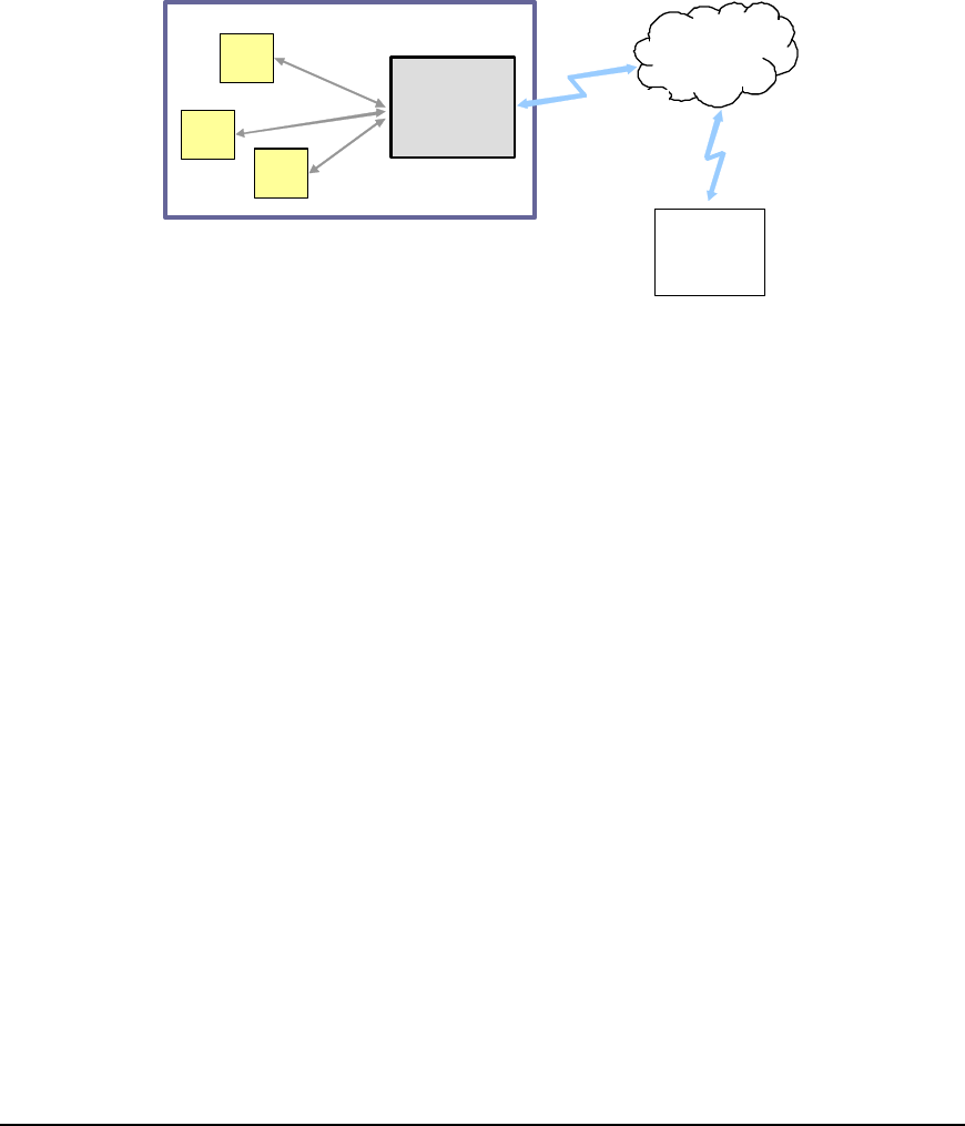
ADM is a remote data collection device used to provide accurate last mile mail delivery
measurements. The ADM is placed inside a mailbox or above a mail door slot. When a test letter
(letter that contain a tag) is placed in the proximity of an ADM, the tag inside the envelope is
excited and its unique ID is read. The ID and the time of read are then transmitted to a backend
application over the GSM network using SMS.
The ADM concept is illustrated in Figure 1.
Test
Letter
Mailbox
GSM
Network
Backend
Application
ADM
Test
Letter
Test
Letter
Figure 1 – ADM Concept
1.1 Main Characteristics
Overall Dimensions (target)
- Length: 185mm (including battery pack)
- Width: 85mm
- Height: 20mm (with small battery pack)
Reader
- 433MHz receiver, Integrated antenna
- 125kHz transmitter, Integrated antenna
GSM Modem
- 2-Watt EGSM 900/GSM 850 radio section
- 1-Watt GSM 1800/1900 radio section
- Integrated antenna
Data Backup
- USB Flash Drive
Digital Interface
- Micro B USB receptacle for debug and service console
LEDs
- Power, Busy and GSM
ADM Technical Description RFID-LSCAN
File: ADM UserMan.doc Page 7 of 12
Status: Rev1 Last Update: 9/21/2010 3:49:00 PM
Power
- Li-Polymer rechargeable cells
Environment
- IP64 with battery pack
- IP20 w/o battery pack
- RoHS compliant
1.2 Physical concept
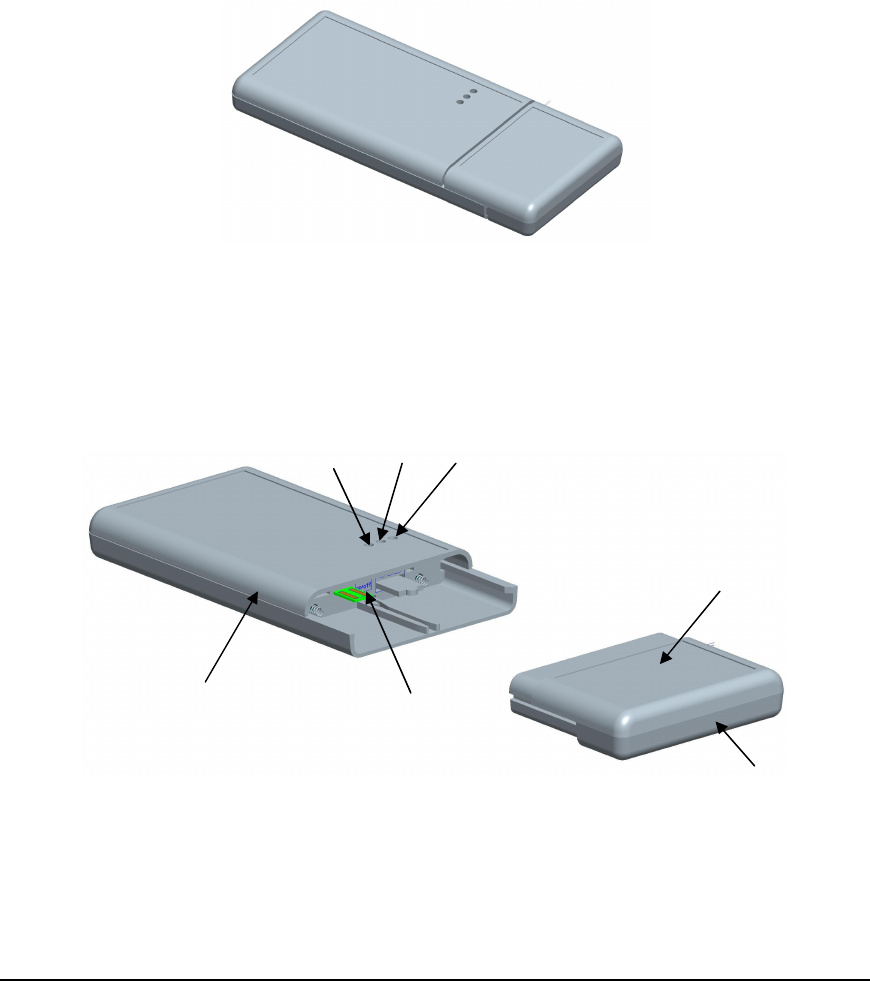
The ADM consists of a main unit and a detachable battery pack. The ADM physical concept is
illustrated in Figs. 2-3
Figure 2 - ADM Assembly
Figure 3 - ADM Main Unit and Battery Pack
Main Unit
Battery Pack
GSM
LED
Busy
LED
Power
LED
Charge
LED
ON/OFF
Switch

ADM Technical Description RFID-LSCAN
File: ADM UserMan.doc Page 8 of 12
Status: Rev1 Last Update: 9/21/2010 3:49:00 PM
Main physical characteristics
• Push-in push-out (double click) battery pack lock mechanism
• ON/OFF slide switch
• Reset button
2. MODES OF OPERATION
The ADM has two modes of operation: a) normal mode (power saving), b) continuous mode:
a) In normal mode, the unit is in sleep most of the time. It wakes-up regularly, based on a
Read Time Table (RTT). The RTT specifies the frequency of reads (e.g. every five
minutes) during a specific time interval (e.g. 8 hours). The RTT spans over 24 hours. One
can define up to eight time intervals in 24 hours; each interval can have a different read
frequency. In power saving mode, a read cycle can also be triggered by
vibration/shock/motion (if the vibration sensor is enabled). The power saving mode is
recommended for mailbox installation.
b) In continuous mode, the ADM is on all the time. The exciter generates continuously low
power LF field designed to catch test letters that are momentarily in the proximity of the
unit. This mode is intended for door slot installations.
One can combine power saving mode and continuous mode in the RTT. As an example, an ADM
can read tags continuously from 7:00AM to 4:00PM, every 10 minutes from 4:00PM to 9:00PM
and no reads from 9:00PM to 7:00AM next day.
3. FUNCTIONAL ARCHITECTURE
Essentially, the ADM is a battery powered, active RFID reader equipped with a GSM modem. It
performs the following main operations:
a) Generates LF excitation field
b) Receives UHF signal from tags
c) Transmits data and status information over SMS
d) Receives configuration command and parameter over SMS
3.1 LF Exciter
3.1.1 Operation
The exciter generates the low frequency (LF) field that is used to wake up tags. Once the tag
receives the LF signal, it responses on UHF. The excitation signal incorporates a (programmable)
unique address (LF field identifier). This LF identifier is received by the tag’s 125 kHz receiver and
ADM Technical Description RFID-LSCAN
File: ADM UserMan.doc Page 9 of 12
Status: Rev1 Last Update: 9/21/2010 3:49:00 PM
it is echoed back on UHF. In this way, the RFID system is able to determine which ADM excited
the tag.
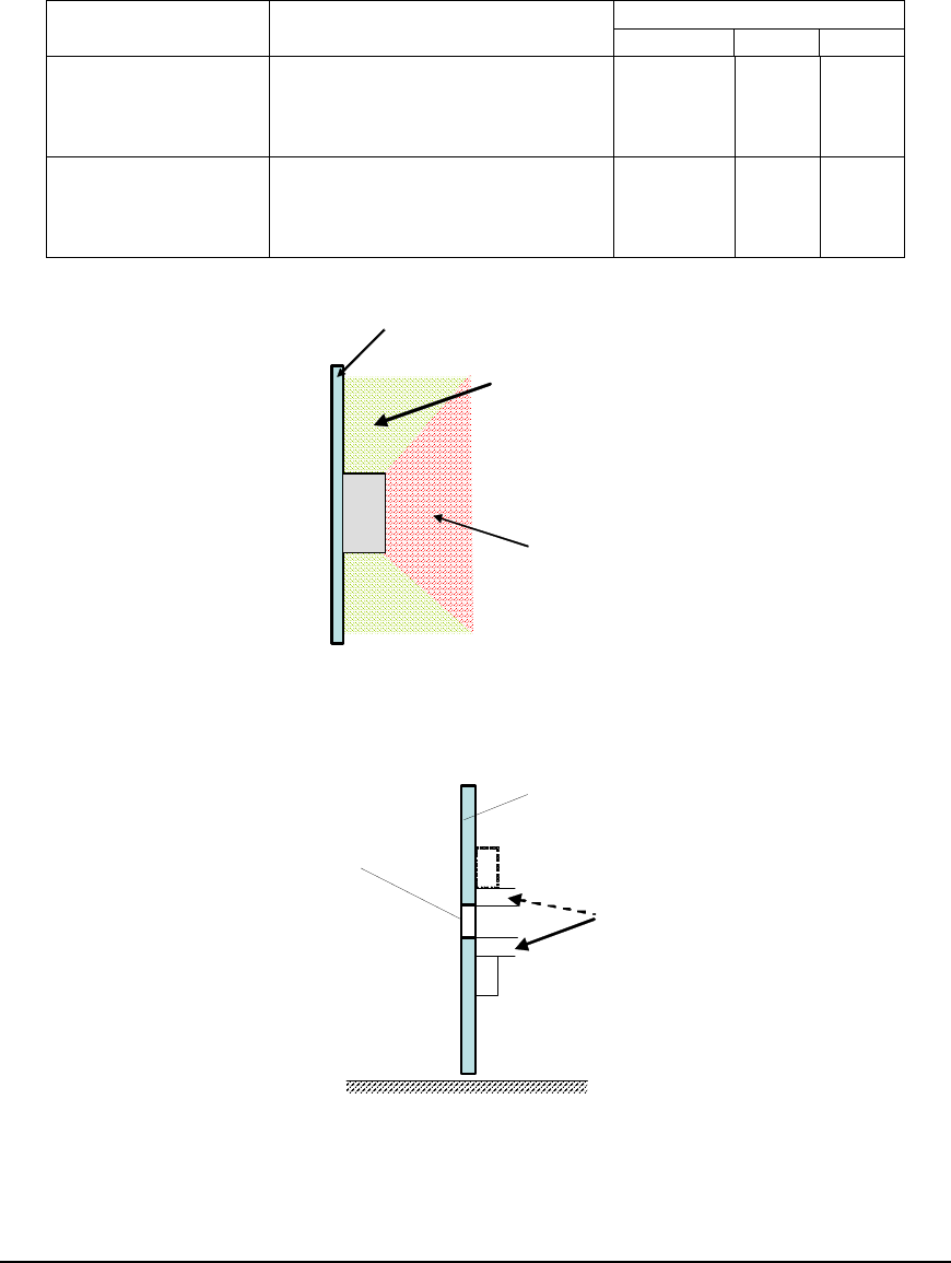
3.1.2 Excitation Distance
Table 1 – Excitation Distance
Value Mode of Operation Conditions
Min Typ. Max
Power saving and
continuous normal-
excitation modes
ADM installed on metallic
surface, tag in front of the unit
(±45
o
angle), all tag orientations,
max. field strength
35cm
(see
Figure 6)
Continuous low-
power excitation
mode
ADM installed on metallic
surface, tag parallel to the long
side of the ADM, min. field
strength
5cm (see
Figure 7)
ADM
Metallic
surface
Excitation
distance
>
35cm
Excitation
distance
<
35cm
Figure 4 – LF Excitation Zone
mail slot
door
5cm
ADM ADM
Figure 5 – Door Slot Installation

ADM Technical Description RFID-LSCAN
File: ADM UserMan.doc Page 10 of 12
Status: Rev1 Last Update: 9/21/2010 3:49:00 PM
3.2 UHF Receiver
The UHF receiver is a narrowband FSK receiver operating in the 433.92 MHz frequency band.
3.2.1 Receive Distance
Table 2 – UHF Receive Distance
Value
Conditions Min Typ. Max
No obstacles, any tag orientation 10m
3.2.2 Tag message filtration
Only the first read of a tag in a TCP is stored (“tag registration”). However, the ADM can be
programmed to also store the last read of a tag in a TCP (i.e. last time the tag was read prior to be
removed from the mail box). In the event a tag is removed before the second read cycle in a TCP,
the two registrations are identical. This feature is not applicable in continuous mode.
Tag registrations are collected in a non-volatile buffer (“tag buffer”). The tag buffer can store up to
60 registrations. After the capacity of the tag buffer is reached, new registrations are ignored.
3.3 GSM Modem
The ADM communicates with the server (backend) over the GSM network using SMS. It sends
data and unit status information and receives configuration commands and parameters. The
operating frequencies in GSM, DCS and PCS modes are conform to the GSM specifications. The
GSM modem uses an 880~960MHz, 1710~1990 MHz, 0dB Gain integrated antenna.
The GSM modem supports phase 2 GSM11.14 – SIM 1.8V and 3V. The SIM card reader allows
for hot removal of the SIM.
3.4 Test Tag
The ADM integrates a test tag used to monitor unit’s health. The test tag consists of a low power
UHF transmitter, a LF (125kHz) receiver and a microcontroller. The test tag is powered on once a
day. After that, it receives the ADM LF field. Once excited, the test tag transmits a burst of 40
identical messages pseudo-randomly spaced in time. These messages are received by ADM’s
434 MHz receiver and processed like any other messages. Their presence confirms that the ADM
is functioning properly even if no other messages from other tags are registered.
3.5 USB Ports
The ADM has two USB ports: a host port and a slave port. The USB ports are not accessible in
normal operation. One has to remove the battery pack in order to have access to the two ports.
The two ports are only for debug and service and should not be used by the end user.
3.6 LEDs
The main unit is equipped with three LEDs: Power, Busy and GSM. They are normally off and are
only activated for 20 seconds each time when the battery pack is inserted or removed.

ADM Technical Description RFID-LSCAN
File: ADM UserMan.doc Page 11 of 12
Status: Rev1 Last Update: 9/21/2010 3:49:00 PM
3.6.1 Power
When activated, the power LED is solid white if the power system is OK. If an uncharged battery
pack is inserted, the power LED flashes 3 times/second (provided that the internal battery is not
discharged as well).
3.6.2 Busy
When activated, the busy LED (blue) is on while the unit is busy (e.g. booting, reading tags,
sending and receiving SMS).
3.6.3 GSM
When activated, the GSM LED indicates the quality of the GSM signal:
• If the GSM signal is strong enough, the LED is green
• If the GSM signal is unavailable or marginal, the LED is red
The GSM signal quality information is only collected during SMS operation and therefore the
indication accuracy depends on how long the unit has been in operation.
3.7 Power Supply System
The ADM is powered by Li-Polymer rechargeable cells. The main power source is the external
battery pack. The secondary source is a backup battery, built inside the main unit. The battery
pack powers the ADM circuitry and at the same time charges the backup cell. The ADM works
properly even if the backup battery is fully discharged, as long as the battery pack is connected
and not depleted. The user only needs to charge the battery pack.
3.7.1 Battery pack
The battery pack has two ports: a charging port (micro-B USB receptacle) and a load port (battery
contacts). The battery pack can be recharged from a dedicated charger or a PC USB port.
The battery pack has an LED to indicate the charging status:
• LED is red while charging
• LED turns green when the pack is fully charged
• LED goes off when the charger is disconnected
Table 3 – Battery Pack Characteristics
Value
Parameter Conditions Min Typ. Max
Power saving mode, excitation every
5min, one SMS/day, max. LF field
28 days
Battery Life Continuous mode, one SMS/day, min.
field strength
7 days
Charge Time 1A charging current 4 hours
Recharge Cycles 500
Charge
Temperature
0
o
C +45
o
C
Storage 1 year -20
o
C +45
o
C

ADM Technical Description RFID-LSCAN
File: ADM UserMan.doc Page 12 of 12
Status: Rev1 Last Update: 9/21/2010 3:49:00 PM
3.7.2 Backup battery
The main unit is equipped with a backup battery that allows the unit to continue operate for a
limited time without the battery pack. The backup cell is only used when the battery pack is
depleted or not connected.
Table 4 – Backup Battery Characteristics
Value Parameter Conditions
Min Typ. Max
Power saving mode,
excitation every 5min, one
SMS/day, max. LF field
3 days
Battery Life (per charge) Continuous mode, one
SMS/day, min. field strength
16 hours
Recharge Cycles 300
Charge Temperature 0
o
C +45
o
C
Storage 1 year -20
o
C +45
o
C
4. ENVIRONMENTAL
• Operating temperature range: -20
o
C - +60
o
C (except USB flash drive)
• Storage temperature range: -20
o
C - +45
o
C (1 year)
• Drop test: 1m drop on concrete surface, no structural and functional damage
5. REGULATORY
FCC compliance notice
Caution:
Changes or modifications not expressly approved by the party responsible for compliance
could void the user’s authority to operate the equipment.
NOTE: This equipment has been tested and found to comply with the limits for a Class B
digital device, pursuant to part 15 of the FCC Rules. These limits are designed to provide
reasonable protection against harmful interference in a residential installation. This equipment
generates, uses, and can radiate radio frequency energy and, if not installed and used in
accordance with the instructions, may cause harmful interference to radio communications.
However, there is no guarantee that interference will not occur in a particular installation. If
this equipment does cause harmful interference to radio or television reception, which can be
determined by turning the equipment off and on, the user is encouraged to try to correct the
interference by one or more of the following measures:
—Reorient or relocate the receiving antenna.
—Increase the separation between the equipment and receiver.
—Connect the equipment into an outlet on a circuit different from that to which the receiver is
connected.
—Consult the dealer or an experienced radio/TV technician for help.
IC compliance
This Class B digital apparatus complies with Canadian ICES-003.
Operation is subject to the following two conditions: (1) this device may not cause
interference, and (2) this device must accept any interference, including interference that may
cause undesired operation of the device.