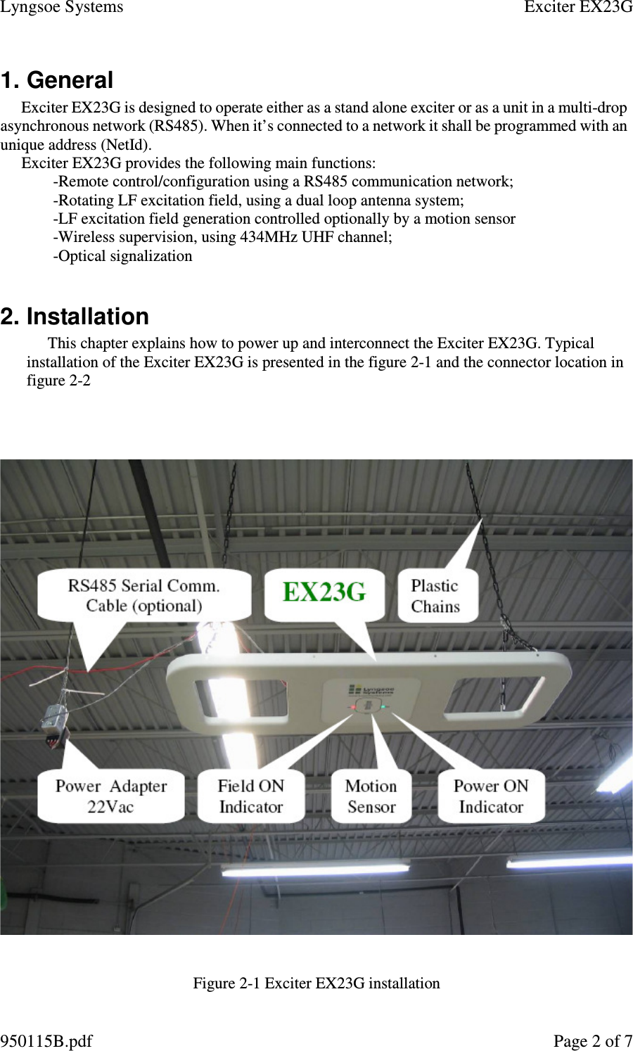
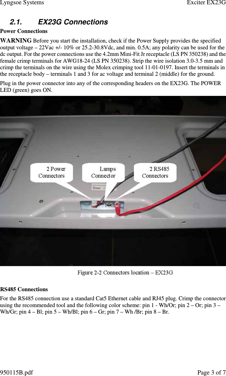
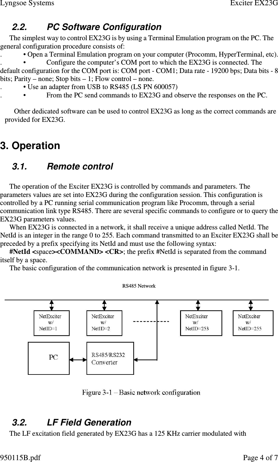
Lyngsoe Systems EX23G EXCITER EX23G User Manual EX23 Usr Manu 950115C
Lyngsoe Systems Ltd. EXCITER EX23G EX23 Usr Manu 950115C
UserManual.wiki
>
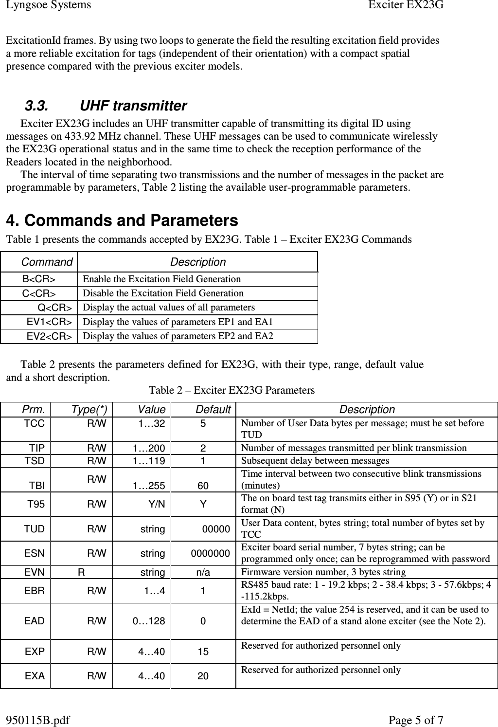
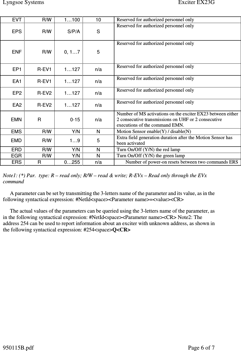
Lyngsoe Systems
>
EX23G User Manual
>
USERS MANUAL
Contents
1.
USERS MANUAL
2.
users manual
USERS MANUAL
Navigation menu
Upload a User Manual
Namespaces
Wiki Guide
HTML
PDF
Info
Views
User Manual
Discussion / Help
Navigation