Lyngsoe Systems EX23G EXCITER EX23G User Manual EX23 Usr Manu 950115C
Lyngsoe Systems Ltd. EXCITER EX23G EX23 Usr Manu 950115C
Contents
- 1. USERS MANUAL
- 2. users manual
users manual

Lyngsoe Systems Exciter EX23G
950115B.pdf Page 1 of 7
Exciter EX23G
User’s Guide
Revision C – July 21, 2006
Lyngsoe Systems Exciter EX23G
950115B.pdf Page 2 of 7
1. General
Exciter EX23G is designed to operate either as a stand alone exciter or as a unit in a multi-drop
asynchronous network (RS485). When it’s connected to a network it shall be programmed with an
unique address (NetId).
Exciter EX23G provides the following main functions:
-Remote control/configuration using a RS485 communication network;
-Rotating LF excitation field, using a dual loop antenna system;
-LF excitation field generation controlled optionally by a motion sensor
-Wireless supervision, using 434MHz UHF channel;
-Optical signalization
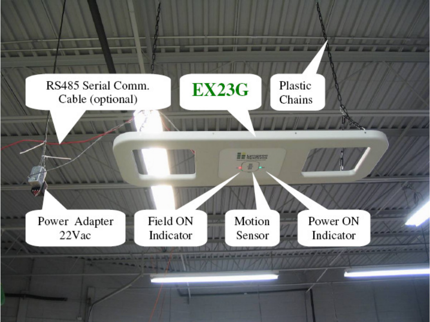
2. Installation
This chapter explains how to power up and interconnect the Exciter EX23G. Typical
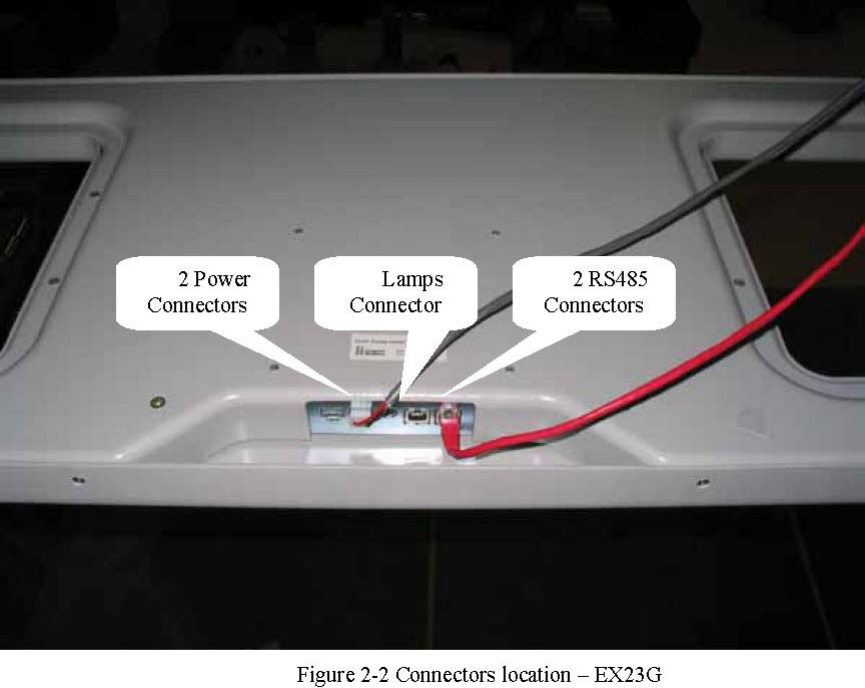
installation of the Exciter EX23G is presented in the figure 2-1 and the connector location in
figure 2-2
Figure 2-1 Exciter EX23G installation
Lyngsoe Systems Exciter EX23G
950115B.pdf Page 3 of 7
2.1. EX23G Connections
Power Connections
WARNING
Before you start the installation, check if the Power Supply provides the specified
output voltage – 22Vac +/- 10% or 25.2-30.8Vdc, and min. 0.5A; any polarity can be used for the
dc output. For the power connections use the 4.2mm Mini-Fit Jr receptacle (LS PN 350238) and the
female crimp terminals for AWG18-24 (LS PN 350238). Strip the wire isolation 3.0-3.5 mm and
crimp the terminals on the wire using the Molex crimping tool 11-01-0197. Insert the terminals in
the receptacle body – terminals 1 and 3 for ac voltage and terminal 2 (middle) for the ground.
Plug in the power connector into any of the corresponding headers on the EX23G. The POWER
LED (green) goes ON.
RS485 Connections
For the RS485 connection use a standard Cat5 Ethernet cable and RJ45 plug. Crimp the connector
using the recommended tool and the following color scheme: pin 1 - Wh/Or; pin 2 – Or; pin 3 –
Wh/Gr; pin 4 – Bl; pin 5 – Wh/Bl; pin 6 – Gr; pin 7 – Wh /Br; pin 8 – Br.
Lyngsoe Systems Exciter EX23G
950115B.pdf Page 4 of 7
2.2. PC Software Configuration
The simplest way to control EX23G is by using a Terminal Emulation program on the PC. The
general configuration procedure consists of:
. • Open a Terminal Emulation program on your computer (Procomm, HyperTerminal, etc).
. • Configure the computer’s COM port to which the EX23G is connected. The
default configuration for the COM port is: COM port - COM1; Data rate - 19200 bps; Data bits - 8
bits; Parity – none; Stop bits – 1; Flow control – none.
. • Use an adapter from USB to RS485 (LS PN 600057)
. • From the PC send commands to EX23G and observe the responses on the PC.
Other dedicated software can be used to control EX23G as long as the correct commands are
provided for EX23G.
3. Operation
3.1. Remote control
The operation of the Exciter EX23G is controlled by commands and parameters. The
parameters values are set into EX23G during the configuration session. This configuration is
controlled by a PC running serial communication program like Procomm, through a serial
communication link type RS485. There are several specific commands to configure or to query the
EX23G parameters values.
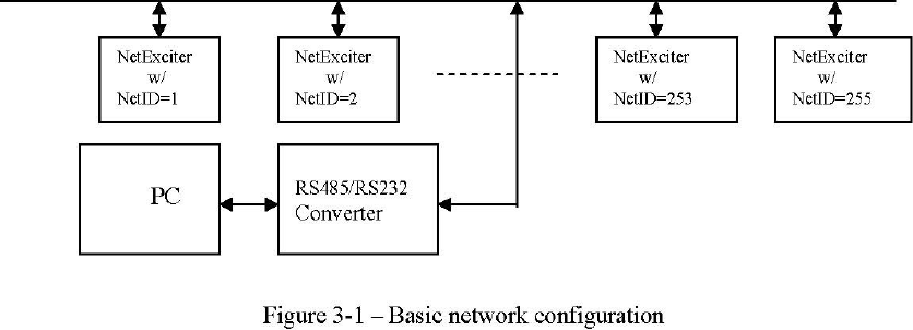
When EX23G is connected in a network, it shall receive a unique address called NetId. The
NetId is an integer in the range 0 to 255. Each command transmitted to an Exciter EX23G shall be
preceded by a prefix specifying its NetId and must use the following syntax:
#NetId <space><COMMAND> <CR>; the prefix #NetId is separated from the command
itself by a space.
The basic configuration of the communication network is presented in figure 3-1.
RS485 Network
3.2. LF Field Generation
The LF excitation field generated by EX23G has a 125 KHz carrier modulated with
Lyngsoe Systems Exciter EX23G
950115B.pdf Page 5 of 7
ExcitationId frames. By using two loops to generate the field the resulting excitation field provides
a more reliable excitation for tags (independent of their orientation) with a compact spatial
presence compared with the previous exciter models.
3.3. UHF transmitter
Exciter EX23G includes an UHF transmitter capable of transmitting its digital ID using
messages on 433.92 MHz channel. These UHF messages can be used to communicate wirelessly
the EX23G operational status and in the same time to check the reception performance of the
Readers located in the neighborhood.
The interval of time separating two transmissions and the number of messages in the packet are
programmable by parameters, Table 2 listing the available user-programmable parameters.
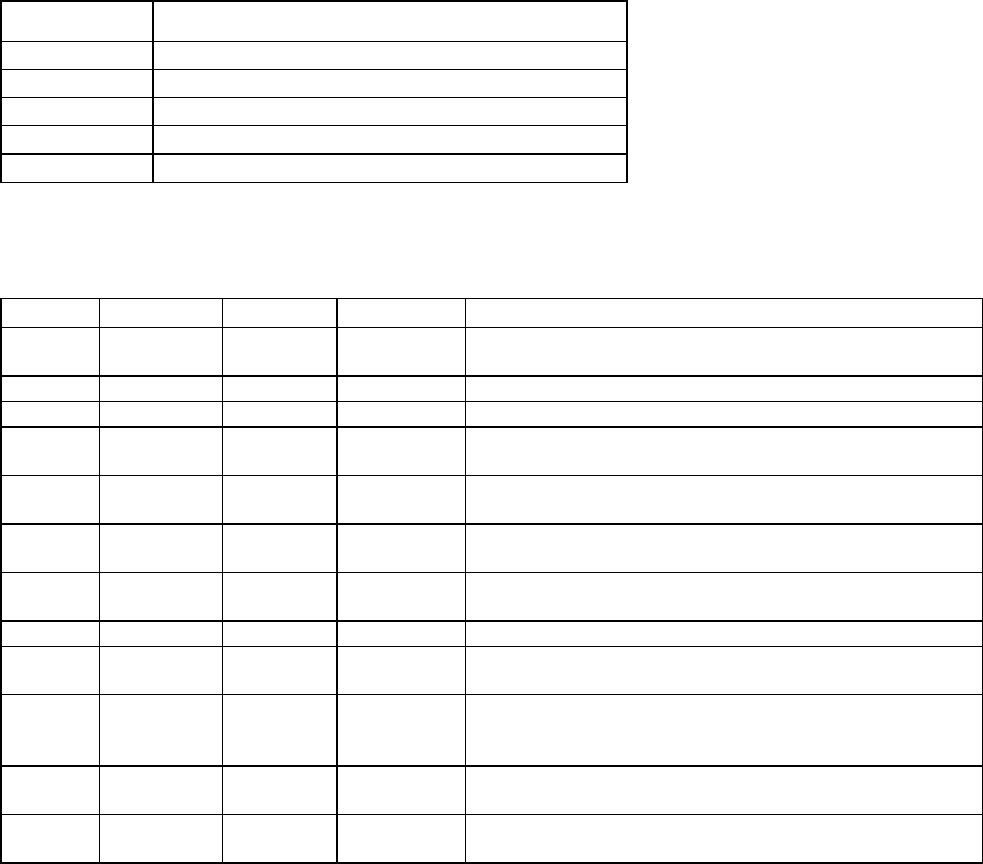
4. Commands and Parameters
Table 1 presents the commands accepted by EX23G. Table 1 – Exciter EX23G Commands
Command
Description
B<CR> Enable the Excitation Field Generation
C<CR> Disable the Excitation Field Generation
Q<CR>
Display the actual values of all parameters
EV1<CR>
Display the values of parameters EP1 and EA1
EV2<CR>
Display the values of parameters EP2 and EA2
Table 2 presents the parameters defined for EX23G, with their type, range, default value
and a short description.
Table 2 – Exciter EX23G Parameters
Prm.
Type(*)
Value
Default
Description
TCC
R/W
1…32
5 Number of User Data bytes per message; must be set before
TUD
TIP
R/W
1…200
2 Number of messages transmitted per blink transmission
TSD
R/W
1…119
1 Subsequent delay between messages
TBI
R/W
1…255
60
Time interval between two consecutive blink transmissions
(minutes)
T95
R/W
Y/N
Y The on board test tag transmits either in S95 (Y) or in S21
format (N)
TUD
R/W
string
00000
User Data content, bytes string; total number of bytes set by
TCC
ESN
R/W
string
0000000
Exciter board serial number, 7 bytes string; can be
programmed only once; can be reprogrammed with password
EVN
R string
n/a Firmware version number, 3 bytes string
EBR
R/W
1…4
1 RS485 baud rate: 1 - 19.2 kbps; 2 - 38.4 kbps; 3 - 57.6kbps; 4
-115.2kbps.
EAD
R/W
0…128
0
ExId = NetId; the value 254 is reserved, and it can be used to
determine the EAD of a stand alone exciter (see the Note 2).
EXP
R/W
4…40
15 Reserved for authorized personnel only
EXA
R/W
4…40
20 Reserved for authorized personnel only

Lyngsoe Systems Exciter EX23G
950115B.pdf Page 6 of 7
EVT
R/W
1…100
10 Reserved for authorized personnel only
EPS
R/W
S/P/A
S
Reserved for authorized personnel only
ENF
R/W
0, 1…7
5
Reserved for authorized personnel only
EP1
R-EV1
1…127
n/a Reserved for authorized personnel only
EA1
R-EV1
1…127
n/a Reserved for authorized personnel only
EP2
R-EV2
1…127
n/a Reserved for authorized personnel only
EA2
R-EV2
1…127
n/a Reserved for authorized personnel only
EMN
R 0-15
n/a
Number of MS activations on the exciter EX23 between either
2 consecutive transmissions on UHF or 2 consecutive
executions of the command EMN.
EMS
R/W
Y/N
N Motion Sensor enable(Y) / disable(N)
EMD
R/W
1…9
5 Extra field generation duration after the Motion Sensor has
been activated
ERD
R/W
Y/N
N Turn On/Off (Y/N) the red lamp
EGR
R/W
Y/N
N Turn On/Off (Y/N) the green lamp
ERS
R 0…255
n/a Number of power-on resets between two commands ERS
Note1: (*) Par. type: R – read only; R/W – read & write; R-EVx – Read only through the EVx
command
A parameter can be set by transmitting the 3-letters name of the parameter and its value, as in the
following syntactical expression: #NetId<space><Parameter name>=<value><CR>
The actual values of the parameters can be queried using the 3-letters name of the parameter, as
in the following syntactical expression: #NetId<space><Parameter name><CR> Note2: The
address 254 can be used to report information about an exciter with unknown address, as shown in
the following syntactical expression: #254<space>Q<CR>
Lyngsoe Systems Exciter EX23G
950115B.pdf Page 7 of 7
5. FCC compliance
Caution:
According to FCC Part 15.21 “Changes or modifications not expressly approved by the
party responsible for compliance could void the user’s authority to operate the equipment.”
Part 15.105 Information to the user
NOTE: This equipment has been tested and found to comply with the limits for a Class B
digital device, pursuant to part 15 of the FCC Rules. These limits are designed to provide
reasonable protection against harmful interference in a residential installation. This
equipment generates, uses and can radiate radio frequency energy and, if not installed
and used in accordance with the instructions, may cause harmful interference to radio
communications. However, there is no guarantee that interference will not occur in a
particular installation. If this equipment does cause harmful interference to radio or
television reception, which can be determined by turning the equipment off and on, the
user is encouraged to try to correct the interference by one or more of the following
measures:
—Reorient or relocate the receiving antenna.
—Increase the separation between the equipment and receiver.
—Connect the equipment into an outlet on a circuit different from that to which the receiver
is connected.
—Consult the dealer or an experienced radio/TV technician for help.