Lyngsoe Systems LS4550 Lyngsoe RTLS RFID Portal User Manual RTLS Site Survey Guide
Lyngsoe Systems Ltd. Lyngsoe RTLS RFID Portal RTLS Site Survey Guide
User Manual

RTLS Installation Guide
Page 1/12
RTLS INSTALLATION
RTLS Portal Installation Guide
Prepare Site Master Data
Perform pre-installation:
1. Run power to read points
2. Run power to access points
3. Hang chains at read points
Install access points
Install and commission the portals using Installation
and Test Tool software
Perform site survey
REVISIONS
Revision
no.
Date
Author
Changed
pages
Description of change
1
2018-05-30
MAH
Created based on 077.208.064
2
2018-09-13
MAH
Annex C
Added test tags description.
3
2019-01-31
MAH
Annex B
Added guide for taking installation pictures.
4
2019-02-14
TPA
2, Annex D
Added FCC / ISED Regulatory Statements.
RTLS Installation Guide
Page 2/12
1. INSTALLATION OF RTLS PORTALS
1.1. Before starting
Please observe the following:
• The RTLS portals must be installed and used in such a way to ensure
minimum 35 cm separation from users / bystanders.
• RTLS portal installation must be performed with directions from the
Installation and Test Tool or ITT, which is a web based application.
• Site survey data must be imported for ITT to function properly.
• WiFi network set up by the RTLS access points must be operational and
online.
• Make sure that a site overview drawing is available from the site survey to
help find installation locations.
• Power on the portal only when instructed so by ITT.
• All access points must be installed before installation of RTLS portals can
begin.
1.2. RTLS Installation Flow
The RTSL installation is performed using Installation and Test Tool, ITT.
Read about the Installation and Test Toll in the 077.208.10v RTLS Installation and Test Tool Guide.
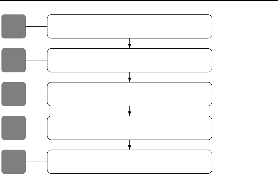
The installation follows the flow in Figure 1.
RTLS Installation Guide
Page 3/12
Physically Install RTLS Portal
ITT guides the installer through the steps of installation and connection.
RTLS Portal Auto-update
Once the portal is installed and powered up - it automatically connects the the
backend OmniTracker and gets configured without installer's involvement.
Prepare Test Tag Batch
The installer prepares a batch of test tags for SAT.
Install RTLS
Portal
15
RTLS Portal
Status
1
Perpare
Test Tag
Batch
SAT RTLS Portal
The installer perfoms SAT by running the batch of test tags through the portals
ITT creates an SAT report.
SAT RTLS
Portal
1
Test System
ITT performs a test of the system from site to backend system.
Test System
Figure 1. RTLS Installation Flow.
Read about the RTLS portal hardware in ANNEX A, e.g. product numbers and identifying the hardware parts.
Read about taking useful pictures of the installation in ANNEX B.
Read about the test tags for the installation process in ANNEX C.
RTLS Installation Guide
Page 4/12
HARDWARE DESCRIPTION
A.1. Product numbers
The following products are included in this installation guide:
- LS4510: RTLS Portal
- LS4530: RTLS Portal
- LS4550: RTLS Portal
- LS9310: Lyngsoe WiFi access point
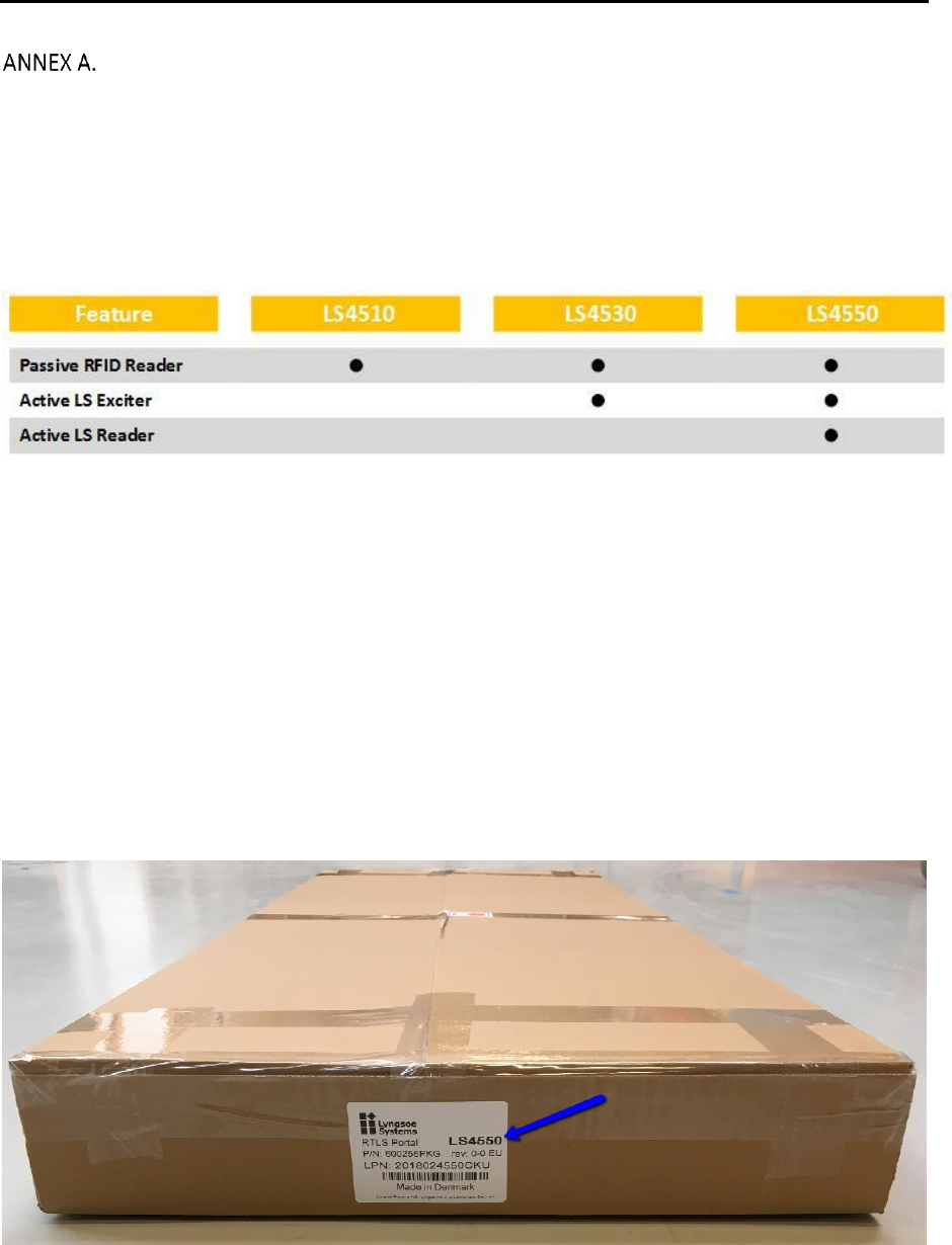
A.2. RTLS Portal versions
Figure 2. Portal features.
A.2.1. LS4510 RTLS Portal
This is a passive-only portal that incorporates a passive reader and two antennas.
A.2.2. LS4530 RTLS Portal
This is a portal that combines a passive reader with two antennas and an active low frequency exciter. This portal
will trigger active tags, but to successfully read the active tags it must be used in combination with LS4550.
A.2.3. LS4550 RTLS Portal
This is a portal that combines a passive reader with two antennas, an active low frequency exciter and an active
UHF reader. This portal can read both active and passive tags. It can also read active tags that are excited by a
nearby LS4530 portal.
A.3. Identifying RTLS portal on packing label
Figure 3. Packing label with RTLS model.
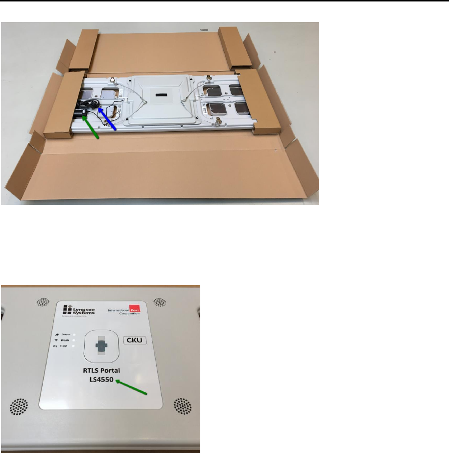
A.4. Unpacking RTLS portal – what’s in the box
RTLS Installation Guide
Page 5/12
Figure 4. RTLS portal box content with powers supply (green arrow) and power cable (blue arrow).
A.5. Recognizing RTLS models
All three models of the RTLS portals look similar on the outside. The model can be identified from the front label –
refer to the illustration below.
Figure 5. RTLS model identification
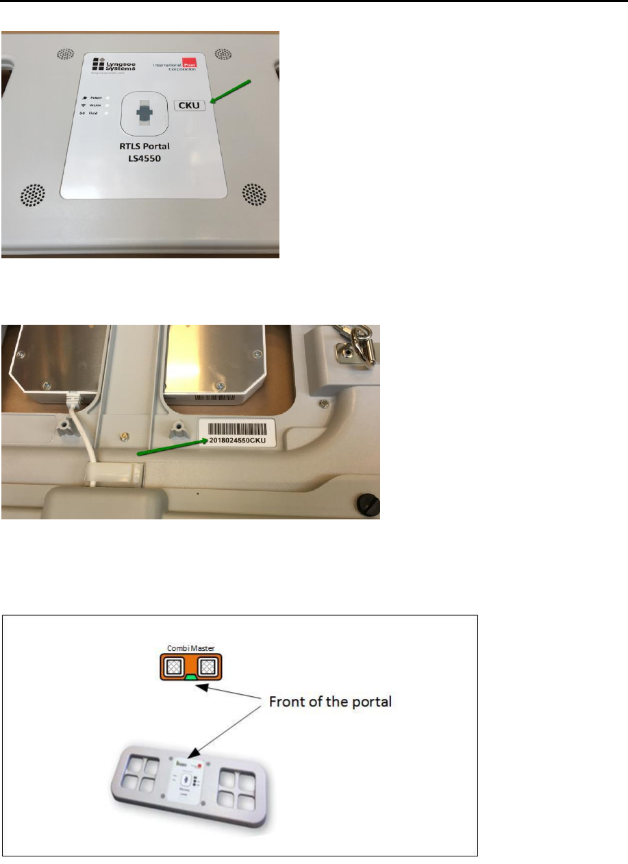
A.6. License plate
The RTLS portal is equipped with a license number. On the front the 3-character license plate number is displayed.
RTLS Installation Guide
Page 6/12
Figure 6. RTLS license plate number on front
On the back the full license plate number with barcode is placed.
Figure 7. RTLS license plate barcode on back
A.7. RTLS orientation
The RTLS portal must be mounted in a specific direction. The direction is described in the site survey with reference
to the front label and its position of the logos.
Figure 8. Portal orientation.
RTLS Installation Guide
Page 7/12
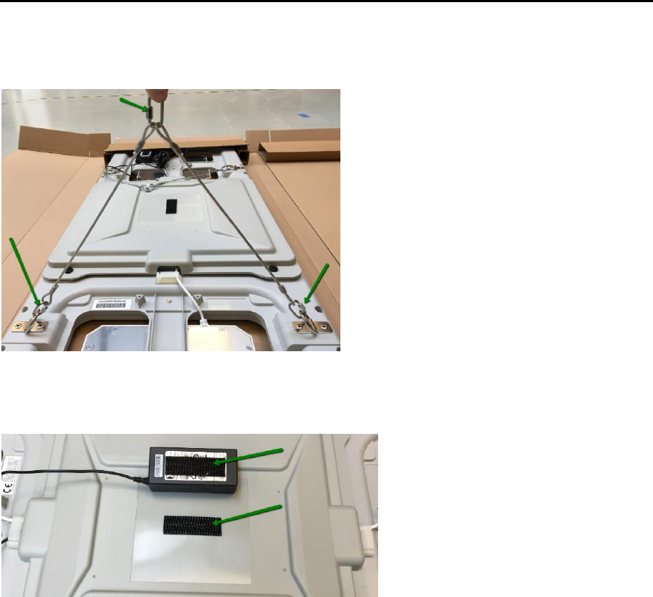
A.8. RTLS Hanging Kit
RTLS portals come with a hanging kit that consists of four flexible wires attached to the corners.
Figure 9. Portal hanging links.
A.9. RTLS power
RTLS portals come with connected power supply and power cord.
Place the power supply on the portal lid. Plug the cable into the power supply.
Figure 10. RTLS Power supply and cord
The RTLS portal is now ready for installation.
RTLS Installation Guide
Page 8/12
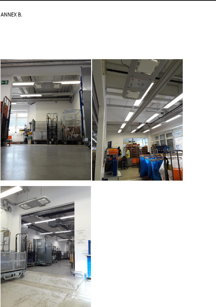
SITE PICTURES
When taking pictures of the installation it is important that the picture illustrate the equipment and the
surroundings. The purpose is both the be able to identify the portal and to see if any installations or equipment
might affect the performance of the equipment. Take more pictures, if one picture is not sufficient to document
the installation.
Good pictures:
Here three pictures of the same portal are taken from various positions.
RTLS Installation Guide
Page 9/12
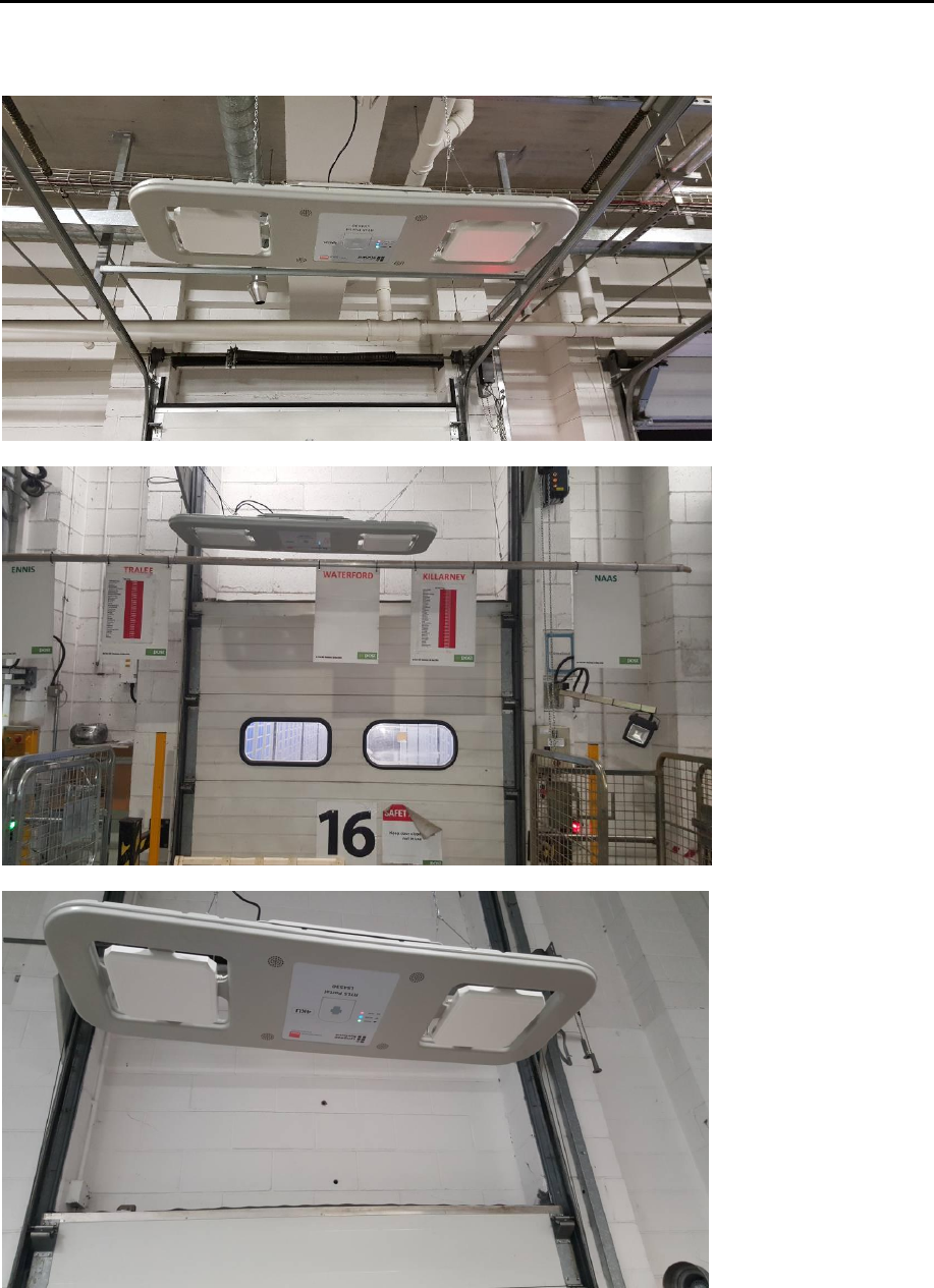
Poor pictures:
Here the surrounding e.g. the dock floor / ramp is not visible, and there is only one picture of each device.
RTLS Installation Guide
Page 10/12
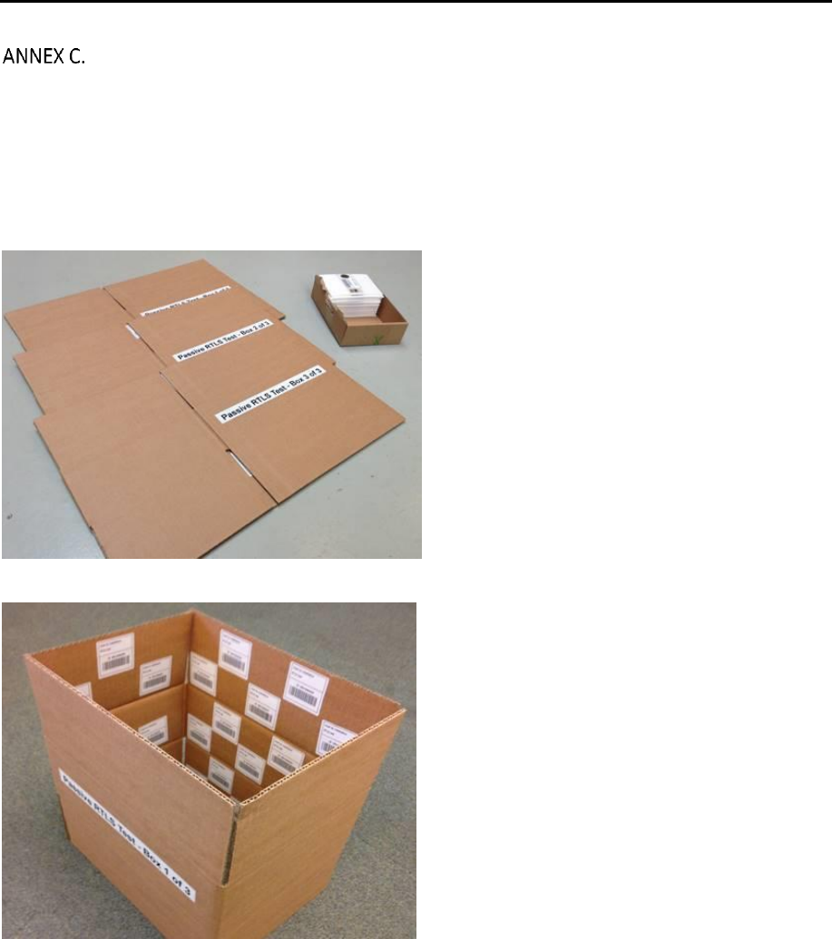
TEST TAGS
Test tags can be provided by Lyngsoe. A test tag batch is normally consisting of:
- 15 Active RFID tags
- 3 Test cartons with a total of 140 passive RFID tags.
The cartons are to be unfolded before they are used in the test and should not be placed directly on metal
surfaces.
Figure 11. cartons with passive test tags.
Figure 12. Unfolded carton with passive test tags.
RTLS Installation Guide
Page 11/12
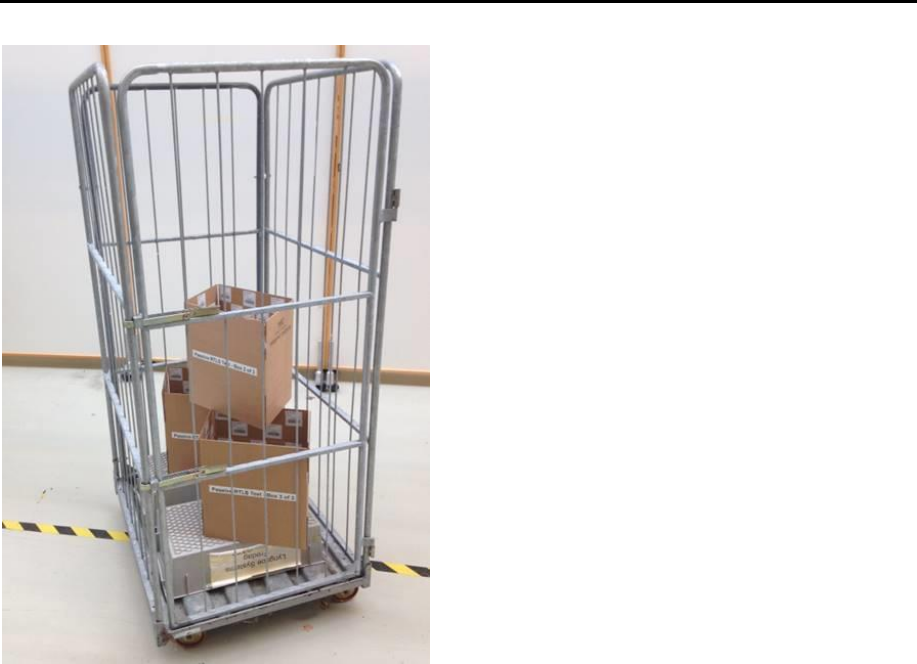
Figure 13. A roll cage with test tag cartons placed on a plastic box.
The test should be carried out as per the instruction given in the Installation and Test tool.

RTLS Installation Guide
Page 12/12
REGULATORY INFORMATION
FOR USA
Changes or modifications not expressly approved by Lyngsoe Systems could void the user's
authority to operate the equipment. During installation please follow the steps outlined in the ITT
(Installation and Test Tool).
Note: This equipment has been tested and found to comply with the limits for a Class B digital
device, pursuant to part 15 of the FCC Rules. These limits are designed to provide reasonable protection
against harmful interference in a residential installation. This equipment generates, uses and can radiate
radio frequency energy and, if not installed and used in accordance with the instructions, may cause
harmful interference to radio communications. However, there is no guarantee that interference will not
occur in a particular installation. If this equipment does cause harmful interference to radio or television
reception, which can be determined by turning the equipment off and on, the user is encouraged to try
to correct the interference by one or more of the following measures:
—Reorient or relocate the receiving antenna.
—Increase the separation between the equipment and receiver.
—Connect the equipment into an outlet on a circuit different from that to which the receiver is
connected.
—Consult the dealer or an experienced radio/TV technician for help.
FOR CANADA
This device contains licence-exempt transmitter(s)/receiver(s) that comply with Innovation, Science
and Economic Development Canada’s licence-exempt RSS(s). Operation is subject to the following two
conditions:
This device may not cause interference.
This device must accept any interference, including interference that may cause undesired
operation of the device.
L’émetteur/récepteur exempt de licence contenu dans le présent appareil est conforme aux CNR
d’Innovation, Sciences et Développement économique Canada applicables aux appareils radio exempts
de licence. L’exploitation est autorisée aux deux conditions suivantes :
L’appareil ne doit pas produire de brouillage;
L’appareil doit accepter tout brouillage radioélectrique subi, même si le brouillage est susceptible
d’en compromettre le fonctionnement.