Lyngsoe Systems PRX23 RFID READER User Manual PRX23
Lyngsoe Systems Ltd. RFID READER PRX23
USERS MANUAL

@Process RFID reader and exciter
PRX23
User Manual
Doc.# 950409 Rev. A Date: March 8, 2011
Lyngsoe Systems RFID Reader and Exciter PRX23
950409 Page 2 of 8
1. General
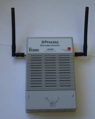
PRX23 (marketing name LS5050) is an RFID reader and exciter for Lyngsoe’s active tags
operating in the 433.92 MHz band. PRX23 (Figure 1) is used for installations in postal
applications.
Figure 1 – PRX23
PRX23 is designed to operate in a multi-drop RS485 network or on Ethernet LANs; it has
assigned a unique address. PRX23 provides the following main functions:
• Generates Lyngsoe compliant LF excitation field
• Receive over-the-air Lyngsoe tag messages
• Process received messages and send data packets with the received data to the
network over RS485 or Ethernet (with PoE option) upon request; PRX23 can also
store a number of messages in a non-volatile data memory
• Remote control/configuration using the RS485 communication network or Ethernet
• Output (on/off switchable) to power external devices such as RFID exciter
• Remote reset over the RS485 network
2. Installation
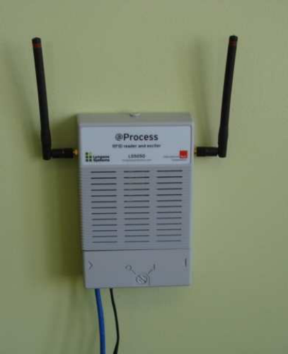
The typical installation of the PRX23 is wall mount (Figure 2). PRX23 is equipped with two
receive antennas (1/4 quarter-wave whip) for diversity.
Lyngsoe Systems RFID Reader and Exciter PRX23
950409 Page 3 of 8
Figure 2 – Typical PRX23 installation
2.1. PRX23 Connections
PRX23 has the following interfaces:
• Power
• RS485
• Ethernet
• Auxiliary power output
2.1.1. Power Connection
WARNING! Before you start the installation, check if the Power Supply provides the
specified output voltage, i.e. 24Vdc +/- 10%/0.5A.
For power connection use the 4.2mm Mini-Fit Jr receptacle (LS PN 350238) and the
female crimp terminals for AWG18-24 (LS PN 350238). Strip the wire isolation 3.0-3.5 mm
and crimp the terminals on the wire using the Molex crimping tool 11-01-0197. Insert the
terminals in the receptacle body – terminals 1 for (+24V), terminal 3 for (GND) voltage and
terminal 2 (middle) for the ground.
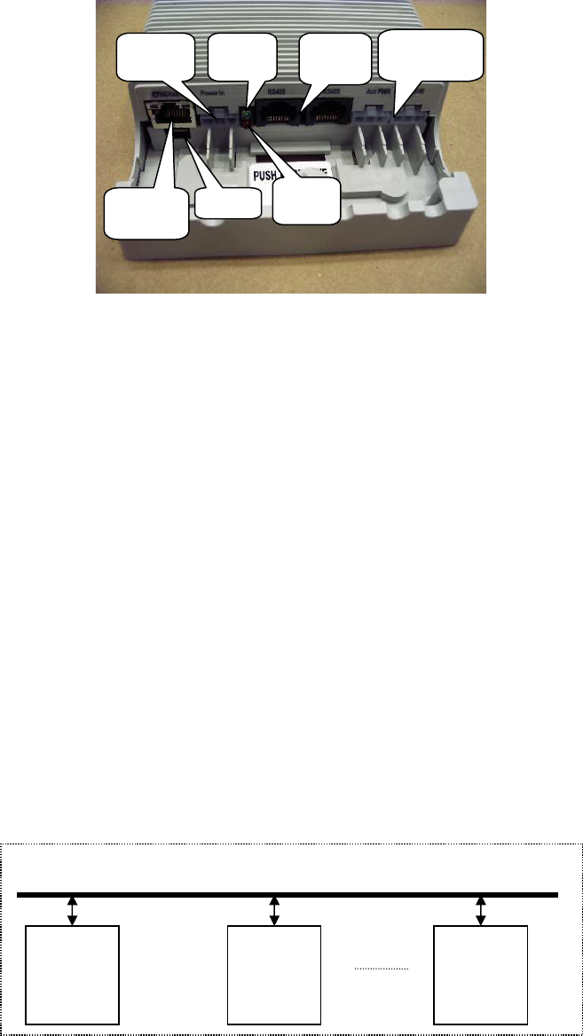
Remove the connectors cover (Figure 3) and plug in the power connector into the Power
In jack. The Power LED (green) goes ON and the Data LED (red) blinks three times
(booting). After booting, PRX23 is ready to receive over the air tag messages.
Lyngsoe Systems RFID Reader and Exciter PRX23
950409 Page 4 of 8
Figure 3- PRX23 with the connector cover removed
2.1.2. RS485 Connection
For the RS485 connection use a standard Cat5 Ethernet cable and RJ45 plug. Crimp the
connector using the recommended tool and the following color scheme: pin 1 - Wh/Or; pin
2 – Or; pin 3 – Wh/Gr; pin 4 – Bl; pin 5 – Wh/Bl; pin 6 – Gr; pin 7 – Wh /Br; pin 8 – Br.
PRX23 has a single RS485 port with two RG45 jacks connected in parallel for ease of
installation (when several PRX23 are attached to an RS485 network). Insert the RS485
connector into one of the RS485 Jacks. The default serial communications parameters
are:
• Bits per second: 19200
• Data bits: 8
• Parity: None
• Stop bits: 1
• Flow Control: None
Up to 99 PRX23s can be connected to an RS485 serial bus (Figure 4). Each reader has its
own serial address.
Figure 4 – PRX23 on RS485 network
Controller
PRX23
Address=1
PRX23
Address=n
(n<100)
RS485 bus
Power
In Jack
Ethernet
Port
RS485
Jacks
Aux. Power
Outputs
Data
LED
Power
LED
USB

Lyngsoe Systems RFID Reader and Exciter PRX23
950409 Page 5 of 8
The operation of the PRX23 reader is controlled by commands and parameters. The
commands and parameters are passed to the PRX23 reader by a computer running a
serial communication application such as Procomm. There are several specific
commands to configure or to query the PRX23 parameter values. Each command starts
with an address field. The commands are described in details in the RFID System S23
Reference Guide document.
2.1.3. Ethernet Connection
PRX23 is equipped with a 10/100 Ethernet port for LAN connection. The default mode is
AutoDetect. The port also supports the HP Auto-MDIX mode. The Ethernet port
connection use a standard RG45 jack. All the commands and parameters available on the
PRX23 can use either static IP address (default) or dynamic IP address. The IP address
has to be set using the USB console. PRX23 uses a UART-to-USB converter (FT232R).
When PRX23 is connected to the USB port of a computer for the first time, one needs to
install the VCP driver for the FT232R device from http://www.ftdichip.com/FTDrivers.htm.
After downloading the driver, plug one end (micro B) of the USB cable into the USB port
(located under the ETHERNET port, see Figure 3) of the Reader and the other end into a
computer USB port. The USB serial port settings are:
• Bits per second: 19200
• Data bits: 8
• Parity: None
• Stop bits: 1
• Flow Control: None
Before setting the IP address, the subnet Mask and the Gateway need to be set. From the
USB console, type INM=”x.x.x.x” and press Enter, where x.x.x.x is the Subnet Mask. You
should see:
OK
INM=”x.x.x.x”
If you see ERROR, try again.
Type IGW=”x.x.x.x” and press Enter, where x.x.x.x is the Gateway. You should see:
OK
IGW=”x.x.x.x”
Type :CONFIG:STORE and press Enter to store these configuration. You should see:
OK
00
a. Set a static IP address
Lyngsoe Systems RFID Reader and Exciter PRX23
950409 Page 6 of 8
To assign a static IP address, type IIP=”x.x.x.x” where x.x.x.x is the IP address, and
press Enter. You should see
OK
IIP=” x.x.x.x”
Type :CONFIG:STORE and press Enter, to store the new IP address. You should see:
OK
00
Then, type :RESET and press Enter. You should see:
PRX23, Lyngsoe Systems Ltd. (c)
b. Use DHCP to get an IP address
Make sure the network cable is connected. Type IDH=Y and press Enter to select
“dynamic IP mode”. You should see:
OK
IDH=Y
Type :CONFIG:STORE and press Enter. You should see;
OK
00
Type :RESET and press Enter. You should see
PRX23, Lyngsoe Systems Ltd. (c)
Type IIP and press Enter to read the IP address. You should see:
OK
DHCP IP Address: x.x.x.x
where x.x.x.x is the IP address assigned to the PRX23. If the PRX23 power is cycled, the
dynamic IP address may change.
After the IP address has been set, the reader is ready to communicate over Ethernet; for
testing, you can use Hyper Terminal again. To do this, follow the steps below:
3. Operation
Every time a tag message is received it will be shown on the RS485 or Ethernet console if
the tag dumping function is enabled. The following is an example:
{TS="0905191637Z",LI=-62,UD="C\xFD\x00\x08\x02",EX="\x7F",CT="\x00",FG="HI"}
Lyngsoe Systems RFID Reader and Exciter PRX23
950409 Page 7 of 8
Where:
TS="0905191637Z" is the time the tag is received
LI=-62 indicates the RSSI level of the tag signal in dBm
UD="C\xFD\x00\x08\x02" is the user data of the tag
EX="\x7F" is the Exciter ID (when applicable)
CT="\x00" is the programmed CTRL byte
FG="HI" indicates the tag battery level. H means battery is OK. If the battery is low, this
field will show “Lx” where x depends on the tag type.
Type DAR=N and press Enter to stop dumping tag data. You should see:
OK
DAR=N
Type DAR=Y and press Enter to start dumping tag data. You should see:
OK
DAR=Y
If the
user does not want to automatically dump the data, the commands used to
query the reader are described in the
RFID System S23 Reference Guide document.
Lyngsoe Systems RFID Reader and Exciter PRX23
950409 Page 8 of 8
Regulatory Compliance:
This device complies with Part 15 of the FCC Rules,. Operation is subject to the following
two conditions: (1) this device may not cause harmful interference, and (2) this device
must accept any interference received, including interference that may cause undesired
operation.
Any changes or modifications of this product, not approved by manufacturer will void the
user’s authority to operate the equipment.
This device complies with Industry Canada license-exempt RSS standard(s). Operation is
subject to the following two conditions: (1) this device may not cause interference, and (2)
this device must accept any interference, including interference that may cause undesired
operation of the device
Le présent appareil est conforme aux CNR d'Industrie Canada applicables aux appareils
radio exempts de licence. L'exploitation est autorisée aux deux conditions suivantes : (1)
l'appareil ne doit pas produire de brouillage, et (2) l'utilisateur de l'appareil doit accepter
tout brouillage radioélectrique subi, même si le brouillage est susceptible d'en
compromettre le fonctionnement.