Lyngsoe Systems XR30 RFID Rd/Ex XR30 User Manual 950213
Lyngsoe Systems Ltd. RFID Rd/Ex XR30 950213
User Manual

Lyngsoe Systems RFID Rd/Ex XR30
950213-.doc Page 1 of 5
RFID Rx/Ex XR30
User Guide
Revision - – August 07, 2009
Lyngsoe Systems RFID Rd/Ex XR30
950213-.doc Page 2 of 5
1. General
RFID Rd/Ex XR30 is basically an RFID Exciter EX30 which incorporates also a Reader
RD23. It can operate as an RFID Exciter and Reader to excite RFID Tags and to receive
their UHF messages.
RFID Rd/Ex XR30 as a combined unit provides all the functionalities documented for the
EX30 and RD23 units. These functionalities and technical specifications are completely
described by the following documents:
- RFID Exciter EX30 User Guide - doc 950212-.pdf;
- Exciter Board EXB30, Functional Specification – EXB30FSrC.pdf;
- RFID Reader RD23, User Guide – doc. 950214-.pdf;
- RFID System S23, Reference Guide – doc S23ReferenceGuide.pdf;
- Reader RD23, Technical Specification – doc RD23Description-IC.pdf
The marketing name for XR30 is LS4000 – this name is printed on the front label.
2. Installation
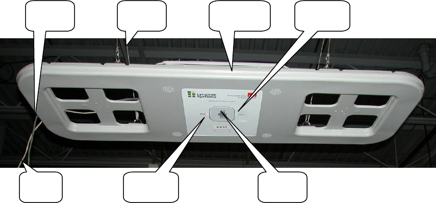
Installation of the XR30 unit is quite similar with the description provided for the Exciter
EX30 and RD23. Typical installation of the XR30 is presented in the figure 2-1; all the
external connections are accessible inside the unit as presented in figure 2-2.
Figure 2-1 Exciter EX30 installation
2.1. EX30 Connections
Power Connections
WARNING! Before you start the installation, check if the Power Supply provides the
specified output voltage – 24Vdc +/- 10%, and min. 1A; for the power connections use the
4.2mm Mini-Fit Jr receptacle (LS PN 350238) and the female crimp terminals for
AWG18-24 (LS PN 350238). Strip the wire isolation 3.0-3.5 mm and crimp the terminals
on the wire using the Molex crimping tool 11-01-0197. Insert the terminals in the
EX30
Power
Cable
RS485
Cable Power
ON LED
Field ON
LED Motion
Senso
r
Isolated
Chains
Lyngsoe Systems RFID Rd/Ex XR30
950213-.doc Page 3 of 5
receptacle body – terminals 1 for (+24V), terminal 3 for (GND) voltage and terminal 2
(middle) for the ground.
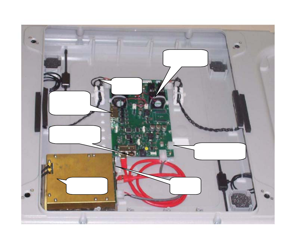
Remove the cover. Plug in the power connector into any of the corresponding headers on
the RDS230. The POWER LED (green) goes ON.
Fig 2-2 Connectors location for XR30
Exciter Board
EXB30
Power
connecto
r
RS485 connectors
for network control
RS485
connectors for
master/slave
24Vdc power
to other Exciters
Ext 24V
Power
Reader Assy.
RDS23
Lyngsoe Systems RFID Rd/Ex XR30
950213-.doc Page 4 of 5
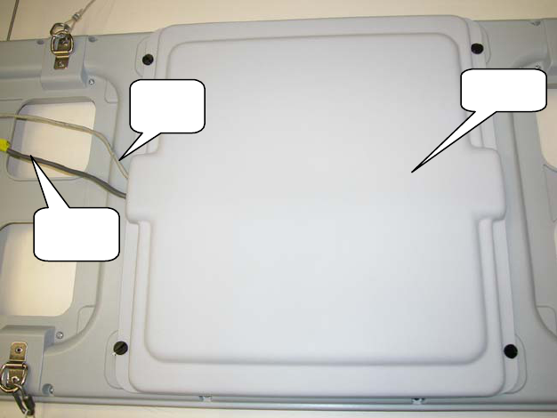
Fig 2-3 Cover installation for XR30
RS485 Connections
For the RS485 connection use a standard Cat5 Ethernet cable and RJ45 plug. Crimp the
connector using the recommended tool and the following color scheme: pin 1 - Wh/Or; pin
2 – Or; pin 3 – Wh/Gr; pin 4 – Bl; pin 5 – Wh/Bl; pin 6 – Gr; pin 7 – Wh /Br; pin 8 – Br.
Insert the RS485 connector as in Fig.2-2. Close the cover as in Fig. 2-3.
2.2. PC Software Configuration
The simplest way to control XR30 is by using a Terminal Emulation program on the PC. The
general configuration procedure consists of:
• Open a Terminal Emulation program on your computer (Procomm, HyperTerminal, etc).
• Configure the computer’s COM port to which the XR30 is connected. The default configuration
for the COM port is: COM port - COM1; Data rate - 19200 bps; Data bits - 8 bits; Parity – none;
Stop bits – 1; Flow control – none.
• Use an adapter from USB to RS485 (LS PN 600057) if only USB ports are available on the PC.
• From the PC send commands to XR30 and observe the responses on the PC.
Other dedicated software can be used to control XR30 as long as the correct commands are
provided for XR30, as documented.
3. Operation
3.1. Remote control
The operation of the XR30 is controlled by commands and parameters. The parameters values are
set into XR30 during the configuration session. This configuration is controlled by a PC running
Cover
Power
Cable
RS485
Cable
Lyngsoe Systems RFID Rd/Ex XR30
950213-.doc Page 5 of 5
serial communication program like Procomm, through a serial communication link type RS485.
There are several specific commands to configure or to query the XR30 parameters values.
XR30 has a unique address called NetId. The NetId is an integer in the range 0 to 127 and is a good
practice to clearly mark it on the front label in the designated area.
Readers can be controlled using the syntax:
@NetId <space><COMMAND> <CR>; the prefix #NetId is separated from the command itself
by a space.
Exciters can be controlled using the syntax:
#NetId <space><COMMAND> <CR>; the prefix #NetId is separated from the command itself
by a space.
4. Commands and Parameters
For the complete list of commands and parameters accepted by the Exciter see documentation for
Exciter EX30, and for the Reader see documentation of Reader RD23.
FCC compliance
Caution:
Changes or modifications not expressly approved by the party responsible for compliance could
void the user’s authority to operate the equipment.
Part 15.105 Information to the user
NOTE: This equipment has been tested and found to comply with the limits for a Class B digital
device, pursuant to part 15 of the FCC Rules. These limits are designed to provide reasonable
protection against harmful interference in a residential installation. This equipment generates, uses,
and can radiate radio frequency energy and, if not installed and used in accordance with the
instructions, may cause harmful interference to radio communications. However, there is no
guarantee that interference will not occur in a particular installation. If this equipment does cause
harmful interference to radio or television reception, which can be determined by turning the
equipment off and on, the user is encouraged to try to correct the interference by one or more of the
following measures:
—Reorient or relocate the receiving antenna.
—Increase the separation between the equipment and receiver.
—Connect the equipment into an outlet on a circuit different from that to which the receiver is
connected.
—Consult the dealer or an experienced radio/TV technician for help.