M Labs Technologies LN01A GPS Tracker User Manual
M-Labs Technologies, LLC GPS Tracker User Manual
User_Manual

© 2018 M-Labs Technologies LLC
1/15
User
Manual
LN-L
Lioness-L
Tracking Device
May 21, 2018
R1.0
Theinformationpresentedinthisdocumentisstrictlyconfidentialandcontainstradesecrets and
otherconfidentialinformation that are the exclusive propertyof M-Labs Technologies,LLC.
© 2018 M-Labs Technologies LLC
2/15
Author
Revision
Changes
Date
1.0
Initial version
2018 Apr 26
© 2018 M-Labs Technologies LLC
3/15
Contents
1 Introduction ........................................................................................................................................ 4
2 HardwareDesign ............................................................................................................................. 5
2.1 Basic Hardware ...................................................................................................................... 5
GPS .................................................................................................................................................. 6
GPIO ................................................................................................................................................ 6
LED’s ................................................................................................................................................ 6
UART ............................................................................................................................................... 6
USB .................................................................................................................................................. 6
RelayDriver ...................................................................................................................................... 6
Power and Battery .......................................................................................................................... 7
Timers ............................................................................................................................................. 7
Watchdog ........................................................................................................................................ 7
Accelerometer ................................................................................................................................ 7
2.2 Basic RF Performance .................................................................................................................. 7
2.3 Certification andSafety ........................................................................................................... 9
3 SoftwareFeatures .......................................................................................................................... 11
3.1 Basic Software ...................................................................................................................... 11
3.2 Remote Update .......................................................................................................................... 11
3.3 PowerModes .............................................................................................................................. 11
3.4 AT Commands ........................................................................................................................... 12
3.5 Ack’ed Mode ............................................................................................................................. 12
3.6 Event Report Format ................................................................................................................. 12
3.7 Reset .......................................................................................................................................... 12
3.7.1 Context Preservation ........................................................................................................... 13
3.8 Startup Banner ........................................................................................................................... 13
4 TestMethod ................................................................................................................................... 14
4.1 Hardware .............................................................................................................................. 14
4.2 Software Test ........................................................................................................................ 14
MechanicalStructure (mm) ................................................................................................................... 15
FCCStatement ....................................................................................................................................... 16
RFExposureWarningStatements: .......................................................................................................... 16
ICSTATEMENT ........................................................................................................................................ 16
© 2018 M-Labs Technologies LLC
4/15
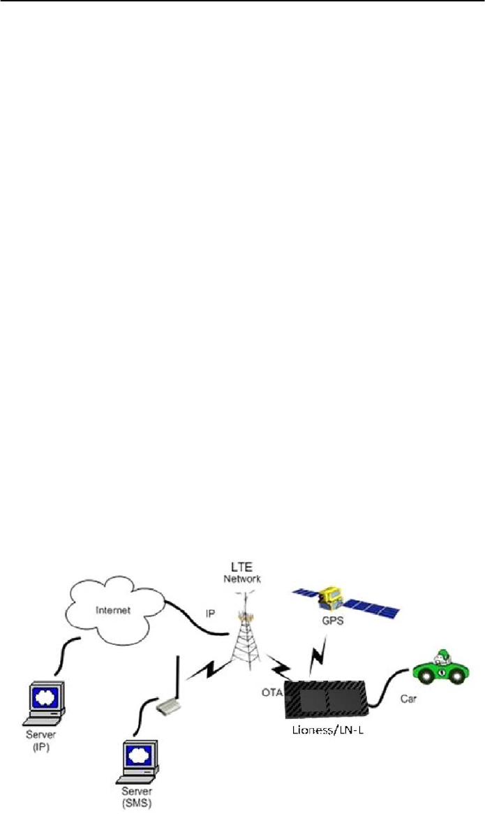
1 Introduction
TheLN-Lisaself-containedvehicletrackingdevicethatcombinesGPSlocationwithLTECAT1/3G
fallbackcellular connectivity. It is primarily a location reporting device that responds to requests
(user, server) and events (timers, geo-fences). Data reports consist of a single record that
contains all location data and system status.
The device comes pre-configured from the factory. It is ready to use. TheLN-
Lappearstoauseroraserverapplicationasanendpointdevice.Itcan
bequeried,updatedandconfiguredeitherthroughaserialconnection, anovertheairIP connection,
orthroughSMSmessaging.TheLN-Lpresentsitselfoverthese
connectionsasanenhancedcellularmodemwithattachedfunctionalelements.Theseelements
include:
• GPSlocationengine
• Accelerometer
• Input/outputs dedicated for ignition, relay, buzzer, and general purpose
• SerialUARTport
• Timers
• Watchdoglockupprotection
• Power management
• Event reporting
• Voltage monitoring
AccesstotheseelementsandgeneralpurposeinterfacesisdonethroughanextendedAT
command set. Configuration parameters are stored to flash memory and are automatically
used on the next power up event. For more details, please reference the AT Command
document.
Figure 1

© 2018 M-Labs Technologies LLC
5/15
ThisproductisdesignedbasedontheQuectel EC21-A(4GLTE CAT 1/3G fallback,
)b
asebandmodule.
Antennas for cellular and GPS are internal to the device.
2 HardwareDesign
2.1 Basic Hardware
Items
Requirement
Cellular Modem
Based on Quectel EC21-A baseband module.
Cellular Network Interface
Support for LTEB12, B4, B2 WCDMA B2, B4, B5
Frequency
B2(MHZ):TX(1850-1910) RX(1930-1990)
B4(MHZ): TX(1710-1755) RX(2110-2155) B12(MHZ):
TX(699-716) RX(729-746)
B5 (MHZ): TX (824-849) RX (869-894)
Cellular Antenna
Internal single antenna
GPSAntenna
Dedicate high performance ceramic antenna
UIMrequirement
Support: 3FF SIM Interrupt Mode
No Support:Hot Plug/Unplug
BatteryMonitor
Internal analog input
Buildinbatterymanager Yes
Interface
Debug UART
Application UART
USB
12V DC Input(1A current), Ground
Relay Drive (Open Drain ,500mA current)
Dedicated Output for buzzer control
Ignition Input
GPIO
DedicateTimers
Yes
Watchdog
External HW via MCU
MotionDetect
Supported(GPS/G-Sensor)
LED
2 LED Supported
1- RED; 1- Green
Battery
Build in battery(80MAH Lion)
WorkingTime
4 hours
Powerswitch
No
PowerCablecolor
8 colors
PowerCableconnectortype
8-pin connector
PowerConsumption
< 5Watts
TheLN-
LprovidessupportforspecializedhardwarefeaturesthroughextendedATcommands.Thefeaturessup
portedincludethefollowing:

© 2018 M-Labs Technologies LLC
6/15
GPS
GPS location functionality is provided by the device GPS receiver. NMEA GPS records can be
extracted in real time from the unit via the UART connection using special debug commands
that are outside the scope of this document.
GPIO
One dedicated input, two dedicated outputs, and one general purpose IO are
presentedtotheexternal
environment
onthemainconnector. Theyare
capableofprovidingsysteminterruptstogenerateareport ordrive logiclevels
toexternaldevices.These lines are2.8Vlogiclevelandare16V tolerant.Thesepinsdefaulttoinputand
arepulleddownrepresenting 0whendisconnected.Theyshouldbeassertedtoaknown valueifused.
LED’s
TwoLEDstatusindicatorsareprovidedto verifycorrectinstallationandoperation.Thestatus
LEDsarecolorcodedanddirectlyconveythestatusofthecellularandGPSsubsystems as
describedinthetablebelow.Theirvalidoperationalsoindicatesoperationalstatusandpower.
LED
Function
Status
Red
GPS
On:GPSsatellitesacquiredandLocked
FlashSlow:GPSsatellitesearchisinprogress
Off:NopowerorGPSsubsystemfault
Green
Cellular
Connection
On:IndicatesLTEconnectionismade
FlashSlow:LTEsubsysteminitialization in progress
FlashFast:LTE initialization but no data connection available
Off:NopowerorLTEsubsystemfault
TheLN-LprovidesusercontrolallowingtheLEDstobeextinguishedonceinstallation
isverified.ThisfeaturereducespowerandfurtherconcealstheLN-LTrackerfrom
untrainedpartieswishingtodefeatitsoperation.
UART
There is one UART’s provided. A debugUARTportis providedforATcommands,datainteraction
andoptionallyforapplication specificcontrol.
USB
The USBportis providedforprovisioning or debug available only if the case is open.
RelayDriver
A500mAsinkcapableoutputpinisprovided.Thispinismeant todrive arelaycoilindented
tointerruptthestartersolenoidrelayfortheignitioncircuittoacar.

© 2018 M-Labs Technologies LLC
7/15
Power and Battery
Thebatterymonitor isinternalanaloginputscaledsuchthattheDCvalueofthepowerinput
pintotheLN-Lsystemis measured.Thisvalueisscaledtospanthemostsignificant8
bitsoftheA/Dandconsequentlycoversascalefrom0 to28Volts.
Timers
Timersresidentonthebasebandchipgenerateperiodicinterrupts forpowerdownwakeup,
watchdogsupport,periodic reportgeneration andothertimerrelatedfunctions.
Watchdog
Quectel EC21-AchipsetprovidesinternalsoftwareWatchdog. Also the LN-
LincludesanMCUthatactsasafailsafeexternalwatchdog.TheMCUpowercycles thesystem,if
noactivityisdetectedfor1 hour.
Accelerometer
The accelerometer can be used for motion detection and driver behavior monitoring.
2.2 Basic RF Performance
Items Requirements
Remark
TRPfree space LTE B2: channel 650: 20.7dBm
channel 900: 20.38dBm
channel 1150: 20.76dBm
LTE B4: channel 200: 20.7dBm
channel 2175: 20.53dBm
channel 2350: 20.53dBm
LTE B12: channel 5060: 20.3dBm
channel 5095: 20.1dBm
channel 5130: 20.3dBm
TRPfree space
TIS free space
Main: LTE B2 : -94.47dBm
LTE B4: -94.4dBm
LTE B12: -94.8dBm
DIV: DNP
TIS free space

© 2018 M-Labs Technologies LLC
8/15
Antenna loss LTE B2: channel 650: -3.1dBm
channel 900 : -3.2dBm
channel 1150: -3.1dBm
LTE B4: channel 200: -3.2dBm
channel 2175 : -3.1dBm
channel 2350: -3.2dBm
LTE B12: channel 5060: -4.3dBm
channel 5095: -4dBm
channel 5130: -3.7dBm
TRP-TX Power Conducted
Antenna Loss
Main: LTE B2 : -5.5dBm
LTE B4: -5.5dBm
LTE B12: -5.2dBm
DIV: DNP
RXreceivesensitivitycond
ucted– TIS
BoardRFSpecification
LTE_B4RX
B4Frequencyrange
2110-2155MHZ
Sensitivity
-99.5dBm(10MHZ_50RB_Downlink)
Dynamicrange
-23
~
-99.5dBm
LTE_B4TX
B4Frequencyrange
1710MHz~1755MHz
MaximumFrequencyerror
±10Hz
Maximumoutputpower
23dBm
Minimumcontrol output power
<-40dBm
ACLR UTRA2:46.48 UTRA1: 41.21 E-UTRA1:39.23
UTRA2:43.87 UTRA1: 40.51 E-UTRA2:38.05
OBW
8.87MHZ(10MHZ Nominal)
IQOFFSET
<-55.6dbc
EVM <3%
LTE_B12_RX
Frequency range
728MHz~ 746MHz
Sensitivity
-100dBm(10MHZ_50RB_Downlink)
Dynamicrange
-23~ -100dBm
LTE_B12_TX
Frequency range
698MHz~ 716MHz
MaximumFrequency error
±10Hz
Maximumoutputpower
23dBm
Minimumcontrol output power
<-40dBm
ACLR UTRA2:45.48 UTRA1: 41.41 E-UTRA1:39.43
UTRA2:44.87 UTRA1: 41.51 E-UTRA2:38.25
OBW
8.87MHZ(10MHZ Nominal)
IQOFFSET
<-54.7dbc
© 2018 M-Labs Technologies LLC
9/15
EVM
<3%
LTE_B2_RX
Frequency range
(1930-1990)MHZ
Sensitivity
-100dBm(10MHZ_50RB_Downlink)
Dynamicrange
-23~ -100dBm
LTE_B2_TX
Frequency range
(
1850-1910
)
MHZ
MaximumFrequency error
±10Hz
Maximumoutputpower
23dBm
Minimumcontrol output power
<-40dBm
ACLR UTRA2:46.48 UTRA1: 41.51 E-UTRA1:39.49
UTRA2:44.45 UTRA1: 42.51 E-UTRA2:38.29
OBW
8.87MHZ(10MHZ Nominal)
IQOFFSET
<-54.9dbc
EVM
<3%
GPS
Frequency Support
L1-band(1.57542GHz)
Channels: 210PRN,66Search,22Simultaneous
tracking
Sensitivity
Sensitivity(UHIS):
Tracking:-156dBm
Reacquisition:-153dBm
Acquisition:-144dBm
TrackingTime Requirement
Acquisitiontime:
Hot:<2s
Warm:<15s
Cold:<60s
Reacquisition:2s-10sDependsonsignallevel
2.3 Certification andSafety
Items
Requirement
Drop Design
1.2meter 6direction standard drop test
Temperature Range
-20to40°COperation
-50to +100°C Storage
Humidity: 20% to90% Operation
10% to95%Storage
Altitude:
-500 to +18,000m
VehicleISOTest
ISO7637-2-2004;ISO7637-3-2007;ISO10605-2008;
ISO16750-2-2010
FCC Certification
FCC 47 CFRPart 15 and Part 18
OtherCertifications
Industry Canada(optional)
ESD Requirement
10KVnon-Conductive
OperatorCertifications
PTCRB / AT&T

© 2018 M-Labs Technologies LLC
11/15
3 SoftwareFeatures
3.1 Basic Software
Items
Requirement
Network Interface
LTE B2, B4, B12 WCDMA B2, B4, B5
IPStack
IPV4/IPV6
UpgradeMethod
Remoteupdate/PCtool
RemoteUpdate
Supported – including OMA DM
PowerModes
Supported
ATCommands
Supported
Report
Supported: 3000records
Drivers
GPIO
,
LED
,
GPS
,
UART, USB Accelerometer
GPIOs
InterruptforIgnitionStatus, Buzzer, Relay
LEDs
GPSStatus,NetworkStatus
WatchDog
Supported
Reset
Softreset,hardreset, GPS reset, RF reset
StartupBanner
Supported
3.2 Remote Update
TheLN-LsupportsOTAfieldupgradesoftheresidentapplication.An
overtheair
TFTP
(TrivialFileTransferProtocol)connectionismadeovera
n IP
connection.
Areplacementfileisthentransferred fromaservertotheLN-Landthatfilereplaces
thepreviousapplicationimage.
3.3 PowerModes
TheLN-L devicesupportsseveralpowermodesthataresetbyAT commands.
InfullpowermodetheGPSisactiveandthecellularsubsystem willmaintaina
persistentcellularconnectionwheneverserviceisavailable.IPconnection ismaintained
accordingto theconfigurationofthedevice.
Thedevicecanbeputinlowpowermodewheneveritrunsonabackupbatteryoriftheexternal
batteryis loworifitis notmoving.InlowpowermodetheGPSisnot runningand theLED’s
areoff.Thedevicewouldreturntofull powerwheneveraneventoccursthattriggersareport.
Thoseeventsinclude:
• Periodic report
• GPIO change
• IP change
• Battery threshold
• Heartbeat
• Watchdog
© 2018 M-Labs Technologies LLC
12/15
• Power-up
• Ignition
• Trip start and stop
Anyhardwareorsoftwareresetwillreturnthedevicetofullpowermode.
3.4 AT Commands
Extended AT commands are specific to the LN-L device. They are closely based on commands
that are as similar as possible industry common devices and are essentially subsets of standard
LN-L commands. Native AT commands supported by the Quectel EC21-A modules are also
available via the serial and USB interfaces.
3.5 Ack’ed Mode
UDPisnota100%reliableconnectionandoccasionalreports orcommand/responsesmaybe
lost.Sinceallcommandshaveresponses,theservercanrepeatanycommandto whichthereis
noresponse.Inordertoassurereliablereceptionofreports,LN-Ldevicescanbeconfigured
eitherinNormalorAck’edmodetosendthereports.IntheNormalmodethereportsaresimply
sent“asis” withnoacknowledgmentfromtheserver.IntheAck’edmodeeveryreportsentis
expectedtobeacknowledged bytheserverbysendingbackanACKmessageback.If
acknowledgement
isnotreceivedwithinthespecifiedtimeout,thereportisre-sent.Ifthereport
isnotacknowledgedafterthespecifiednumberofattempts,itisqueued.Ifacknowledgement
isreceivedafterthereportisqueued(i.e.pasttimeoutofthelastattempt),itisignored.
Report is not considered “complete” until its acknowledgement is received. Thus, if report X is
sent and report X+1 is triggered while waiting for acknowledgement of X, report X+1 will be
queued until such acknowledgement is received and only then sent. The LN-L will attempt to re-
send queued report(s) every time a new report is triggered. If there is more than one report
queued, the reports will attempt to be sent in the order of triggering and only once the report
is acknowledged, the next report is attempted. This assures that reports are sent and received
in order
Ack’edmodeassuresthatallreports arereceived,butaddsoverheadintimeanddata.Report
thatisnot
acknowledged
issentagainand
eventually
willbequeuedandsentagain.Thenumber
andfrequencyofre-triesisconfigurableviatheReportAcknowledgement command.
3.6 Event Report Format
Reportsareencoded as binaryhex.It is also echoed to the debug UART in ASCII format.
3.7Reset
Thereareanumberofresetsavailableonthedevice.Softresetonlyrestartsthesoftware
runningonthedevice.Hardresetiscausedbyresettingthewholebasband moduleviaareset
© 2018 M-Labs Technologies LLC
13/15
pin.ThereisalsoanoptiontoresettheGPSand the cellular sub-systemsindividually.
3.7.1 Context Preservation
Whenaself-initiated resetisperformeddue toNetworkWatchdog orbytheResetcommand
(modes0,1),the
contextofthesystemisbeingpreservedandisrestoredafterthereset.Thecontextincludesall
theperiodictimers,thereportqueue,theodometer,etc.Thisallowstoresettheunitasa
troubleshooting
or preventive
measurewithoutlosingreports
thatarealreadyinthequeueorarependingonrunningtimers.Notethattheresetprocessmay cause1-
2minofinaccuracyinthetimersandshouldnotbeconsideredasveryprecise.
3.8Startup Banner
AfteraresetastartupbannerisprintedthroughtheUARTonly.

© 2018 M-Labs Technologies LLC
14/15
4 TestMethod
4.1 Hardware
Test Item
Description
Baseband FunctionTest
• Power InputTest
• Power Consumption and CurrentTest
• Heat DissipationTest
• UARTStabilityTest
• GPIOLevelTest
• LED StabilityTest
• DropDownTest
• ESDTest
• High/LowTemperatureTest
• HumidityTest
RFTest • RF PerformanceTest
• GPS PerformanceTest
• Antenna PerformanceTest
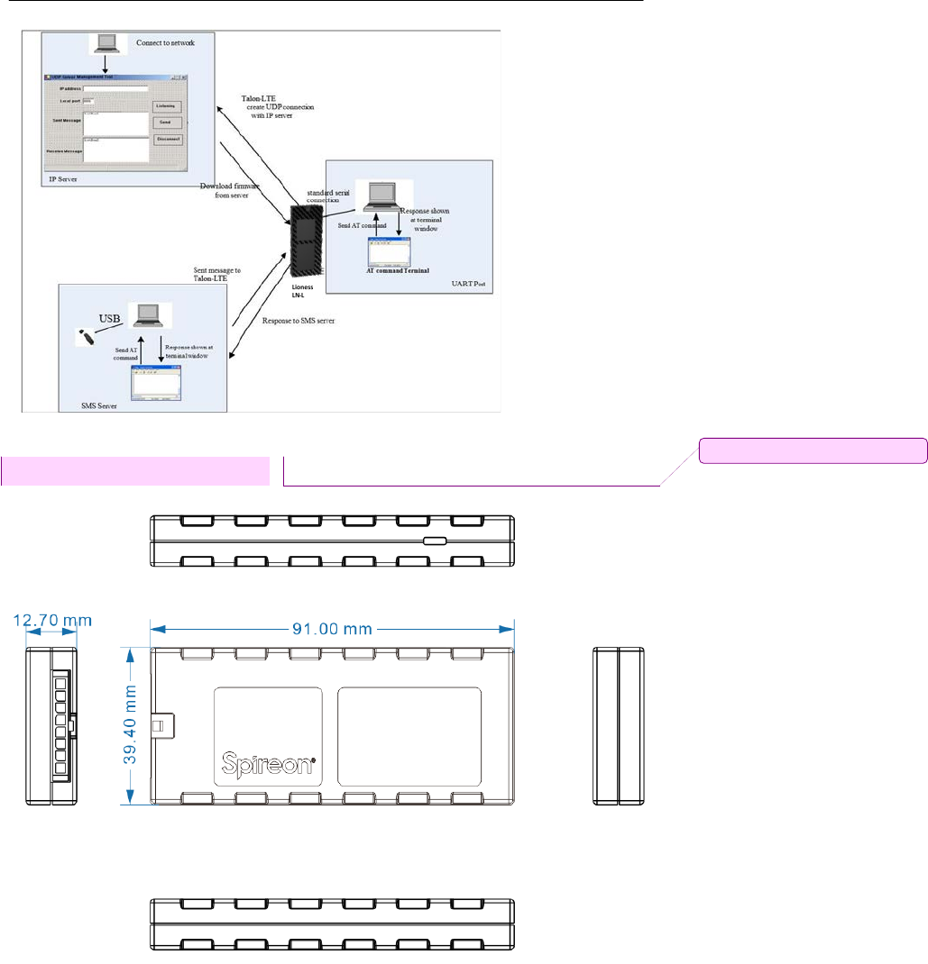
4.2 Software Test
TestEnvironmentConstruct
MessageTestenvironment
1.USBdongleandPCasmessageserver
2.SendmessagetoLN-L
UDPTestenvironment
1.ConnectdongletoPCandcreatedialupasipserver
2.LN-LcreateIPconnectiontoserver
UARTTestenvironment
1.ConnectLN-LtoPCwithcomserialcable
2.OpenTerminaltoolandsendatcommand
3.Responsecanbeshownatterminalwindow
© 2018 M-Labs Technologies LLC
15/15
MechanicalStructure (mm)
批注 [GE1]: Needs update

© 2018 M-Labs Technologies LLC
16/15
FCCStatement
This equipmenthas beentestedandfoundtocomplywiththe limitsforaClass Bdigitaldevice,
pursuanttoPart15oftheFCCRules. Theselimitsaredesignedtoprovidereasonableprotection
againstharmfulinterferenceinaresidentialinstallation. Thisequipmentgeneratesusesandcan
radiateradiofrequency energyand,ifnot installedandused inaccordancewiththeinstructions,
maycauseharmfulinterferencetoradiocommunications.However,thereisno guaranteethat
interferencewill notoccurinaparticularinstallation.If thisequipmentdoescauseharmful interference to
radioortelevisionreception,which canbe determined by turning theequipment off and on, the
userisencouragedtotry tocorrecttheinterferencebyoneormoreofthefollowing measures:
-- Reorient orrelocatethe receivingantenna.
-- Increase theseparation betweentheequipment andreceiver.
--Connecttheequipmentinto anoutlet onacircuitdifferentfrom thattowhich thereceiveris connected.
-- Consult thedealer oran experienced radio/TVtechnician forhelp.
Thisdevicecomplieswithpart15oftheFCCRules. Operationissubject tothefollowingtwo conditions:
(1)Thisdevicemaynotcauseharmfulinterference,and(2)thisdevicemustacceptanyinterference received,
including interference that may cause undesired operation.
Changesormodificationsnotexpresslyapprovedbythepartyresponsiblefor compliancecould void
theuser'sauthority tooperate the equipment.
RFExposureWarningStatements:
Theantenna(s)usedforthistransmitter mustbeinstalledtoprovideaseparationdistanceofatleast
20 cmfromall personsduring thenormal operations.
ICSTATEMENT
ThisdevicecomplieswithIndustryCanadalicense-exemptRSSstandard(s).Operationissubject
tothefollowingtwoconditions:(1)thisdevicemaynotcauseinterference,and(2)thisdevicemust accept any
interference, including interference that may cause undesired operation ofthe device.
Leprésentappareilestconformeaux CNRd'IndustrieCanada applicablesauxappareils radio
exemptsdelicence.L'exploitationestautoriséeauxdeuxconditionssuivantes:(1)l'appareilnedoit
pasproduiredebrouillage,et(2)l'utilisateurdel'appareildoitaccepter toutbrouillageradioélectriquesubi,
mêmesile brouillageestsusceptible d'encompromettrele fonctionnement.
Inordertoavoidthe possibility ofexceedingtheIC radiofrequencyexposure limits,human proximity to
theantennashall not be lessthan20cm (8 inches)during normal operation.
Afind'éviterlapossibilitédedépasserleslimitesd'expositionauxfréquencesradiodelaICCNR102,

© 2018 M-Labs Technologies LLC
17/15
laproximitéhumaineàl'antennenedoitpasêtreinférieureà20cm (8pouces)pendantle fonctionnement
normal.