M Labs Technologies MLTE001T GPS Tracker User Manual
M-Labs Technologies, LLC GPS Tracker
User Manual
© 2017 M-Labs Technologies LLC 1 / 15
User
Manual
For the
LTE
LTE-B
LTE-B-BA
LTE-BA
April 15,
2017
R1.0
The information presented in this document is strictly confidential and contains trade secrets
and other confidential information that are the exclusive property of M-Labs Technologies, LLC
GPS Tracker
Author Revision Changes Date
Zeev 1.0 Initial version 2017-04-15
© 2017 M-Labs Technologies LLC 4 / 15
Contents
1 Introduction ...................................................................................................................................... 5
2 Hardware Design ............................................................................................................................. 6
2.1 Basic Hardware ...................................................................................................................... 6
GPS .................................................................................................................................................. 7
GPIO ................................................................................................................................................ 7
LED’s ................................................................................................................................................ 7
UART ............................................................................................................................................... 7
USB .................................................................................................................................................. 8
Relay Driver ..................................................................................................................................... 8
Power and Battery .......................................................................................................................... 8
Timers ............................................................................................................................................. 8
Watchdog ........................................................................................................................................ 8
Accelerometer ................................................................................................................................ 8
2.2 Basic RF Performance ................................................................................................................. 8
2.3 Certification and Safety ........................................................................................................ 11
3 Software Features ......................................................................................................................... 11
3.1 Basic Software ...................................................................................................................... 11
3.2 Remote Update ........................................................................................................................ 11
3.3 Power Modes ........................................................................................................................... 11
3.4 AT Commands ........................................................................................................................... 12
Command Summary ..................................................................................................................... 12
3.5 Ack’ed Mode ............................................................................................................................. 13
3.6 Event Report Format ................................................................................................................. 14
3.7 Reset ......................................................................................................................................... 14
3.7.1 Context Preservation .......................................................................................................... 14
3.8 Startup Banner ......................................................................................................................... 14
4 Test Method .................................................................................................................................. 15
4.1 Hardware .............................................................................................................................. 15
4.2 Software Test ........................................................................................................................ 15
Mechanical Structure (mm) .................................................................................................................. 16
FCC Statement ...................................................................................................................................... 17
RF Exposure Warning Statements: ........................................................................................................ 17
IC STATEMENT ....................................................................................................................................... 17
© 2017 M-Labs Technologies LLC 5 / 15
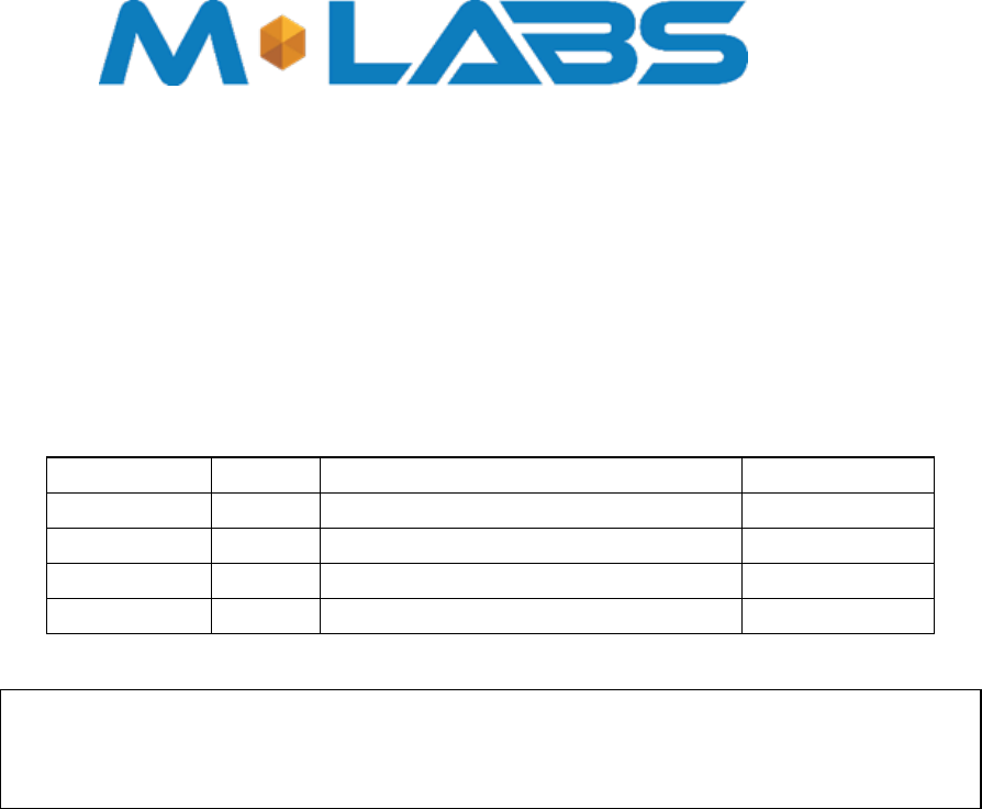
1 Introduction
The LTE is a self-contained vehicle trackin g
device that combines GPS location with LTE
CAT1 cellular connectivity. It is primarily a location reporting device that responds to requests
(user, server) and events (timers, geo-fences). Data reports consist of a single record that
contains all location data and system status.
The device comes pre-configured from the factory. It is ready to use. The LTE appears to
a user or a server application as an endpoint device. It can be queried, updated and configured
either through a serial connection, an over the air IP connection, or through SMS messaging.
The LTE
presents itself over these connections as an enhanced cellular modem with
attached functional elements. These elements include:
GPS location engine
Accelerometer
Input/outputs dedicated for ignition, relay, buzzer, and general purpose
Serial UART port
Timers
Watchdog lockup protection
Power management
Event reporting
Voltage monitoring
Access to these elements and general purpose interfaces is done through an extended AT
command set. Configuration parameters are stored to flash memory and are automatically used
on the next power up event. For more details, please reference the AT Command document.
Diagram

© 2017 M-Labs Technologies LLC 6 / 15
This LTE product is designed based on the Sequans Communications or VZ120Q
(LTE CAT 1, wireless
data/SQN3223) b
aseband module, which includes an ARM CPU, 4M serial
flash, LTE_B2&B4&B12 RF transceiver, and triple-band RF front end circuit.
Antennas for cellular and GPS are internal to the device.
2 Hardware Design
2.1 Basic Hardware
Items Requirement
Based on SQN3223 baseband chipset and
SQN3241 RF 4G Transceiver
Cellular Network Interface Support for LTE B12, B4, B2
Frequency B2(MHZ):TX(1850-1910) RX(1930-1990)
B4(MHZ): TX(1710-1755) RX(2110-2155)
B12(MHZ): TX(698-716) RX(728-746)
Antenna Internal Dual Antennas(Main & Diversity)
[B2&B4&B12]
GPS Antenna Dedicate high performance ceramic antenna
UIM requirement Support:2FF SIM Interrupt Mode
No Support: Hot Plug/Unplug
Battery Monitor Internal analog input
Build in battery manager Yes
Interface Debug UART
Application UART
USB
12V DC Input(1A current), Ground
Relay Drive (12V Output ,500mA current)
Dedicated Output for buzzer control
Ignition Input
GPIO
Dedicate Timers Yes
Watchdog External HW via MCU
Motion Detect Supported(GPS/G-Sensor)
LED 2 LED Supported
1- RED; 1- Green
Battery Build in battery(80MAH Lion)
Working Time 4 hours
Power switch No
Power Cable color 10 colors
Power Cable connector type 10-pin connector
Power Consumption < 5Watts
US130Q LTE E-UTRA
Baseband Module
US130Q LTE E-UTRA
4G

© 2017 M-Labs Technologies LLC 7 / 15
The LTE provides support for specialized hardware features through extended AT
commands. The features supported include the following:
GPS
GPS location functionality is provided by the device GPS receiver. NMEA GPS records can be
extracted in real time from the unit via the UART connection using special debug commands
that are outside the scope of this document.
GPIO
One dedicated input, two dedicated outputs, and one general purpose IO are presented to the
external
environment
on the main connector. They are capable of providing system interrupts to
generate a report or drive logic levels to external devices. These lines are 2.8V logic level and
are 16V tolerant. These pins default to input and are pulled down representing 0 when
disconnected. They should be asserted to a known value if used.
LED’s
Two LED status indicators are provided to verify correct installation and operation. The status
LEDs are color coded and directly convey the status of the cellular and GPS subsystems as
described in the table below. Their valid operation also indicates operational status and power.
LED Function Status
Red GPS On: GPS satellites acquired and Locked
Flash Slow: GPS satellite search is in progress
Off: No power or GPS subsystem fault
Green Cellular
Connection On: Indicates LTE connection is made
Flash Slow: LTE subsystem initialization in progress
Flash Fast: LTE initialization but no data connection available
Off: No power or LTE subsystem fault
The LTE
provides user control allowing the LEDs to be extinguished once installation is
verified. This feature reduces power and further conceals the LTE
Tracker from untrained
parties wishing to defeat its operation.
UART
There are two UART’s provided. A debug UART port is provided for AT commands, data
interaction and optionally for application specific control. A second, application UART is
provided to be used as an expansion port for sensors and other peripherals

© 2017 M-Labs Technologies LLC 8 / 15
USB
The USB port is provided for provisioning or debug.
Relay Driver
A 500mA sink capable output pin is provided. This pin is meant to drive a relay coil indented to
interrupt the starter solenoid relay for the ignition circuit to a car.
Power and Battery
The battery monitor is internal analog input scaled such that the DC value of the power input
pin to the LTE
system is measured. This value is scaled to span the most significant 8 bits
of the A/D and consequently covers a scale from 0 to 25.5 Volts.
Timers
Timers resident on the baseband chip generate periodic interrupts for power down wakeup,
watchdog support, periodic report generation and other timer related functions.
Watchdog
SQN3223 chipset provides internal software Watchdog. The LTE device also includes an
MCU that acts as a failsafe external watchdog. The MCU power cycles the system, if no
activity is detected for 1 hour.
Accelerometer
The accelerometer can be used for motion detection and driver behavior monitoring.
2.2 Basic RF Performance
Items Requirements Remark
TRP free space B2/B4/B12: >= 20 dBm TRP free space
TIS free space Main: <= -91dBm
Div: <= -88dBm
TIS free space
Antenna loss <= -3dB TRP-TX Power Conducted
Antenna Loss <= -3dB RX receive sensitivity conducted
– TIS
Board RF Specification
LTE_B4 RX
B4 Frequency range 2110-2155MHZ
Sensitivity -99.5dBm (10MHZ_50RB_Downlink)
Dynamic range -23~-99.5dBm

© 2017 M-Labs Technologies LLC 9 / 15
LTE_B4 TX
B4 Frequency range 1710MHz~1755MHz
Maximum Frequency error ±10Hz
Maximum output power 23.38dBm
Minimum control output power <-40dBm
ACLR UTRA2: 46.48 UTRA1: 41.21 E-UTRA1:39.23
UTRA2: 43.87 UTRA1: 40.51 E-UTRA2:38.05
OBW 8.87MHZ (10MHZ Nominal)
IQ OFFSET < -55.6dbc

© 2017 M-Labs Technologies LLC 10 / 15
EVM <3%
LTE_B12_RX
Frequency range 728MHz ~ 746MHz
Sensitivity -100dBm (10MHZ_50RB_Downlink)
Dynamic range -23 ~ -100dBm
LTE_B12 _TX
Frequency range 699MHz ~ 716MHz
Maximum Frequency error ±10Hz
Maximum output power 23.29dBm
Minimum control output power <-40dBm
ACLR UTRA2: 45.48 UTRA1: 41.41 E-UTRA1:39.43
UTRA2: 44.87 UTRA1: 41.51 E-UTRA2:38.25
OBW 8.87MHZ (10MHZ Nominal)
IQ OFFSET < -54.7dbc
EVM <3%
LTE_B2 _RX
Frequency range (1930-1990)MHZ
Sensitivity -100dBm (10MHZ_50RB_Downlink)
Dynamic range -23 ~ -100dBm
LTE_B2 _TX
Frequency range ( 1850-1910)MHZ
Maximum Frequency error ±10Hz
Maximum output power 23.28dBm
Minimum control output power <-40dBm
ACLR UTRA2: 46.48 UTRA1: 41.51 E-UTRA1:39.49
UTRA2: 44.45 UTRA1: 42.51 E-UTRA2:38.29
OBW 8.87MHZ (10MHZ Nominal)
IQ OFFSET < -54.9dbc
EVM <3%

© 2017 M-Labs Technologies LLC 11 / 15
GPS
Frequency Support
L1-band (1.57542GHz)
Channels: 210 PRN, 66 Search, 22 Simultaneous
tracking
Sensitivity
Sensitivity (UHIS):
Tracking: -156dBm
Reacquisition: -153dBm
Acquisition: -144dBm
Tracking Time Requirement
Acquisition time:
Hot: <2s
Warm: <15s
Cold: <60s
Reacquisition: 2s - 10s Depends on signal level
2.3 Certification and Safety
Items Requirement
Drop Design 1.2 meter 6 direction standard drop test
Temperature Range -20 to 40°C Operation
-50 to +100° C Storage
Humidity: 20% to 90% Operation
10% to 95% Storage
Altitude: -500 to +18,000m
Vehicle ISO Test ISO7637-2-2004; ISO7637-3-2007; ISO10605-2008;
ISO16750-2-2010
FCC Certification FCC 47 CFR Part 15
Other Certifications Industry Canada (optional)
ESD Requirement 10KV non-Conductive
Operator Certifications Verizon and/or PTCRB / AT&T (optional)

© 2017 M-Labs Technologies LLC
11 / 17
3 Software Features
3.1 Basic Software
Items Requirement
Network Interface LTE B2, B4, B12
IP Stack IPV4/IPV6
Upgrade Method Remote update/ PC tool
Remote Update Supported – including OMA DM
Power Modes Supported
AT Commands Supported
Report Su
pp
orted: 3000 records
Drivers GPIO,LED,GPS,UART, USB Accelerometer
GPIOs Interrupt for Ignition Status, Buzzer, Relay
LEDs GPS Status, Network Status
Watch Dog Supported
Reset Soft reset, hard reset, GPS reset, RF reset
Startup Banner Supported
3.2 Remote Update
The LTE supports OTA field upgrades of the resident application. An over the air
TFTP
(Trivial File Transfer Protocol) connection is made over a
n IP
connection. A replacement file is
then transferred from a server to the LTE and that file replaces the previous application
image. Additionally the whole stack can be updated using an OMA- DM protocol.
3.3 Power Modes
The LTE device supports several power modes that are set by AT commands. In full
power mode the GPS is active and the cellular subsystem will maintain a persistent cellular
connection whenever service is available. IP connection is maintained according to the
configuration of the device.
The device can be put in low power mode whenever it runs on a backup battery or if the external
battery is low or if it is not moving. In low power mode the GPS is not running and the LED’s
are off. The device would return to full power whenever an event occurs that triggers a report.
Those events include:
Periodic report
GPIO change
IP change
Battery threshold
Heartbeat
Watchdog
© 2017 M-Labs Technologies LLC
12 / 17
Power-up
Ignition
Trip start and stop
Any hardware or software reset will return the device to full power mode.
3.4 AT Commands
Extended AT commands are specific to the LTE device. They are closely based on
commands that are as similar as possible industry common devices and are essentially subsets of
standard LTE
commands. Native AT commands supported by the SQN3223 modules are
also available via the serial and USB interfaces.
Command Summary
The following commands are specific to the LTE. The commands listed are intended to
be similar to counterparts found in other tracking products by the same vendor.
1. AT+IONAA: Set append mode
2. AT+IONACK: Set acknowledgement mode
3. AT+IONAPN: Set APN
4. AT+IONBIN: Read the factory core software version (read only)
5. AT+IONBZ: Buzzer setting
6. AT+IONCV: Configuration version
7. AT+IONDI: Set distance interval interrupt
8. AT+IONDTE: Set driving time events
9. AT+IONFR: Restore factory defaults
10. AT+IONGF: Set geo fence borders
11. AT+IONGFH: Set geo fence around current location
12. AT+IONGPIO: GPIO Read/Write
13. AT+IONGS: GPS State report
14. AT+IONHB: Heartbeat
15. AT+IONHC: Heading Change
16. AT+IONINFx: List system information segments
17. AT+IONIP: Set target server IP address and port number
18. AT+IONIPC: IP Change report
19. AT+IONIS: Ignition State
20. AT+IONLT: LEDs’ Timing and Intensity
21. AT+IONLPORT: Set the local IP port number
© 2017 M-Labs Technologies LLC
13 / 17
22. AT+IONNR: Set time before IP session is closed and restarted
23. AT+IONNW: Set watchdog timeout if no network found
24. AT+IONPM: Set auto power down mode
25. AT+IONRF: Report Format – Binary
26. AT+IONRI: Set report timer interval
27. AT+IONRM: Report Mask
28. AT+IONRN: Queue report record for transmission
29. AT+IONRR: Set reset report
30. AT+IONRS: Reset setting - soft/hard, periodic
31. AT+IONSD: Set SMS response destination
32. AT+IONSI: Set interrupt
33. AT+IONSQ: Set queue length
34. AT+IONSR: Set relay driver (GP3) state high or low
35. AT+IONSV: Read the factory application software version (read only)
36. AT+IONTA: Tow Alert
37. AT+IONTID: CDMA tower ID and location data
38. AT+IONUA: Update application firmware OTA
39. AT+IONUC: Update configuration files OTA
40. AT+IONVO: Virtual Odometer
41. AT+IONVTO: Virtual Trip Odometer
3.5 Ack’ed Mode
UDP is not a 100% reliable connection and occasional reports or command/responses may be
lost. Since all commands have responses, the server can repeat any command to which there is no
response. In order to assure reliable reception of reports, LTE devices can be confi gured
either in Normal or Ack’ed mode to send the reports. In the Normal mode the reports are simply
sent “as is” with no acknowledgment from the server. In the Ack’ed mode every report sent is
expected to be acknowledged by the server by sending back an ACK message back. If
acknowledgement
is not received within the specified timeout, the report is re-sent. If the report is
not acknowledged after the specified number of attempts, it is queued. If acknowledgement is
received after the report is queued (i.e. past timeout of the last attempt), it is ignored.
Report is not considered “complete” until its acknowledgement is received. Thus, if report X is
sent and report X+1 is triggered while waiting for acknowledgement of X, report X+1 will be
queued until such acknowledgement is received and only then sent. The LTE will attempt
to re-send queued report(s) every time a new report is triggered. If there is more than one report
© 2017 M-Labs Technologies LLC
14 / 17
queued, the reports will attempt to be sent in the order of triggering and only once the report is
acknowledged, the next report is attempted. This assures that reports are sent and received in
order
Ack’ed mode assures that all reports are received, but adds overhead in time and data. Report
that is not
acknowledged
is sent again and
eventually
will be queued and sent again. The number
and frequency of re-tries is configurable via the Report Acknowledgement command.
3.6 Event Report Format
Reports are encoded as binary hex. It is also echoed to the debug UART in ASCII format.
3.7 Reset
There are a number of resets available on the device. Soft reset only restarts the software
running on the device. Hard reset is caused by resetting the whole basband module via a reset
pin. There is also an option to reset the GPS and the cellular sub-systems individually.
3.7.1 Context Preservation
When a self-initiated reset is performed due to Network Watchdog or by the Reset command
(modes 0, 1), the context of the system is being preserved and is restored after the reset. The
context includes all the periodic timers, the report queue, the odometer, etc. This allows reset
of the unit as a troubleshooting
or preventive
measure without losing reports that are already in
the queue or are pending on running timers. Note that the reset process may cause 1-2min of
inaccuracy in the timers and should not be considered as very precise.
3.8 Startup Banner
After a reset a startup banner is printed through the UART only.

© 2017 M-Labs Technologies LLC
15 / 17
4 Test Method
4.1 Hardware
Test Item Description
Baseband Function Test • Power Input Test
• Power Consumption and Current Test
• Heat Dissipation Test
• UART Stability Test
• GPIO Level Test
• LED Stability Test
• Drop Down Test
• ESD Test
• High/Low Temperature Test
• Humidity Test
RF Test • RF Performance Test
• GPS Performance Test
• Antenna Performance Test
4.2 Software Test
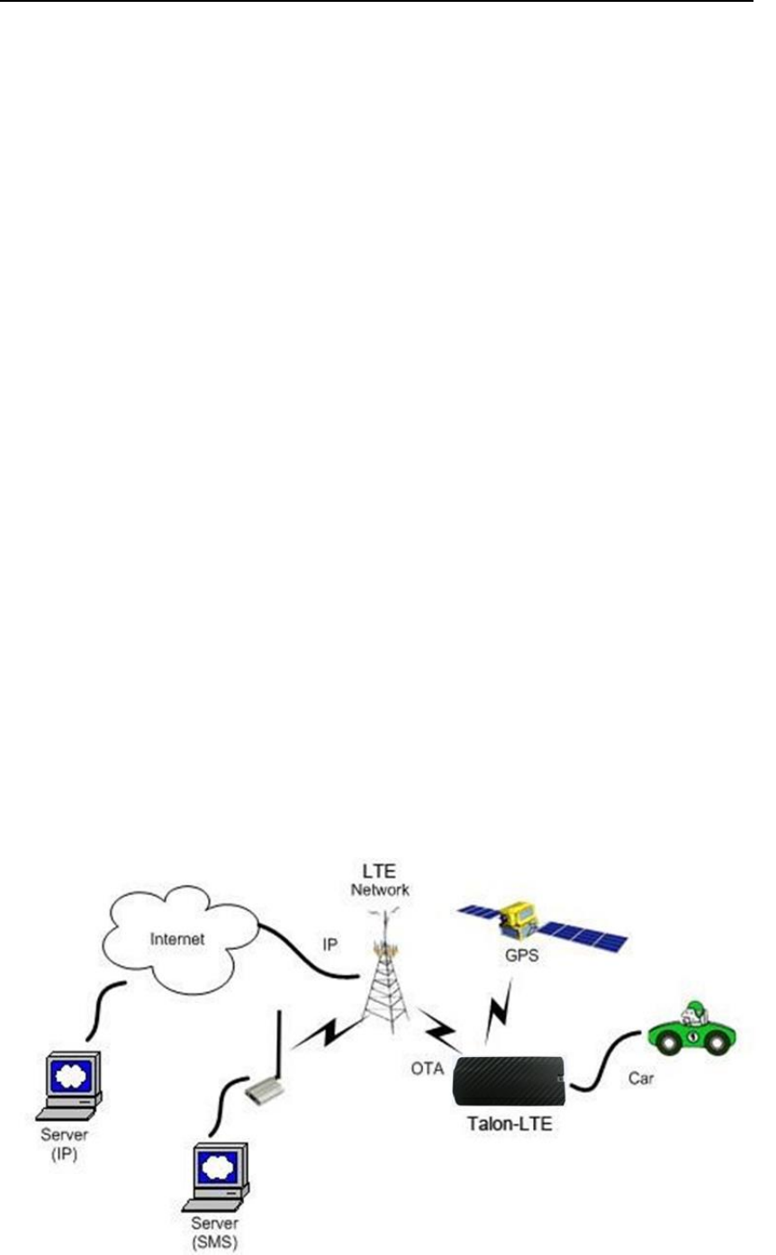
Test Environment Construct
Message Test environment
1. USB dongle and PC as message server
2. Send message to LTE
UDP Test environment
1. Connect dongle to PC and create dialup as ip server
2. LTE create IP connection to server
UART Test environment
1. Connect LTE to PC with com serial cable
2. Open Terminal tool and send at command
3. Response can be shown at terminal window
© 2017 M-Labs Technologies LLC
16 / 17
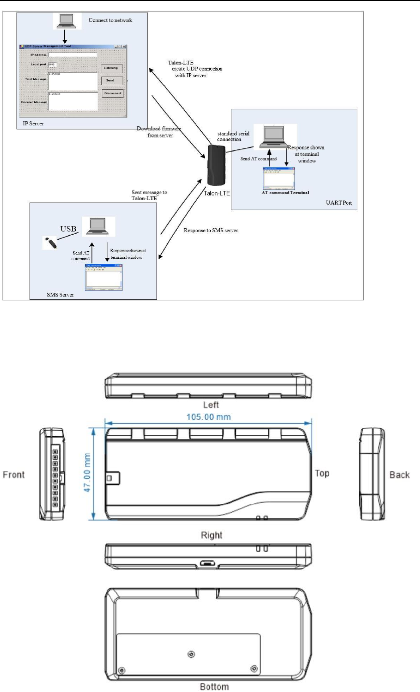
Mechanical Structure (mm)

© 2017 M-Labs Technologies LLC
17 / 17
FCC Statement
This equipment has been tested and found to comply with the limits for a Class B digital device, pursuant
to Part 15 of the FCC Rules. These limits are designed to provide reasonable protection against harmful
interference in a residential installation. This equipment generates uses and can radiate radio frequency
energy and, if not installed and used in accordance with the instructions, may cause harmful interference
to radio communications. However, there is no guarantee that interference will not occur in a particular
installation. If this equipment does cause harmful interference to radio or television reception, which can
be determined by turning the equipment off and on, the user is encouraged to try to correct the
interference by one or more of the following measures:
-- Reorient or relocate the receiving antenna.
-- Increase the separation between the equipment and receiver.
-- Connect the equipment into an outlet on a circuit different from that to which the receiver is connected.
-- Consult the dealer or an experienced radio/TV technician for help.
This device complies with part 15 of the FCC Rules. Operation is subject to the following two conditions:
(1) This device may not cause harmful interference, and (2) this device must accept any interference
received, including interference that may cause undesired operation.
Changes or modifications not expressly approved by the party responsible for compliance could void the
user's authority to operate the equipment.
ISEDC Warning :
This device complies with Innovation, Science, and Economic Development Canadalicence-exempt RSS
standard(s). Operation is subject to the following two conditions:
(1) this device may not cause interference,
(2) this device must accept any interference, including interference that may cause undesired operation
of the device.
Le présent appareil est conforme aux CNR d' Innovation, Sciences et Développement
économique Canada(Industrie Canada) applicables aux appareils radio exempts de
licence. L'exploitation est autorisée aux deux conditions suivantes : (1) l'appareil
nedoit pas produire de brouillage, et (2) l'utilisateur de l'appareil doit accepter tout
brouillage radioélectrique subi, même si le brouillage est susceptible d'en
compromettre le fonctionnement
This equipment complies with FCC radiation exposure limits set forth for an uncontrolled environment .This
equipment should be installed and operated with minimum distance 20cm between the radiator& your body.
This transmitter must not be co-located or operating in conjunction with any other antenna or transmitter
FCC Radiation Exposure Statement:
Cet ÿuipement est conforme aux limites d'exposition de la radiation dÿerminÿs pour un
environnement non contrÿ? Cet ÿuipement devrait ÿre install?et ÿre actionn?avec la distance
minimum 20cm entre le radiator& votre corps.Cet ÿetteur ne doit pas ÿre Co-plac?ou ne fonctionnant
en mÿe temps qu'aucune autre antenne ou ÿetteur.
This equipment complies with FCC radiation exposure limits set forth for an uncontrolled environment .This
equipment should be installed and operated with minimum distance 20cm between the radiator& your body.
This transmitter must not be co-located or operating in conjunction with any other antenna or transmitter