M Labs Technologies PL01 Wireless Communication Device User Manual
M-Labs Technologies, LLC Wireless Communication Device
UserManual.wiki
>
M Labs Technologies
>
PL01 User Manual
User Manual
Navigation menu
Upload a User Manual
Namespaces
Wiki Guide
HTML
PDF
Info
Views
User Manual
Discussion / Help
Navigation

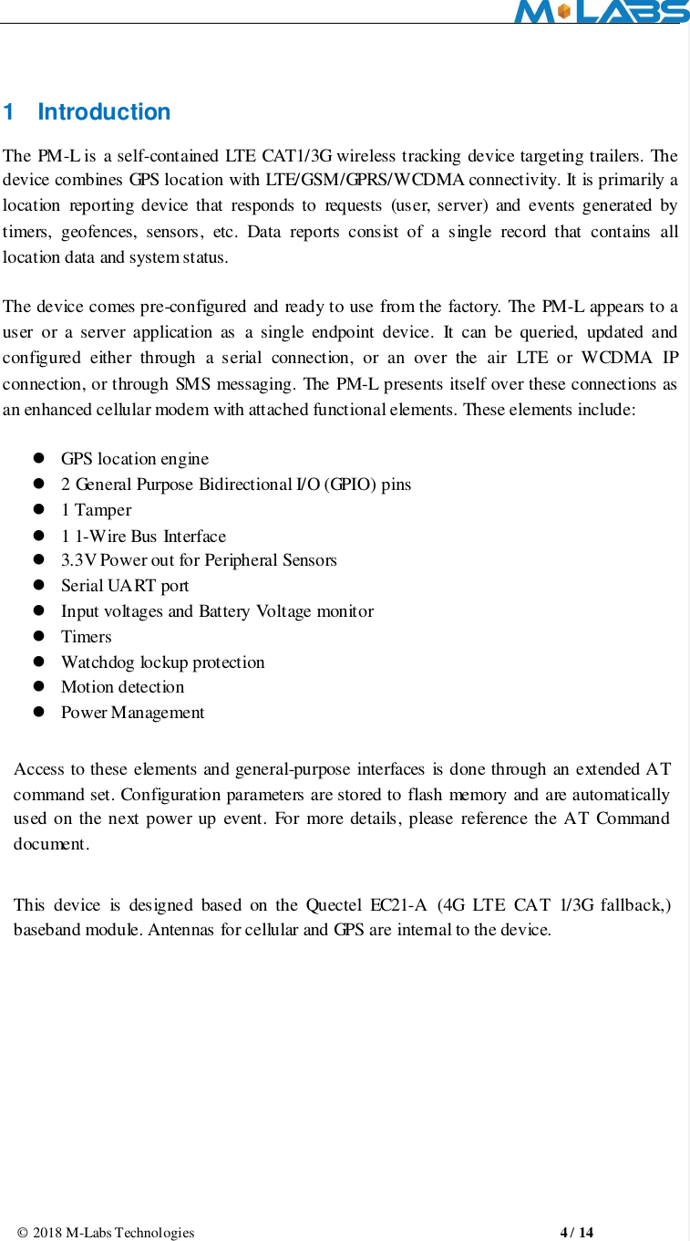
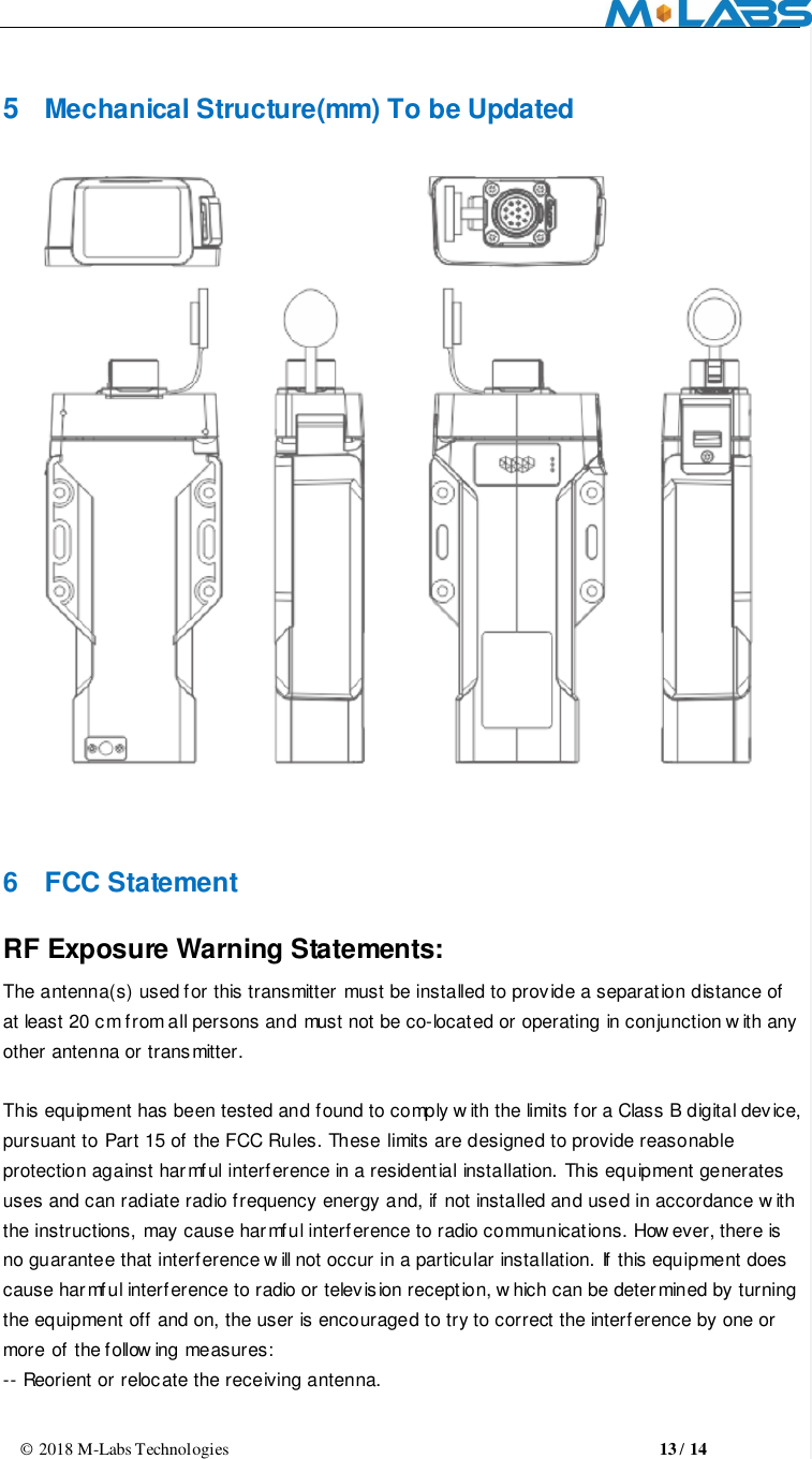
![© 2018 M-Labs Technologies 5 / 14 Figure 1 2 Hardware Design 2.1 Basic Hardware Items Requirement Baseband Module Based on Quectel EC21-A baseband module Air Interface Support for LTE B12, B4, B2 WCDMA B2, B4, B5 Frequency B2(MHZ):TX(1850-1910) RX(1930-1990) B4(MHZ): TX(1710-1755) RX(2110-2155) B12(MHZ): TX(699-716) RX(729-746) B5 (MHZ): TX (824-849) RX (869-894) Antenna Internal single antenna UIM requirement Support: 3FF SIM interrupt mode No Support: Hot plug/unplug GPS Antenna Dedicate high performance ceramic antenna Power Inputs 12V DC Input(1.2A max current) Main/Aux/Solar inputs Interface Voltage/Battery Monitor Build in battery manager Dedicate Timers UART TX/RX GPIO1 and GPIO2 1-Wire Bus Interface 3.3V Power out Internal analog input scaled Watchdog Supported PM-L LTE Network 批注 [GE1]: Update image with LTE Network, PM-L device name, and change car to trailer image.](https://usermanual.wiki/M-Labs-Technologies/PL01/User-Guide-3990648-Page-5.png)
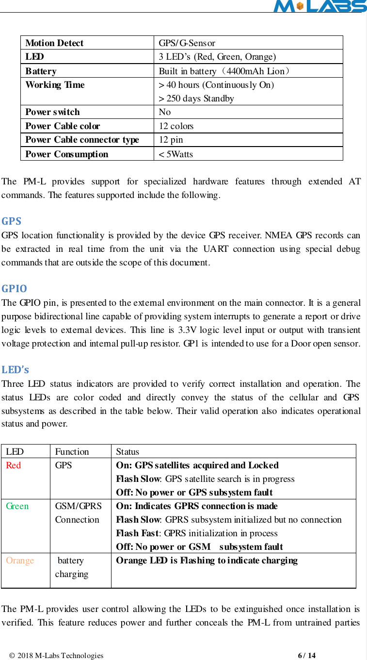
![© 2018 M-Labs Technologies 7 / 14 wishing to defeat its operation. UART A UART is provided for AT command and data interaction and optionally for connection to peripheral sensors Relay Driver A 500mA sink capable output pin is provided. This pin is meant to drive a relay coil indented to operate a door opening device. 1-Wire Bus Interface The 1-Wire bus interface can be connected to sensors that support the 1-wire serial protocol such as Temperature sensors or driver identification. 3.3V Power Out 3.3V Power output is available to power peripheral sensors such a cargo sensor. The power is turned on only when the peripheral sensor is being read to save power. Input Voltage and Battery Voltage Monitor The Input Voltage monitors and battery voltage monitor are internal analog inputs scaled such that the DC value of the voltage input pin to the PM-L system and internal battery voltage is measured. This value is scaled to span the most significant 8 bits of the A/D and consequently covers a scale from 0 to 32V for Input Voltage and 0 to 9V for internal battery voltage Timers Timers resident on the baseband chip generate periodic interrupts for power down wakeup, watchdog support, report generation and other timer related functions. Report timers are supported by related AT command and cause generation of periodic reports. Watchdog The Quectel EC21-A chipset provides internal software Watchdog. Also the PM-L includes an MCU that acts as a failsafe external watchdog. Motion Detect Configurable through AT commands the unit can go to a low power mode when the main power is removed until motion is detected. Upon wakening, a report can then be generated, and the GPS enabled to detect drive events. 2.2 Certification and Safety Items Requirement Drop Design 1.2meter 6 direction standard drop test Temperature Range -20 to 65C Operation -40 to +85° C Storage 批注 [GE2]: To be updated…but do we really need this detail? Can we delete this section?](https://usermanual.wiki/M-Labs-Technologies/PL01/User-Guide-3990648-Page-7.png)
![© 2018 M-Labs Technologies 8 / 14 Humidity: 20% to 90% Operation 10% to 95% Storage Altitude: -500 to +18,000m Vehicle ISO Test ISO 7637-2-2004; ISO 7637-3-2007; ISO 10605-2008; ISO 16750-2-2010 FCC Certification FCC 47 CFR Part 15 ,Part 2, Part 22, Part 24, Part 27 Others Operator Requirement Industry Canada/ PTCRB ESD Requirement 10KV non-Conductive 3 Software Features 3.1 Basic Software Items Requirement Network Interface CAT 1 LTE: B2, B4, B12, WCDMA: B2, B4, B5 IP Stack Ipv4/IPV6 Upgrade Method Remote update / PC tool Remote Update Supported Power Modes Supported AT Command Supported Report Supported;3000 records Driver GPIO,LED,GPS,UART,3.3V out GPIO Interrupt for Door Open Detect LEDs GPS Status, Cellular Status, Power State Watch Dog Supported Reset Soft reset Startup Banner Supported 3.2 Remote Update The PM-L supports OTA field upgrades of the resident application. An over the air TFTP (Trivial File Transfer Protocol) connection is made over an IP connection. A replacement file is then transferred from a server to the PM-L and that file replaces the previous application image. 3.3 Auto Execute The Auto Execute Utility copies the contents of file system.exf into system executable RAM and executes it from there. This file is the factory default application. Another file named custom.exf can be loaded into the file system. Auto Execute will look first for a file named update.exf and load and execute that in place of custom.exf if it exists. If update.exf executes successfully, the previous copy of custom.exf is deleted from the file system and update.exf is renamed to custom.exf. 批注 [GE3]: To be updated.](https://usermanual.wiki/M-Labs-Technologies/PL01/User-Guide-3990648-Page-8.png)