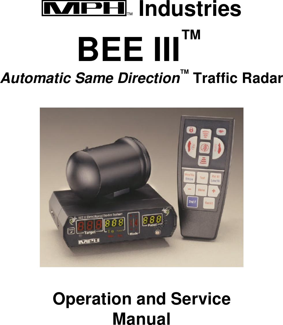
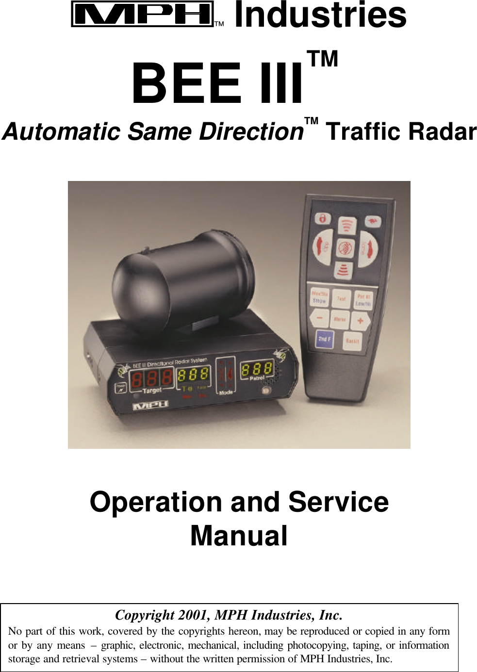
M P H KBEE-003 Vehicle Mounted Police Traffic Radar User Manual b3manual

M P H Industries Inc Vehicle Mounted Police Traffic Radar b3manual

Manual

™ Industries  BEE III™ Automatic Same Direction™ Traffic Radar    Operation and Service Manual
  ™ Industries  BEE III™ Automatic Same Direction™ Traffic Radar    Operation and Service Manual    Copyright 2001, MPH Industries, Inc. No part of this work, covered by the copyrights hereon, may be reproduced or copied in any form or by any means – graphic, electronic, mechanical, including photocopying, taping, or information storage and retrieval systems – without the written permission of MPH Industries, Inc.
Table of Contents  Introduction          2  Getting Started - An Introduction to the BEE III        3  Advanced features of the BEE III        12   Fastest vehicle mode          12   Same direction mode          12   POP™ mode      13   Stopwatch mode          14  A Detailed Explanation of the BEE III’s Features       16  Practical use of the BEE III          16  Display       18  Remote Control      20  Operation       24   Power up self test          24   Tuning fork tests and Tuning Fork mode    24   Harmonic detection          26   Range and radar placement        26   Power source      26   Fuse replacement          26   Remote control batteries        27  General Operational Considerations          28  Understanding traffic radar          28  Operational concerns of fastest and same direction modes  32  Interference information and precautions      35 Legal guide       37  FCC Licensing Requirements      39  BEE III Accessories       40  Quality Control Procedures and Repair of the BEE III    41  Servicing the BEE III       42  Warranty        43  MPH BEE III Specifications      44
 2Operational Recommendations         48
 3Introduction  MPH Industries, Inc. designed the BEE III Doppler radar with the police officer in mind.  The radar is easy to operate and includes the performance and features needed for today's traffic environment.  The BEE III is the most useful and flexible radar available; it is a full-featured moving radar with fastest and same direction capability.    The BEE III utilizes MPH’s patented Automatic Same Direction™ (ASD™) technology.  ASD allows the BEE III to automatically measure the speeds of targets moving in the same direction as the patrol vehicle, thereby eliminating the slower/faster button required by the previous generation of same direction radars.  ASD™ also allows the radar to measure the speed of targets moving in one direction while completely ignoring targets moving in the opposite direction.  In addition, the BEE III utilizes MPH’s exclusive POP™ technology, allowing it to measure speeds while simultaneously remaining invisible to radar detectors.  The BEE III employs state-of-the-art digital signal processing (DSP) technology, which allows the unit to have both high performance and high reliability in a small package.  The digital signal processor is a specialized microprocessor chip, which can perform the required calculations for detecting patrol and target speeds very efficiently.  The MPH BEE III is composed of one or two antennas, a wireless remote control, and a separable display/counting unit.  MPH designed the BEE III using only the highest quality parts.  Combined with the workmanship provided by MPH`s Manufacturing Department, the BEE III will provide years of high performance.   The MPH BEE III offers more than features and performance.  MPH provides training through our network of experienced field representatives.  We know that our success depends upon your success with our equipment.  We are dedicated to keeping our customers satisfied.  The following pages describe the operation of the MPH BEE III radar.  We can also provide useful information on the legal aspects of traffic radar at your request.  We at MPH Industries thank you for purchasing our equipment.  We wish you the greatest success in your speed enforcement program.  We are proud that the BEE III is a part of your department.   BEE III, Automatic Same Direction, ASD, MPH Industries, the MPH logo,  and POP are trademarks of MPH Industries, Inc.
 4Getting Started - An introduction to the BEE III  This step-by-step guide will help you get started using the BEE III and show you how to operate it in all of its different modes.  Working through this tutorial will take less than an hour, and it will teach you everything that is necessary to take full advantage of the BEE III's capabilities.  It will take much less time for you to learn the BEE III's functions with this tutorial than it will if you try to figure them out on your own.  This guide assumes that you are familiar with basic radar operation.  It will also be beneficial if you have experience operating other radar units.  We encourage the customer to copy these pages out and use them as a checklist for training.  Checkboxes are provided to keep track of your progress.  Install the BEE III   Install the BEE III unit in the vehicle in accordance with the instructions supplied with the radar’s mounting brackets.    Care should be exercised to ensure that none of the radar components or cables are placed in the vehicle’s airbag deployment zones.  Otherwise, the radar may become detached during the explosive deployment of the airbag and become a dangerous projectile that could seriously injure the occupants of the vehicle.  If you have any questions regarding the proper installation of the BEE III, please contact MPH.  If you have any questions regarding the airbag deployment zone of your particular vehicle, we suggest that you contact the vehicle’s manufacturer.  Turn the BEE III on  Press and release the Power button on the readout unit.  This will cause the BEE III to power up. When first turned on, the BEE III will start up in the mode in which it was turned off, except that the unit will always power up in standby with the range set to maximum.
 5Perform a self test  Press the Test key, located approximately in the middle of the remote control.  This causes the radar to perform an internal of the processing circuitry.  First, the radar will light up all of its display elements in a segment test.  Next the radar will tell you the software revision, for example “bEE III 010” for BEE III revision 1.0.  Finally, the radar will test itself with two Doppler tones, first in stationary mode at 32 mph and then at 32/32 in moving mode.  You will also hear the Doppler audio associated with these test speeds.  If all of the checks are successful, the radar will respond with a double “test OK” beep.  Otherwise the radar will indicate a “fail” condition by displaying “Err”.  Immediately after passing the internal test, the letter “F” will be momentarily displayed in the target window. The “F” indicates that the radar is in the tuning fork test mode. See page 24 for details on the tuning fork tests.  The BEE III periodically tests itself while the radar is operating.  If no errors are detected, the radar will give indication of this with a “test OK” tone set.  If an error is detected, the BEE III will indicate this by displaying “Err” and ceasing to display target speeds.  In the event of a test failure, the radar should be removed from service until the problem can be remedied.  In no case will the BEE III process speeds when an error condition is present. Select the operating mode  Look at the radar’s remote control.  You will notice a cluster of raised rubber buttons on the top portion of the remote.  Two of these buttons, the half-moon shaped ones, are used for used to select the operating mode.  The left button selects opposite direction moving mode (normal moving radar), and the right position selects same direction moving mode.    Press the Front button.  This causes the front antenna to transmit, if one is connected to the radar.  Notice that the radar responds to all wireless commands with a beep, letting you know the BEE III understood and executed the action.   The selected mode will be illustrated in the MODE window, which is located on the BEE III's front panel.  The green car is lighted (meaning that you are not in Standby), and since you are in opposite direction moving mode on the front antenna, the arrow in the opposite lane of traffic ahead of the patrol car is
 6lighted.  In all cases, the arrows indicate the traffic that is being monitored. Now, press the Standby (Stndby) button on the remote.  Notice that the red X is lighted, indicating that the unit is in standby.  None of the arrows are lighted since no traffic is being monitored.  You’ll also notice that the radar reads either “Ci” or “Hi” in the Patrol window; we’ll address this later.  Now press the Rear button on the remote (if the radar is equipped with a rear antenna).  The arrow that is behind the patrol car in the opposite lane of traffic is lighted, since the radar is in opposite direction moving mode and transmitting on the rear antenna.  Now press the Same key on the remote.  The lighted arrow behind the car moves from the opposite lane of traffic because the same direction traffic behind the patrol vehicle is being monitored.    Press the Front key.  The lighted arrow moves to the front of the green patrol car, since same direction traffic in front of the patrol vehicle is being monitored.    You will notice that there is not a “Slower” or “Faster” key on the BEE III like there is on other same direction radars.  This is because the BEE III has Automatic Same Direction™ technology, a patented technology that allows it to process same direction targets automatically, so you do not have to press a button to tell the radar whether the target vehicle is moving faster or slower that your patrol vehicle is.  Try out Stationary mode  The operator can toggle between moving mode and stationary mode using the Mov/Sta button on the remote control.  This button is located in the upper left side of the flat keypad.  This key can also be used to access the stopwatch mode, which will be discussed later.    Press the Mov/Sta button.  The radar will enter stationary mode.  You can tell this because the “Sta” icon is lighted below the middle window and the Patrol window is filled with dashes.  In moving mode, the “Mov” indicator would be lighted.    In stationary mode, you can select the direction of the targets that you want to monitor.  When you first enter stationary mode, you will notice that both arrows in the display’s Mode window are lighted in the direction of the antenna that you have selected.  This indicates that the radar will measure the speeds of targets moving in both directions, just like a normal radar will.  As soon as a target is measured, the radar will tell you in the mode window the direction that the
 7vehicle is traveling in addition to the speed that it is traveling.  This unique feature helps you to positively identify the vehicle being measured.  Now, press the Same button on the remote.  You will notice that only the arrow corresponding to the patrol car’s lane is illuminated.  This indicates that the radar will only measure the speed of vehicles moving in that direction (moving away from the patrol vehicle on the front antenna and approaching the patrol vehicle on the rear antenna).  The radar will only measure the speeds of vehicles moving in that lane of traffic regardless of whether there is a stronger vehicle moving in the opposite lane of traffic.  The BEE III allows the radar to look past traffic moving in the other lane of traffic to see only the traffic in the lane that interests you.  Now press the Opposite (Opp) button on the remote.  You will notice that the arrow moves over to the other lane of traffic in the Mode window.  In this mode, the radar will only display the speed of vehicles moving in that direction (moving toward from the patrol vehicle on the front antenna and away from the patrol vehicle on the rear antenna).  Like in the previous case, the radar will only measure the speeds of vehicles moving in that lane of traffic regardless of whether there is a stronger vehicle moving in the opposite lane of traffic.    You can toggle between the lane you want to measure by pressing the Same and Opp keys.  If you want to go back to monitoring both lanes of traffic, you must press the Mov/Sta key twice.
 8Perform a tuning fork test  Place the BEE III into stationary mode by pressing the Mov/Sta button on the remote.  Turn the transmitter on to the front antenna by pressing the raised Front button.  Place a ringing fork in front of the antenna.  The radar will read the speed marked on the tuning fork, within one mile per hour, in its red Target speed display.  You may have to move the tuning fork gently toward and away from the antenna in order to get the radar to read it properly.  This is because a tuning fork vibrates both toward and away from the radar, and the radar is expecting to see a target moving either toward it or away from it, but not both directions at once.  Alternately, you may place the radar into Tuning fork mode to perform the test, as is detailed on page 24 of this manual.  Notice again that the radar gives two indications that it is operating in stationary mode.  Firstly, the Sta icon under the middle speed window is lighted.  Secondly, the Patrol window is filled with dashes, indicating that the radar will not pick up a patrol speed.  When you are in moving mode, the Mov icon under the middle speed window is lighted, and there are no dashes in the Patrol window.  Try locking in a speed.  This is a good time to try the lock function.  Place a ringing fork in front of the antenna again.  While the readout is displaying a speed in the Target window, press the remote’s Lock button.  Note that the tuning fork’s speed is locked in the middle window.  Also, the T-lock icon, which is located directly under the BEE III's middle window is lighted, designating that the speed in the middle window is a locked target speed.  Every time that the lock button is pressed, the radar will transfer the speed in the Target window over to the middle window.  Also, if you place the radar into Standby, the operating mode at the time the speed was locked will be displayed in the Mode window.  To clear a locked speed, press either the Front or Rear antenna button.  This will clear the locked speed regardless of whether or not there is a target speed displayed in the Target window.  Locked speeds are also erased in other ways.  If the radar is placed into Standby, the locked speed is preserved, but if the BEE III is then made to transmit again, the locked speed is cleared.  (This is an IACP requirement.)  Also, locked speeds are automatically cleared 15 minutes after they are locked to preserve the
 9integrity of the evidence.  The automatic clearing is preceded by a 30 second countdown if the BEE is in Standby to inform the officer of the imminent clearing of the display so the officer can record the speed before it is erased.   A double click of the lock button will also clear the lock window.  Perform moving mode tuning fork tests  Place the BEE III into moving mode by pressing the Mov/Sta button on the remote.  If the radar is not in opposite direction moving mode, press the Opposite button.  Turn the transmitter on to the front antenna by pressing the raised Front button.  Strike the lower frequency fork on a hard nonmetallic surface and hold the ringing fork in a fixed position two or three inches in front of the antenna with the narrow edge of the fork facing the antenna.  The speed will be shown in the patrol window.  You may have to move the tuning fork gently toward and away from the antenna in order to get the radar to read it properly.  This is because a tuning fork vibrates both toward and away from the radar, and the radar is expecting to see a target moving either toward it or away from it, but not both directions at once.  While continuing to hold the ringing fork in place, strike the other fork and hold it next to the patrol speed fork.  Both forks must be vibrating while being held an equal distance from the antenna.  The radar should display the difference between the forks as the target speed.  For example, for forks marked 35 mph and 65 mph, the patrol would read 35 (low speed fork) and the target would read 30 (high-speed fork minus low speed fork).
 10Try the menu system  Press and release the Menu button on the remote control.  The middle speed window of the readout will indicate “S n”.  This indicates that the squelch is on and Doppler audio is only present when a target speed is being displayed.    Now, do not push any buttons for 5 seconds.  You will notice that the “S n” in the middle window disappears.  In all cases, after the menu buttons have not been pressed for 10 seconds, the BEE III will revert back to its normal operating mode.   Press the Menu key again.  While the “S n” is being displayed, press the “—” key on the remote.  The middle speed will now read “S f”, indicating that the squelch is now turned off and that the Doppler audio will be amplified at all times, even when no target is present.  As you have noticed, the “—” key also acts as an “off” key for the menu.  You can turn the squelch on by pressing the “+” key while the “S” is present in the middle window or turn it off by pressing the “—” key.  Now try pressing the “+” button without pressing the Menu button first.  The middle speed window of the readout will indicate “A 5”.  This is the volume adjustment, and the current volume setting is now one notch higher than it previously was.  Now wait for the text in the middle window to clear itself again.  Press the “—” button.  The middle speed window of the readout will read “A 4”.  The number will be reduced by one from the value that was previously displayed, indicating that the current volume setting is now one notch lower than it previously was.  Pressing the “+” and “—“ buttons without pressing the Menu button first is the easiest way to adjust the audio volume.  You can also adjust the volume by pressing the menu key until “A _” is displayed, where the “_” will be the current volume setting.  You can adjust the volume with the “+” and “—” buttons.  Wait until the middle window clears again and then press the Menu key twice.  The middle window will display “R __”, where the “_” is the current range setting.  Pressing the “—“ button will decrease the range setting by one each time the button is pressed.  To increase the range setting, press the “+” button.    If you press the menu key three times, you’ll notice that the radar will display a “P” in the middle window.  This initiates the POP™ mode, which will be discussed in the section on advanced features of the BEE III.  Place the radar back in standby.  You’ll notice the word “Ci” or “Hi in the Patrol
 11window.  This is an indication on whether the radar is in City mode or Highway mode.  City mode should be used for patrol speeds of 45 mph or less, and it causes the radar to resist false speeds due to combining.  Highway mode should be used for patrol speeds over 40 mph, and it causes the radar to resist shadowing.    Take a look at the remote control.  One of the keys is marked “Pat Bl” in red and “Low/Hi” in blue.  When the key is pressed by itself, it performs the patrol blanking function, which will be described later.  When you press the blue “2nd F” key and then this key, it allows you to toggle the radar between city and highway modes using the “+” and “—” keys. Try it now.  Press the 2nd F key.  You will notice that the radar reads “2nd” in its middle window.  Now press the Low/Hi button.  The middle window will display “P L” or “P H”.  The “L” will be present if you are in city mode and the “H” will be present if you are in highway mode.  Pressing the “+” places the radar in highway mode, and pressing the “—” key places the radar in city mode.  Fastest button  The button with the rabbit icon on the remote control activates the fastest target mode while the BEE III is transmitting.  Fastest mode works in stationary and opposite direction moving mode, but not in same direction moving mode.  The use of this feature will be described later.  When the radar is in tuning fork mode, the Fastest button in used in same direction mode to cause the radar to add the speed of the target speed fork to the speed of the patrol speed fork, simulating a target that is moving faster than the patrol vehicle.  This will also be explained later.
 12Find some real targets (stationary)  Place the BEE III into the stationary mode.  With a target present, press the Front button.  The BEE III will beep and turn the front antenna on, and if the target is strong enough a speed will be displayed in the TARGET window.    If you want to lock in the speed, press the Lock button.  The target speed will move to the middle display window, and the “T lock” icon below that window will light.  After locking a target, the BEE III will continue to track it until the radar is placed into Standby.  The target may be re-locked at any time by pressing the Lock button again.    Now place the radar into Standby.  Notice that the locked speed is preserved in the middle window.  It will be erased if the radar is placed back into transmit mode.  It will also be automatically erased 15 minutes after it is locked in if the radar is not placed back into transmit mode.  Find some real targets (opposite direction moving mode)  Operating in the opposite direction moving mode shouldn't hold any surprises.  The BEE III works like other moving radars.  It can be used in an instant-on mode by waiting to turn the transmitter on until a speeding target is close enough to lock in, or it can be operated in continuous transmit mode.   Note that locking a target speed does not lock the patrol window until the unit is placed into standby.  Keeping the patrol window active allows the officer to continue to verify patrol speed and monitor targets, re-locking at any time.    The patrol blanking function is activated by pressing the “Pat Bl” key on the remote control.  It works when the unit is in standby with a locked target.  Pressing the Pat Bl button alternately blanks and unblanks the locked patrol speed in the Patrol window.  Shut the unit off  The BEE III is turned off by pressing the Power button on the display unit.  There is no need to unplug the unit, it draws very little power.  There is no power down action required on the remote.
 13Advanced features of the BEE III  These modes are useful tools, but many officers have not been exposed to them so they require more explanation.  Please don’t tackle these until you have a few hours of practice using the BEE III in the conventional modes.  A detailed explanation of these more information on modes is contained in the Operational concerns of the fastest and same direction mode section.  Fastest mode  When the BEE III is in any transmitting mode, fastest mode is available by pressing the fastest key, which is located in the upper right hand corner of the remote control.  This will cause the middle display window to be labeled as FAST.  The unit will remain in fastest mode until the fastest button is pressed again or until a target speed is locked in.  The middle speed window will display the speed of the fastest target, while the normal target window continues to display the strongest target.  If the strongest target is the fastest target within the range of the BEE III, the fastest window will be filled with underscores.  The Doppler audio and the mode window will continue to track the strongest target when the radar is in fastest mode.  Locking a target while the BEE III is in fastest mode will lock the strongest target. The BEE III will not allow the locking of the speed that is displayed in the fastest window.  In stationary mode, the radar only looks for faster targets in the selected direction, either Same or Opposite.  If the radar is being operated in both-direction stationary mode, the radar only looks for faster targets moving the same direction as the strongest target is moving.  It therefore may not show the speed of the absolute fastest target in this case.  If you observe a faster target that you want to observe, it is recommended that you place the radar in directional stationary mode and select the direction in which the particular vehicle is moving.  Same direction mode  The BEE III is unlike other same direction radars.  It has Automatic Same Direction™ (ASD™), which allows it to sense the direction a target is moving.  Older, less versatile same direction radars cannot detect the direction that the target vehicle is moving, so they require the officer to press a button to tell the radar if the target vehicle is moving faster or slower than the patrol vehicle.    The BEE III incorporates an advanced, patented technology called Automatic Same Direction™ (ASD™) processing.  This allows the BEE III to know the absolute speed of a same direction target without needing any input from the officer.  In other words, same direction operation is AUTOMATIC.  This makes same direction operation simple, and will remove any questions in court about the officer making the right decision on whether the target vehicle was moving faster or slower than the patrol vehicle.  First, vehicles traveling the same or very near the same speed as patrol are not sensed by the BEE III as targets.  Since the speed differential is small, so is the Doppler shift.  The radar
 14could not easily separate such targets from the reflections of stationary objects like the windshield or hood ornament.  Please keep this fact in mind, because the vehicle nearest you may not be the target displayed by the BEE III if it's speed is within 3 mph of your patrol speed.  The range of the BEE III is greatly reduced in same direction mode.  This makes target identification easier by reducing the number of potential targets.  POP™ mode  This MPH exclusive feature utilizes the latest technology to stop speeders from buying their way around the law with a radar detector.  Using the POP mode, an officer can do quick, accurate speed checks on traffic without alerting approaching vehicles.  When a speeding vehicle is detected, the radar can operate in the conventional mode allowing the officer to check audio, tracking history and lock the target.    With a conventional radar, placing the radar into transmit activates the transmitter.  This allows the user to control the length of time the transmitter is on.  The shortest practical time the user can fire and read a speed is about ½ second.  Most radar detectors easily recognize this, not just alerting the target vehicle but every detector within a mile.    POP mode is turned on by pressing the Menu button three times, until a “P” appears in the middle window.  The operator must then press the “+” key to turn the mode on.  The middle speed window will display “POP”.    If POP mode is turned on, then a momentary press of the Front or Rear antenna button will only turn the transmitter on for the time the radar needs to acquire a target.  This is much shorter than humanly possible.  Radar detectors do not recognize this.  If the detected speed warrants more investigation, the user simply presses the corresponding antenna button down again while the POP speed is displayed and the radar will commence normal operation.  “POP” will disappear from the middle speed window, and you can then monitor the target, develop a tracking history, and lock in the vehicle’s speed.  If the antenna button is not pressed again, the transmission is limited to the single short pulse and does not alert speeders down the road.    In order to lock in a speed, you must allow the radar to enter continuous transmit mode.  Since Doppler audio is not present during the POP pulse and not tracking history is produced, the speed from the POP pulse cannot be locked in.  This is done to prevent any legal concerns regarding speeds locked in on the BEE III radar.  POP mode can be turned off in many ways.  If you place the radar into continuous transmit mode as described above, the radar will exit POP mode.  You can also get out of POP mode by hitting the Menu, Standby, Opposite, or Same buttons on the remote.  When you exit Pop mode, “POP” disappears from the Lock window.
 15Effective use of POP mode  Radar detectors are most effective against stationary radar on long stretches of road with light traffic.  In this situation, each time the speed is measured on a car passing the radar, all cars with detectors within a mile or more are alerted.  This is a perfect application for POP mode.  POP mode is most effective at short range (up to ¼ mile) and where there is some separation between targets.    Degree of effectiveness  When using POP mode, most radar detectors (95%) will not detect anything, even at point blank range.  Some (5%) will detect it when pulses are repeated quickly (less than a few seconds between pulses).  A few (less than a few percent) will give a minor alert, similar to what door openers and other sources cause.  POP mode is invisible in most cases, but always substantially less detectable than conventional radar.    It is recommended to try it on several models of detectors to get a feel for its effectiveness.  A note of caution  Information derived during the POP burst is non-evidential and to be used as advisory information only, in much that same manner as fastest mode is.  Citations should not be issued based solely on information derived from the POP burst since there is no tracking history developed.  If the speed is a violation, the radar must be allowed to enter the continuous transmit mode (by pressing the corresponding antenna button again while the POP speed is still being displayed) so that the tracking history may be developed.  There is no case law allowing traffic radar citations to be issued without a tracking history, and MPH will not assist in the prosecution of citations issued without a proper tracking history.  Stopwatch mode  Stopwatch mode makes use of the precision counters in the BEE III unit in order to measure vehicle speeds without any microwave transmissions.  The function allows an operator to measure the amount of time it takes a vehicle to travel a known distance and then performs a speed measurement using the formula:  Speed = (distance traveled) ÷ (time required to travel that distance)  To enter stopwatch mode, you must press the blue “2nd F” key on the remote control followed by the “Stopw” button.  You should see “.0” in the Target window and a number in the Patrol window.  The Target window is the time window and the Patrol window shows the distance that the measurement will be performed over in yards.
 16The first thing you will need to do is to locate an area over which you wish to monitor speeds.  This area will need two distinct landmarks so that you observe when the vehicle has passed each landmark so that you can accurately start and stop the timer.  You will need to know with good precision how far apart the two landmarks are.    In order to get the best accuracy in stopwatch mode, the measurement time for a vehicle to traverse the distance you select should be at least 10 seconds.  Therefore, you will want the landmarks to be at least 100 yards apart for city use and several hundred yards apart in the country.   Next, you need to tell the radar how far apart the landmarks are.  The first time you operate the stopwatch mode, the distance will be preset to 100 yards.  Each press of the “+” key will increase the distance by 1 yard and each press of the “—” key will decrease the distance by 1 yard.  Also, each press of the Same key increases the distance by 10 yards and each press of the Opposite key decreases the distance by 10 yards.  Finally, each press of the Front key increases the distance by 100 yards, while each press of the Rear key decreases the distance by 100 yards.  The timer is started and stopped by pressing the Lock button.  To measure a vehicle’s speed, you must press the Lock button when the vehicle is passing the first landmark.  When the vehicle has reached the second landmark, you should press the Lock button again.  The timer in the Target window will freeze, and the calculated speed of the vehicle will be displayed in the middle window.  Since this is a locked target speed, the T-lock indicator will be lighted under the middle speed window.  To measure the next vehicle, just press the Lock button.  The speed from the previous vehicle will be cleared, and the time will start at zero.  To exit the stopwatch mode, press the Menu or Mov/Sta key.
 17A Detailed Explanation of the BEE III's Features  Practical use of the BEE III  The BEE III allows the operator to choose various types of use and operation.  The radar may be used as a conventional MOVING, STATIONARY, or PACING radar.  The BEE III also features the SAME DIRECTION MOVING and FASTEST features.  Each of these uses is described below.  Stationary radar  As a stationary radar, the MPH BEE III allows the officer to monitor traffic coming or going while the patrol vehicle is stopped.  This type of operation is usually carried out in known locations of high-speed traffic or complaint areas.  In the stationary mode, the patrol window is not used.    ASD™ technology allows the operator to select a lane of traffic to monitor in stationary mode:  in the same lane as the patrol vehicle, in the opposite lane, or in both lanes.  This selection can be made on either the front or rear antenna.  Also, the operator can choose to monitor that fastest target traveling in the selected direction in addition to the strongest target.  Moving radar (opposite direction)  As a moving radar, the MPH BEE III allows the officer to monitor traffic speeds while carrying on other routine patrol activities.  The unit monitors the speed of each approaching vehicle, displaying that vehicle's speed in the target window.    The patrol vehicle speed is continuously displayed so that the operator may check the speed displayed against the speedometer reading.  If these two speeds correspond, then the officer is assured that the reading of the violator's speed is correct at the instant of determination.  In opposite direction mode, care should be taken by the operator to recognize that the violator is traveling at a higher rate of speed than the norm; that the vehicle is out front, by itself, and nearest the radar; that proper identification of the violating vehicle is made; and at the time of speed determination the patrol vehicle's speed indication on the radar is the same as the reading on the speedometer.  If these steps are taken, and the radar was properly checked for calibration beforehand, the officer knows the radar was operating properly and that the radar made a true and accurate determination of the vehicle's speed.  Fastest Mode  Historically, traffic radar has displayed the strongest target.  Case law has centered on the ability of the radar operator to confidently identify what vehicle is associated with that indication.  It was relatively simple for analog radars to process this method.  Modern DSP radar such as the BEE III can process many targets at the same time, but there is no practical way to display multiple targets and associate them with the correct vehicles.  Fastest mode gives the operator an opportunity to view one other target besides the strongest.  In this
 18mode, the BEE III considers all possible targets (there may be several in range of the radar) and displays the fastest one.    While the speeds indicated in the fastest mode are as accurate as normal targets, visual identification of the offending vehicle is more difficult.  For this reason, the BEE III only displays fastest targets on request when the mode is enabled and does not allow them to be locked.  It is intended to be used as a way to gather additional information about a specific situation.   Fastest mode works in stationary and opposite direction moving modes, but not in same direction mode.  Same direction moving radar  Same direction mode allows the BEE III to track targets moving faster or slower and in the same direction as the patrol vehicle.  This mode is best used in light traffic where visual target identification is easier.  With this feature active, the target speed range is limited to patrol speed ±70%.  The target must be moving at a speed at least 3 mph faster or slower than patrol.  Unlike older radars, the user does not have to press a SLOWER or FASTER button.  ASD™ technology allows the BEE III to detect whether the target vehicle is moving faster or slower than the patrol vehicle and automatically compute the correct target speed.  Pacing radar  The BEE III radar allows the officer an accurate means of pacing vehicles.  In this mode, the BEE III essentially functions as a calibrated speedometer.  The radar should be placed in the stationary mode for this type of operation.
 19Display  The BEE III uses a high contrast LED display with automatic dimming.     Mode  The mode section shows what the radar is doing.  The display is set up like a roadway.  A large red “X” icon in the left lane tells at a glance that the transmitter is in standby.  A large green car in the right line indicates that the transmitter is on.    The operating mode of the BEE III is illustrated with the scene of a patrol car and selected targets.  In opposite direction moving mode, the scene shows an arrow in the left lane of traffic; it is ahead of the patrol car if the front antenna is selected and behind the patrol car if the rear antenna is selected.  In same direction moving mode, the arrows target vehicle is shown moving the same direction as the patrol car.  In addition, moving mode is indicated by “Mov” appearing under the middle speed display window.  In stationary mode, the Mode window works similarly.  Indicators appear in front of or behind the patrol vehicle icon to indicate the selected antenna.  If the opposite lane of traffic is selected, only the arrow in the left lane lights.  If the same lane of traffic is selected, the arrow in the right lane lights.  If both directions of traffic are selected, arrows in both lanes light.  Stationary mode is indicated by “Sta” appearing below the middle speed display window.  Speed windows  The BEE III has three windows for speed display.  These are arranged by function and use color for quick identification at night.    The leftmost display is a dedicated red target window.  This window always displays the strongest target’s speed, even in fastest mode.  Radio frequency error conditions (rFi) are displayed in this window.
 20The middle speed window is yellow and performs two functions; an icon located directly below the window indicates each function.  If the window is being used to display a locked target speed, a T-lock icon is lit.  Only the speed of the strongest target can be locked.  If the middle window is being used to display the speed of the fastest vehicle (fastest mode), a FAST icon is lighted.  General error conditions (Err) are also indicated in this window. The green window on the right side of the display shows the patrol vehicle’s speed in moving mode and is unused (filled with dashes) in stationary mode.  The speed displayed in this window should always correspond with the vehicle’s speedometer.  If a low voltage condition occurs, it will be indicated in this window by “Lo” appearing in the window.  Doppler audio  The BEE III features a speaker on the front panel for Doppler audio.  The BEE III's audio is derived directly from the received Doppler signal (not synthesized) and is useful as an aid in target identification.  The loudness is proportional to the strength of the received signal and increases as the target vehicle approaches.  The pitch of the audio signal increases with higher closing speeds.  The Doppler audio always corresponds to the strongest target, even when the radar is in fastest mode.  Display dimming and infrared remote sensor  A photocell is located on the display panel to automatically adjust the brightness of the display to the ambient light conditions.  An infrared sensor is also located on the display panel to receive commands from the remote control.  Power button  This button controls the power for the BEE III radar.  When the BEE III is turned off, the radar remembers it’s user settings (volume level, mode, etc.), but it does not remember speeds and it starts up in standby mode.  When the unit is next turned on, it powers up using the same settings, saving the user the trouble of resetting the radar to his or her desired
 21Remote Control  The remote is a battery-powered infrared remote control, much like one for a television.  There is no action required to turn power on or off on the remote, but try to avoid storing the remote with any switch depressed in order to avoid draining its batteries.  The BEE III has two main sections of controls located on its face.  These sections are separated by a heavy white line on the label.    Operating mode keys  The most commonly used keys, those used while driving, are at the top of the remote.  They are raised rubber keys and are contoured so that the operator’s thumb is cradled in the center of a five-key cluster, allowing easy control of the radar’s operating mode while allowing the operator to keep his eyes on the road.  All of these keys are backlighted for use at night.  Front:  Places the radar into front antenna mode.  Rear:  Places the radar into radar antenna mode.  Standby:  Places the radar into Standby.  Opposite:  Places the radar into opposite direction mode when moving mode is selected.  Same:  Places the radar into same direction mode when moving mode is selected.  Lock:  Causes the radar to lock the Target speed in the Lock window.    A target locked for 15 minutes will automatically be cleared.  If the unit is in standby, a countdown will be shown in the target window, allowing the officer time to note the speeds before they are erased.  Fastest:  Toggles the radar between fastest vehicle mode and strongest vehicle mode.  Also used in tuning fork mode to simulate a target that is moving faster than the patrol vehicle in same direction moving mode.
 22 Less-frequently used keys.  These keys are flat membrane-type keys that are embossed around their edges to make them easy to identify by feel.    Some of the keys have two colors of text identifying them.  The red text is the default function of the key; pressing the key by itself will cause it to perform this function.  The function in blue text is initiated by first pressing the blue “2ndF” key.  Mov/Sta – Toggles the radar between moving and stationary operating modes.  Stopw – This is accessed using the 2nd F key.  Toggles the radar between normal radar mode and stopwatch modes.  Test  – Manually initiates a self-test of the radar.  The radar will momentarily light all of its displays and icons.  Then it will test itself at various speeds.  If no problems are found, the radar will return to its previous mode of operation.  If a problem is found, the radar will display “Err” in the target window and cease to measure speeds.    The radar performs additional self-tests invisibly during normal operation (initiated automatically).  The radar emits a double beep if no problems are detected and displays “Err” if a problem is found.  Pat Bl – When the radar is in Standby mode, pressing this button will cause the radar to blank the patrol speed display.  Pressing the button while the patrol speed display is blanked will cause the locked patrol speed to reappear.  Low/Hi – This is accessed using the 2nd F key.  Selects the city or highway filter to reduce patrol speed shadowing or combining.  “—” – Works with the menu button.  Causes the radar decrease the audio volume if no selection has been made.  Decreases the setting of the menu item if a menu selection has been made.  Menu  – Allows the selection of modes and setting that do not have individual buttons on the remote.  Is described further in the Menu section of this manual.  “+”– Works with the menu button.  Causes the radar to increase the volume if no selection has been made.  Increases the setting of the menu item if a menu selection has been made.  2nd F  – Causes the radar to select the blue second function of a key instead of the red primary function of the key.  “2nd” appears in the middle window when it is pressed.  Pressing this key a second time causes “2nd” to disappear and allows the radar to select the primary (red) function of a key.
 23Backlt – Manually causes the backlight of the remote control to turn on for 7 seconds.  Once activated, the backlight turns on for 7 seconds after any button is pressed.
 24Menu  No presses of the menu button – Adjust the audio volume  Audio volume has 7 settings (0 through 6, with 0 being “mute”).  During volume adjustment, “A” is displayed in the middle window of the radar, followed by the current setting.  On its initial power-up, the volume is initially set to level 4.  On subsequent power-ups, the BEE III retains the volume setting it had when the radar was turned off.  Pressing the “—” key lowers the volume one level; pressing the “+” raises the volume.  Pressing the Menu key after making and adjustment returns the radar to its normal operating mode.  Pressing the Menu key without making an adjustment causes the radar to move on to the next menu setting.  One press of the menu button – Adjust the squelch  The squelch has two settings:  on and off.  Squelch on causes the radar to only produce an audio tone when a target is present, while Squelch off causes the Doppler return signal to be amplified at all times.  During squelch adjustment, “S” is displayed in the middle window of the radar, followed by the current setting (“n” for on and “f” for off).    On its initial power-up, the squelch is initially on.  On subsequent power-ups, the BEE III retains the squelch setting it had when the radar was turned off.  Pressing either the “—” key or the “+” increases causes the radar to toggle between Squelch on and Squelch off.  Pressing the Menu key after making and adjustment returns the radar to its normal operating mode.  Pressing the Menu key without making an adjustment causes the radar to move on to the next menu setting.  Two presses of the menu button – Adjust the range  The range has 7 settings (1 through 7).  The range setting does not affect the transmitted power, only the sensitivity of the radar.  During range adjustment, “r” is displayed in the middle window of the radar, followed by the current setting.    Upon initial power-up, the range is initially set to maximum.    Pressing the “—” key decreases the range one level; pressing the “+” increases the range.  Pressing the Menu key after making and adjustment returns the radar to its normal operating mode.  Pressing the Menu key without making an adjustment causes the radar to move on to the next menu setting.
 25Three presses of the menu button – Enter POP mode  When the menu button is pressed for the third time, a “P” will appear in the middle window.  Pressing the “+” button places the radar in the POP mode, and “POP” will remain in the middle window of the radar for as long as the POP mode is active.  For a further explanation of this mode, see the section on POP mode on pages 13-14 of this manual
 26Operation  Power up  When the BEE III is first turned on, it will go through a complete self test.  The radar will first perform a light test, in which all of the display's indicators will light, and then the radar will perform a 32 mph internal circuitry test.  BEE III tuning fork tests in general  A tuning fork test is the standard test for proving that the antenna and counting unit are functioning properly.  In older analog radars, the dual tuning fork tests actually checked two different circuits, one each for patrol and target speeds.  However, the BEE III uses a single circuit, the digital signal processor (DSP), to determine both speeds, so that testing the BEE III with a single tuning fork in stationary mode actually ensures that the entire radar is working.  Despite this fact, MPH recommends that you follow your court-proven department guidelines for performing tuning fork checks.  Since the BEE III is a directional radar and the tines of a tuning fork vibrate in both directions, tuning fork tests are more complicated than they are with non-directional radars.  Therefore, the BEE III has a Tuning Fork Mode, which is used while testing the radar with tuning forks.  In this mode, the BEE III works as a non-directional radar, allowing the tuning forks to work properly.  Placing the BEE III in Tuning Fork Mode  When a self test is performed on the BEE III by pressing the Test button on the remote control, the radar does a segment check and a 32 mph test.  After this, the radar displays an “F” in the hundreds digit of the Target window.  This indicates that the radar is in Tuning Fork mode.  The radar will stay in Tuning Fork mode for 30 seconds after the self test is complete.   To place the radar in Tuning fork mode for an extended period of time, press the 2nd F button on the remote control and then the Test button.  The radar will remain in Tuning Fork mode until it is manually taken out of Tuning Fork mode by pressing 2nd F followed by the Test button.  You may need to do this to fully test the radar.  Stationary mode tuning fork tests  To perform a stationary mode tuning fork test, place the radar in Tuning Fork mode and strike the tuning fork on wood or plastic and hold the ringing fork in a fixed position two or three inches in front of the antenna with the narrow edge of the fork facing the antenna front.  This will cause the target speed window to display the speed labeled on the fork (+ 1 mph).  While performing the tuning fork test, the audio volume level may be set to a desirable level.
 27Fastest mode may be tested by using the lower speed tuning fork as above and by placing the ringing higher speed fork into the antenna beam at a greater distance since the fastest target should be a weaker signal than the target.  The Fastest button must be pressed and held on the remote.  The audio will switch to the fastest target when present.  For example, for forks marked 35 mph and 65 mph, the target would read 35 (the closer fork) and the fastest window would read 65.    Moving mode tuning fork tests  Moving radar units are designed to acquire a patrol speed and look for target speeds that are faster (opposite direction) or slower (same direction) than the patrol speed.  These two speeds can be simulated using tuning forks.  The two forks are manufactured to vibrate at different frequencies.  One fork will be used to simulate patrol speed and the other target speed.  In moving mode, the speed printed on the target fork will not match the speed shown on the BEE III display.  It will be added to or subtracted from the patrol speed depending on the mode switch selections.    For opposite direction moving mode, the lower speed fork will simulate patrol speed while the higher speed fork will represent the target.  For same direction moving mode, the higher speed will be the patrol fork while the lower speed will be the target.    To perform the tuning fork test, place the radar in Tuning Fork mode and strike the patrol fork (lower frequency) on a hard nonmetallic surface.  Hold the ringing fork in a fixed position two or three inches in front of the antenna with the narrow edge of the fork facing the antenna.  The speed will be shown in the patrol window.  While continuing to hold the ringing fork in place, strike the other fork and hold it next to the patrol speed fork.  Both forks must be vibrating while being held an approximately equal distance from the antenna.    For opposite direction moving mode, the radar should display the low speed fork as patrol and the difference between the forks as the target speed.  For example, for forks marked 35 mph and 65 mph, the patrol would read 35 (low speed fork) and the target would read 30 (high-speed fork minus low speed fork).  Testing the same direction moving mode with tuning forks is a little more difficult.  The radar will display the high-speed fork as the patrol speed.  However, since a tuning fork vibrates in both directions, the unit cannot determine whether it should add or subtract the low speed fork from the high speed fork.  Therefore, Tuning Fork mode turns off the direction sensing of the radar and allows you to tell the radar whether to treat the target fork as approaching or receding.  To accomplish this, the Fastest button on the remote control is used.  In Tuning Fork mode, the BEE III assumes that the target is moving slower than the patrol speed.  Therefore, with forks marked 35 mph and 65 mph, the patrol would read 65 (high speed fork) and the target would read 30 (high-speed fork minus low speed fork).  To test the other case, when the target speed is faster than the patrol speed, press the Fastest button.  This makes the radar add the target speed to the patrol speed.  With forks marked 35 mph and 65 mph, the patrol would read 65 (high speed fork) and the target would read 100 (high-speed fork plus low speed fork).
 28Harmonic detection  In moving mode, the BEE III receives a large reflection from the road, which is used to compute the patrol speed.  Some situations, such as when guardrails or large signs are present, cause the signal to be excessively large.  This can sometimes cause a harmonic frequency of twice the patrol speed to appear.  These signals would normally be displayed as a target with a speed equal to the patrol speed and prevent the BEE III from reading the speed of real targets, but harmonic detection circuitry inside the BEE III inhibits this. Unfortunately, the harmonic detection circuitry also may reduce the range of actual target vehicles that are moving at the same speed as the patrol vehicle.  This is normal and can be avoided by patrolling at a different speed than the offending targets.  Range and radar placement  The range of the radar is influenced by how it is mounted in the vehicle.  Heater fans are moving targets and will be picked up if energy from the antenna is reflected toward the fan.  The best solution to this problem is to find a location that minimizes this effect.  To determine this location, place the unit in stationary mode, turn the volume up, and open the squelch.  This lets any target or interference be heard.  If changing fan speeds changes the audio signal, the fan is being picked up in that mounting position; try to find a different location.  Reducing the fan speed may also reduce the problem.  Reducing the range setting of the radar will also reduce the problem.  If you have persistent problems with the BEE III reading the fan speed, call the factory for suggestions specific to your particular vehicle.  Power Source    Cigarette lighter receptacles have been the traditional source of power for traffic radar.  However, poor grounding, electronic ignition bleed over, and alternator noise in newer cars can combine to create an unacceptably high level of ambient electronic interference.  In some instances, an unusually noisy vehicle ignition/alternator noise can result in false readings and/or reduce the range of the BEE III.  To combat this, it is recommended that a shielded cable be run from the battery directly to an auxiliary receptacle installed under the dash or on the console.  This should effectively eliminate any power source problems.  Fuse Replacement  BEE IIIs are shipped with a fused cigarette lighter plug.  The fuse is housed inside the tip of the plug.  (See arrow in below illustration.)  To remove fuse: unscrew and remove the tip and the fuse.  Replacement fuses should be commonly available 2 Amp, AGC type fuses.  Substitutions are not recommended and may violate the BEE III's warranty.
 29
 30Remote control batteries  The BEE III wireless remote uses 2 AA disposable alkaline batteries.  These require periodic replacement by the user.  A typical set of batteries should last approximately six months, so long as the remote control is not stored in a manner in which one of the buttons is inadvertently depressed for a significant period of time.  The first indication that the batteries need replaced will be a reduced range of the wireless remote and a need to point the control toward the radar.  In the case of totally dead batteries, the radar unit will go through its self-test when plugged in, but not respond to commands from the remote.    The batteries are changed as follows:  • On the back side of the remote, slide the ribbed retaining latch of the battery cover down.  The latch may be difficult to slide the first few times the batteries are replaced. • Carefully pivot the battery cover off of the remote, trying not to damage the guide hooks on the bottom of the battery cover. • Remove the batteries and replace them with new alkaline batteries • Carefully replace the battery cover, inserting the guide hooks into the housing first and then pivoting the cover back into position. • Slide the ribbed retaining latch up to lock the battery cover.
 31General Operational Considerations  Understanding traffic radar  A historical perspective  The development of RADAR (an acronym for Radio Detection and Ranging) cannot be attributed to a single inventor or even an identifiable group of inventors.  Its basic concepts have been understood as long as those of electromagnetic waves have.  As long ago as 1886, it was known that radio waves could be reflected from solid objects.  Although use of a radio echo for detection purposes was discussed for many years in the literature, it took the imminent threat of war in Europe in the late 1930's to bring about serious research and development.  The original purpose of radar was to provide advance warning of approaching enemy aircraft.  Consequently, a technique of transmitting radio waves and listening for the reflection was developed in Germany, Great Britain, and the U.S. almost simultaneously.  This search and detection system measured the length of time it took for a reflection to come back, and from that, distance could be calculated.  Using this technique, many familiar devices were developed during the war years, often under great secrecy.  These include aircraft and ship navigation, the aircraft altimeter, and radar mapping.  With the lifting of military security restrictions in 1946, the level of research in radar declined and attention was turned to the development of civilian applications such as radio astronomy and weather radar.  Although a method of velocity measurement using a theory of physics called the Doppler principle was well known, it was never applied to radar until this post-war period.  One of the first applications in 1948 was in primitive traffic radar to measure the speed of autos.  While these early units were an improvement over the time distance stopwatch technique, they were bulky, difficult to operate and suffered from certain technical limitations.  It was more than twenty years before a significant breakthrough was made to enable the development of the modern-day radar as we now know it.  The Doppler Principle  As we have seen, a wide variety of radar devices have been developed over the years to perform an even wider variety of tasks.  Let us turn our attention to how this technology is being applied to velocity measurement.  In 1842, an Austrian physicist and mathematician by the name of Christian Johann Doppler postulated a theory that connects the frequency of a wave with the relative motion between the source of the wave and the observer.  This today is known as the Doppler principle and is used to determine the velocity of everything from a pitched baseball to the largest galaxies in space.
 32An appreciation of the Doppler effect can best be gained if one considers everyday sounds produced by familiar moving objects:  the auto horn, a train whistle and a jet plane in flight will all demonstrate a marked change in tone as they pass a stationary object.  This is a result of the wave nature of sound.  For example, consider the automobile horn.  The horn itself is producing waves of sound at a constant rate, say 250 waves per second.  As long as the auto is sitting still, we perceive the sound of the horn as a 250 cycle per second tone.  If we next put the auto in motion toward us at 55 mph, it becomes apparent that we no longer receive 250 waves per second at our ear because, while the waves travel at a constant speed, each succeeding wave has a shorter distance to travel to our ear.  The waves are effectively compressed to a higher frequency per second and consequently a higher tone is heard.  The waves momentarily drop to 250 per second at a point perpendicular to the observer and then begin to decrease in frequency as the vehicle moves away from the observer and each succeeding wave has farther to travel to the ear.  The waves are now effectively being stretched.  Moreover, if the speed of the auto is increased, so is the compression and stretching effect upon the waves and we perceive a higher and lower tone respectively.  The Doppler Principle as applied to velocity measurement  Up to this point, we have been using sound to demonstrate the effects of the Doppler principle.  However, as you may know, radio energy and light also exhibit a waveform and this fact opens several interesting areas to consideration.  As we have seen earlier, it is possible to determine the existence and the location of an object at great distance by transmitting a beam of radio energy and then receiving that small portion of the beam that is reflected back.  If it is possible to reflect radio energy from an object, and that object is in motion toward or away from the transmitter, the reflected radio waves should be altered in accordance with the Doppler principle.  More specifically, they will be compressed to a higher frequency as the object moves nearer to the source and, conversely, stretched as the object moves away.  Furthermore, the faster the object approaches or recedes, the greater the compression/stretching effect upon the waves.  Therefore, if we are able to transmit a radio wave of a known frequency that travels at a constant speed, and then construct a device to measure the frequency of the reflected waves, by comparing the two frequencies we will know how much our beam was altered by motion, the Doppler frequency.  From here, it is a straightforward calculation to determine the velocity of our target object.  This is precisely the approach taken in all modern speed measurement devices.  Practical application of the Doppler Principle in traffic radar  Now that we have an understanding of the Doppler principle as applied to velocity measurement, let us examine how it is used in MPH traffic radar.
 33You will recall in the example of the automobile horn that the frequency of the horn tone and its rate of travel through the air were assumed to be constant, so that the only factor affecting the tone from the observer's standpoint was the change in position of the automobile.  With radio waves, we are able to assume this with much greater confidence.  For a source of radio waves, MPH has selected a sophisticated solid-state device called a Gunn oscillator that generates radio energy in the microwave region.  Specifically, a K-band radar transmits at a frequency of 24,150 MHz, and a Ka-band radar transmits at a frequency of 33,800 MHz.  This high frequency radio energy is focused into a narrow beam and directed at the target vehicle and travels at the speed of light.  A small portion of the beam is reflected back to a second solid-state device called a mixer diode.  The mixer diode compares the frequency of the reflected beam to the transmitted frequency.  The difference between these two frequencies is called the Doppler frequency.  Furthermore, the Doppler frequency is directly proportional to the sum of the transmitter (patrol) and target velocities.  It can be shown mathematically that for a transmitted K-band frequency of 24,150 MHz, a Doppler frequency of 72.0 Hz will be produced for each mile per hour that the target is moving.  Similarly, a transmitted Ka-band frequency of 33,800 MHz will cause a Doppler frequency of 100.8 Hz to be produced for each mile per hour.  For example:           K-band:  72.0 Hz x 60 mph = 4320.0 Hz Doppler frequency      Ka-band:  100.8 Hz x 60 mph = 6048.0 Hz Doppler frequency    Knowing this relationship, we are able, by means of modern electronic circuitry, to convert the Doppler frequency as determined by the mixer diode into a digital presentation of the target's speed in miles per hour.  Some appreciation of the accuracy required of the complete system may be gained by looking at the very small numerical value of the Doppler frequency as compared to the transmitted and received frequencies.   K-Band    Vehicle Approaching at 60 mph  Reflected Frequency 24,150,004,321 cycles per sec.    Transmitted Frequency 24,150,000,000 cycles per sec.               + 4,321 cycles per sec.          Vehicle Receding at 60 mph  Reflected Frequency 24,149,995,679 cycles per sec.    Transmitted Frequency 24,150,000,000 cycles per sec.               – 4,321 cycles per sec.    Note again how the reflected frequency is greater than the transmitted as the vehicle approaches and less than the transmitted as it recedes, yet the difference, the Doppler shift, remains constant for this particular vehicle speed.  Stationary radar theory and Automatic Same Direction™ (ASD™) technology  Most stationary radars cannot detect what direction a target is moving.  In both of the previous examples, a “normal” stationary radar would detect a Doppler shift of 4312 cycles per second and convert that to 60 mph.  They cannot tell if the true Doppler shift was +4312 or -4312 cycles per second.
 34 Automatic Same Direction™ (ASD™) is a revolutionary radar technology patented by MPH.  It allows the radar to tell the direction a target is moving relative to the radar.  So in the two examples above, the radar would see two different Doppler shifts:  +4312 and -4312 cycles per second respectively.  +4312 cycles per second would be converted to +60 mph, meaning that the target is approaching at 60 mph.  -4312 cycles per second could be converted to -60 mph, meaning that the target is moving away at 60 mph.  This allows the BEE III to do something that other traffic radars cannot do.  The operator can select to only have the radar monitor targets in a particular lane of traffic while completely ignoring traffic in the other lane.  This is particularly important when a “Jersey barrier” is present, preventing the officer from pursuing traffic in the other lane.  Moving radar theory  Moving traffic radar refers to units that have the ability to function while the patrol vehicle itself is in motion.  They have this ability in addition to their standard stationary capabilities.  When being used as moving traffic radar, the MPH BEE III will simultaneously display both the patrol vehicle speed and the target vehicle speed.  Like the stationary radar, the moving radar is based on the Doppler theory.  However, with moving radar, the signal processing is more involved than with stationary.  The radar receives reflected signals from both the target and the roadway.  The target signal contains information on the combined speed of the two vehicles while the patrol signal has the information concerning the speed of the police vehicle.  The receiver (mixer diode) in the antenna provides all of this information.
 35Operational concerns of the fastest and same direction modes  Description of the fastest mode  Historically, traffic radar has displayed the strongest target.  Case law has centered on the ability of the radar operator to confidently identify what vehicle is associated with that indication.  It was relatively simple for analog radars to process this method.  Modern DSP radar such as the BEE III can process many targets at the same time, but there is no practical way to display multiple targets and associate them with the correct targets (like air traffic control radar does).  Fastest mode gives the operator an opportunity to view one other target in addition to the strongest.  In this mode, the BEE III considers all possible targets in range (there may be several) and displays the strongest and fastest ones.  While the speeds indicated in fastest mode are as accurate as normal targets, visual identification of the offending vehicle is more difficult.  For this reason, the BEE III does not allow fastest targets to be locked.  It is intended to be used as a way to gather additional information about a specific situation, not a primary operating mode.  Operation in fastest mode  Fastest mode operation is available anytime except in same direction mode.  Pressing the fastest button on the remote will initiate a search for any vehicles that are faster than the strongest target.  Activation of this mode will be indicated on the front panel with the "FAST" icon below the middle window.  The display's middle window will show the speed of the fastest target that is moving faster than the strongest vehicle, if there is such a target within the range of the BEE III.  Otherwise, the window will be blank, showing that it is looking for a faster target but there isn't one within the range of the radar.  The BEE III will remain in fastest mode until the fastest button is pressed again. Upon pressing the fastest button again, the radar will return to normal (strongest target) radar mode.  Important points to remember when using the fastest mode:  1) In any mode, the BEE III’s target window ALWAYS displays the strongest target in the selected direction of travel.  The speed displayed in the target window is the ONLY speed that may be locked.    2) If the strongest target is the fastest target, the speed will not be duplicated in the fastest window.  This serves as an alert to the operator that the strongest is the fastest, and its speed may be locked.  Often a speed will appear in the fastest window first and then shift to the target window when the previous strongest target exits the antenna field.  In these situations the fastest mode provides more tracking information and additional time to observe or lock the target.
 363) In some situations, such as a car passing a large truck, the fastest target (the car) will never be the strongest target, and there may not be any opportunity to lock it.  4) While visual identification of the strongest target is straight forward, identification of the fastest requires more attention and information.  In a situation with a car passing a large truck, the fastest window may show the speed of that vehicle or a much faster vehicle somewhere else within the range of the radar.  The fastest vehicle is selected without regard to its signal strength.  It cannot be assumed that the fastest is the second strongest target.  5) Range of fastest targets is fixed at a little under full.  Changing range on the front panel makes no change in fastest target range.  Description of the same direction mode  The BEE III allows the tracking of targets moving in the same direction as the patrol vehicle.  Because of the BEE III’s patented ASD™ technology, same direction operation requires only a little more attention from the operator than opposite direction.  This mode is can be a little difficult to use in heavy traffic where visual target identification is not as easy.  Operation of the same direction moving mode  Same direction moving mode is by pressing the Same button on the remote control when the radar is in moving mode.    Explanation of ASD™ technology in same direction mode.  The BEE III’s ASD™ technology allows it to determine the difference between a target traveling faster or slower than the patrol vehicle patrol.    With ASD™, a target running 10 mph slower than the patrol vehicle and a target running 10 mph faster than the patrol vehicle do not produce the same signal at the radar antenna.  It is true that the Doppler tone generated in the speaker by each target corresponds to 10 mph.  However, the signals present in the antenna are different.    On the front antenna, a target moving slower than the patrol vehicle is actually getting nearer the patrol vehicle, and it produces a return signal that is at a higher frequency than the transmitted signal.  Conversely, a target moving faster than the patrol vehicle is moving away from the patrol vehicle, and it produces a return signal that is at a lower frequency than the transmitted signal.  {A rear antenna works oppositely, since a vehicle moving faster than the patrol vehicle is approaching the patrol vehicle.}    ASD™ technology can tell the difference between these two frequencies (whether it is higher or lower than the transmitted signal).  The BEE III then automatically determines if the target is approaching or receding, and calculates the proper target speed.
 37Important points to remember when using the same direction mode:  1) Vehicles traveling at or very near patrol speed are not considered by the BEE III to be targets.  Thus a vehicle may be directly in front of the patrol car, but if it is travelling the same speed (within 3 mph of the patrol speed), it will not be a read as a target.  In same direction mode, the target window displays the strongest vehicle that is NOT within 3 mph of the patrol speed.  2) Fastest mode is not available in same direction mode.  3) Range is fixed in same direction mode and is reduced substantially from opposite direction mode.  The range adjustment controls will still function, but you're actually setting the range for the opposite direction and stationary modes.  4) If heater fan interference is a problem in stationary mode, it will also be a problem in same direction moving; however, the speeds displayed will vary with patrol, making the problem more difficult to identify.  This makes the placement of the BEE III more important.  5) It is best to patrol at a speed that is either higher or lower than all possible targets.  This eliminates doubt about target identification.  6) In same direction mode, if you are unsure if the target speed is real or interference, change your patrol speed.  If the target speed tracks your patrol speed (increases as you accelerate or decreases as you decelerate) by a constant amount, the target is probably false.
 38Interference Information and Precautions  There are several factors that can influence the operational behavior of Doppler radar.  These influences can be natural or man-made.  A knowledgeable operator will not be confused by these external influences.  1. Natural Influences  Driving rain or blowing dust can cause a scattering effect, or diffusion, which can decrease the effective range.  A driving rainstorm may affect the patrol display.  Close observation of the patrol vehicle speed is recommended.  Terrain can affect the range.  Should the patrol car be on a slight decline, the antenna could be shooting short of the target vehicle.  If on a slight incline, it could be shooting over the target vehicle.  Range may be shortened in either case.  Strong reflectors can cause target readings that are the same as the patrol speed when in the moving mode.  To avoid this problem, the BEE III detects these harmonics and inhibits their display.  Note:  The harmonic detection feature may cause occasional blanking of legitimate target speeds when it is the same as the patrol speed, or a multiple of it.  If the operator suspects this is the case, he can change his speed.  In any case, the range of any other target is not changed; for example, if the closest target is blanked due to the coherence detector, the BEE III will not acquire and display a weaker, more distant target in its place.  2. Man-made Influences  These influences are normally the most troublesome because they generally involve electronic signals that may cause spurious displays, or they may lessen the effective range.  Power transformers, radio transmitters, neon lights, etc generate electronic noises.  These influences generate a phenomenon that can cause radar to display a false reading or lessen the effective range.  The RFI indicator will show the presence of strong RF fields caused by local transmitters.  To prevent possible readings caused by the interference, no target speed will be displayed when this indicator is on.  Intermittent signals may also be caused by electrical noise produced by the vehicle’s ignition system or by vehicles with noisy alternators.  The RFI detection circuitry will recognize this noise as well and suppress the speed readings.  However, the officer needs to be aware that these sources of electrical noise may affect the operation of the radar.
 39Intermittent readings need not be confusing if the officer is familiar with the operation of the BEE III.  For example, if the radar is pointed at the dashboard of the patrol vehicle, it may read the speed of the defroster/heater fan, because most dashboards are now made of plastic.  The BEE III comes equipped with specially designed mounting brackets that will help to eliminate intermittent readings from fan pickup.
 40All radar speed measurement devices are sensitive to objects that move or vibrate in front of the antenna.  In instances where the antenna is pointed in the general direction of the fan, or where the radar beam is reflected by the glass towards the heater/defroster fan, the radar may read the speed of the fan.  Reading the fan speed is annoying and, in some cases, can reduce the effective range of the speed measurement device.    MPH Industries suggests the following if fan interference is suspected:  1. First, determine the fan is the source of interference by checking whether the readings change when the fan is turned off or when the fan speed is increased or decreased.  2. Reduce the effects of the fan by locating the BEE III in an area that is less susceptible to the fan motion.  MPH Industries provides several mounting options.  In some cases, the left-hand corner of the dash has been found to be the best mounting location.  Alternately, the antenna may be mounted outside of the patrol vehicle.
 41Legal guide  The BEE III Doppler radar is based upon the well-known and legally accepted Doppler principle of operation.  Because of its accuracy and wide legal acceptance over the years, most citations based on Doppler radar now result in guilty pleas.  The arresting officer does need to acquaint himself, however, with the basic case laws regarding radar and make sure that he performs certain guidelines to meet these precedent cases.  Brief descriptions of the more important landmark cases are listed below.  Much of the referenced material may be obtained at your local law library or prosecutor's office.    Reference A - 7 AMJr2d 870 (Sec. 327)  A legal encyclopedia dealing with automobiles and highway traffic, which describes the conditions under which evidence of excessive speed determined by the use of radar may be admitted.  Reference B - 49 ALR2d 469 and Cumulative Supplements Thereto  A legal publication reporting the Dantonio case (1955) and briefing it and subsequent cases dealing with proof, by means of radar devices, or violation of speed regulations.  Reference C - State v. Dantonio (NJ), 115 A2d 35, 49 ALR2d 460  A landmark case on the subject.  This case sets precedent of the following: 1. Judicial notice has been taken of the accuracy of radar. 2. A few hours training is sufficient to qualify an operator. 3. The operator need not understand, or be able to explain, the internal workings of the radar.  Reference D - Everight v. Little Rock, Ark., 326 SW2d 796   Establishes that the court may take judicial notice of the reliability of radar.  Reference E - State v. Graham, Mo., 322 SW2d 188  Establishes that the court may take judicial notice of the ability of radar to measure speed.  Reference F - State v. Tomanelli, Conn., 216 A2d 625  Reviews the matter of judicial notice, and recognizes the ability of Doppler radar to measure the speed of a motor vehicle, and that the tuning fork is a reliable accuracy test.
 42Reference G - Honeycutt v. Commonwealth, Ky., 408 SW2d 421  In this appeal, the court rejects the arguments of the appellant that the evidence should not have been admitted and again establishes that:  1).  A properly constructed and operated radar device is capable of accurately measuring the speed of a motor vehicle; 2).  The tuning fork test is an accurate method of determining the accuracy of a radar unit; 3).  It is sufficient to qualify an operator who has knowledge and training which enables him to properly set up, test, and read the radar; 4).  It is not required that the operator understand the scientific principles of radar or be able to explain its internal workings, and that a few hours of instruction normally should be enough to qualify an operator; 5).  The officer's estimate of excessive speed from visual observation, when confirmed by the reading of the radar device and when the offending vehicle is out front, by itself, nearest the radar, is sufficient to identify the vehicle if the observations support the radar evidence.  From the case law, the officer needs to know and to be able to testify to the following points to have a successful prosecution:   1. The officer must establish the time, place, and location of the radar device; the location of the offending vehicle when the offence took place; that the defendant was driving the vehicle; and that State law regarding the posting of speed limits and radar signs had been complied with.  2. The officer must state his qualifications and training.  3. The officer must establish that the radar device was operating normally.  4. The officer must establish that the radar was tested for accuracy, both before and after its use, using a certified tuning fork or other accepted method.  5. The officer must accurately identify the vehicle.  6. The officer must have seen that the vehicle appeared to be speeding and estimated how fast.    7. The officer must have gotten a radar speed-reading that agreed with the visual estimate of the target vehicle's speed.    8. If a Doppler audio feature is present on the radar device, the officer is strongly encouraged to establish that the audio Doppler pitch correlated with both the visual speed estimate and the radar reading.  9. If moving radar is used, the officer must testify that the patrol speed indicated by the radar was verified against the speedometer at the time the speed measurement was obtained.
 43This information is drawn from the National Highway Traffic Safety Administration's Basic Training Program in RADAR Speed Measurement.  We also recommend you read our legal publication, Legal Basis for the Use of Police Radar for additional information. FCC Licensing Requirements  The MPH BEE III has a Grant of Equipment Authorization under Part 90 of the FCC rules (CFR 47). The FCC identifier codes for the K and Ka band units are:     Ka-band   CJR-KABEE-003    K-band     CJR-KBEE-003  THIS EQUIPMENT COMPLIES WITH PART 90 OF THE FCC RULES. ANY CHANGES OR MODIFICATIONS NOT EXPRESSLY APPROVED BY THE MANUFACTURER COULD VOID THE USER’S AUTHORITY TO OPERATE THE EQUIPMENT.
 44BEE III Accessories  Certification services The BEE III is provided with a certificate of calibration for the radar and a pair of certified tuning forks.  The BEE III should be periodically recertified per your state or department's guidelines.  The MPH Service department offers a certification service for all MPH radars and tuning forks.  Contact the Service department at (800) 835-0690 for more information.  Carrying case A carrying case made of durable high-impact plastic is available for the BEE III.  In addition to holding the radar, space is provided for storing the radar's tuning forks, mounting bracket, and operation manual.  Replacement or additional remote controls The remote control is not programmed to work with a specific BEE III radar; any BEE III remote will work with any BEE III.  For this reason, it may be desirable to order a few spare remote controls, especially in scenarios where loss is more likely; for example if the BEE III will be will be shared between patrol vehicles or if it will be used on a motorcycle.  Mounting brackets A variety of mounting brackets is available for the BEE III.  These include brackets for most models of law enforcement vehicles and brackets for mounting the BEE III on motorcycles.    Service Manual Copies of the comprehensive service manual for the BEE III may be ordered from MPH by authorized service centers and select law enforcement agencies.  As a rule, service manuals are not made available for sale to the general public.  Operation Manual A copy of this BEE III operation manual is provided with each BEE III purchased.  Owners of the BEE III, law enforcement agencies, and their affiliates can order additional copies of the operation manual from MPH.  As a rule, operation manuals are not made available for sale to the general public.  Replacement tuning forks A pair of certified tuning forks (20 mph and 50 mph) is provided with each BEE III purchased.  Replacement tuning forks can be ordered from MPH.  Motorcycle model A version of the BEE III is available that is tailored for motorcycle use.  It includes a waterproof display unit, a waterproof, wired remote control (in addition to the wireless one), and the standard waterproof antennas.  It is designed for permanent mounting to the motorcycle.  The wired remote control is designed to be easily operated while the motorcycle is being driven.  Mounting brackets are available for mounting the display, antennas and remote control on the motorcycle.
 45Quality Control Procedures and Repair of the BEE III  Quality control procedures  All BEE III traffic radars comply with the following quality control conditions:  1. All parts and components are ordered to commercial high reliability, accuracy, and performance specifications.  2. Only vendors that meet MPH’s standards for quality are selected to supply parts and materials.  3. All electrical and electronic components are utilized within their performance specifications, and adequate safety factors measures are provided for voltage, current, and heat dissipation.  4. Assembled circuit boards are individually tested before incorporation into higher level assemblies.  5. Each traffic radar is tested in an anechoic chamber for proper performance and compliance to accuracy requirements.  6. Each radar is tested (“burned-in”) for not less than twelve hours.  After completion of burn-in testing, the unit is again tested in the anechoic chamber to assure product excellence.  7. Each radar is road tested under conditions encountered in actual operation.  8. Tuning forks are individually tested using calibrated equipment with traceability to the National Institute of Standards and Technology.  A certificate of accuracy is furnished with each tuning fork.  9. Samples of police traffic radars on the Consumer Product List(CPL) are tested by outside laboratories for compliance to the requirements specified for Critical Performance Testing (CPT) by the International Association of Chiefs of Police (IACP).
 46Servicing the BEE III  Product repair during the warranty period  All warranty repair of the BEE III will be performed by MPH's service center unless written permission has been granted otherwise by MPH.  Contact the factory for authorization and shipping instructions to return any product considered to be covered by the manufacturer's warranty.  Product repair outside of the warranty period  MPH suggests that the repair of BEE III radars outside of the warranty period be performed by MPH's service center because of its expertise in handling Doppler radar problems.  All factory repairs are guaranteed by MPH as detailed in the BEE III warranty.  Consult the factory for repair procedures and charges.    The user is particularly advised to return the BEE III to MPH for repair whenever an antenna problem is indicated.  A large portion of the expense of the BEE III is contained in the antenna assembly.  Also, the microwave frequencies used by the antenna require the use of specialized test equipment that is not available to the typical technician.  Furthermore, federal law dictates that any adjustments to the transmitter are made under the supervision of an FCC-licensed technician.  MPH has more than twenty-five years of experience servicing Doppler radar antennas.
 47Statement of Product Warranty  MPH Industries, Inc. warrants that the BEE III will be free from defects in material and workmanship, under normal use and service, for a period of one year from the date of invoice to the original purchaser.  Extensions of this product warranty may be purchased from MPH.  MPH's obligation is limited to repairing or replacing, as MPH may elect, any part or parts of the BEE III that MPH determines to be defective in material or workmanship.  Warranty repair will only be performed at MPH's service center.  BEE IIIs considered to be covered by the conditions of this warranty shall be returned, freight pre-paid, to MPH.  The repaired or replaced product will be returned from MPH pre-paid.  Warranty coverage extends only to the original purchaser and does not include normal wear and tear, unusual abuse, or the use of the product for other than its intended purpose.  This warranty is voided if the BEE III is adversely affected by attaching any feature or device to it, or is in any way tampered with, modified or opened without express written permission from MPH.  There are no warranties expressed or implied, including but not limited to, any implied warranties of merchantability or any indirect or consequential damages arising out of any such defect in material or workmanship.  As a further limit on warranty and as express warning, the user should be aware that harmful personal contact may be made with the seller’s product when it is used in automobiles in the event of violent maneuvers, collision, or other circumstances, even though said products are installed according to instruction.  MPH specifically disclaims any liability or injury caused by the products in all such circumstances.  Repaired products for which the original warranty has expired are warranted for 90 days from the date of repair, subject to the same conditions as the original warranty.
 48IV. MPH BEE III Specifications  The MPH BEE III is designed for convenient use by law enforcement agencies to measure the speed of motor vehicles when operated from a moving or stationary patrol vehicle.  The BEE III utilizes the well-known and legally accepted Doppler principle and has been type accepted by the Federal Communications Commission.  A. SYSTEM SPECIFICATIONS   Nominal Power Supply Voltage: 13.6 Vdc   Low Voltage Condition Level:    10.8 Vdc.  When supply voltage decreases below  this, a message of “Lo” is displayed on the front  panel to warn the officer of a low voltage  condition.   Power Requirements & Voltage: 10.8 Vdc-16.5 Vdc       (13.6 Vdc Nominal)   Current draw at 13.6 Volts:    Standby, no displays (0.3A typical)       Front antenna “on”, no target (0.4A typical)       Front antenna “on”, with target (0.5A typical)       Front antenna “on”, during LED test (0.7A typ.)  Stationary Operating Speed: Stationary mode operating speed range is from 15 mph up to 200 mph.  Moving Operating Speed: In opposite direction mode, Patrol Speed range is 20 mph to 80 mph (will track to 90 mph) in highway mode and 12 mph to 80 mph in city mode.  Target Speed range is 20 mph up to a closing speed of 200 mph.   In same direction mode, Patrol Speed range is 20 mph to 80 mph (will track to 90 mph) in highway mode and 12 mph to 80 mph in city mode.  Target Speed range is patrol speed ±70%.  There must be a minimum difference of 3 mph between target and patrol speeds.   Operating Temperature Range:    -30°C (-22°F) to 60°C (+140°F)   Operating Humidity Stability:    Operates normally up to at least 90% relative  humidity at 99°F (37°C).
 49Automatic Performance Check: The radar automatically and invisibly checks itself for proper operation.  If an error is detected, the fault is indicated in the middle window.
 50 B. DISPLAY UNIT  Speed Display:   Three windows for LED speed display on Lexan scratch resistant front panel.  LED displays automatically adjust brightness to ambient conditions.    Display windows:   Target Speed (red, on the left side of the display) Auxiliary (yellow, in middle of display, shows locked target speed or fastest target speed.)      Patrol Speed (green, on the right side of display)   LED Indicators:    Mov (moving mode)  Sta (stationary mode) Fast (fastest vehicle mode)  T-Lock (locked target speed) X (standby) Patrol car (transmitting) Four arrows (selected antenna and lane)   Switches:    Power   Connectors:   Counting unit.  (DB-15)   Physical Size:    Weight = 0.4 lb. (0.18 kg)       Depth = 1.6" (4.0cm)       Width = 5.0" (12.8cm)       Height = 1.47" (3.7cm)  C.  COUNTING UNIT   Connectors:   Front antenna     Rear antenna     Display unit (DB-15)     Power cord     RS-232 data port (DB-9)       Physical Size:    Weight = 0.65 lb. (0.28 kg)       Depth = 2.7" (6.9cm)       Width = 5.0" (12.8cm)       Height = 1.47" (3.7cm  D.  REMOTE CONTROL     Data link:    Serial data stream via infrared light link.
 51 Power:     Two AA alkaline batteries (3.0 Volts nominal)  Backlighting: Activated for 7 seconds when Backlt button is pressed.  Once activated, stays on for 7 seconds after any button is pressed.   Raised, shaped keys:   Front antenna  Rear antenna  Standby       Same direction   Opposite direction Lock Fastest   Flat panel keys:    Mov/Sta (Stopw)       Test       Pat Bl (Low/Hi)       –       Menu       +       2nd       Backlt   Physical Size:    Weight = 0.35 lb. (0.16 kg)       Width = 2.4" (6.2 cm) at top           1.5” (3.8 cm) at base       Height = 5.5" (14.0 cm)       Depth = 1.3" (3.4 cm)  E. ANTENNA UNIT  Circularly polarized antenna operating in the Ka band.  All electrical components are enclosed in a sealed metal housing to defeat radio frequency interference.  Metal housing has a black polycarbonate radome (housing) over it to protect the internal components, including the antenna lens, from physical damage and from damage from the elements.  Plastic housing creates a waterproof O-ring seal, allowing all-weather operation outside of the patrol vehicle.  Has aiming sights.   Operating Frequency:   Ka band:   33.8 GHz + 100 MHz       K band:   24.150 GHz + 100MHz   Microwave Source:   Solid-state Gunn effect diode.  Output Power:    Nominal 12-30 mW / Maximum 50 mW   Radiated Power Density:    Less than 2mW/cm2 at 5 cm.
 52 Type:     Circularly polarized conical horn   Beam Width:    13° Nominal   Beam Width Variance:   +1° at maximum manufacturer's tolerance   Side Lobe:    22 dB down from main beam maximum   Received Microwave Beam: Utilizes transmitting antenna. Isolation accomplished by a turnstile duplexer.   Transmitter:    Complies with FCC Part 90    FCC Type Acceptance:   Ka band CJR-KABEE-003       K band   CJR-KBEE-003  Mixer Diode: Balanced pair Schottky barrier type rated for 100 mW burnout.  Range: 4000 ft (1219m) typical for average size vehicle.  Range varies by size of vehicle, terrain, traffic conditions, weather conditions, and other external conditions present in various locations.   Physical Size:     Ka Band        Weight:           0.5 lb. (.23 kg)               Length:           3.6” (9.1 cm)                 Diameter:           2.0” (5.2 cm) (2.6” (6.5 cm) at    waterproof seal)        K Band          Weight:            0.72 lb. (.325 kg)                               Length:            4.625” (11.75 cm)                  Diameter:           2.75” (7 cm) (3.375” (8.57 cm) at waterproof seal)
 53 Operational Recommendations    Subsequent to an August 1992 Congressional hearing convened by Senator Joseph Lieberman of Connecticut on the safety of police traffic radar devices, the U.S. Congress directed the National Institute for Occupational Safety and Health (NIOSH) to study the cancer incidence among law enforcement officers who had used traffic radar devices.    In June 1995 NIOSH issued a report titled Occupational Exposure of Police Officers to Microwave Radiation from Traffic Radar Devices describing their findings, including an exposure assessment, an analysis of existing record sources, and a summary of their recommendations.  The report concluded that there was not a sufficient basis to identify health risks to humans, although the possibility could not be ruled out.  The following are quoted directly from the report and are procedures that are recommended to reduce or prevent exposure to microwave energy emitted from traffic radar devices.  The BEE III fully conforms to all of these guidelines.  1. Handheld devices should be equipped with a switch requiring active contact to emit radiation.  Such a switch, referred to as a dead-man switch, must be held down for the device to emit radiation, even though the electrical power to the device is on.  Adherence to this recommendation should permit the continued use of one-piece or handheld radar units.    2. Older handheld devices that do not have a dead-man switch should not be placed with the radiating antenna pointed toward the body, whether it is held in the hand or placed near the officer.  A holster or other similar device should be used as a temporary holder for the radar when not in use.    3. When using two-piece radar units, the antenna should be mounted so that the radar beam is not directed toward the vehicle occupants.  The preferred mounting location would be outside the vehicle altogether, although this may not be practical with older units that cannot withstand adverse weather conditions.  Other options, e.g., mounting on the dashboard of the vehicle, are acceptable if the antenna is at all times directed away from the operator or other vehicle occupants.  Mounting the antenna on the inside of a side window is not recommended.    4. Radar antennas should be tested periodically, e.g. annually, or after exceptional mechanical trauma to the device, for radiation leakage or back scatter in a direction other than that intended by the antenna beam pattern.    5. Each operator should receive training in the proper use of traffic radar before operating the device.  This training should include a discussion of the health risks of exposure to microwave radiation and information on how to minimize operator exposure.
 54 MPH INDUSTRIES, INC. A SUBSIDIARY OF MPD, INC. 316 EAST NINTH STREET                                        OWENSBORO, KY  42303 1-800-835-0690 FAX:  (270) 685-6288 HOURS:  MONDAY-FRIDAY 8:00AM – 4:30PM (Central Time Zone)      Part No. 990662, Rev C Date:  AUG. 2002

Navigation menu