M P H SDRR-K01 Doppler Shift Radar Device User Manual 990947 r
M P H Industries Inc Doppler Shift Radar Device 990947 r
M P H >
Manual

™ Industries
DS4™
Speed, Direction, & Range Sensing Radar
Specifications
And
User’s Guide
Copyright 2005, MPH Industries, Inc.
No part of this work, covered by the copyrights hereon, may be reproduced or copied in any form
or by any means – graphic, electronic, mechanical, including photocopying, taping, or information
storage and retrieval systems – without the written permission of MPH Industries, Inc.
2
I. DS4 Description and Operation
The MPH Industries, Inc. DS4 Radar Sensor is designed for DOT agencies to measure the speed,
direction, and range of motor vehicles and communicate via RS-232 to a PC, data logger or some
other data storage or display device. The DS4 reports the target vehicle’s velocity (speed and
approaching or receding direction) and range of the strongest reflected signal. The DS4 utilizes the
legally accepted microwave doppler shift principle and has performance characteristics compliant
for use under Part 15 of the US FCC regulations and with the European RTTE harmonized
standards for this class of equipment.
The DS4 is a self contained module consisting of a Gunn oscillator transmitter, a transmit and
receive antenna, and an integral signal processing unit. It is housed in a NEMA type enclosure
with one eight pin circular connector through which all of the power and communications pass.
Cable termination configurations include “flying leads” and a DB9 type of connector. The module
is not waterproof, but can be modified to use for outside locations in a fixed mounting
configuration with the addition of a sealed radome over the antennas. The DS4 standard
configuration outputs the strongest approaching target within a preset range of 600 feet. Special
configurations with ranges up to 1000 feet can be made with variations in the software modules
installed at the time of manufacture, but field change in configuration is not an option.
A. SYSTEM SPECIFICATIONS
Power Requirements & Voltage: 10.8 Vdc-16.5 Vdc (13.6 Vdc Nominal)
Low Voltage Brown-out: Input voltage 7.0 < Vinput < 10.8 VDC: Transmitter
disabled and Low Voltage status bit enabled
Input voltage < 7.0 entire unit disabled.
Current: 0.25A nominal @ 13.6V input voltage
Target Detection Speed: 6 to 110 mph (10 to 193 km/h)
Speed Accuracy: +/- 1 mph (+/- 2 km/h)
Target Range: <= 1000 feet (328 meters)
Range Accuracy: +/- 30 feet (+/- 9 meters)
Operating Temperature Range: -30°C (-22°F) to 60°C (+140°F)
Operating Humidity Stability: Operates normally up to at least 90% relative
humidity at 99°F (37°C).

3
B. PHYSICAL CHARACTERISTICS
Connector: 8 Pin Circular Weather tight
Physical Size: Weight = 3.0 lb. (1.36 kg)
Depth = 2.5" (6.4cm)
Width = 6.0" (15.2 cm)
Height = 8.75" (22.2 cm)
C. MICROWAVE CHARACTERISTICS
The DS4 unit has separate transmit and receive antennas. The transmit antenna has a broad beam
width and illuminates targets in a wide field.
Operating Frequency: K band: 24.15 GHz
Modulation: Square wave 48.25 KHz., +/- 100 KHz deviation peak
Microwave Source: Varactor tuned Gunn cavity oscillator
Output Power: Nominal 12-18 mW / Maximum 20 mW
Radiated Power Density: < 100 mw EIRP
Transmit Antenna: Linear Polarization, vertical E field
Beam Width: 40 deg. Horiz. , 70 deg. Vert.
Gain: + 6 dBi
Received Microwave Beam: Linear Polarization, vertical E field
Beam Width: 20 deg. Horiz., 30 deg. Vert.
Gain: +17 dBi
Detection Range: 1000 ft. typical for average size vehicle. Range varies by
size of vehicle, terrain, traffic conditions, weather
conditions, and other external conditions present in various
locations.
This device complies with Part 15 of FCC rules. Moduification of this device without the express consent of the
manufacturer may invalidate the user's right to operate the device.
This device complies with Part 15 of the FCC Rules subject to the following two conditions:
1) This device must not cause harmful interference and,
2) This device must accept all interference, including interference that may cause undesired operation.
RF Exposure Warning: A minimum separation distance must be maintained between the user and the radiating
antenna. Failure to maintain this minimum separation distance may cause the device to operate in excess of the rf
exposure levels required by FCC Rules and should be avoided.
4
MPH DS4 Radar Interface
Protocol Document
1. Speed Packet Protocol
The DS4 Radar message packet consists of 7 bytes @ 1200 baud, no parity, 8
data bits, 1 start bit. Messages are paced at 250mS intervals and are sent
whether there is a target or not.
Char Description
1 <STX> Start of message
2 Status Radar status, as defined below
3 Not used
4 Approaching Target Speed values below 4 are treated as zero.
5 Reserved
6 Target Range/10 Values below 4 are treated as zero
7 <ETX> End of message
1.1. Radar status byte
Bit Description/function if set
0 Low voltage error
1 Not used
2 Not used
3 Not used
4 Not used
5 Always zero
6 Always zero
7 Always set
1.2. Example
Received sequence 02, 128(0x80), 01, 65, 01, 55, 03.
Strongest approaching target at 65 at a range of 550 feet.
5
2. Recommendations for remote displays (sign boards) or data loggers.
• Look at the Approaching Target byte. If it is 4 or above, display it.
• If messages are not arriving, blank screen after a few seconds. The radar is probably off, or not
connected.
• Displaying the difference between the sign receiving a speed of zero and not receiving a message
at all is recommended. This makes troubleshooting easier. We display a dot if communications
are working properly.
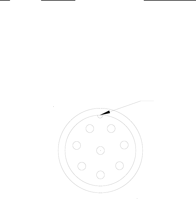
3. Pin out Description
Following is the pin out for the DS4 circular output connector (male bulkhead
connector on the module) with the mating cable wire colors:
Pin Description Cable Wire Color
1 +13.6 VDC Input Red
2 OFF/ (Gnd to turn unit off) White
3 RS232 Rec Line (not used) Blue
4 RS232 Trans Line Brown
5 Signal Gnd Green
6 No Connection Orange
7 No Connection Yellow
8 Power Ground Black
DS4 CONNECTOR PIN DEFINITION
Guide Key
0
1
2
3
4
5
6
7
8
6
MPH INDUSTRIES, INC.
A SUBSIDIARY OF MPD, INC.
316 EAST NINTH STREET
OWENSBORO, KY 42303
1-888-689-9222
FAX: (270) 685-6288
HOURS: MONDAY-FRIDAY
8:00AM – 4:30PM (Central Time Zone)
Part No. 990947, Rev -
Date: May 2005