M SYSTEM 0000001 WIRELESS GATEWAY User Manual 05
M-SYSTEM CO., LTD. WIRELESS GATEWAY 05
UserManual.wiki
>
M SYSTEM
>
0000001 User Manual
05 User Manual
Navigation menu
Upload a User Manual
Namespaces
Wiki Guide
HTML
PDF
Info
Views
User Manual
Discussion / Help
Navigation
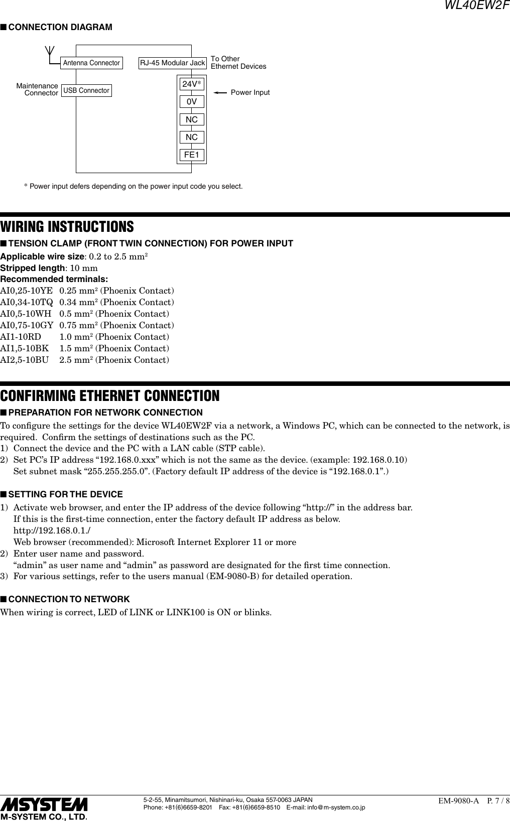
![WL40EW2F5-2-55, Minamitsumori, Nishinari-ku, Osaka 557-0063 JAPANPhone: +81(6)6659-8201 Fax: +81(6)6659-8510 E-mail: info@m-system.co.jpEM-9080-A P. 6 / 8TERMINAL CONNECTIONSConnect the unit as in the diagram below. ■EXTERNAL DIMENSIONS unit: mm (inch)105 (4.13)[260 (10.24)]60 (2.36) 107 (4.21)107 (4.21)3 (.12)3 (.12)45 (1.77)[200 (7.87)]20(.79)approx. 2500 (98.4)ø27(1.06)ø3 (.12)ø1.2 (.05)36 (1.42)80 (3.15)5 (.20)[155 (6.10)] [R165 (6.50)] • With sleeve antenna• With rooftop antennaDIN RAIL35mm wideDIN RAIL35mm wide8 (.31) Hex.](https://usermanual.wiki/M-SYSTEM/0000001/User-Guide-3815024-Page-6.png)