M Tec Trackunit A S ME401 Mobile Engine User Manual Userguide ME401 v1 3a US v4
M-Tec Trackunit A/S Mobile Engine Userguide ME401 v1 3a US v4
User Guide
ME401-2
Technical Manual
Version 1.3a, September 2012

ME401-2
M-Tec ME401-2, Technical Manual v.1.3a, September 2012 Page 2
Content
Content .......................................................................................................... 2
Related Information .......................................................................................................... 5
Safety first...................................................................................................... 5
Simple Guidelines ............................................................................................................ 5
Detailed Safety Information ............................................................................ 6
Exposure to Radio Frequency Signals ............................................................................. 6
Delivered standard content ............................................................................ 9
Practical installation advice ............................................................................................ 10
Connections ................................................................................................................... 10
Power supply .............................................................................................................. 10
Digital inputs ............................................................................................................... 11
Digital output ............................................................................................................... 11
Motion sensor ............................................................................................................. 11
1-Wire input ................................................................................................................ 11
Installation of the ME401-2 in machinery ..................................................... 12
Installation of the ME401-2 in vehicles ......................................................... 13
Functionality check ...................................................................................... 14
LED ................................................................................................................................ 14
Status SMS Commands ................................................................................................. 14
Installation of the digital output .................................................................... 17
SMS commands for output control ................................................................................. 18
Safety precautions.......................................................................................................... 18
Warranty ...................................................................................................... 19
Technical Assistance ................................................................................... 19
Minimum Information Required for Technical Assistance ............................................... 19
Complaints ..................................................................................................................... 20
Specifications .............................................................................................. 21
Product specifications .................................................................................................... 21
Connections: ............................................................................................................... 21
Temperature range: .................................................................................................... 21
GSM/GPRS-specifications: ......................................................................................... 21
Mechanical specifications ........................................................................................... 21
Approvals and certificates ............................................................................ 22

ME401-2
M-Tec ME401-2, Technical Manual v.1.3a, September 2012 Page 3
Corporate Office
M-Tec A/S
Industrivej 10
9490 Pandrup
Denmark.
www.m-tec.dk
www.trackunit.com
Copyright and Trademarks
© 1998-2011, M-Tec A/S. All rights reserved. M-Tec, the red
M hyphen TEC logo, Trackunit and Trackunit Pro are
trademarks of M-Tec A/S, registered in the United States and
in other countries. All other trademarks are the property of
their respective owners.
Release Notice
This document is release 1.3 of the ME401-2, Technical
Manual.
THIS MANUAL IS INTENDED FOR USE BY SYSTEM
INTEGRATORS, SERVICE PROVIDERS AND
APPLICATION DEVELOPERS (COLLECTIVELY,
“RESELLERS”). IT IS NOT INTENDED FOR END-USERS
OF THE ME401. ANY END-USER DOCUMENTATION IS
TO BE PREPARED AND FURNISHED BY THE
RESELLERS.
The following Product Limited Warranty gives Resellers
specific legal rights. You may have others, which vary from
state/jurisdiction to state/jurisdiction.
Product Limited Warranty
Subject to the terms and conditions set forth herein, M-Tec
A/S (“M-Tec”) makes the following warranty only to its
Resellers who purchase the ME401 hardware product
(“Product”) directly from M-Tec: for a period of one (1)
year from the date of shipment from M-Tec, the Product will
substantially conform to M-Tec’s standard published
specifications for the Product and the Product hardware will
be substantially free from defects in materials and
workmanship. The foregoing warranty shall not apply to
embedded software/firmware components.
THIS PRODUCT LIMITED WARRANTY IS PROVIDED TO
RESELLERS AND TO RESELLERS ONLY. RESELLER IS
SOLELY RESPONSIBLE FOR ANY AND ALL
WARRANTIES MADE TO ITS CUSTOMERS, AND M-TEC
MAKES NO WARRANTIES, EXPRESS OR IMPLIED, AND
SHALL HAVE NO OBLIGATIONS OR LIABILITY TO
RESELLER’S CUSTOMERS OR END-USERS OF THE
PRODUCT. RESELLER SHALL NOT
MAKE ANY REPRESENTATIONS OR WARRANTIES ON
M-TEC’S BEHALF, AND SHALL FULLY INDEMNIFY,
DEFEND AND HOLD M-TEC HARMLESS FROM ANY
BREACH OF THE FOREGOING. IF RESELLER
DISTRIBUTES PRODUCT TO END-USER CUSTOMERS,
RESELLER SHALL BE SOLELY RESPONSIBLE FOR
PREPARING AND PROVIDING PRODUCT WARRANTIES
AND PRODUCT LITERATURE TO END-USERS.
Warranty Remedies
If the Product fails during the warranty period for reasons
covered by this Product Limited Warranty and Reseller
notifies M-Tec of such failure during the warranty period, M-
Tec at is option will repair OR replace the nonconforming
Product, OR refund the purchase price paid by Reseller for
the Product, provided that Reseller returns the Product to M-
Tec in accordance with M-Tec’s standard return material
authorization procedures or as otherwise instructed by M-
Tec.
Warranty Exclusions and Disclaimers
The foregoing Product Limited Warranty shall only apply in
the event and to the extent that (i) the Product is properly and
correctly installed, configured, interfaced, maintained, stored
and operated in accordance with M-Tec’s specifications, and
(ii) the Product is not modified or misused. This Product
Limited Warranty shall not apply to, and M-Tec shall not be
responsible for, defects or performance problems resulting
from: (a) the combination or utilization of the Product with
hardware or software products, information, data, systems,
interfaces, services or devices not made, supplied or specified
by M-Tec; (b) the operation of the Product under any
specifications other than, or in addition to, M-Tec’s standard
published specifications for the Product; (c) the unauthorized
installation, modification or use of the Product; (d) damage
caused by: accident, lightning or other electrical discharge,
water immersion or spray, or exposure to environmental
conditions for which the Product is not intended; or (e)
normal wear and tear on consumable parts, including by way
of example and without limitation, batteries.
M-TEC DOES NOT WARRANT OR GUARANTEE THE
RESULTS OBTAINED THROUGH THE USE OF THE
PRODUCT. THE FOREGOING TERMS OF THE PRODUCT
LIMITED WARRANTY STATE M-TEC’S ENTIRE
LIABILITY, AND RESELLER’S EXCLUSIVE REMEDIES,
RELATING TO THE USE AND PERFORMANCE OF THE
PRODUCT EXCEPT AS OTHERWISE EXPRESSLY
PROVIDED FOR IN THIS PRODUCT LIMITED
WARRANTY, THE PRODUCT, ACCOMPANYING
DOCUMENTATION AND MATERIALS, AND/OR ANY
EMBEDDED SOFTWARE/FIRMWARE AND UPDATES
THERETO ARE PROVIDED “AS-IS” AND WITHOUT
EXPRESS OR IMPLIED WARRANTIES OF ANY KIND, BY
EITHER M-TEC OR ANYONE WHO HAS BEEN INVOLVED
IN ITS CREATION, PRODUCTION, INSTALLATION OR
DISTRIBUTION, INCLUDING, BUT NOT LIMITED TO,
THE IMPLIED WARRANTIES OF MERCHANTABILITY
AND FITNESS FOR A PARTICULAR PURPOSE, TITLE
AND NONINFRINGEMENT. THE STATED EXPRESS
WARRANTIES ARE IN LIEU OF ALL OBLIGATIONS OR
LIABILITIES ON THE PART OF M-TEC ARISING OUT
OF, OR IN CONNECTION WITH, THE PRODUCT.
WITHOUT LIMITING THE GENERALITY OF THE
FOREGOING:
M-TEC IS NOT RESPONSIBLE FOR THE OPERATION OR
FAILURE OF OPERATION OF GPS SATELLITES OR
WIRELESS SERVICE OR THE AVAILABILITY OF GPS
SATELLITE SIGNALS OR WIRELESS SERVICE. THE
PRODUCT MAY CONTAIN TECHNOLOGY THAT IS NOT
FAULT TOLERANT AND IS NOT DESIGNED,
MANUFACTURED OR INTENDED FOR USE IN
ENVIRONMENTS OR APPLICATIONS IN WHICH THE
FAILURE OF THE PRODUCT WOULD LEAD TO DEATH,
PERSONAL INJURY OR SEVERE PHYSICAL OR
ENVIRONMENTAL DAMAGE OR SEVERE FINANCIAL
LOSS. ANY USE OR DISTRIBUTION BY RESELLER OR
ITS CUSTOMERS IN CONNECTION WITH ANY SUCH

ME401-2
M-Tec ME401-2, Technical Manual v.1.3a, September 2012 Page 4
ENVIRONMENT OR APPLICATION SHALL BE AT
RESELLER’S AND ITS CUSTOMERS’ SOLE RISK, AND M-
TEC SHALL HAVE NO LIABILITY WHATSOEVER IN
CONNECTION THEREWITH. RESELLER SHALL
INDEMNIFY AND HOLD M-TEC AND ITS SUPPLIERS
HARMLESS FROM ANY CLAIM BROUGHT AGAINST M-
TEC WHICH ARISES FROM RESELLER’S USE OR
DISTRIBUTION OF THE PRODUCT IN CONNECTION
WITH SUCH ENVIVRONMENTS OR APPLICATIONS.
SOME STATES AND JURISDICTIONS DO NOT ALLOW
LIMITATIONS ON DURATION OR THE EXCLUSION OF
AN IMPLIED WARRANTY, SO CERTAIN OF THE ABOVE
LIMITATIONS MAY NOT APPLY TO EVERY RESELLER.
Embedded Software/Firmware
The Product and associated tools, if any, may contain
embedded software/firmware, which is licensed, not sold, and
is only for use within the Product as an integral part thereof.
Such embedded software/firmware (which includes all
updates thereto) contains valuable trade secrets and is
proprietary to M-Tec and its suppliers. To the greatest extent
permitted by law, such embedded software/firmware may not
be modified, copied, disassembled, decompiled or reverse
engineered. M-Tec reserves all other rights.
Limitation of Liability
M-TEC’S ENTIRE LIABILITY REGARDING THE PRODUCT
SHALL BE LIMITED TO THE AMOUNT ACTUALLY PAID
BY RESELLER FOR THE PRODUCT. TO THE MAXIMUM
EXTENT PERMITTED BY APPLICABLE LAW, IN NO
EVENT SHALL M-TEC OR ITS SUPPLIERS BE LIABLE
FOR ANY INDIRECT, SPECIAL, INCIDENTAL OR
CONSEQUENTIAL DAMAGES WHATSOEVER UNDER
ANY CIRCUMSTANCE OR LEGAL THEORY RELATING IN
ANY WAY TO THE PRODUCTS, ACCOMPANYING
DOCUMENTATION AND MATERIALS, AND ANY
EMBEDDED SOFTWARE/FIRMWARE AND UPDATES
THERETO (INCLUDING, WITHOUT LIMITATION,
DAMAGES FOR LOSS OF BUSINESS PROFITS,
BUSINESS INTERRUPTION, LOSS OF DATA OR ANY
OTHER PECUNIARY LOSS), REGARDLESS OF WHETHER
M-TEC HAS BEEN ADVISED OF THE POSSIBILITY OF
ANY SUCH LOSS AND REGARDLESS OF THE COURSE
OF DEALING BETWEEN M-TEC AND RESELLER.
BECAUSE SOME STATES AND JURISDICTIONS DO NOT
ALLOW THE EXCLUSION OR LIMITATION OF LIABILITY
FOR CONSEQUENTIAL OR INCIDENTAL DAMAGES, THE
ABOVE LIMITATION MAY NOT APPLY TO EVERY
RESELLER.
Notices
Class B Statement – Notice to Users. This equipment has
been tested and found to comply with the limits for a Class B
digital device, pursuant to Part 15 of the FCC rules. These
limits are designed to provide reasonable protection against
harmful interference in a residential installation. This
equipment generates, uses, and can radiate radio frequency
energy and, if not installed and used in accordance with the
instructions, may cause harmful interference to radio
communication. However, there is no guarantee that
interference will not occur in a particular installation. If this
equipment does cause harmful interference to radio or
television reception, which can be determined by turning the
equipment off and on, the user is encouraged to try to correct
the interference by one or more of the following measures:
– Reorient or relocate the receiving antenna.
– Increase the separation between the equipment and the
receiver.
– Connect the equipment into an outlet on a circuit different
from that to which the receiver is connected.
– Consult the dealer or an experienced radio/TV technician
for help.
Changes and modifications not expressly approved by the
manufacturer or registrant of this equipment can void your
authority to operate this equipment under Federal
Communications Commission rules.
Regulatory Approvals
CE
The ME401 products comply with the essential requirements
of the R&TTE Directive 1999/5/EC as stated by the EC
Declaration of Conformity (CE0682). The ME401 products
comply with the European Telecommunications Standards
Institute Specifications EN 301 489-1 (EMC for GSM
900MHz and DCS 1800MHZz Radio Equipment and
Systems).
EEC/ International
The ME401 products comply with the essential requirements
of the Automotive directive 2004/104/EC clause 6.5, 6.6, 6.8
and 6.9, UN regulative ECE R10 EMC rev3.
The ME401 products comply with the essential requirements
of the Directive 2003/37/EEC and Directive 2006/42/EEC.
The ME401 products comply with the international standards
ISO-13309, ISO13766 and EN ISO-14982, for tractors, forest
and agricultural machinery, moving machinery and
construction machinery.
The ME401 product comply with the essential and
environmental requirements for use on rolling stock
according to ISO 50121-3-2 and DIN EN 50125-1.
FCC
The ME401 products comply with the FCC Part 15, Part 22
and Part 24, and Industry Canada requirements. The ME401
products comply with Part 15 of the FCC rules. Operation is
subject to the following two conditions: (1) This device may
not cause harmful interference, and (2) This device must
accept any interference received, including interference that
may cause undesired operation.
For fixed mounted operations the ME401 must be installed to
provide a separation distance of at least 5 cm from all
persons.
ME401:
FCC ID: ZMF-ME401
IC-ID: 9746A-ME401

Introduction
This document contains the installation guide for the GSM/GPS product type series ME
401-2 units. This manual is intended for use by system integrators, service providers and
application developers (collectively, “Resellers”). It is not intended for end-users of the
ME401-2. Any end-user documentation is to be prepared and furnished by the Resellers.
This manual covers the ME401-2 with 59.2 and later firmware and operating on 850 MHz,
900 MHz, 1800 MHz and 1900 MHz Global System for Mobile communication (GSM)
networks. Data and Event Reporting support is by Short Message Service (SMS), General
Packet Radio Service (GPRS), or both.
This manual describes how to set up, configure, install, operate, and troubleshoot the
product. Even if you have used other GSM or Global Positioning System (GPS) products
before, M-Tec recommends that you spend some time reading this manual to learn about
the special features of this product.
M-Tec assumes that you are familiar with Microsoft Windows.
This manual is available in portable document format (PDF) from the following web site:
www.trackunit.com . Alternatively the latest version of this manual can also be downloaded
from the factory website:
http://www.m-tec.dk
Related Information
The Trackunit Pro web site is found at www.trackunit.com. This site is dedicated to the
fleet management system from M-Tec A/S called Trackunit Pro. ME401-2 devices are
integrated to Trackunit Pro but can also be used together with third part system providers.
Safety first
Simple Guidelines
Please follow these guidelines when configuring, using or recycling the ME401. Violating
these guidelines may be dangerous, illegal or otherwise detrimental. Further detailed
information is provided in this manual.
Do Not Operate Where Prohibited
Do not allow the ME401 unit to operate wherever wireless phone use is prohibited or when
doing so may cause interference or danger. The ME401 cannot be turned off after
installation, so any vehicle, moving machinery, construction machinery using ME401 etc.
must not enter areas where it is prohibited to operate wireless phones.
Examples include but are not limited to operation in hospitals, aircrafts, near blasting sites
or wherever operation can cause interference.

ME401-2
M-Tec ME401-2, Technical Manual v.1.3a, September 2012 Page 6
Interference
Like all wireless devices, the ME401 may encounter electrical interference that may affect
its performance.
Avoid Body Contact with Device during Operation
Do not operate the ME401 in direct contact with your body. Maintain at least 2 inches (5
cm) separation between the device and any parts of your body.
Qualified Service
Except for batteries and Subscriber Identification Module (SIM) card, the ME401 contains
no user serviceable or replaceable parts. Non-functioning units must be returned to an
authorized service center for repair or replacement.
Accessories and Batteries
Use only approved accessories or batteries. Do not connect incompatible products.
There is risk of explosion or fire if an incorrect type replacement battery contacts are
shorted. Do not exceed the temperature ranges or other environmental conditions
specified by the battery manufacturer. Dispose of used batteries according to the
instructions provided with the batteries.
Water-Resistance
The ME401 series is water-resistant according to the IP-67 standard. It is however
recommended that it is be used where it is relatively dry and not subjected to either water
streams or submersion.
Recycling
For information on how to recycle this product in the European Union, go to either web
page www.trackunit.com or www.m-tec.dk.
Detailed Safety Information
Exposure to Radio Frequency Signals
The ME401 unit is a low power radio transmitter and receiver. When it is ON, it receives
and also sends out radio frequency (RF) signals. The ME401 unit cannot be turned off
after installation, so the unit operates in an always ON mode, for approximately of 3
to 4 days depending on the charging state of the backup battery.
The ME401 unit is not designed to be worn on a person’s body.
Electronic Devices
Most modern electronic equipment is shielded from RF signals. However, certain
electronic equipment may not be shielded against the RF signals generated by the ME401
unit.
Pacemakers
The Health Industry Manufacturers Association recommends that a minimum separation of
six (6”) inches be maintained between a handheld wireless phone and a pacemaker to
avoid potential interference with the pacemaker. The following precautions apply:
• The ME401 unit is not intended for handheld use or to be worn on the body.

ME401-2
M-Tec ME401-2, Technical Manual v.1.3a, September 2012 Page 7
• It is recommended that a minimum separation of ten (8”) inches (20 cm) is to be
maintained between the ME401 unit and any persons’ body at all times. The device
is SAR tested and approved for a separation distance of only (2") inches (5 cm)
between the ME401 and any person’s body.
• Do not carry the ME401 on your person.
Other Medical Devices
If any other personal medical devices are used in the vicinity of a ME401 unit, consult the
manufacturers of the medical devices to determine if they are adequately shielded from
external RF energy. Physicians may be able to assist in obtaining this information.
The ME401 unit cannot be turned off after installation, so any vehicle, moving machinery,
construction machinery installed with the ME401 etc. must not operate near health care
facilities when any regulations posted in these areas prohibit the use of wireless phones or
two-way radios. Hospitals and health care facilities may be using equipment that could be
sensitive to external RF energy.
Vehicles
RF signals may affect improperly installed or inadequately shielded electronic systems in
motor vehicles. Check with the manufacturer or its representative regarding the vehicle.
Also consult the manufacturer of any equipment that has been added to the vehicle.
Posted Facilities
The ME401 unit cannot be turned off after installation, so any vehicle, moving machinery,
construction machinery installed with the ME401 etc. must not enter any facility where
posted notices prohibit the use of wireless phones or two-way radios.
Aircrafts
FCC and FAA regulations prohibit using wireless phones while in the air. Do not carry the
ME401 unit aboard an aircraft as it cannot be turned off.
The ME401 unit cannot be turned off after installation, so any vehicle, moving machinery,
construction machinery installed with the ME401 etc. must not enter a “blasting area” or in
areas posted “turn off two way radio” to avoid interfering with blasting operations. Obey all
signs and instructions.
Potentially Explosive Atmospheres
The ME401 unit cannot be turned off after installation, so any vehicle, moving machinery,
construction machinery installed with ME401 etc. must not enter any area with a potentially
explosive atmosphere and obey all signs and instructions. Sparks in such areas could
cause an explosion or fire resulting in bodily injury or even death.
Areas with a potentially explosive atmosphere are often, but not always marked clearly.
Potential areas may include: fueling areas (such as gasoline stations); below deck on
boats; fuel or chemical transfer or storage facilities; vehicles using liquefied petroleum gas
(such as propane or butane); areas where the air contains chemicals or particles (such as
grain, dust, or metal powders); and any other area where it would normally be advisable to
turn off motor vehicle engines it is not allowed to enter with a vehicle, moving machinery,
construction machinery installed with the ME401.

ME401-2
M-Tec ME401-2, Technical Manual v.1.3a, September 2012 Page 8
For Vehicles Equipped with an Airbag
An airbag inflates with great force. DO NOT place objects, including the ME401 unit, in the
area over the airbag or in the airbag deployment area. If in vehicle wireless equipment is
improperly installed and the air bag inflates, serious injury could result.
Specific Absorption Rates (SAR)
THE ME401 UNIT IS NOT DESIGNED TO BE WORN ON A PERSON’S BODY.
AS SUCH, BODY WORN TEST POSITIONS FOR THE ME401 UNIT
ARE NOT REQUIRED BY EITHER THE EN50360/1 FOR GSM 900/1800 BANDS OR
FCC REQUIREMENTS FOR GSM 850/1900 BANDS.
The ME401 unit is not intended for handheld use or to be worn on the body. A minimum
separation of ten (2”) inches (5 cm) is to be maintained between the ME401 and any
persons’ body. Additional information on Specific Absorption Rates (SAR) can be found on
the Cellular Telecommunications & Internet Association (CTIA) Web site at www.ctia.org.
Battery Safety Information
Adhere to the following guidelines to avoid the risk of fire or explosion:
1. Dispose of the used battery according to the instructions provided with the battery.
2. Do not drop, puncture, disassemble, mutilate, or incinerate the battery.
3. Touching both terminals of a battery with a metal object will short circuit the battery. Do
not carry batteries loosely if the contacts may touch coins, keys, and other metal objects
(such as in pockets or bags).
4. Do not stack batteries taken out of the carry case.
5. Do not heat the batteries to try to rejuvenate their charge.
6. Do not exceed the temperature ranges or other environmental conditions specified by
the battery manufacturer.
7. Never use the ME401 without the battery cover installed.

ME401-2
M-Tec ME401-2, Technical Manual v.1.3a, September 2012 Page 9
Delivered standard content
The delivered standard package content includes the following items:
1 x GSM/GPS-unit of the model type ME401-2
1 x mounting cradle
1 x Li-ion Battery (May already be mounted inside the ME401-2 unit)
1 x Fuse with fuse holder
In case the unit is delivered with SIM card from the factory, then the GSM number will
be indicated on the delivery note as well as on the package itself.
NOTE: In case the SIM card is delivered from factory it is mounted inside the ME401-2
unit.
Ready-to-Use, No Custom Programming Required
Simply connect the unit to supply voltage (12V/24V DC). In its default configuration,
reports are sent nominally at 15-minute intervals or faster whenever there is motion.
Upon powering up, the device will self-initialize anywhere in the world and start
transmitting if an authorized GSM network is available. While a basic understanding of the
different ME401-2 operational states is helpful, configuring the ME401-2 unit does not
require a highly skilled software programmer or technician.
Cost-effective, Universally Available Communications
The ME401-2 unit takes advantage of the near universal availability of GSM SMS text
messaging while also leveraging cost-effective GPRS data rate plans. Typical SMS plans
offer very extensive inter-network roaming capabilities, both within a host country and
internationally.
SMS plans also tend to be too pricey for applications requiring more than a few reports per
day. GPRS data plans, on the other hand, typically allow for lower recurring
communication costs although GPRS coverage and roaming can be restricted in some
areas.
The ME401-2 unit takes advantage of both technologies by automatically selecting GPRS
wherever such service is available, while relying upon SMS text messages for
configuration purpose only. This helps minimize recurring communication costs while
allowing the greatest coverage possible.

ME401-2
M-Tec ME401-2, Technical Manual v.1.3a, September 2012 Page 10
Installing the unit
Practical installation advice
• It is very important to be careful when installing the unit, as incorrect
installation will reduce the quality of the GPS position reports (Ex. could be a
jump in position or showing speed while parking) or in the worst case
scenario will prevent the unit performing any position reporting at all.
The unit must NOT be installed beneath metal plates or inside closed metal
compartments. Incorrect installation will also reduce the standby time of the
battery inside the unit.
•
The unit must be mounted either horizontally or vertically (sideways) using either
screws or strips. The unit must not be installed with the interface/supply cable
hanging down, as this definitely will reduce the GPS sensitivity.
Optimize the placement of the unit to increase the aerial view (through windows
etc.) as much as possible. For hiding the unit, make sure it is only mounted beneath
plastic parts or similar parts (wood), but not beneath metal parts.
•
To reduce hum and noise in the FM radio it is recommended to place the unit at a
minimum distance of 20 inches (50 cm) from the radio or the loudspeakers.
Connections
The connections depend on the type of vehicles / machines etc. in which the GSM/GPS
unit is to be installed. In the table below the possible connections are listed for the ME401-
2 device.
The connections may differ for other variants of the ME401 device. Please contact your
nearest sales office, distributor or “Reseller” for further information about the availability of
other variants in your area.
No.
Wire
(color code)
ME401
-
2
function
1 Red Supply voltage +12V / +24V
2 White Digital input 1
3 Brown Digital input 2 Ignition
4 Grey Digital input 3 / ID06
5 Pink Digital input 4
6 Green 1-Wire input
7 Yellow Digital output 1
8 Blue Common ground
Power supply
The unit must be connected to either +12V or +24V battery voltage through a 1 amp. fuse.
The use of a fused supply wire is important for not damaging the wires related to the unit in
case of a short circuit etc.

ME401-2
M-Tec ME401-2, Technical Manual v.1.3a, September 2012 Page 11
Digital inputs
The activation of a digital input requires a minimum high level voltage of 8V.
Digital output
The digital output has the type indication ”LO-side switch”, that connects the output to 0V
“ground”, when the output is active. This output can be used to control a relay powered
from an external DC supply voltage. The maximum current drawn from the output is
200mA and the voltage from the external supply voltage must not exceed 40V DC.
The output is protected against short circuits, overload and is also protected against over
voltage. For further information about connection possibilities of the digital output, see
chapters about installation later in this manual.
Motion sensor
The unit has a built-in motion sensor that is able to activate the unit if it, as a consequence
of disconnected supply voltage, is in stand-by mode. When motion is detected it will also
cause activity on ‘Input 3’ on the Trackunit portal.
1-Wire input
The 1-wire (Green wire) is designed to communicate with temperature sensors based on
the DS18B20 or DS18S20 sensor.
The 1-wire input can also be used to read Dallas iKey for access control.
The 1-wire input is only operational when supply voltage (12V / 24V) is present.
It cannot operate on internal battery alone.
ME401-2
M-Tec ME401-2, Technical Manual v.1.3a, September 2012 Page 12
Installation of the ME401-2 in machinery
In this section possible installation proposals are given. The installation proposals are
listed as examples and can be used as a guide for inspiration for an actual installation.
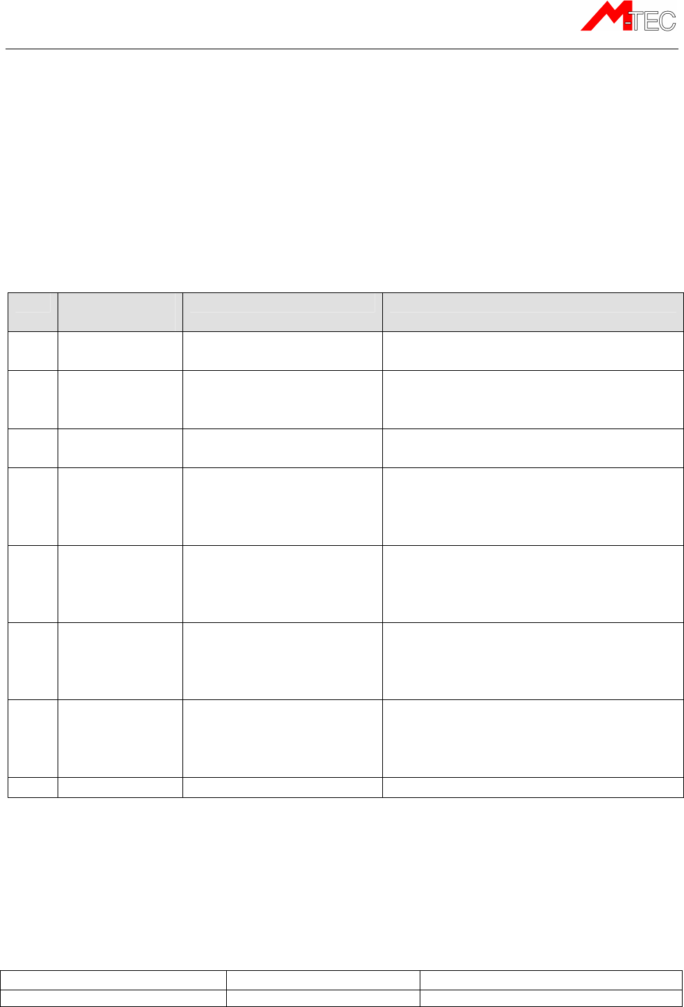
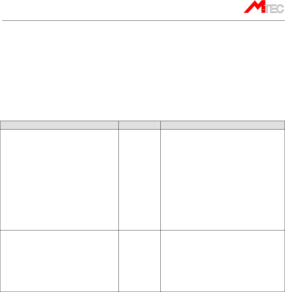
Standard installation of ME401-2 for registering operating hours:
For a standard installation in machines where the unit should register the number of
operating hours use the connections as follows:
No
.
Wire
(color code)
Connection
Description
1 Red Power Connect to a fixed DC supply through
a fuse of 1 Amp.
2 White Digital input 1 Connect to the operating hours
counter.
(Min. 8V DC voltage at the input)
3 Brown Digital input 2 Connect to the ignition signal
(Min. 8V DC voltage at the input)
4 Grey Digital input 3 Can be connected to an external
sensor or it can be connected to a
ID06 Card reader.
(Min. 8V DC voltage at input)
5 Pink Digital input 4 Can be connected to an external
sensor for detecting a critical running
mode or an alarm
(Min. 8V DC voltage at input)
6 Green 1-wire input Can be used to connect one or two
temperature sensors or a Dallas Key
reader to control an immmobilizer
relay connected to Digital output 1
7 Yellow Digital output 1 Can be used to control external
equipment through a relay (see
example in “Installation of the digital
output”. Max. Load 200 mA)
8 Blue Ground
Installing the ME401-2 as to surpass the main switch on the machine:
In case the main switch on the machine will break the negative wire (Ground wire), the
inputs may register a voltage level and start counting operating hours. To avoid this
situation the digital input 4 (Pink wire) should be connected to the chassis/ground on the
machine. Then send the following SMS to the unit (phone number) to activate the filtering:
Function
Send SMS
Return
-
SMS from the unit
Activate filter function on inputs. MT INFILT ON MTC ACK (SERIAL No.) INFILT ON
ME401-2
M-Tec ME401-2, Technical Manual v.1.3a, September 2012 Page 13
NOTE: Enabling the filtering function will disable the use of the alarm function on digital
input 4 as listed in the standard installation proposal above.
NOTE: It is recommended always to connect digital input 2 to the ignition signal of the
machine as this is necessary for km recording.
NOTE: For the “Send SMS” it is of no importance if small or capital letters are used in
the command string, or a mixture hereof.
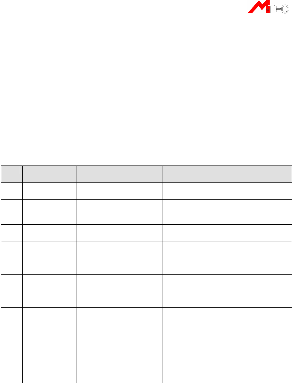
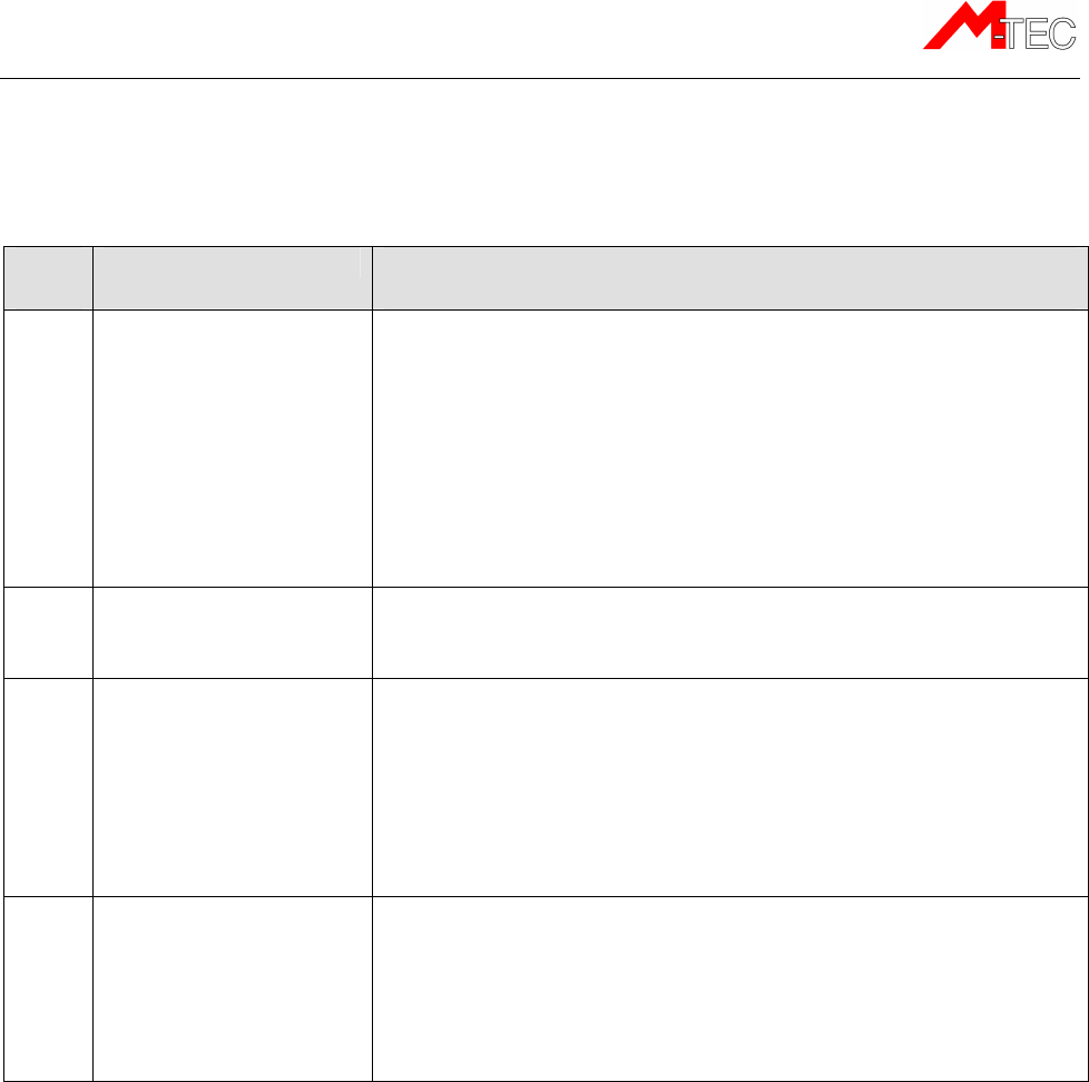
Installation of the ME401-2 in vehicles
The standard installation for vehicles, where the unit should register operating hours and
record km, the following connections are used:
No
.
Wire
(color code)
Connection
Description
1 Red Power Connect to a fixed DC supply through
a 1 amp. fuse.
2 White Digital input 1 Connect to the operating hours
counter.
(Min. 8V DC voltage at the input)
3 Brown Digital input 2 Connect to the ignition signal
(Min. 8V DC voltage at the input)
4 Grey Digital input 3 Can be connected to an external
sensor or it can be connected to a
ID06 Card reader.
(Min. 8V DC voltage at input)
5 Pink Digital input 4 Can be connected to an external
sensor for detecting a critical running
mode or an alarm
(Min. 8V DC voltage at input)
6 Green 1-wire input Can be used to connect one or two
temperature sensors or a Dallas Key
reader to control an immobilizer relay
connected to Digital output 1
7 Yellow Digital output 1 Can be used to control external
equipment through a relay (see
example in “Installation of the digital
output”. Max. Load 200 mA)
8 Blue Ground
NOTE: It is recommended always to connect digital input 2 to the ignition signal of the
vehicle as this is necessary for km recording.
ME401-2
M-Tec ME401-2, Technical Manual v.1.3a, September 2012 Page 14
Functionality check
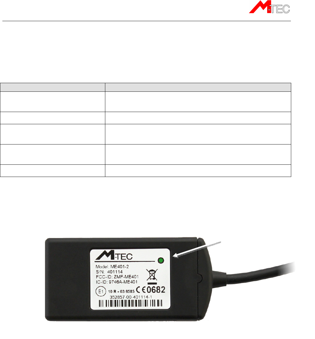
LED
The ME401-2 is fitted with an LED that has the following status indications:
LED
mode
Status indication
A constant green light shortly
interrupted by a red blink:
The unit is attached to the GSM network and the GPS is
navigating – Everything is OK.
No light: The unit is not connected to a power supply
Constant red light: The unit is powered up, but is not yet attached to the
GSM network
Short red blink: The unit is powered up and it is attached to the GSM
network, but is not yet navigating
Constant green light: The unit is navigating (GPS-satellite position fix)
LED
ME401-2
M-Tec ME401-2, Technical Manual v.1.3a, September 2012 Page 15
Status SMS Commands
In order to control if the installation of the ME401-2 unit has been done correctly, it is
possible to send one or more check SMS messages to the GSM phone number allocated
to the unit.
Please wait 1 minute after applying the power to the unit before attempting to send any
SMS messages to the unit.
An overview of the SMS message commands for functionality check is given below:
Check
Send SMS
Retur
n
SMS
from uni
t
• Is the unit powered up?
• Does the GPS receiver have
sufficient reception conditions?
• Is the GSM signal coverage
sufficient?
NOTE:
It is best to perform this check
under outdoor conditions as any
buildings/garage would reduce signal
quality.
MT SIGNAL
MTC ACK (SERIAL No.) SIGNAL: GSM=22,
SAT=8, SN=44
”GSM” is a measure for the quality of the
GSM coverage. The value should be at least
10. Maximum value for GSM coverage is 31.
”SAT” is a measure for the number of GPS
satellites visible to the GPS receiver.
Operational minimum is 3 and the best
operation is obtained from 6 and up.
”SN” is a measure for the GPS-signal
strength. Should be larger than 35.
• Are the digital inputs mounted
correctly
NOTE:
This command can be send to
the unit under various operational
conditions like: Machine running,
ignition only or off.
MT STAT
MTC ACK (SERIAL No.) INPUT STATUS:
INPUT1 LOW, INPUT2 LOW, INPUT4 LOW,
CHARGE VOLTAGE ON
NOTE:
An input is HIGH if there is more
than 8V on the input – otherwise it would
be LOW
NOTE: For the “Send SMS” it is of no importance if small or capital letters are used in
the command string, or a mixture hereof.
ME401-2
M-Tec ME401-2, Technical Manual v.1.3a, September 2012 Page 16
Troubleshooting
Various error situations are listed below along with some possible solutions.
Error
code
Error descrip
tion
Possible solutions
F1 The unit does not answer
the SMS command send
to it.
♦ Verify if the SMS messages are send to the correct GSM phone
number.
♦ Check LED status; See the “Functionality check” chapter in this
manual.
♦ If the ME401-2 unit has been delivered with the SIM card
mounted. Contact M-Tec support.
o Or contact the mobile operator to verify if there is any
problem with the SIM card.
♦ Verify if the SIM card is correctly mounted in the unit.
F2 The LED in the unit is off,
thus no power on the
unit.
♦ Check if the installation is performed correctly according to the
guidelines of this manual.
F3 The LED is constant red,
thus the unit is not
attached to the GSM
network
♦ If the ME401-2 unit has been delivered with the SIM card
mounted. Contact M-Tec support.
o Or contact the mobile operator to verify if there is any
problem with the SIM card.
♦ Verify if the SIM card is correctly mounted in the unit.
♦ Verify if the PIN code has been disabled from the SIM card before
it was inserted in the unit
F4 The unit send reply
messages but there is no
GPS signal
♦ Verify if the unit is mounted according to the instructions laid out
in this manual with respect to the aerial view; see “Installing the
unit” chapter.
♦ If the machine/vehicles are located inside a building, please move
the machine/vehicle outside a try again.
ME401-2
M-Tec ME401-2, Technical Manual v.1.3a, September 2012 Page 17
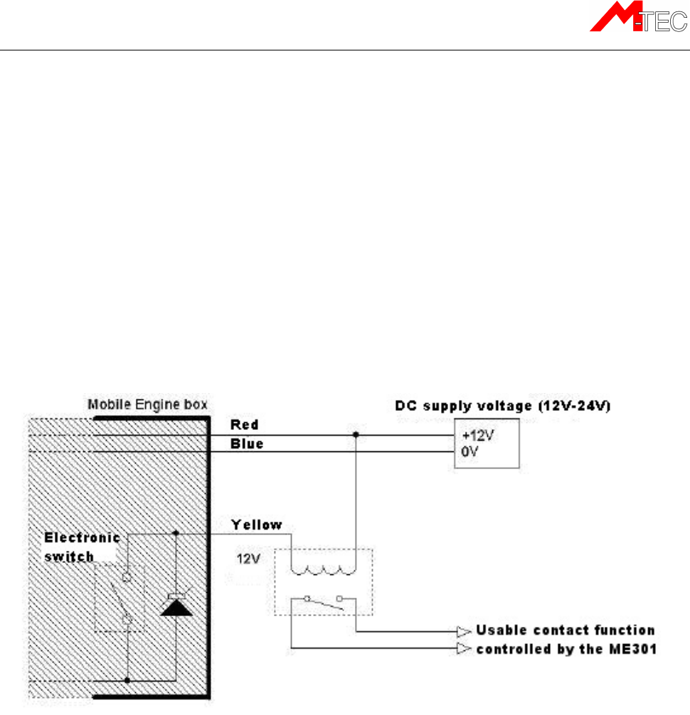
Installation of the digital output
According to the E1 certificate of the ME401-2 unit, it is prohibited under any
circumstances to use this output to control any equipment that may influence the safety of
the construction machinery and earth moving machines/vehicle operation and driving. The
output must only be used to control comfort equipment.
The example below shows a 12V relay function with a 12V DC supply voltage. It is also
possible to use a 24V relay with a 24V DC supply voltage. The current consumption of the
relay must not exceed 200 mA (DC current) and the relay contacts must be specified to
withstand the load that needs to be controlled.
NOTE: The output can only handle DC and not AC voltage. It is necessary to only use a
DC power supply for the relay.
Important!
The power supply connected to the ME401-2 GSM/GPS unit and
the supply voltage for the relay mounted on the digital output
must have a common ground connection.
One application example for the “Usable contact function controlled by the ME401-2”
signals shown in the figure above could be a “Start Relay”, blocking function, for
preventing unauthorized use of the moving machinery and construction machine or vehicle
outside normal working hours etc.

ME401-2
M-Tec ME401-2, Technical Manual v.1.3a, September 2012 Page 18
SMS commands for output control
Function
Send SMS
Return SMS
Description
Time controlled
activation of the
output
MT OUT1=1,30
MTC ACK (SERIAL No.)
OUT1 TIMER=1
MINUTES 30
SECONDS
With this command the output will be
activated for a number of defined minutes. In
the example 1 minute and 30 seconds was
used. The output is activated immediately
after the acknowledge SMS has been send
out and it is deactivated automatically when
the timer runs out.
NOTE:
It is possible to break the output before
the timer runs out by using the “OFF”
command.
Permanent
activation of the
output
MT OUT1=ON
MTC ACK (SERIAL No.)
OUT1 ON
With this command the output is activated
permanently. The output can be de-activated
again using the “OFF” command.
Deactivation of
the output
MT OUT1=OFF
MTC ACK (SERIAL No.)
OUT1 OFF
With this command the output is deactivated.
The command will work for any activation
mode either “time controlled” or “permanent”.
NOTE: For the “Send SMS” it is of no importance if small or capital letters are used in
the command string, or a mixture hereof.
Safety precautions
The use of the digital output is restricted to signals/systems/components related
to comfort applications in the vehicles.
Under no circumstances must it be used for purposes, which can influence the
safety of the vehicle when driving.
M-Tec holds no liability for any damages occurred to persons, vehicles, moving
machines, construction machines etc. caused by wrong installation and/or faulty
use of the digital output.

ME401-2
M-Tec ME401-2, Technical Manual v.1.3a, September 2012 Page 19
Warranty
M-Tec A/S products are covered by a limited manufacturer warranty. The M-tec A/S
warranty is limited to the warranty rules and legislation present in each country. The
warranty only covers manufacturing faults.
The warranty does not cover misuse, wrong installation or damage due to a faulty
installation or wrong maintenance.
The invoice act as the proof of warranty, so please keep it as reference for any warranty
complaints.
Technical Assistance
If you have a problem and cannot find the information you need in the product
documentation, please contact M-Tec A/S
M-Tec A/S
Industrivej 10
9490 Pandrup
Tel: +45 99 73 00 20
Fax: +45 96 73 74 07
E-mail:
support@m-tec.dk
http://www.m-tec.dk/en/
www.trackunit.com
When contacting technical support, please be prepared to provide the information listed
below:
Minimum Information Required for Technical Assistance
If you or a user reports difficulty with a ME401 unit (i.e. no GPS fixes, not communicating,
LED not working, etc.), it is helpful to retrieve directly from the unit all current configuration
settings and the message log data etc, that is accessible by the technical support when
they receive the following information about the unit.
1. Unit Serial number

ME401-2
M-Tec ME401-2, Technical Manual v.1.3a, September 2012 Page 20
Complaints
Return of faulty products must always be accompanied by a complaint note.
The template for returning complaints can be downloaded from the M-Tec website:
http://www.m-tec.dk/en/gsm_applications/rma/
If a returned product that was announced faulty, turns out not to have any errors when
tested at the factory, an examination invoice with a fee of DKR 250,- per product plus
return freight costs will be issued – not taken into consideration the original purchase
costs.
Try to make the error description as detailed as possible. Insufficient error descriptions will
extend the service time. The terms “Defective”, “Does not work”, “Dead” etc. are not
accepted as a detailed error description.
When the complaint note has been filled out, please send it to our service department. At
the following e-mail address:
service@m-tec.dk
Print out the complaint note and pack it together with the faulty product and send both to
the following address.
M-Tec A/S
Industrivej 10
DK-9490 Pandrup
Denmark
Attention: Service
ME401-2
M-Tec ME401-2, Technical Manual v.1.3a, September 2012 Page 21
Specifications
Product specifications
The ME401 unit is a GSM/GPRS quad-band-unit with GPS, integrated antennas and a
backup battery
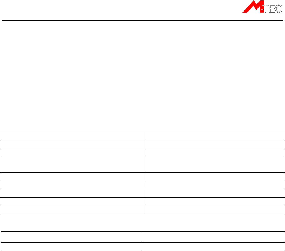
Connections:
Operational voltage (supply voltage): 12 - 24 V DC
Absolute maximum voltage range: 9 - 65 V DC
Standby consumption (GSM-receiver active) 20 mA / 10 mA (average, at 12V / 24V)
Consumption during charging on an empty
battery
225 mA / 115 mA (max, at 12V / 24V)
Standby time on the backup-battery 48 – 96 hours (Bad – optimum installation)
Charging time for an empty backup-battery 3 hours at 25 ºC
Expected lifetime of the backup-battery 3 years
Digital inputs Up to 6
Digital outputs Up to 2
Temperature range:
In active running mode -30ºC to +60ºC
Storage -40ºC to +70ºC
GSM/GPRS-specifications:
EGSM/GPRS/EGPRS 900/1800/850/1900
Maximum output power at EGSM-GPRS 900 MHz: 2.0W
Maximum output power at GSM-GPRS 850 MHz: 1.6W
Maximum output power at GSM-GPRS 1800/1900 MHz: 1.0W
GPRS-class 10 device
Mechanical specifications
Dimensions: Length: 92 mm
Width: 45 mm (49 mm incl. mounting cradle)
Height: 18 mm (23 mm incl. mounting cradle)
Cable length: 170 cm
Environmental class: IP67
Enclosure material: Non-flammable ABS
Weight: 63 g (excluding the cable)
ME401-2
M-Tec ME401-2, Technical Manual v.1.3a, September 2012 Page 22
Approvals and certificates
The ME401 product is certified according to the following recommendations:
FCC
The ME401 product complies with FCC Part 15, FCC Part 24, and Industry Canada
requirements.
The ME401 product complies with Part 15 of the FCC rules. Operation is subject to the
following two conditions:
(1) This device may not cause harmful interference, and
(2) This device must accept any interference received, including interference
that may cause undesired operation.
EEC/ International
• The ME401 product complies with the essential requirements of the Automotive
Directive 2004/104/EEC - UN regulative ECE R10 EMC rev. 3
• The ME401 product complies with the essential requirements of the Directive
2003/37/EEC and Directive 2006/42/EEC
• The ME401 product complies with the essential requirements of the R&TTE
directive 1999/05/EEC directive with respect to the EMC requirements, safety and
radio spectrum matters.
Including:
ISO 13309:2010 Construction machinery
ISO 13766:2006 Earth-moving machinery
EN/ISO 14982:2010 Agricultural and forestry machines
EN/IEC 60950-1:2009 +
A11, A1 and A12 ITE Safety
EN/ISO 50121-3-2:2006 EMC for apparatus on rolling stock
And environmental:
EN/IEC 60068-2-1:2007 Cold
EN/IEC 60068-2-2:2007 Dry Heat
EN/IEC 60068-2-27 Shock
EN/IEC 60068-2-64 Random vibration
EN/IEC 60068-2-78:2001 Damp heat steady state
FCC-ID: ZMF-ME401
IC-ID: 9746A-ME401
10
R – 03 6585

ME401-2
M-Tec ME401-2, Technical Manual v.1.3a, September 2012 Page 23
DIN EN 50125-1:2000 Railway – Environmental conditions for
equipment on rolling stock
CE
The ME401 product complies with the essential requirements of the R&TTE Directive
1999/5/EC as stated by the EC Declaration of Conformity.
Certificates and Declaration of conformity (DOC) statements can be downloaded from the
M-Tec website:
http://www.m-tec.dk/en/gsm_applications/certificates/