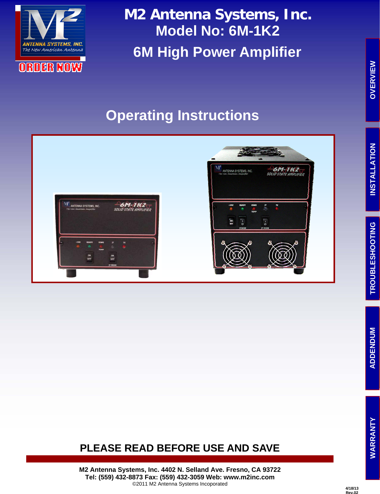
M2 ANTENNA SYSTEMS 6M-1K2 6M HIGH POWER AMPLIFIER User Manual 6M 1K2MAN03 PUB

M2 ANTENNA SYSTEMS INC. 6M HIGH POWER AMPLIFIER 6M 1K2MAN03 PUB

User Manual

    4/18/13 Rev.02 PLEASE READ BEFORE USE AND SAVE TROUBLESHOOTING  OVERVIEW INSTALLATION ADDENDUM WARRANTY M2 Antenna Systems, Inc. Model No: 6M-1K2  6M High Power Amplifier Operating Instructions M2 Antenna Systems, Inc. 4402 N. Selland Ave. Fresno, CA 93722 Tel: (559) 432-8873 Fax: (559) 432-3059 Web: www.m2inc.com ©2011 M2 Antenna Systems Incoporated
 2 CONTENTS          SECTION...........................................................PAGE  COVER PAGE ........................................................1 CONTENTS...........................................................2 OVERVIEW...........................................................3  Introduction.................................................3  Features ......................................................3  Major Components........................................4  Theory of Operation......................................6 INSTALLATION......................................................8  Typical Installation Diagram...........................8  Installation Considerations.............................8 TROUBLESHOOTING .............................................9  Troubleshooting Guide ..................................9   Support, Service and Returns ........................10 Schematic Diagram.......................................11 ADDENDUM..........................................................12  Parts List......................................................12  Specifications...............................................13   WSJT: What Is It and How Do I Get It?..........14 WARRANTY ..........................................................16  M2 Antenna Systems, Inc.  4402 N. Selland Ave. Fresno, CA 93722 Tel: (559) 432-8873 / Fax: (559) 432-3059  http://www.m2inc.com ©2011 M2 Antenna Systems Incoporated OVERVIEW
 3 OVERVIEW OVERVIEW It is with great satisfaction that M2 now offers a true breakthrough in high power VHF amplifiers.  Our goal has always been to offer the most carefully designed, high performance antenna products.  Now we offer the same high performance in VHF amplifiers.  The 6M-1K2 and the 2M-1K2 utilize the new Freescale™ LD MOS FET (MRFE6VP6IK25H), a single    device specified to produce 1.25 kW with as little as 3 watts of drive from HF to 600 MHz. This is amazing in itself, but adding its inherent stability driving that power into a 65:1 mismatch is equally incredible.  It can do all this at efficiencies well above 60%!   YOU CAN SEE WHY WE ARE EXCITED!  Here is where M2 comes in.  We wanted to make it small and we did; 6 x 7.125 x 13.5 inches (152 x 181 x 343 mm) so it will fit in a suitcase.  We wanted it to be light and it is at just 13 lbs (5.9 kg).  The optional integrated 2400 watt switching power supply adds only another 7.5 lbs to this incredible package that travels easily at 20.5 lbs (9.3 kg).  Additionally, the power supply may be purchased as a separate, stand alone accessory.  Now, at home in your shack you won’t need that big steel rack any more.  All you need is a small desktop or shelf to hold your QRO (high power) VHF amplifier.     Above all we made this amplifier easy to understand and operate.  The photo below shows the model with the amplifier and the power supply integrated together (7.125” wide, 9” high 14” deep). INTRODUCTION By now you may realize that there is a lot more in this amplifier package than just a 1.25 kW LDMOSFET.    What you can’t see in pictures is listed proudly below:  •  A complete and accurate high power VSWR bridge. •  Regulator PC board with high wattage power resistors and two voltage regulators. •  Medium power input power coaxial relay. •  High power, high speed vacuum relay easily capable of    handling full output power. •  Monitoring via high accuracy DC current and temperature monitoring devices. •  Sophisticated output RF filter reducing spurious harmonics to exceed FCC regulations. •  Quiet fan on the bottom cools miniature RF tank and filter components.  •  50 or 100 watt input attenuator that reduces your input power to safe drive levels. FEATURES Frescale™ is a registered trademark of Freescale Semiconductor, Inc.
 4 OVERVIEW MAJOR COMPONENTS, 6M-1K2  FRONT PANEL   1.  +50V LED (Yellow).  Indicates +50 VDC is present from the power supply 2.  Ready LED (Green). Lights when the Power switch is on and the amplifier is ready to be keyed and driven. 3.  VSWR/TEMP LED (Amber).  When lit, indicates an excessive VSWR condition (2.5:1 or greater) at the output, or when the amplifier is overheating. 4.  JT Mode LED (Green). Lights when the JT switch is on or within 5 seconds after driving the amplifier in FM, AM or JT mode with the JT Mode switch off. 5.  TX LED (Red). Indicates the amplifier is keyed to TX (transmit). 6.  AC Power On/Off Switch.  (PS equipped models only.) Turns AC power on and off to the integrated power supply. 7.  Power Switch.  Puts the amplifier in the Ready-to-Key state.  When off, the amplifier is bypassed. 8.  JT Mode Switch.  Puts the amplifier in JT mode.  When in JT mode, the amplifier changes to near Class “C” opera-tion, running cooler and more efficiently for continuous duty modes. OVERVIEW 1  2  3  4  5 6  7  8
 5 OVERVIEW REAR PANEL (shown with optional power supply)  9.  Key Jack.  Ground to transmit.  The total keying current is under 10 mA. 10. RF In.  50-80W nominal, 100W max. 11. RF Out.  It is strongly recommended that an external wattmeter be connected here.  Use .405” or larger diameter, 50 ohm coaxial cable capable of handling full rated output power.  RG-213, LMR-400 or similar cables are suitable. 12. Terminal Strip.  Provides connections for fans, +13.6 VDC for powering external device and key out for external relay and preamp switching.   1. +28VDC top cover fan voltage.   2. Fan voltage return.   3. External relay key return (48 VDC max.) used to key external, optional components.   4. +13.6 VDC @ 500 ma max for external relays and preamp.   5.  Chassis ground. 13. External AC Power Cord.  Included only on models equipped with integrated power supply.  For models without the power supply, 10 AWG power leads are supplied. OVERVIEW  9   10   11 12  13
 6  The 6M-1K2 designation, indicates the amp works on the 6 meter Amateur Band and is capable of at least 1.25 kW of RF output.  A single MRFE6VP61K25H Freescale™ LDMOSFET solid state device is the heart of the amplifier. Because most modern Amateur transceivers have a 50 to 100W output on 6M, the gain of the device must be reduced 15 dB or less per part 97  FCC rules. The input level is dropped to 4 to 5 watts so the device is not overdriven as fatal damage will occur.  In “bypass mode” or with the Ready switch off and the green LED un lit, the input RF passes through an input relay and then through a high power vacuum relay, through the internal SWR bridge and out to the antenna.  When the Ready/power switch is activated and the green LED is lit, the Amplifier can be keyed and when driven with the rated RF drive, will amplify to at least 1200 Watts into 50 Ohms.   The Keying circuit requires a path to ground or near ground through the RCA connector on the rear of the amplifier.  This is usually accomplished by the transceiver but can also be keyed with a foot switch.  A built in 15 to 20 millisecond delay al-lows the relays to close before a +2.8 VDC bias voltage is applied to the gates of the device.   When “keyed up”, with no drive applied to the device, it will idle at approximately 2 amps. This condition puts the device in a class AB1 state. It is linear at this point so a drive of 5W will cause the amp to produce 100+Watts. On 6M, 100W of drive, in SSB or CW mode will allow the amplifier to produce 1200 Watts minimum. If the drive power is continuous such as with AM, FM or any JT mode, the amplifier will sense this continuous drive level and after about 5 seconds, the bias voltage is reduced pulling the amplifier closer to class C. This reduces the drain current typically from 36 amps down to about 30 Amps and reduces the output slightly to 950 to 1050 Watt output.  When driven in the Single Sideband mode SSB or CW, the amplifier runs in the linear mode and delivers 1250W+peak to the antenna. At full drive level the amp is at about the 1 dB compression point.  Further drive will not cause much more output, just more compression, possible distortion and less efficient operation.  A temperature sensor mounted next to the device, monitors the Celsius temperature of the huge copper “heat spreader” the device is attached to.  When the device temperature reaches about 40 degrees C, the two large but very quiet fans on the top cover come on to push the warm air transferred to the aluminum fins out the rear of the amp.  Another slightly smaller, quiet bottom fan comes on and pushes cool outside air into and over the device and other RF components.  This warm air vents out the multiple rectangular openings at the rear of the main chassis. Over temperature occurs at 90 deg. C and the amber LED will light. Cycling the READY switch re-sets the system.  A complete 1500W+ VSWR bridge is located just inside the RF output connector hear the rear panel.  Forward and        reflected power is monitored and if the SWR reaches 2.5:1, the control system de-activates the amplifier and the AMBER LED on the front panel will light.  This “fault” condition can be “reset” easily by cycling the “Ready” switch or removing the 50 VDC powering the unit.  Operation in the fault condition is possible by turning off the ready switch and running in the “amp bypass” mode at the drive level of your transceiver.  When 50 VDC enters the amplifier, it is split and one part passes through a 3 Amp fuse on the rear panel. this 50V DC is sent to the regulator board and accompanying power dropping resistors for fans and two voltage regulators where 13.6 volts is produced for the control board functions and other relay operation.  The 50 VDC is also sent through 0.005 ohm resistor in the drain lead of the device.  The voltage drop across the 0.005R is sensed and conditioned to provide  a linear voltage related directly to the device current in a 1/10 ratio. 10 Amps of drain current reads out as 1.00 volts and 30 Amps of drain current reads out as 3.00 volts. This circuit allows accurate FACTORY ADJUSTMENT  of  Idle  current, and        secondary bias control for JT, AM, or FM mode of operation.   The RF drive power from a transceiver enters through an “N” female connector on the rear panel and jumpers through a THEORY OF OPERATION OVERVIEW OVERVIEW
 7 small 50 Ohm coax to a medium power relay followed by the 100W power attenuator.  Then the RF passes through an im-pedance matching network and coaxial transformer and on to the gates of the device.  Bias voltage also passes through the transformer.  The emitter of the device is grounded to its flange base (header) which in turn is attached to the copper heat spreader. There is a common ground then in the system between the chassis, the  PC board and the heat sink system. This ground connection is very important for heat transfer and also for total device stability and current flow.  On the output side of the device, large PC board traces provide high power, high  current  connections  to  two            cross-connected 10 ohm coax line sections. These line sections form a 9:1 Impedance step and transform the very low drain impedance up to about 25 ohms, balanced. A high current dc ferrite choke brings the 50 VDC to the drain sides of the device. Various tuning, blocking and bypassing capacitors aid in the balanced tank circuits transition through a coax line to a 50 ohms, unbalanced point.  Following the tank circuit is a seven section low pass filter.  The filter is followed by a high power vacuum relay, the VSWR bridge and finally the output ‘N’ female connector.    6M-1K2 BLOCK DIAGRAM OVERVIEW OVERVIEW
 8 INSTALLATION  INSTALLATION Transceiver ANT KEY OUT TYPICAL INSTALLATION INSTALLATION CONSIDERATIONS  •  WARNING:  SAFETY IS ALWAYS A PRIORITY!  ALWAYS OBSERVE APPROPRIATE ELECTRICAL SAFETY PRECAUTIONS WHEN INSTALLING AMPLIFIERS AND RELATED EQUIPMENT. •  CAUTION:  THE USE OF LIGHTNING PROTECTION DEVICES ON ALL CABLES ENTERING ANY BUILDING IS STRONGLY     ENCOURAGED.  CONSULT LOCAL ELECTRICAL CODES FOR INSTALLATION REQUIREMENTS.  TX KEY 6M-1K2 Power  Amplifier  ANT KEY XCVR PWR 220 VAC (Nom.) 50/60 Hz 15 A Max (Models w/PS) or 48-50 VDC @40-50 A WATTMETER M2 ANTENNA  CAUTION: FAILURE TO FOLLOW THE BELOW STEPS WILL RESULT IN DAMAGE TO THE AMPLIFIER OR OTHER STATION EQUIPMENT.  •  ALWAYS keep the air intake at the top of the amplifier clear.  Maintain a spacing of at least 3/4” above the fan guards. •  ALWAYS keep the air intake on the bottom of the amplifier clear and free from obstructions.   The rubber feet are about 3/4” high—maintain at least that clearance from objects below. •  DO NOT exceed 100W drive level as sever damage may occur.  Driving the amplifier with more than 100W WILL NOT   increase output by more than 50W at a price of drawing excessive current and overheating the amplifier.   •  DO NOT run a power supply with more than 52 VDC output.  If adjustment is possible run the power supply at 50 VDC. All circuits have been optimized at this voltage. •  ALWAYS run the amplifier with the top cover and bottom cover installed.  The top cover provides cooling to the        aluminum finned head sink.  The bottom cover shields the control board from stray RF and the bottom fan provides    necessary cooling to the tank circuit components.  The control circuitry may fail to operate properly if ALL of the bottom cover screws are not properly installed.
 9 Problem Possible Cause Solution No +50 V LED (Yellow) when the ON/OFF switch is actuated.  AC voltage to power supply is below 185 VAC.  Verify that 220-240 VAC is present where you plug into 220 VAC.  Confirm that the 3 amp fuse on the real panel is good. 50 VDC is not on, or the input is below 45 VDC.  Troubleshoot the power supply AC and DC connections by removing the rear safety cover. One or both small red jumpers on the rear of the PS are dislodged.  A small green LED, visible on the right rear of the integrated PS.    Under the safety cover, indicates the output voltage is 50 VDC.  If it is red, then 50 VDC is not present.  Replace the jumper plugs. The rear panel 3A fuse is blown.  Check the fuse.  It is located on the bottom side of the RF PC board. No Ready LED (Green) when the Power switch is turned on.  Ready LED or Power switch failed   Key the amp.  If the TX LED lights, then the Ready LED has failed (rare).  The unit will continue to operate normally. Internal 13.6 VDC regulator failed.  Contact M2 for repair.  See "Support, Service and Returns." No TX LED (Red) when the amp is keyed.  Key line is not pulled completely to ground.   Check the keying circuit by shorting the center conductor of the RCA jack to ground.  If the amp keys and red LED comes on, then check your keying input.  If amp will not key up,  proceed to next step. Defective switching circuit.  Contact M2 for repair.  See "Support, Service and Returns."  Defective LED.  Drive the amplifier with 5-50 W while monitoring the output to see if amplification occurs.  If the output is no more than the input drive power, then the internal relays are not switching.  Contact M2 for repair. VSWR/TEMP LED (Amber) Lights when the amp is keyed and driven.  High SWR at the output.  Check Antenna VSWR. Make sure RF connection are not reversed. Intermittent antenna or feedline system short or open.  The VSWR trip circuit is very fast. Reset the system by toggling the “Power” switch.  Then try the amp again. If VSWR/TEMP LED still illuminates, Connect amp to a 1kW dummy load and try the amp again.  If the amber LED lights again contact M2 Overheating. (very rare)  WARNING: AMPLIFIER MAY BE HOT TO THE TOUCH.  Turn off the Power switch.  Allow to cool for 30 minutes. Check fans for  opera-tion and openings for obstructions.  Reset the system by toggling the “power” switch. If this persists, contact M2 for troubleshooting and JT LED (Green) and fans come on when driven with 30-50 W using high duty cycle modes (JT65, FM, AM) and produces 1300 W output briefly before dropping to 900-1000 Normal operation.  With the JT switch off, the amplifier will automatically switch to JT mode when it senses high input duty cycle.  After 5 seconds, or with the JT switch on, the amp will light the Green JT LED, turn on all fans, the power will drop slightly, and the efficiency will improve noticeably. TROUBLESHOOTING TROUBLESHOOTING GUIDE TROUBLESHOOTING REPAIR NOTES Q3 is the only control transistor that can be damaged from the outside world.  It provides a keying “closure to ground” for external relays and preamps with keying circuits.  This device is very tough but can be damaged by attempting to switch in excess of 50 VDC at 500 mA.   Q3 is located on the control board at the front of the amplifier.  To replace this device you must remove the power sup-ply, if present, and the bottom panel of the amplifier.  All eight of the sheet metal screws holding the fan guards on the face of the power supply must be removed as well as the four M4 x 0.7 x 6 mm screws on each side of the main cover.  Eleven 6-32 x 1/4” screws on the bottom cover must be removed.   Also, the small fan power leads plugged into the control board at the front of the amplifier need to be disconnected.  NOTE the clocking of the bottom fan connector  The 3A fuse is located outside on the rear panel of the amplifier. It provides current protection for the 50 VDC supply to the regulator board and associated high wattage dropping resistors.  Nothing works if this fuse is blown. Replace with an equivalent 3A fuse. If the replacement 3A fuse blows again, using a higher amp fuse will only cause more damage in-side. Contact The M2 factory. Do not return the amp without getting a RETURN MATERIAL AUTHORIZATION (RMA) from M2.
 10 TROUBLESHOOTING TROUBLESHOOTING SUPPORT, SERVICE AND RETURNS  If you have followed the provided troubleshooting steps and your product is still not performing as specified, please  contact us for further technical support.  You may email us any time, or call between 8:00 am and 4:00 pm Pacific Time  (UTC –7 / -8).  Our contact information is: M2 Antenna Systems, Inc.  4402 N. Selland Ave.  Fresno, CA 93722 USA Tel: (559) 432-8873  Email: sales@m2inc.com  When writing, please include the following: •  Your name and contact information •  The product you are writing about •  A synopsis of the problem and our Return Material Authorization (RMA) number •  The troubleshooting steps you have already taken  Should you require factory service, we will be happy to provide you with a Return Authorization.  If the item is outside the warranty period, an estimate of the repair costs will be provided once the item has been examined by a technician.  Contacting us before returning any products to our factory will not only prevent lost items, but also expedite their repair. Still don’t see what you are looking for?  This guide is not all-inclusive, as there is just no way to predict every failure.  However, we will be more than happy to provide any assistance we reasonably can.  Please see “Support, Service and Returns” below.
 11 TROUBLESHOOTING TROUBLESHOOTING
 12
 13
 14 ADDENDUM ADDENDUM  DESCRIPTION.......................................................................QTY 6M-1K2 6M High Power Amplifier................................................ 1 6M-1K2 Operating Instructions.................................................... 1 RSP-2400-48 power supply Operating instructions (If applicable)... 1 3 Amp Fuse (spare). .................................................................. 1 Q3 Keying Transistor, ZTX601B (spare) ....................................... 1  PARTS LIST FOR 6M-1K2
 15 Model  ......................................6M-1K2 Frequency Range.......................50-54 MHz  Power Out.................................1250 W PEP Drive Input ...............................50W to 100 W max.    GENERAL SPECIFICATIONS Modes ......................................SSB, CW, JT65, FM AM Duty Cycle in JT, FM or AM.........40% (JT = 45 sec. on, 75 sec. off) Efficiency...................................65-80% Power Requirements:  DC..................................48-50 VDC @ 40 A  AC ..................................180-264 VAC, 47-63 Hz, 15 A max (w/built in PS) Spurious Emission......................>60 dB below mean power of fundamental frequency Input/Output Connectors............Type ’N’ female, Teflon® insulated Preamp Relay Voltage (out)........13.6 VDC @ .5 A External Relay Control................N.O. contacts, rated @ 250 mA Keying.......................................Key-to-Ground, RCA Jack.  10mA max current draw. Protection..................................Temp Controlled Fans (2) ................................................SWR Shutdown (>2.5:1) ................................................Over Temp Shut Down (> 90° C) Operating Temps .......................-20° to 40° C Size (W/Power Supply)...............7.1 x 9.5 x 13.5 in (181 x 242 x 343 mm) Weight (W/Power Supply)...........20.5 lbs (9.3 kg) Size (Amp Only).........................7.1 x 6.5 x 13.5 in (181 x 216 x 343 mm) Weight (Amp Only) ....................13.5 lbs (6.1 kg)  SPECIFICATIONS ADDENDUM ADDENDUM
 16 ADDENDUM ADDENDUM WSJT: What Is It and How Do I Get It? WSJT is a new weak signal mode enhancing communications with signal near or below the audible signal level.  The 6M-1K2 amplifier is designed for the 50% duty cycle used in this mode.  WSJT is a FREE program written by Nobel prize winning Physicist Joe Taylor, K1JT.  Originally designed for high speed meteor communications (JTM), Joe soon implemented JT65A and JT65B to accommodate the EME crowd of weak signal enthusiasts.  EME means “earth-moon-earth” and is commonly known as “moonbounce.”  WSJT can be downloaded easily by going to the WSJT Home Page at http://physics.princeton.edu/pulsar/K1JT/. Alternately, it can be found by using Google or another search engine, typing in K1JT then selecting the “WSJT Home Page”.  Select “WSJT” and look down for WSJT 9.0 Beta or WSJT 7.07 (latest production version).  Click to download to your computer.  Click “run and continue through the setup; next ,next etc and finish.  You should also download the “Docs” for important details needed to get WSJT running properly with your com-puter and many other details.  Look on your desktop and find a small “world” icon with WSJT9 or WSJT7.  Click on the icon and 3 screens will appear:  One SCREEN is Black in a DOS-like format.  Hide this for now.  On the SpecJT screen, click on Options and check “flatten spectra” and check “Frequency Axis”.  Next on the main SpecJT screen at the top click “Speed 3”.  This allows the screen to display and audio range of 2 KHz fro 600-2600 Hz.  Since the center of the JT65 mode is 1270 Hz, use the right <i> arrow to move 1270 to the center. 300 to 2300 Hz will now be displayed.  When audio is inputted to your computer through the “mic” jack or line input, the screen will turn light blue and white noise will make tiny white dots on the screen.  Weak signal tones will show up as weak white vertical lines falling slowly down the water fall.  See the WSJT documentation for more details.   Now go to the main WSJT 9.0 screen and click on “options”.  Input your call sign in place of K1JT and input your grid square in place of Joe’s grid.  Exit the options screen, click on “mode” and note the long list of choices.  For EME use JT65A for 6M and JT65B for 2M and up. Click on JT65B for now.  Next click on “Band” and check “144.”  From here on many details can be found in the WSJT docs.  Here are just a few more general user tips.  Click on “View” and then on “Astronomical Data”.  A blue screen will appear with Moon AZ and EL for your location.  Sun AZ and EL will also be displayed for your location.  This is valuable for preliminary accurate alignment of your antenna system when you cannot see the moon.  The DX station’s moon AZ and EL will also be displayed.  The DX station is the call sign you see or is typed in the “to radio” box below.  Try typing in K6MYC and watch the DX station AZ and EL numbers change in the “Astronomical data”  box.  Other good info is also present that will be helpful in your EME activities.  Hooking up your computer to your transceiver is well covered in the WSJT documentation and is beyond the scope of this brief overview.  A special EME and weak-signal primer by renowned EME expert Mike Staal, K6MYC.
 17 ADDENDUM ADDENDUM  One last bit of information you will need to get started using EME.  Since most signals from the moon are at or below the noise they may not be detectible by the human ear. A chat room has been created to allow you to communicate with others doing EME and find where others are transmitting so you can “listen” and watch for them.  Again using Google is easiest.  Type in “N0UK EME-1 (that is “November Zero Uniform Kilo).  Click on  JT65 EME-1—chris.org and real time EME-1 chat room should pop up in green background with white type. Mark it as a “favorite”. Once you have logged in on “user update details”, you don’t have to log in again. You can log into N0UK EME-1 and use the chat by going into “the RED letter section ”User update details”. Fill in the requested information and if you add your Email address, you call sign and brief station details will be high lighted once you type and enter something into the text box.  A nice feature allows you to send immediate email to others on the chat with green highlighted call signs.  Another very popular chat room used by most 6M EME stations is by ON4KST. There are many ON4KST chat rooms. You want EME chat. You must sigh in each time you go into ON4KST.  Mark it as a “favorite”  Now the real learning begins.  You will find most EME’ers VERY helpful to the “Newbies”  Don’t be shy. Go ahead and get going.  I’ll CU on the moon!  73,   Mike, K6MYC WSJT: What Is It and How Do I Get It? (Continued)
 18 12 MONTH LIMITED WARRANTY This warranty gives you specific legal rights. You may also have other rights which will vary from state to state or province to province.  M2 warrants the 6M-1K2 amplifier against defects in material and workmanship for a period of 12 months from date of purchase. During the warranty period, M2 will, at its option, either repair or replace products or components which prove to be defective. The warranty shall not apply to defects or damage resulting from:  •  Improper or inadequate maintenance by user •  Improperly prepared installation site •  Unauthorized modifications or misuse •  Accident, abuse, or misapplication •  Normal wear   M2 specifically does not warrant this product for any direct, indirect, consequential, or incidental        damages arising from the use or inability to use the product. Some states or  provinces do not allow the          exclusion or limitation of liability for consequential or incidental damages so the above limitation may not apply.    In the event repair or replacement are necessary, purchaser shall contact M2 for “Return Material Au-thorization” (RMA) number. In many cases this contact can simplify and expedite the repair/replacement proc-ess and help reduce costs and downtime.    The purchaser shall be responsible for packing the product properly for return and for charges to ship the product to M2. Always include with the shipment a statement detailing the problem or failure and any other pertinent observations. Be sure to include the RMA number in your statement. Insuring the product for ship-ment is  recommended. Use the original packing materials whenever possible. M2  is responsible for charges (in the United States) to return the repaired or replaced product only where warranty service is involved.      WARRANTY M2 Antenna Systems, Inc. 4402 N. Selland Ave. Fresno, CA 93722 Tel: (559) 432-8873 Fax: (559) 432-3059 Web: www.m2inc.com ©2011 M2 Antenna Systems Incoporated
 19  FCC INFORMATION   15.109 Warning Statements   Section 15.19:  THIS DEVICE COMPLIES WITH PART 15 OF THE FCC RULES. OPERATION IS SUBJECT TO THE FOLLOWING TWO CONDITIONS: (1) THIS DEVICE MAY NOT CAUSE HARMFUL INTERFER-ENCE, AND (2) THIS DEVICE MUST ACCEPT ANY INTERFERENCE RECEIVED, INCLUDING INTERFERENCE THAT MAY CAUSE UNDESIRED OPERATION.   Section 15.105(b):  NOTE: This equipment has been tested and found to comply with the limits for a Class B digital device, pursuant to part 15 of the FCC Rules.  These limits are designed to provide reasonable protection against harmful interference in a residential installation.  This equipment generates, uses and can radiate radio frequency energy and, if not installed and used in accordance with the instructions, may cause harmful interference to radio communications.  However, there is no guarantee that interference will not occur in a particular installation.  If this equipment does cause harmful interference to radio or television reception, which can be determined by turning the equipment off and on, the user is encouraged to try to correct the interference by one or more of the following measures: - Reorient or relocate the receiving antenna. - Increase the separation between the equipment and receiver. -Connect the equipment into an outlet on a circuit different from that to which the receiver is connected. -Consult the dealer or an experienced radio/TV technician for help.  Section 15.21  NOTE:   THE MANUFACTURER IS NOT RESPONSIBLE FOR ANY RADIO OR TV INTERFERENCE CAUSED BY UNAUTHORIZED MODIFICATIONS TO THIS EQUIPMENT.  SUCH MODIFICA-TIONS COULD VOID THE USER'S AUTHORITY TO OPERATE THE EQUIPMENT.  Atthepowerlevelsthatthisamplifieriscapableof,aroutineRFenvironmentalevaluationcanbeperformedbythelicenseeasprescribedbyFCCrulepart1.1307(b).SeeFCCrulepart97.13.

Navigation menu