M2Communication ED903-290S-G 2.9 inch Electronic Shelf Label_9 series User Manual User Guide 20151124
M2Communication Inc. 2.9 inch Electronic Shelf Label_9 series User Guide 20151124
User Manual

User Guide– AP903B1 / RT903B1 / ED903.290S.G
Copyright © by M
2
Communcation, Inc. All rights reserved. This document is the sole and exclusive
property of M
2
Communication, Inc. Not to be distributed or divulged without prior written agreement.
ESL User Guide
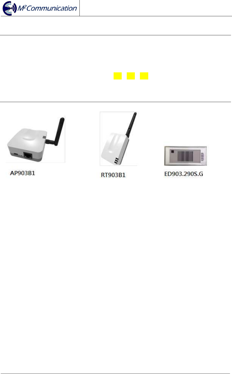
AP903B1
RT903B1
ED903.290S.G

User Guide
AP903B1 / RT903B1 / ED903.290S.G
Copyright © 2015 M
2
Communication Inc Page 2 of 19
CONFIDENTIAL AND
CONFIDENTIAL AND CONFIDENTIAL AND
CONFIDENTIAL AND LIABILITY
LIABILITY LIABILITY
LIABILITY DISCLAIMER
DISCLAIMERDISCLAIMER
DISCLAIMER
Revision History
Revision Release Date Description of Change
0.1 2015/11/24 Initial version

User Guide
AP903B1 / RT903B1 / ED903.290S.G
Copyright © 2015 M
2
Communication Inc Page 3 of 19
Content Summary
1 Scope ................................................................................................................... 4
2 Product Specifications ....................................................................................... 4
2.1
Hardware Specifications ............................................................................................................. 5
2.1.1
AP903B1 ........................................................................................................... 5
2.1.2
RT903B1 ........................................................................................................... 7
2.1.3
ED903.290S.G .................................................................................................. 9
2.2
Software Specifications ............................................................................................................ 11
2.2.1
Network Architecture ....................................................................................... 11
2.2.2
Network Construction ...................................................................................... 12
2.2.3
Data Transmission / Reception ....................................................................... 15
2.2.4
Roaming .......................................................................................................... 16
2.2.5
Integration ....................................................................................................... 17
3 CONTACT INFORMATION ................................................................................ 19
User Guide
AP903B1 / RT903B1 / ED903.290S.G
Copyright © 2015 M
2
Communication Inc Page 4 of 19
1 Scope
This document is to describe hardware / software features of M2Comm product.
AP903B1 stands for M2Comm access point.
RT903B1 stands for M2Comm router.
ED903.290S.G. stands for M2Comm 2.9” B/W/R EPD Tag.
In the following section, the abbreviations AP / RT / ED will be used to describe
product AP903B1 / RT903B1 / ED903.290S.G
2 Product Specifications
AP and RT use MA903A1 RF module to do wireless communication. The MA903A1
has received Federal Communications Commission (FCC) CFR47
Telecommunications, Part 15 Subpart C “Intentional Radiators” 15.247 and modular
approval in accordance with Part 15.212 modular Transmitter approval. MA903A1
FCC ID: 2AFXU-MA903A1. ED FCC ID: 2AFXU-ED903-290S-G.
User Guide
AP903B1 / RT903B1 / ED903.290S.G
Copyright © 2015 M
2
Communication Inc Page 5 of 19
2.1 Hardware Specifications
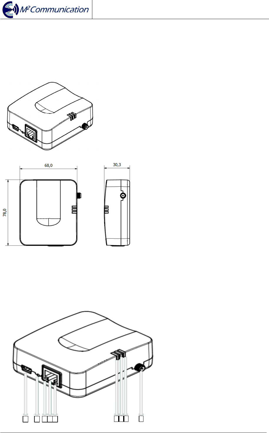
2.1.1 AP903B1
Dimension (+/- 0.3mm)
Outline Structure
1 2 3 4 5 6 7 8 9

User Guide
AP903B1 / RT903B1 / ED903.290S.G
Copyright © 2015 M
2
Communication Inc Page 6 of 19
1. Mini-USB Connector : 5VDC input
2. Reset Button
3. Yellow LED : RJ45 Plug-in
4. Ethernet Input Connector
5. Green LED : Ethernet Data Transceiver
6. Blue LED : Device Power-On
7. Green LED : Reserved
8. Red LED: Power on Self-Test Failure
9. External Antenna SMA Female Connector
Safety Information
- User should avoid electrical shock hazard
- If anything is wrong, do not try to fix it or open the housing by yourself.
Contact a qualified technician or your retailer
- Operating Temperature Range : 0~45℃
- Operating relative humidity: 5~95% (Free of condensed water)
- AC to DC Adapter Voltage input Range : 100V-240V AC, 50/60Hz
Used Certificated Module (MA903A1, FCC ID: 2AFXU-MA903A1 )
Radio Frequency Specification
- Extension 903~927MHz Antenna (The Peak Gain is 2dBi)
Power Input
- Mini-USB Interface
- DC 5 Voltage(+/-0.25V) / 500mA
Reset Button
Index LED
- Green LED (Power On)
- Ethernet Yellow Only (10Mbps Link)
- Ethernet Yellow + Green (100Mbps Link)
- Ethernet Green Flashing (Action Indicator)
Ethernet Interface
- 10/100 BaseT
- Static IP
User Guide
AP903B1 / RT903B1 / ED903.290S.G
Copyright © 2015 M
2
Communication Inc Page 7 of 19
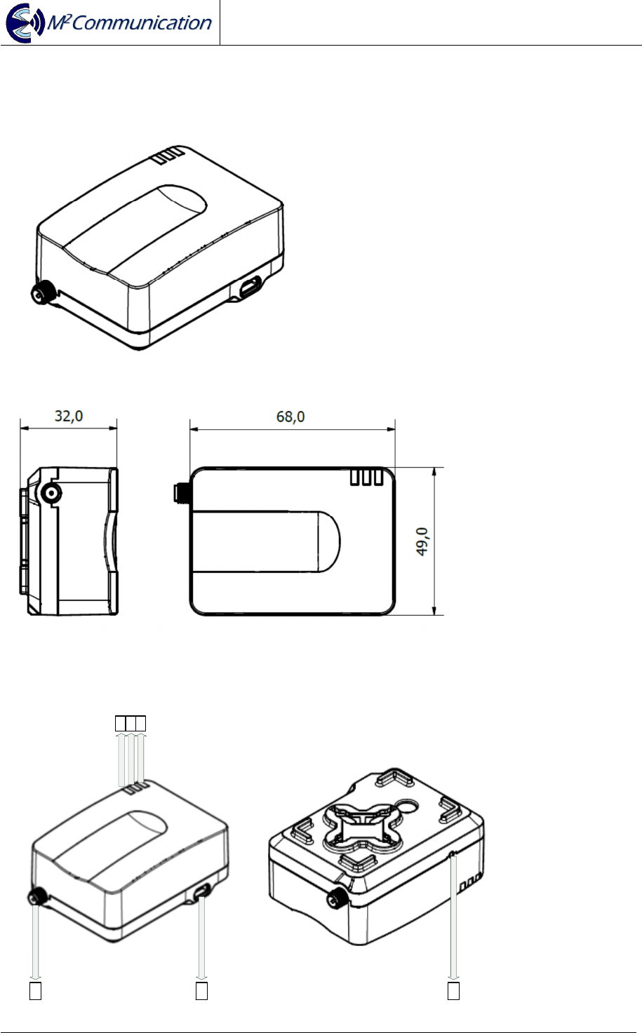
2.1.2 RT903B1
Dimension (+/- 0.3mm)
Outline Structure
1 5 6
2 3 4

User Guide
AP903B1 / RT903B1 / ED903.290S.G
Copyright © 2015 M
2
Communication Inc Page 8 of 19
1. External Antenna SMA Female Connector
2. Blue LED : Attached Platanus Network
3. Red LED : Power on Self-Test Failure
4. Green LED : Power-On LED
5. Mini-USB Connector : 5VDC input
6. Reset Button
Safety Information
- User should avoid electrical shock hazard
- If anything is wrong, do not try to fix it or open the housing by yourself.
Contact a qualified technician or your retailer
- Operating Temperature Range : 0~45℃
- Operating relative humidity: 5~95% (Free of condensed water)
- AC to DC Adapter Voltage input Range : 100V-240V AC, 50/60Hz
Used Certificated Module (MA903A1, FCC ID: 2AFXU-MA903A1)
Radio Frequency Specification
- Extension 903~927MHz Antenna (The Peak Gain is 2dBi)
Power Input
- Mini-USB Interface
- DC 5 Voltage(+/-0.25V) / 500mA
Hidden Button (Reset)
Index LED
- Green LED (Power On)
- Blue LED (Sub-G Connection Up)
- Red LED (Hardware Failure)
User Guide
AP903B1 / RT903B1 / ED903.290S.G
Copyright © 2015 M
2
Communication Inc Page 9 of 19
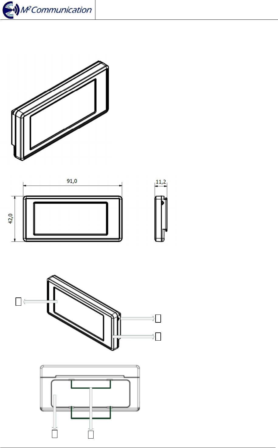
2.1.3 ED903.290S.G
Dimension (+/- 0.25mm)
Outline Structure
1
2
45
3

User Guide
AP903B1 / RT903B1 / ED903.290S.G
Copyright © 2015 M
2
Communication Inc Page 10 of 19
1. 2.9” EPD
2. Hidden Button
3. Anti-Static Case (Surface Impedance 10
~ 10
Ω)
4. Cell Battery Cover
5. Disassembly Hole for the Cell Battery Cover
Safety Information
- User should avoid electrical shock hazard
- If anything is wrong, do not try to fix it or open the housing by yourself.
Contact a qualified technician or your retailer.
- Operating Temperature Range : 0~45℃
- Operating relative humidity: 40~55%
- DO NOT throw the Cell Battery in municipal waste. The Battery should not be
placed in municipal waste.
Certification: FCC ID: 2AFXU-ED903-290S-G
Radio Frequency Specification
- Embedded 903~927MHz PIFA Antenna (Peak Gain 0.3dBi)
Hidden Button
- Wake up (Short Press)
- Deep Sleep (Long Press for 3~5 seconds)
- Show Device Address Barcode from Main Image(Double-click)
- Show Main Image from Device Address Barcode(Double-click)
3pcs of Dischargeable Lithium CR2032 Batteries
ED903.290S.G. EPD Specification
- Support red / black / white color (* note 1)
- Resolution: 296 x 128 pixels
- Power Consumption: 20~21mW
*note1: Please keep EPD panel side up in storage. Inappropriate placement in
storage might turn EPD panel to slight red. EPD will go back to normal once it is
refreshed.
User Guide
AP903B1 / RT903B1 / ED903.290S.G
Copyright © 2015 M
2
Communication Inc Page 11 of 19
2.2 Software Specifications
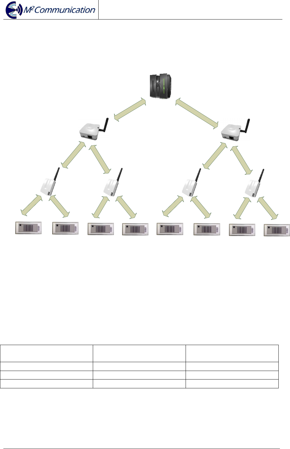
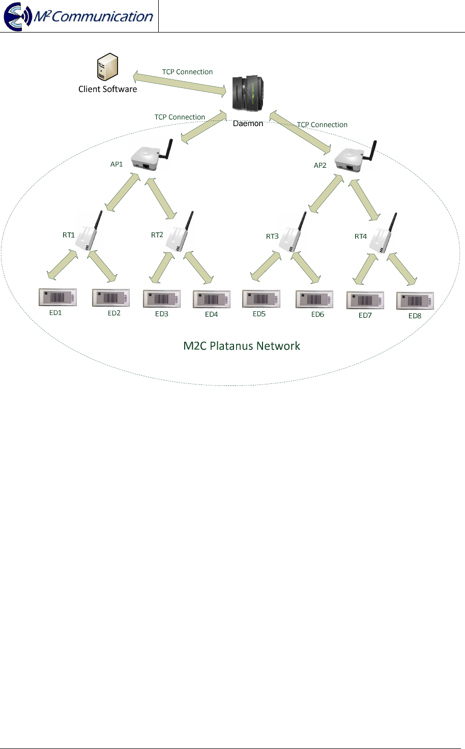
2.2.1 Network Architecture
ED1 ED2 ED3 ED4
RT1
AP1
RT2
ED5 ED6 ED7 ED8
RT3
AP2
RT4
Daemon
M2C Platanus Network
In Platanus network, Daemon is in charge of coordinating multi-APs’ operations.
Under each AP, it can support up to 15 RTs. For every RT can support up to 1000
EDs.
Max # of ED under RT Max # of RT under AP Max # of Device under
Platanus Network
250 60 15000
500 30 15000
1000 15 15000

User Guide
AP903B1 / RT903B1 / ED903.290S.G
Copyright © 2015 M
2
Communication Inc Page 12 of 19
2.2.2 Network Construction
Connection between AP and Router
AP
1. Beacon Frame
2. Join Request 3. Join Response
4. Link report
RT
Step 1: AP broadcasts beacon frame with network parameters
Step 2: RT will send out “Join Request” if AP allows new connection
Step 3: AP confirms the connection is accepted by sending “Join Response”.
Step 4: RT sends a Link report to notify AP that “Join Response” is received and
connection is up now.
User Guide
AP903B1 / RT903B1 / ED903.290S.G
Copyright © 2015 M
2
Communication Inc Page 13 of 19
Connection between Router and ED
RT
1. Beacon Frame
*note2
2. Join Request 3. Join Response
4. Link report
ED
Step 1: RT broadcasts beacon frame with network parameters
Step 2: ED will send out “Join Request” if RT allows new connection
Step 3: RT confirms the connection is accepted by sending “Join Response”.
Step 4: ED sends a Link report to notify RT that “Join Response” is received and
connection is up now.
* note 2: RT will only send out beacon frame when it connects to AP

User Guide
AP903B1 / RT903B1 / ED903.290S.G
Copyright © 2015 M
2
Communication Inc Page 14 of 19
Connection between Daemon and AP
Step 1: Specify AP’s IP address from Daemon Configuration file.
Step 2: Execute Daemon
Step 3: TCP connection will be constructed and information starts to exchange
between AP and Daemon.
* note3: For more information, please refer to M2C “Daemon User Guide”
User Guide
AP903B1 / RT903B1 / ED903.290S.G
Copyright © 2015 M
2
Communication Inc Page 15 of 19
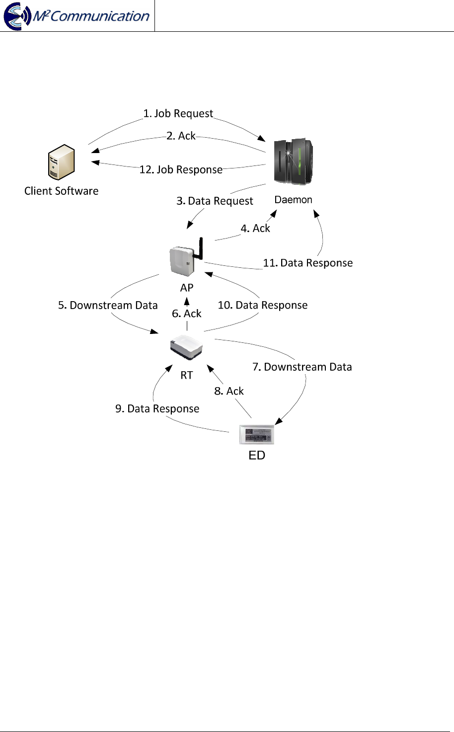
2.2.3 Data Transmission / Reception
Data (or Request) is initiated from customer software that is integrated with M2C
Daemon by TCP connection (* note4).
To utilize limited Radio Frequency resources, M2C designs a reliable data
transmission model to increase the success rate of both data transmission /
reception. Each transaction between any of two sides is secured by Data-
Acknowledgment mechanism.
* note 4: For more information of Daemon integration, please refer to M2C
“Daemon User Guide”
User Guide
AP903B1 / RT903B1 / ED903.290S.G
Copyright © 2015 M
2
Communication Inc Page 16 of 19
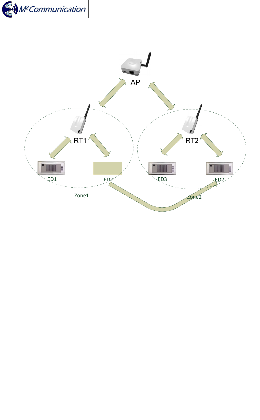
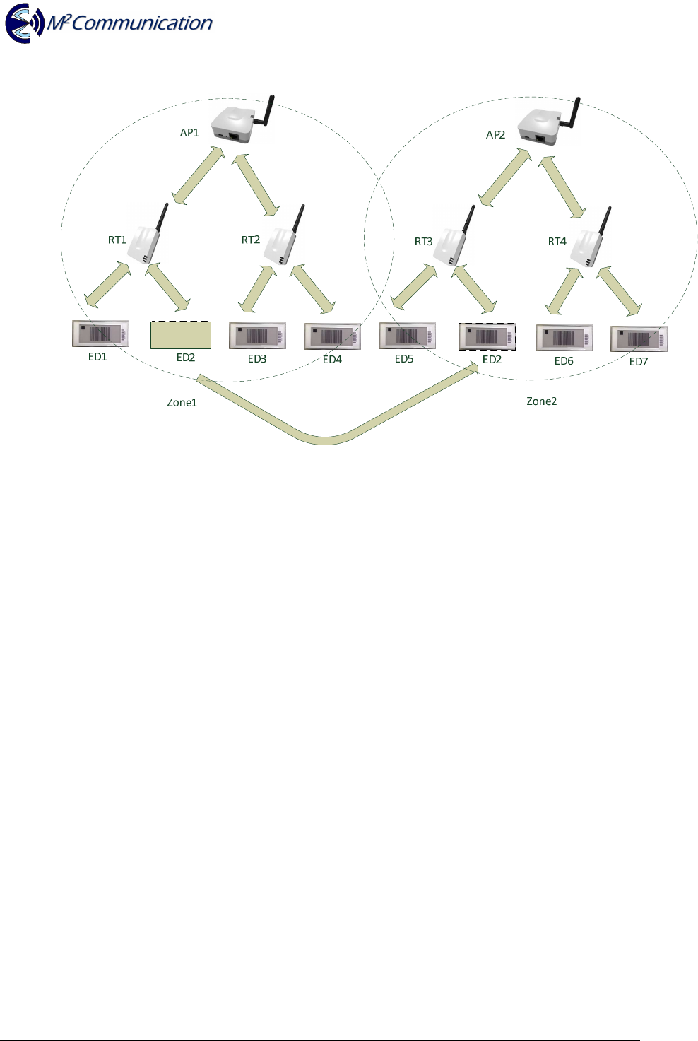
2.2.4 Roaming
Inter-RT Roaming
When ED2 moves from Zone1 to Zone2, ED2 will camp on RT2. The inter-RT
roaming process will be completed in 5 seconds.
User Guide
AP903B1 / RT903B1 / ED903.290S.G
Copyright © 2015 M
2
Communication Inc Page 17 of 19
Inter-AP Roaming
When ED2 moves from Zone1 to Zone2, ED2 will camp on RT3. The inter-AP
roaming process will be completed in 8 seconds.
2.2.5 Integration
As a service or job dispatch portal, M2C Daemon software can be installed in PC
with average computing power & resource (* note5). M2C Daemon equips with
TCP/IP socket that can provide a reliable connection between client (customer)
software. Also via M2C Daemon, client software can manipulate M2C Platanus
network. For more details regarding to integration with M2C Daemon, please refer to
“M2C Daemon User Guide”.
* note5: Minimal requirements: intel i5 CPU / 1TB HDD / 8GB DDR3 RAM
User Guide
AP903B1 / RT903B1 / ED903.290S.G
Copyright © 2015 M
2
Communication Inc Page 18 of 19

User Guide
AP903B1 / RT903B1 / ED903.290S.G
Copyright © 2015 M
2
Communication Inc Page 19 of 19
3 CONTACT INFORMATION
M
2
Communication, Inc. (M2Comm)
4F-3, No.32, Gaotie 2nd Rd.,
Zhubei City, Hsinchu County, Taiwan
Tel: +886-3-657-8939
Fax: +886-3-657-6909
Email: support@m2comm.com.tw
This document contains confidential information and is subject to the terms and conditions set forth in the Non-
Disclosure Agreement between the Recipient Entity and M
2
Communication, Inc. (M2C) The information in this
document is believed to be accurate in all respects at the time of publication but is subject to change without
notice. M
2
Communication, Inc. assumes no responsibility for errors and omissions, and disclaims responsibility
for any consequences resulting from the use of information included herein. Additionally, M
2
Communication,
Inc. assumes no responsibility for the functioning of un-described features or parameters. M
2
Communication,
Inc. reserves the right to make changes without further notice. M
2
Communication, Inc. makes no warranty,
representation or guarantee regarding the suitability of its products for any particular purpose, nor does
M
2
Communication, Inc. assume any liability arising out of the application or use of any product or circuit, and
specifically disclaims any and all liability, including without limitation consequential or incidental damages.
M
2
Communication, Inc. products are not designed, intended, or authorized for use in applications intended to
support or sustain life, or for any other application in which the failure of the M
2
Communication, Inc. product
could create a situation where personal injury or death may occur. Should Buyer purchase or use
M
2
Communication, Inc. products for any such unintended or unauthorized application, Buyer shall indemnify
and hold M
2
Communication, Inc. harmless against all claims and damages.