M2Micro 6M2MCD M2micro Center Control Unit User Manual linda
M2Micro(Changshu)Co., Ltd. M2micro Center Control Unit linda
M2Micro >
Contents
- 1. User Manual
- 2. User manual
User manual

MCC6000-CD01
Installation Guide

Statement
This manual is property of M2Micro (Changshu) Co., Ltd. with all rights reserved.
Any imitation, copying, transcript, or translation without the prior written permission
of the Company is prohibited. Any dissemination of the product in any form or by any
means (electronic, mechanical, photocopying, recording or otherwise) or any use for
any commercial, or profit purpose is also forbidden.
is a registered trademark solely for M2Micro (Changshu) Co., Ltd. All other
trademarks or registered trademarks mentioned herein are owned by their respective
owners.
Product specifications and information referred in this manual are for reference only;
we reserve the right to update relevant content without further notice. For more
information, please visit our website at any time:
http://www.m2micro.com
Unless otherwise specified, this manual is only be used as guidance. While every
attempt has been made to ensure all information in this manual is accurate, the
Company should not be held liable for any error or omission in this document.

FCC STATEMENT
This equipment has been tested and found to comply with the limits for a Class B digital
device, pursuant to part 15 of the FCC Rules. These limits are designed to provide
reasonable protection against harmful interference in a residential installation. This
equipment generates, uses and can radiate radio frequency energy and, if not installed
and used in accordance with the instructions, may cause harmful interference to radio
communications. However, there is no guarantee that interference will not occur in a
particular installation. If this equipment does cause harmful interference to radio or
television reception, which can be determined by turning the equipment off and on,
the user is encouraged to try to correct the interference by one or more of the
following measures:
Reorient or relocate the receiving antenna.
Increase the separation between the equipment and receiver.
Connect the equipment into an outlet on a circuit different from that to which
the receiver is connected.
Consult the dealer or an experienced radio/TV technician for help.
This device complies with part 15 of the FCC Rules. Operation is subject to the following
two conditions:
1) This device may not cause harmful interference.
2) this device must accept any interference received, including interference that may

cause undesired operation.
⚠Caution: Any changes or modifications to this device not explicitly approved by
manufacturer could void your authority to operate this equipment.
This equipment complies with FCC RF radiation exposure limits set forth for an
uncontrolled environment. This device and its antenna must not be located or
operating in conjunction with any other antenna or transmitter.
“To comply with FCC RF exposure compliance requirements, this grant is applicable to
only mobile configurations. The antennas used for this transmitter must be installed to
provide a separation distance of at least 20 cm from all persons and must not be
co-located or operating in conjunction with any other antenna or transmitter.”
Preface
Manual instruction
This Installation Guide describes the hardware features, installation methods and
points for attention during installation.
To avoid possible equipment damage or personal injury before and during the
installation process, please read this manual carefully.
Overview of this guide
Chapter Instruction
1-Introduction Outlined the basic functionality and product features.
2-Installation Describes product installation methods and attentions.
A-Data sheet Lists the hardware specifications.
Version
Date Version Update description
2011-11-23 R20111123-V1.00 Manual initial release.
2013-2-22 R20130222-V1.01 Increase FCC certification.

Conventions
Unless otherwise specified, the terms of ”systems”, “equipment”, “products” in the
following parts of this manual refer to the MMR6000 meter reading system.
Two signs are used herein to draw the users’ attention during the operation, with
meanings as follows:
⚠Caution
This icon is used to list advertent items during
operation and to remind the users of undesirable
consequences due to inaccurate operation, such as
potential damage to the equipment or otherwise.
Tips This icon is to give supplementary explanation for
the operation details described.

I
Contents
1 Introduction ................................................................................................ 1
1.1 Product Overview ......................................................................................... 1
1.2 Features ......................................................................................................... 1
1.3 Demonstration of the type ........................................................................... 2
1.4 Network topology .......................................................................................... 3
2 Installation .................................................................................................. 5
2.1 Packing list .................................................................................................... 4
2.2 Internal structure ........................................................................................... 4
2.3 Appearance ................................................................................................... 5
2.3.1 Dimension .............................................................................................. 5
2.3.2 LEDs introduction ................................................................................... 5
2.4 Installation....................................................................................................... 6
2.4.1 Instruction .............................................................................................. 6
2.4.2 Connection ............................................................................................. 7

1
1 Introduction
1.1 Product Overview
Automatic Meter Reading (AMR), also called remote meter reading system, is a new
meter reading way to finish meter reading without people on site. Via
communication technology, it can be automatically transferred to the data in
Watt-hour meter the accounting and management center for efficient handling.
Also, it can be provided real-time measurement information to help the users to
optimize their energy supply solutions.
Aiming at AMR application, M2Micro launches its MMR6000 AMR system, which
supports ad hoc network and data collection for various types of meters. It is mainly
made up of MRU6000 terminal units and MCC6000 control units and OMS meter
management system.
The main function of MCC6000 is remote data forwarding. In downlink direction, it
receives data collected from meters by the wireless terminal units, and in uplink
direction, it sends data to OMS meter management system by wired connection or
GSM wireless network.
1.2 Features
Modular design, existing meters can be upgraded by attaching wireless AMR
modules.
MCC6000 Installation Guide
2
Support hybrid meter reading, can collect data of water meter, gas meter,
etc.
Based on M2Micro developed chips, MAC and PHY layer can work together
perfectly.
Support 433.92MHz frequency band, with good transportation distance and
penetration.
Support Ad-hoc network, can be deployed to complicate environment.
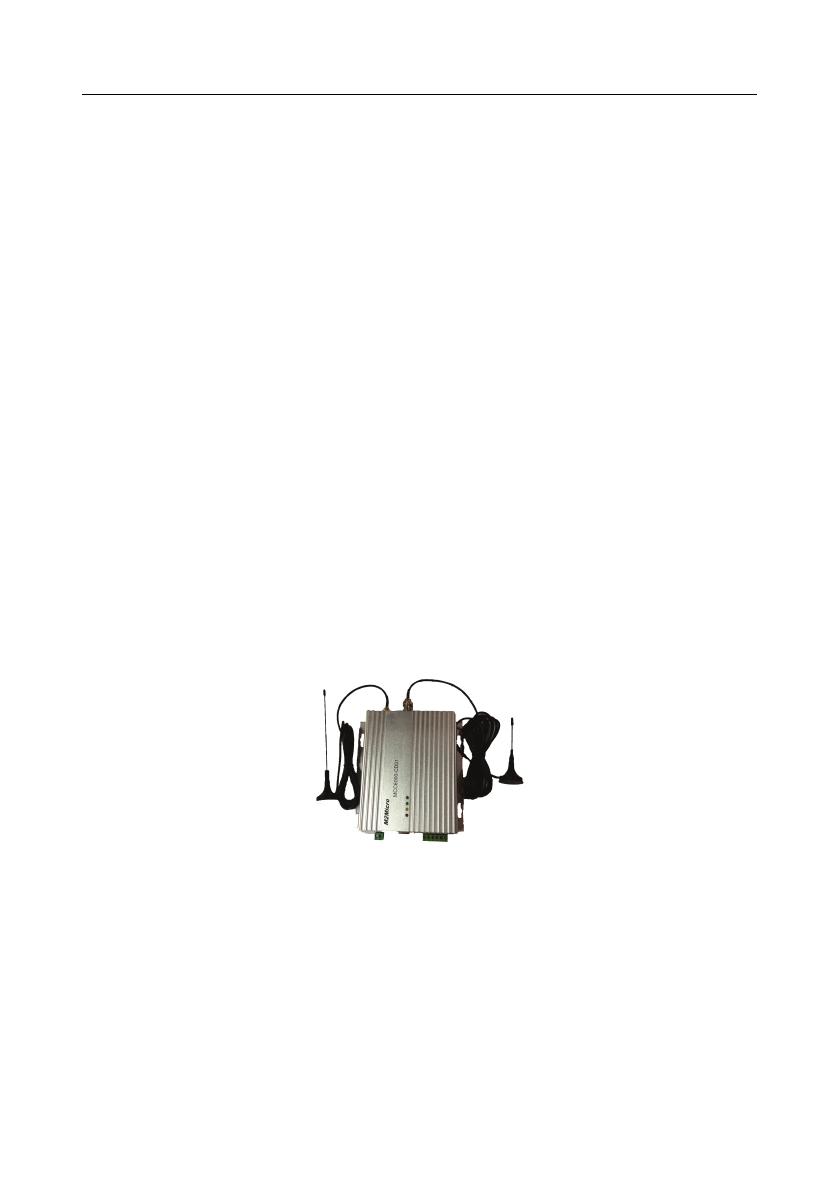
1.3 Demonstration of the type
Based on transfer mode of uplink data, MCC6000 series can be classified into 2
models, i.e.
Figure 1 MCC6000-CD01,
MCC6000-DD01
1Introduction
3
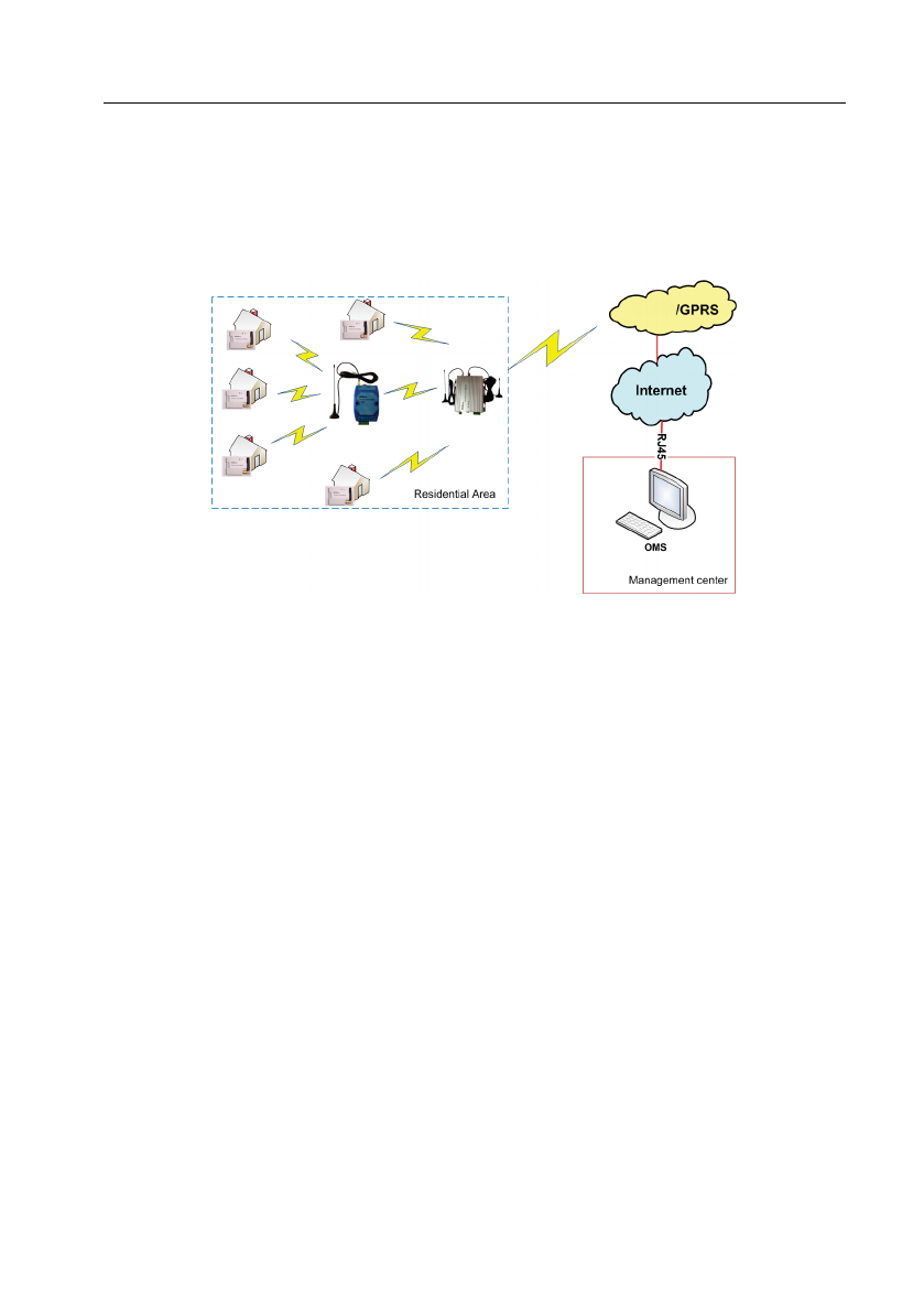
1.4 Network topology
The following figure shows the network topology for MMR6000.
Figure 2 Network topology
GSM
4
2 Installation
2.1 Packing list
Make sure that the package contains the following items.
Serial no. Item Quantity
A MCC6000 1
B
antenna(Only for CD01) 1
C This Installation Guide 1
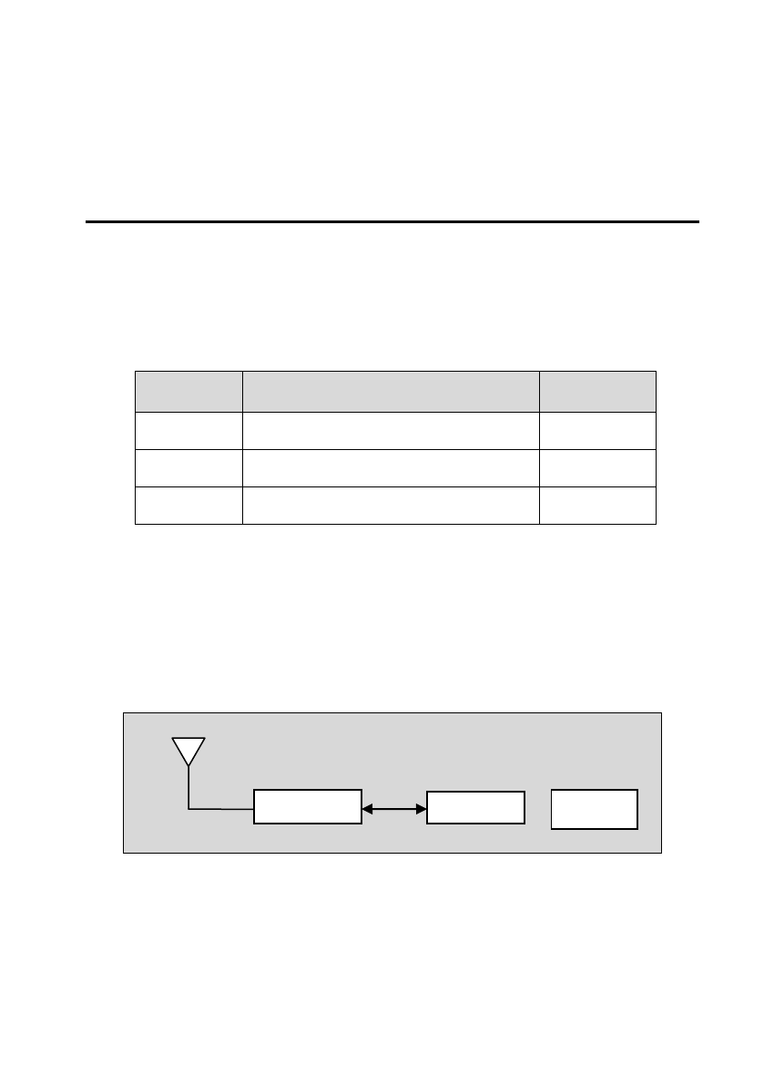
2.2 Internal structure
The internal structure of MCC6000 is shown in Figure 3.
Figure 3 The internal structure of MCC
Antenna: Bi-directional wireless data communication.
M2M6001: Meter data transfer.
MCC
M2M6001 DC power
Antenna MCU
GSM /GPRS
MCC6000 Installation Guide
5
MCU: Wireless network management, and data transfer-control.
DC power: Provide stable current to the whole control unit.
2.3 Appearance
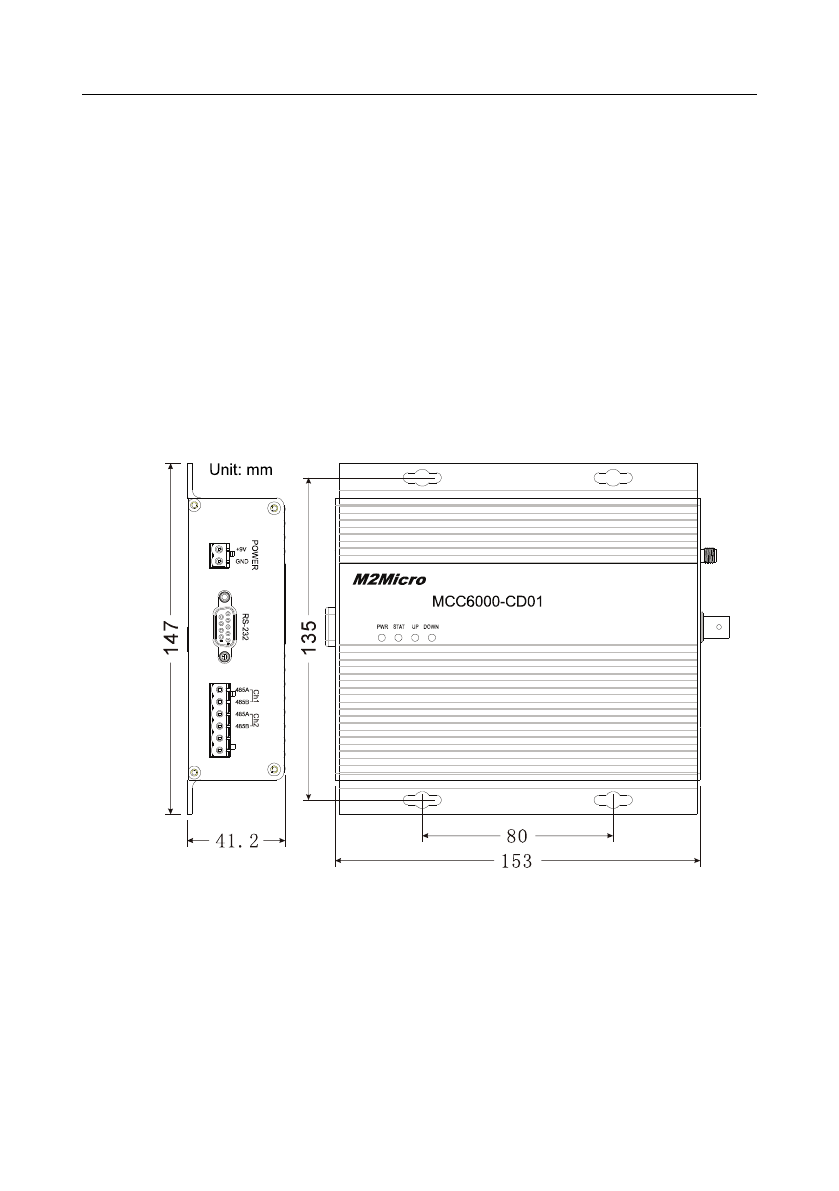
2.3.1 Dimension
Before installation, please select the place for installation according to the product
size.
Figure 4 The dimension of MCC6000
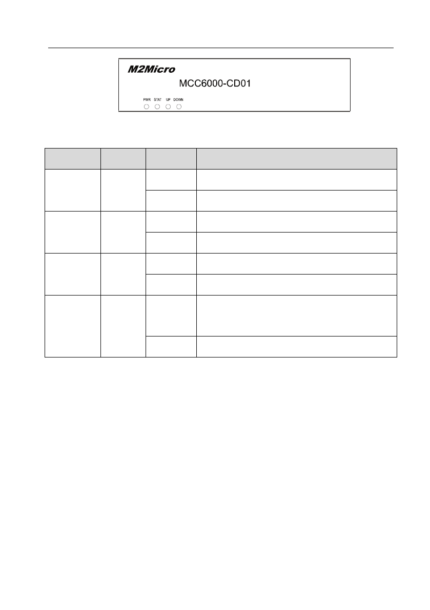
2.3.2 LEDs introduction
LED of MCC6000 is shown in the following figure.
2Installation
6
Figure 5 LED of MCC6000
LED Color Status Comments
Power Red On The device is powered on.
Off The device is powered off.
Status Yellow On The network is open.
Off The network is not open.
Uplink Green Flashing Data is being communicated with OMS.
Off Login Server already. But no data transmission.
Downlink Green Flashing Data is being communicated between MCC and
MRU.
Off No data transmission between MCC and MRU.
2.4 Installation
2.4.1 Instruction
MCC6000 is should be installed inside a box which is solid, waterproof and difficult
to shake in. Through the back of MCC500, left four mounting holes, four M4 × 12
self-tapping screws can be used to fix mounted MCC6000 on the wall.
MCC6000 Installation Guide
7
Figure 6
2.4.2 Connection
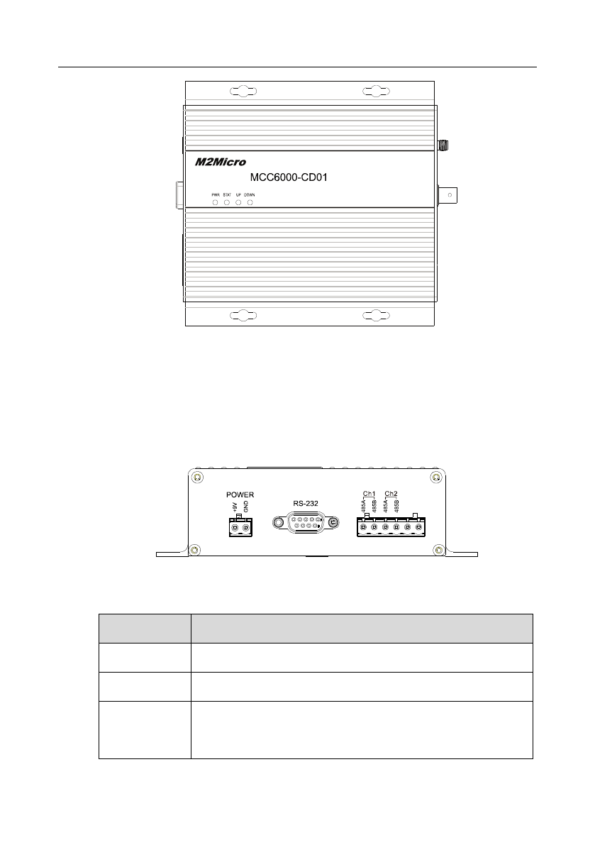
The left panel of MCC6000-CD01 is shown in the following figure.
Figure 7 Left panel of MCC6000-CD01
Port Comments
POWER Power input. Input voltage is 9V DC.
RS-232 RS-232 connector.
Ch1/Ch2 RS485 connector.
Ch1 is used for the connection connected with electrical
2Installation
8
energy data acquisition;
Ch2 is reserved for the connection, which is connected with
water meter or gas meter and other types of meters.
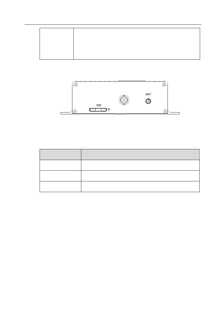
The right panel of MCC6000-CD01 is shown in the following figure.
Figure 8 Right panel of MCC6000-CD01
Port Comments
SIM SIM card slot.
.
ANT Connector to the wireless antenna.
GSM /GPRS Connector to the GSM /GPRS communication antenna
GSM/GPRS

9
A Appendix - Data Sheet
MCC6000-CD01
Parameter Value
Input Voltage AC220V±20% 50Hz
Operating Temperature -40~70°C
Operating Humidity <95%
Maximum Number of
Mounted MRU
200
Mean Time Between Failures MTBF > 2x10⁴ hours
Electrostatic Discharge 8kV
Transient rapid pulse group 1kV
Impulse Withstand Voltage 4kV
Communication Port
Uplink
Downlink: Wireless data transmission
: GSM /GPRS or RS232

10
MCC6000-DD01
Parameter Value
Input Voltage AC220V±20% 50Hz
Operating Temperature -40~85°C
Operating Humidity <95%
Maximum Number of
Mounted MRU
200
Mean Time Between Failures MTBF > 2x10⁴ hours
Electrostatic Discharge 8kV
Transient rapid pulse group 1kV
Impulse Withstand Voltage 4kV
Communication Port
Uplink: RS232
Downlink: Wireless data transmission